- Table of Contents
- Related Documents
-
| Title | Size | Download |
|---|---|---|
| 01-IPv4 over IPv4 tunneling configuration | 154.95 KB |
About IPv4 over IPv4 tunneling
Restrictions and guidelines: IPv4 over IPv4 tunnel configuration
Configuring an IPv4 over IPv4 tunnel
Testing the reachability of a path
Configuring a source-destination address pair for IPv4-in-IPv4 packet decapsulation
Constructing multi-layer encapsulated IPv4-in-IPv4 packets on a host
Testing the reachability of a path
Verifying and maintaining IPv4 over IPv4 tunneling
Displaying IPv4 over IPv4 tunnel interface information
Clearing IPv4 over IPv4 tunnel interface statistics
IPv4 over IPv4 tunneling
About IPv4 over IPv4 tunneling
IPv4 over IPv4 tunneling (RFC 1853) enables isolated IPv4 networks to communicate. For example, an IPv4 over IPv4 tunnel can connect isolated private IPv4 networks over a public IPv4 network.
Figure 1 IPv4 over IPv4 tunnel
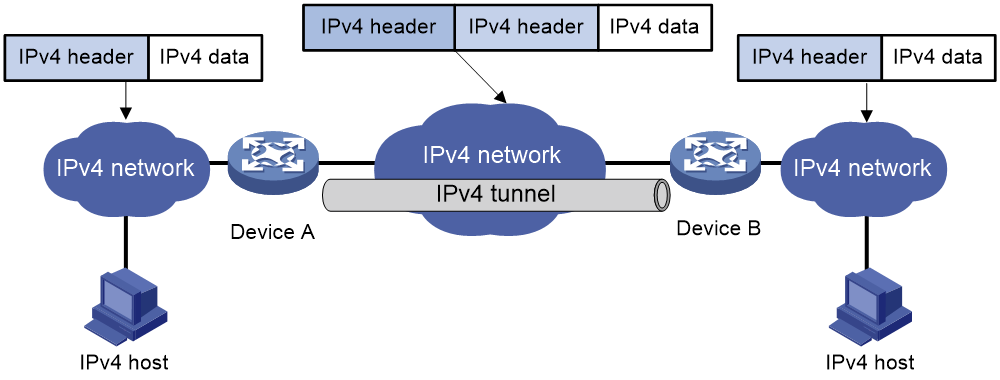
Figure 1 shows the encapsulation and de-encapsulation processes.
· Encapsulation:
a. Device A receives an IP packet from an IPv4 host and submits it to the IP protocol stack.
b. The IPv4 protocol stack determines how to forward the packet according to the destination address in the IP header. If the packet is destined for the IPv4 host connected to Device B, Device A delivers the packet to the tunnel interface.
c. The tunnel interface adds a new IPv4 header to the IPv4 packet and submits it to the IP protocol stack.
In the new header, the source IP address specifies the tunnel source, and the destination IP address specifies the tunnel destination.
d. The IP protocol stack uses the destination IP address of the new IP header to look up the routing table, and then sends the packet out.
· De-encapsulation:
a. After receiving the packet, Device B delivers it to the IP protocol stack.
b. If the protocol number is 4 (indicating an IPv4 packet is encapsulated within the packet), the IP protocol stack delivers the packet to the tunnel module for de-encapsulation.
c. The tunnel module de-encapsulates the IP packet and sends it back to the IP protocol stack.
d. The protocol stack forwards the de-encapsulated packet.
Restrictions and guidelines: IPv4 over IPv4 tunnel configuration
Follow these guidelines when you configure an IPv4 over IPv4 tunnel:
· The tunnel destination address specified on the local device must be identical with the tunnel source address specified on the tunnel peer device.
· Do not specify the same source and destination addresses for local tunnel interfaces in the same tunnel mode.
· The IPv4 address of the local tunnel interface cannot be on the same subnet as the destination address configured on the tunnel interface.
· To ensure correct packet forwarding, identify whether the destination IPv4 network and the IPv4 address of the local tunnel interface are on the same subnet. If they are not, configure a route reaching the destination IPv4 network through the tunnel interface. You can configure the route by using one of the following methods:
¡ Configure a static route, and specify the local tunnel interface as the egress interface or specify the IPv4 address of the peer tunnel interface as the next hop.
¡ Enable a dynamic routing protocol on both the local and remote tunnel interfaces.
For more information about route configuration, see Layer 3—IP Routing Configuration Guide.
· The destination address of the route passing the tunnel interface cannot be on the same subnet as the destination address configured on the tunnel interface.
· IPv4 over IPv4 tunnel configuration commands include the following common tunnel interface commands:
¡ interface tunnel.
¡ source.
¡ destination.
¡ tunnel dfbit enable.
For more information about these and more tunnel interface commands, see Interface Command Reference.
· When the length of a packet passing through a tunnel exceeds the MTU, the packet will be sent to the CPU for forwarding. When the length of a packet passing through a tunnel is less than the MTU, the packet will be normally forwarded through hardware.
Configuring an IPv4 over IPv4 tunnel
1. Enter system view.
system-view
2. Enter IPv4 over IPv4 tunnel interface view.
interface tunnel number [ mode ipv4-ipv4 ]
3. Configure an IPv4 address for the tunnel interface.
ip address ip-address { mask | mask-length } [ sub ]
4. Configure a source address or source interface for the tunnel interface.
source { ipv4-address | interface-type interface-number }
By default, no source address or source interface is configured for the tunnel interface.
If you specify a source address, it is used as the source IP address of tunneled packets.
If you specify a source interface, the primary IP address of this interface is used as the source IP address of tunneled packets.
5. Configure a destination address for the tunnel interface.
destination ipv4-address
By default, no destination address is configured for the tunnel interface.
The tunnel destination address must be the IP address of the receiving interface on the tunnel peer. It is used as the destination IP address of tunneled packets.
6. (Optional.) Set the DF bit for tunneled packets.
tunnel dfbit enable
By default, the DF bit is not set for tunneled packets.
Testing the reachability of a path
Configuring a source-destination address pair for IPv4-in-IPv4 packet decapsulation
About this task
In some scenarios, a host needs to construct multi-layer encapsulated IPv4-in-IPv4 packets to detect whether a transmission path is reachable. Use this feature on each node along the transmission path to configure a source-destination address pair used to decapsulate the IPv4-in-IPv4 packets.
A source-destination address pair contains a destination address and multiple source IP addresses. The destination address is optional. If you do not specify a destination address, the default setting is 0.0.0.0. You can use one of the following methods to specify multiple source IP addresses:
· Use the source ip-address option to specify a local IP address that is reachable as the source IP address.
· Use the source interface-type interface-number option to specify a source interface. The primary IP address of the interface is used as the source IP address.
· Use the source direct keyword to specify a group of source IP addresses. With this keyword, the system traverses all local Layer 3 interfaces, VLAN interfaces, and loopback interfaces in up state. The source IP addresses used for packet decapsulation are the primary IP addresses of the first 1000 interfaces (except subinterfaces, interfaces in VPN instances, and inloopback interfaces).
Restrictions and guidelines
Configure a source-destination address pair on each node along the path to be detected. On the end node, you can specify a source IP address, a source interface, or a group of source IP addresses. On the other nodes, you must use the source direct keyword to specify a group of source IP addresses.
Procedure
1. Enter system view.
system-view
2. Configure a source-destination address pair for IPv4-in-IPv4 packet decapsulation.
tunnel ip-in-ip decapsulate-any [ destination ip-address ] source { ip-address | interface-type interface-number | direct }
By default, no source-destination address pair is configured for IPv4-in-IPv4 packet decapsulation.
This command allows the device to decapsulate only an IPv4 address at the outermost layer and IPv4 and IPv6 addresses are at inner layers for IPv4-in-IPv4 packet decapsulation.
Constructing multi-layer encapsulated IPv4-in-IPv4 packets on a host
Set the destination address of a packet as the IP address of the host, and then encapsulate IP headers layer by layer to the packet.
The encapsulation order of IP headers in the IPv4-in-IPv4 packet must be opposite to the order of nodes along the path that the packet traverses. The number of encapsulated IP headers is the number of link node devices × 2 - 1.
In the IPv4-in-IPv4 packet, the source and destination addresses in an IP header must be consistent with the source-destination address pair on the node that decapsulates that IP header.
· The source address in the IP header must be the same as the destination address in the source-destination address pair.
· The destination address in the IP header must be one of the source IP addresses in the source-destination address pair.
Testing the reachability of a path
When a multi-layer encapsulated IPv4-in-IPv4 packet passes through a node, the node matches the outmost source and destination addresses of the packet with the local source-destination address pair.
· If the addresses match, the node decapsulates the outmost IP header from the packet.
· If the addresses do not match, the node does not decapsulate the outmost IP header from the packet.
After the node decapsulates the IP header, it forwards the packet to the next node according to the forwarding table. The subsequent nodes along the path successively perform the same matching and decapsulation operations as this node until the end node completes the decapsulation. Because the destination address of the original packet is the host's IP address, the end node forwards the packet back to the host.
· If the packet can return to the host, the path is reachable.
· If the packet cannot return to the host, the path is not reachable.
For example, test the reachability of a path that has two nodes. The test order is Host—>A—>B.
Figure 2 IPv4-in-IPv4 packet decapsulation workflow
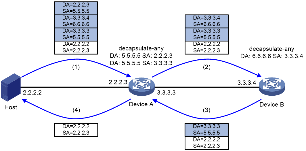
The workflow is as follows:
1. The host constructs a multi-layer decapsulated IPv4-in-IPv4 packet and sends it to Device A.
2. After receiving the packet, Device A finds that the outmost IP header of the packet matches the local source-destination address pair for IPv4-in-IPv4 packet decapsulation. Then, Device A decapsulates the outmost IP header from the packet and forwards the packet to Device B according to the forwarding table.
3. After receiving the packet, Device B finds that the outmost IP header of the packet matches the local source-destination address pair for IPv4-in-IPv4 packet decapsulation. Then, Device B decapsulates the outmost IP header from the packet and forwards the packet to the next node (Device A) according to the forwarding table.
4. Device A repeats the matching and decapsulation operations the same as Device B to decapsulate the last layer of IP header from the packet. Then, Device A forwards the packet to the host according to the forwarding table.
5. The host receives the packet or not. If the host receives the packet, the path is reachable. If the host does not receive the packet, the path is not reachable.
Verifying and maintaining IPv4 over IPv4 tunneling
Displaying IPv4 over IPv4 tunnel interface information
This section only lists commands available for displaying IPv4 over IPv4 tunnel interface information. For more information about the commands, see tunnel interface commands in Interface Command Reference.
Perform display tasks in any view.
· Display IPv4 over IPv4 tunnel interface information.
display tunnel-interface [ number ]
· Display information about IPv4 over IPv4 tunnel interfaces.
display interface [ tunnel [ number ] ] [ brief [ description | down ] ]
Clearing IPv4 over IPv4 tunnel interface statistics
To clear IPv4 over IPv4 tunnel interface statistics, execute the following command in user view:
reset counters interface [ tunnel [ number ] ]
For more information about this command, see common interface commands in Interface Command Reference.
IPv4 over IPv4 tunnel configuration examples
Example: Configuring an IPv4 over IPv4 tunnel
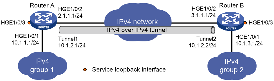
Network configuration
As shown in Figure 3, the two subnets IPv4 group 1 and IPv4 group 2 use private IPv4 addresses. Configure an IPv4 over IPv4 tunnel between Router A and Router B to make the two subnets reachable to each other.
Prerequisites
Make sure Router A and Router B can reach each other through IPv4.
Procedure
1. Configure Router A:
# Specify an IPv4 address for HundredGigE 1/0/1.
<RouterA> system-view
[RouterA] interface hundredgige 1/0/1
[RouterA-HundredGigE1/0/1] ip address 10.1.1.1 255.255.255.0
[RouterA-HundredGigE1/0/1] quit
# Specify an IPv4 address for HundredGigE 1/0/2, which is the physical interface of the tunnel.
[RouterA] interface hundredgige 1/0/2
[RouterA-HundredGigE1/0/2] ip address 2.1.1.1 255.255.255.0
[RouterA-HundredGigE1/0/2] quit
# Create IPv4 over IPv4 tunnel interface Tunnel 1.
[RouterA] interface tunnel 1 mode ipv4-ipv4
# Specify an IPv4 address for the tunnel interface.
[RouterA-Tunnel1] ip address 10.1.2.1 255.255.255.0
# Specify the IP address of HundredGigE 1/0/2 as the source address for the tunnel interface.
[RouterA-Tunnel1] source 2.1.1.1
# Specify the IP address of HundredGigE 1/0/2 on Router B as the destination address for the tunnel interface.
[RouterA-Tunnel1] destination 3.1.1.1
[RouterA-Tunnel1] quit
# Configure a static route destined for IPv4 group 2 through the tunnel interface.
[RouterA] ip route-static 10.1.3.0 255.255.255.0 tunnel 1
2. Configure Router B:
# Specify an IPv4 address for HundredGigE 1/0/1.
<RouterB> system-view
[RouterB] interface hundredgige 1/0/1
[RouterB-HundredGigE1/0/1] ip address 10.1.3.1 255.255.255.0
[RouterB-HundredGigE1/0/1] quit
# Specify an IPv4 address for HundredGigE 1/0/2, which is the physical interface of the tunnel.
[RouterB] interface hundredgige 1/0/2
[RouterB-HundredGigE1/0/2] ip address 3.1.1.1 255.255.255.0
[RouterB-HundredGigE1/0/2] quit
# Create IPv4 over IPv4 tunnel interface Tunnel 2.
[RouterB] interface tunnel 2 mode ipv4-ipv4
# Specify an IPv4 address for the tunnel interface.
[RouterB-Tunnel2] ip address 10.1.2.2 255.255.255.0
# Specify the IP address of HundredGigE 1/0/2 as the source address for the tunnel interface.
[RouterB-Tunnel2] source 3.1.1.1
# Specify the IP address of HundredGigE 1/0/2 on Router A as a destination address for the tunnel interface.
[RouterB-Tunnel2] destination 2.1.1.1
[RouterB-Tunnel2] quit
# Configure a static route destined for IPv4 group 1 through the tunnel interface.
[RouterB] ip route-static 10.1.1.0 255.255.255.0 tunnel 2
Verifying the configuration
# Use the display interface tunnel command to display the status of the tunnel interfaces on Router A and Router B. Verify that the tunnel interfaces are up. (Details not shown.)
# Verify that Router A and Router B can ping the IPv4 address of the peer interface HundredGigE 1/0/1. This example uses Router A.
[RouterA] ping -a 10.1.1.1 10.1.3.1
Ping 10.1.3.1 (10.1.3.1) from 10.1.1.1: 56 data bytes, press CTRL_C to break
56 bytes from 10.1.3.1: icmp_seq=0 ttl=255 time=2.000 ms
56 bytes from 10.1.3.1: icmp_seq=1 ttl=255 time=1.000 ms
56 bytes from 10.1.3.1: icmp_seq=2 ttl=255 time=0.000 ms
56 bytes from 10.1.3.1: icmp_seq=3 ttl=255 time=1.000 ms
56 bytes from 10.1.3.1: icmp_seq=4 ttl=255 time=1.000 ms
--- Ping statistics for 10.1.3.1 ---
5 packet(s) transmitted, 5 packet(s) received, 0.0% packet loss
round-trip min/avg/max/std-dev = 0.000/1.000/2.000/0.632 ms
