- Table of Contents
- Related Documents
-
| Title | Size | Download |
|---|---|---|
| 01-Text | 1.46 MB |
General safety recommendations
Examining the installation site
Cement ceiling/Ceiling/Workbench
General cable layout requirements
Mounting the device to a cement ceiling
Installing the device to ceiling
Checking the ceiling for installation
8 Device initial power on and startup
Local login through the CONSOLE port
Configuring terminal parameters
Logging in to the device through the CONSOLE port
Logging in to the device through Telnet
Logging in to the device through wired connection
Logging in to the device wirelessly
Logging in to the device through the web interface
Logging in to the web interface through a wired connection
Logging in to the web interface wirelessly
Logging out of the web interface
9 Managing the device through Cloudnet
Downloading and installing the Cloudnet app
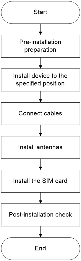
1 Installation flowchart
The device installation process is as shown in Figure1-1.
Figure1-1 Installation flowchart
2 Preparing for installation
Safety recommendations
To avoid any equipment damage or bodily injury caused by improper use, read the following safety recommendations before installation. Note that the recommendations do not cover every possible hazardous condition. When performing operations, you should also comply with the safety regulations of the location.
Do not attempt to carry out maintenance or debugging inside the equipment on your own, in order to avoid injuries caused by unforeseen or other abnormal factors.
General safety recommendations
· Only qualified professionals or trained personnel can install, operate, or maintain the device.
· Do not place the device on an unstable case or desk. The device might be severely damaged in case of a fall.
· During the operation of electrical equipment, the surface of the device might become hot. Install the equipment in a restricted access area. Only maintenance personnel or trained individuals should access equipment in restricted areas, to prevent others from touching it and to avoid burns.
· Keep the chassis clean and dust-free.
· Do not place the device near water or in a damp environment. Prevent water or moisture from entering the device chassis.
· It is strictly forbidden to store flammable and explosive items in and around the area where the equipment is located.
· Handle the devices according to the sizes of and packaging symbols on the packages.
Electricity safety
· Carefully examine your work area for possible hazards, such as ungrounded power extension cables, missing safety grounds, or moist floors.
· Locate the emergency power-off switch in the room before installation, operation, and maintenance so you can shut off the power immediately if an accident occurs. Remove the power cord if necessary.
· Make sure the operating voltage is in the required range.
· Make sure the device is correctly grounded before powering on the device if grounding is required.
Moving safety
· Lift and put down the chassis slowly and never move it suddenly.
· After you move the device from a location below 0°C (32°F) to the equipment room, follow these guidelines to prevent condensation:
¡ Wait a minimum of 30 minutes before unpacking the device.
¡ Wait a minimum of 2 hours before powering on the device.
· Remove all external cables before moving the device.
· If the device is to be transported over a long distance, perform the following tasks before the transport:
· Remove all removable components (such as antenna) and place them separately in antistatic bags. To transport the device over a short distance, make sure the removable components are securely installed on the device.
· When you move or lift the device, support the bottom of the device, rather than hold any removable component.
Working at heights
· Work at height must comply with the national working standards for high-altitude operations.
· Workers must undergo a physical examination and safety technical training, and only after passing an examination can they carry out work at height.
· Before starting high-altitude work, check that all the equipment is in good condition, including the necessary machinery and tools.
· Workers at height should take safety precautions, wearing helmets and safety belts.
· When working at height, be vigilant to prevent objects from falling.
· In cold regions, workers should wear warm clothing in advance.
· External high-altitude work should be carried out under good weather conditions, with wind forces less than 4; work should cease if it exceeds this. Moreover, it is not suitable to work at height outdoors in rain, snow, fog, poor visibility, and extreme temperatures (above 38°C or below -10°C).
· If a worker feels unwell while working at height, they must stop the work.
· When using a ladder during the work process, the following should be noted:
¡ Before using a ladder, ensure it is stable and undamaged, and do not exceed its weight limit when using.
¡ If the ladder is inclined over 5m, an upright double-legged ladder over 3m, or work is conducted in a hazardous environment, someone must hold the ladder or other safety measures must be taken. An A-frame ladder should be fully extended when in use.
¡ The inclination of the ladder should have an angle with the ground that is less than or equal to 75°; this can be measured with a protractor or by using your arm. When using a ladder, place the wider rungs at the bottom or use protective measures to prevent slipping.
¡ Place the ladder on a firm surface and never on unstable objects like cardboard boxes or stones that can tip over or slide.
¡ When leaning on an inclined ladder, do not shift your center of gravity beyond the edges of the ladder frame. When climbing a ladder, do not exceed the last four rungs, and if climbing onto a roof, the ladder should extend at least 1m beyond the eaves.
Examining the installation site
The device can only be used indoor. To ensure correct operation and long service life of the device, install it in an environment that meets the requirements described in the following subsections.
Temperature and humidity
Maintain appropriate temperature and humidity in the installation site.
· Lasting high relative humidity can cause poor insulation, electricity leakage, mechanical property change of materials, and metal corrosion.
· Lasting low relative humidity can cause washer contraction and ESD and cause problems including loose mounting screws and circuit failure.
· High temperature can accelerate the aging of insulation materials and significantly lower the reliability and lifespan of the device.
For the temperature and humidity requirements for the device, see the hardware information and specifications.
Cleanliness
Dust buildup on the chassis might result in electrostatic adsorption, which causes poor contact of metal components and contact points, especially when indoor relative humidity is low. In the worst case, electrostatic adsorption can cause communication failure.
Table2-1 Dust concentration limit in the equipment room
|
Substance |
Concentration limit (particles/m³) |
|
Dust |
≤ 17600000 |
|
NOTE: Dust diameter ≥ 0.5 μm |
|
The equipment room must also meet limits on salts, acids, and sulfides to eliminate corrosion and premature aging of components, as shown in Table2-2.
Table2-2 Harmful gas limits in the equipment room
|
Gas |
Average concentration (mg/m3) |
Maximum concentration (mg/m3) |
|
SO2 |
0.3 |
1.0 |
|
H2S |
0.1 |
0.5 |
|
Cl2 |
0.1 |
0.3 |
|
HCI |
0.1 |
0.5 |
|
HF |
0.01 |
0.03 |
|
NH3 |
1.0 |
3.0 |
|
O3 |
0.05 |
0.1 |
|
NOX |
0.5 |
1.0 |
|
|
NOTE: The average value is the typical control limit for corrosive gases in a data center environment, and it is generally not recommended to exceed this requirement. The maximum value is the limit or peak value, and the time reaching the limit or peak value should not exceed 30 minutes per day. |
Cement ceiling/Ceiling/Workbench
To rack or wall-mount the device, make sure the rack or wall meets the following requirements:
· The cement ceiling/ceiling/workbench is sturdy enough to support the weights of the device and its accessories.
· The cement ceiling/ceiling/workbench can accommodate the device.
· When installing more than two pieces of equipment, all devices should be aligned on the same horizontal (or vertical) line, with spacing between them to facilitate daily operation and maintenance, and sufficient space must be reserved for future system expansion.
EMI
All electromagnetic interference (EMI) sources, from outside or inside of the device and application system, adversely affect the switch in the following ways:
· A conduction pattern of capacitance coupling.
· Inductance coupling.
· Electromagnetic wave radiation.
· Common impedance (including the grounding system) coupling.
To prevent EMI, use the following guidelines:
· Keep the device far away from radio transmitting stations, radar stations, and high-frequency devices.
· Use electromagnetic shielding, for example, shielded interface cables, when necessary.
Lightning protection
To enhance lightning protection for the device, follow these guidelines:
· Make sure the installation site, power source, and the device are reliably grounded.
· Install a surge protected power strip at the power input end.
· To prevent signal ports from getting damaged by overvoltage or overcurrent caused by lightning strikes, install a surge protection device (SPD) for the interface cables if part of the cable is routed outdoors. Ground the SPD near the feeder window.
Cable layout requirements
General cable layout requirements
· Signal and control cables should avoid being routed together with high-voltage power conduits and fire protection piping to ensure there are no strong electrical or magnetic interferences. Cables should be laid along cable trays or ducts, with clear and straight routing, without crossing or dangling in the air. When passing a white wall, cables must go through conduits.
· Cables need to be tied or fixed with specialized cable clips, maintaining consistent intervals for ties or fixings, and complying with requirements. Excess tie ends should be cut off, and all tie ends should be trimmed flush without any sharp points. Reserved cables should be neatly coiled and secured without affecting the normal operation of other equipment and devices. The spacing for tying cables and conduits should meet the requirements shown in Table2-3.
Table2-3 Cable tie spacing requirements
|
Condition |
≤1/2″ wire diameter |
>1/2″ wire diameter |
|
When laid out horizontally |
≤ 1.0 m |
≤ 1.5 m |
|
When laid out vertically |
≤ 0.8 m |
≤ 1.0 m |
· Cables should be laid straight and neatly, avoiding any uneven or sharp bends. When bending is required, the bend should be smooth and uniform, and the bending radius must comply with the specific requirements for that type of cable.
¡ The bending radius for Category 5e cables should be more than 30 mm, and for CAT6A cables, it should be more than 50 mm.
¡ The bending radius of the power cable should be greater than 50 mm (or not less than 20 times the outer diameter of the cable).
¡ The bending radius of the grounding wire should be more than 0.13 m.
· Cables should be made of flame-retardant or fire-resistant materials; their outer surface should be clean, clear of construction marks, without apparent folding or twisting, and should avoid being forcibly stretched. The cable's sheath insulation layer should be free of damage and scratches, and the feeder should have no exposed copper.
· When cables are connected to outdoor equipment, the outer diameter of the cable must match the inner diameter of the waterproof plug. Unused connectors should be tightened with plugs or sealed with waterproof tape at the ends to prevent water leakage. Waterproofing process requirements can refer to 315 and 333 process methods.
· Before outdoor cables enter indoors, they must be bent for waterproofing. The bottom of the corrugated pipe's waterproof bend must have a drip hole cut to prevent rainwater from entering indoors along the feeder line. The entrance points and holes must be sealed with waterproof materials. When bending, the bending radius requirements must be met to avoid affecting indicators such as the standing wave ratio.
· All entry holes (including cable conduit holes) in the equipment room should be sealed with fireproof materials after installation. When indoor cable trays pass through wall holes or floor slabs, protective frames should be installed around the holes. Waterproof sealing of feeder windows should meet the sealing requirements of engineering design and relevant standards.
· For cables containing metallic materials, proper shielding and grounding measures should be in place before entering the equipment room, such as using shielded cables or laying through steel pipes, with metal shielding layers at both ends reliably grounded.
· All cables should be correctly connected; both ends of the cables should have clear and distinct labels, and the connectors should be made to standard, without any looseness.
Cable trays
· You should assemble the cable tray (or channel) so that it is straight, without any noticeable twists or tilts. Cable trays running horizontally along the wall must be parallel to the ground, while those running vertically must be perpendicular to the ground.
· When installing the side supports, terminal reinforcing angle irons, hangers, and columns for the cable tray (or channel), you must follow engineering design requirements, ensuring that these components are secure, upright, and straight.
· You must maintain a consistent length of excess material for all the expansion bolts you use for support and reinforcement.
· You should apply paint to all iron parts uniformly, ensuring the color is consistent and the finish is free from marks and does not bubble.
· If you use metal steel pipes or trunking for the cable tray (or channel), you must ground the system according to design requirements. You should choose the nearest point for grounding and ensure that the electrical connection remains in good condition.
Network cables
· After laying Category 5e and Category 6 cables, there should be a surplus. A reserved length of 0.5 m to 1.0 m should be planned for handover rooms and equipment rooms, and 10mm to 30 mm for work areas. If there are special requirements, reserve lengths according to design needs.
· Category 5e and Category 6 cables should avoid being laid alongside strong electric lines, high-voltage pipelines, fire protection pipelines, etc., to ensure there is no interference from strong electric or magnetic fields.
· For the bundling of Category 5e and Category 6 cables, the distance between ties should not exceed 40 cm where the cables are concealed within conduits or above suspended ceilings; at open conduit areas and when cables are visibly laid, the distance between ties should not exceed 30 cm. Category 5e and Category 6 cables must be securely tied with nylon cable ties.
· For Category 5e and Category 6 cables that cannot be laid in conduits, cable shafts, suspended ceilings, or ceilings, consider installing them on cable racks or using PVC pipes.
· At the equipment end of Category 5e and Category 6 cables, a certain amount of slack should be left and neatly tied for easy maintenance and cable termination in the future.
· The laying length of Category 5e and Category 6 cables generally should not exceed 100 meters. If the actual length is more than 100 meters, the design should be revised, or certain measures should be taken to address the issue.
· The craftsmanship of RJ45 connectors should meet the design and construction requirements.
Grounding cables
· If a grounding wire passes through a wall, you must protect the section that passes through with PVC or corrugated pipes, and you need to seal the wall penetration with fireproof putty.
· You should use copper strips or braided copper for the grounding busbar in the machine room and secure it to the cable tray approximately every meter.
· You must connect the grounding wire to the building's comprehensive grounding bar. If the cable tray is already connected to the comprehensive grounding bar, you may connect the grounding wire to the cable tray.
· When connecting ground wires to the ground grid, you must prevent the formation of an inverted funnel that could collect water. The direction of any funnel must face downward.
· You need to choose grounding points that are higher than the ground grid, and feeder grounding should be directed downwards along the feeder direction. Upward grounding is strictly prohibited.
· You are forbidden from connecting indoor equipment protective ground wires to outdoor lightning protection nets or rods on rooftops.
· When terminal connectors and wires are made of different materials, you should coat the contact surfaces with an antioxidant.
· You must use a grounding wire with a cross-sectional area of no less than 6 square millimeters for the protective grounding of equipment. The grounding location should comply with design requirements.
· You should keep AC ground, DC ground, protective ground, and lightning protection ground separate. Each grounding point must have good contact without any looseness, and you should treat it to prevent oxidation and rust.
· The grounding resistance should be less than 1 ohm.
· You must ensure that lightning rods have good electrical performance and grounding. All outdoor antennas should be within the 45° protection angle of the lightning rod.
· All connection joints between equipment and cables or antennas and cables or cables and cables working outdoors or in humid environments must be waterproofed. The waterproofing process requirements can refer to methods such as 315 and 333.
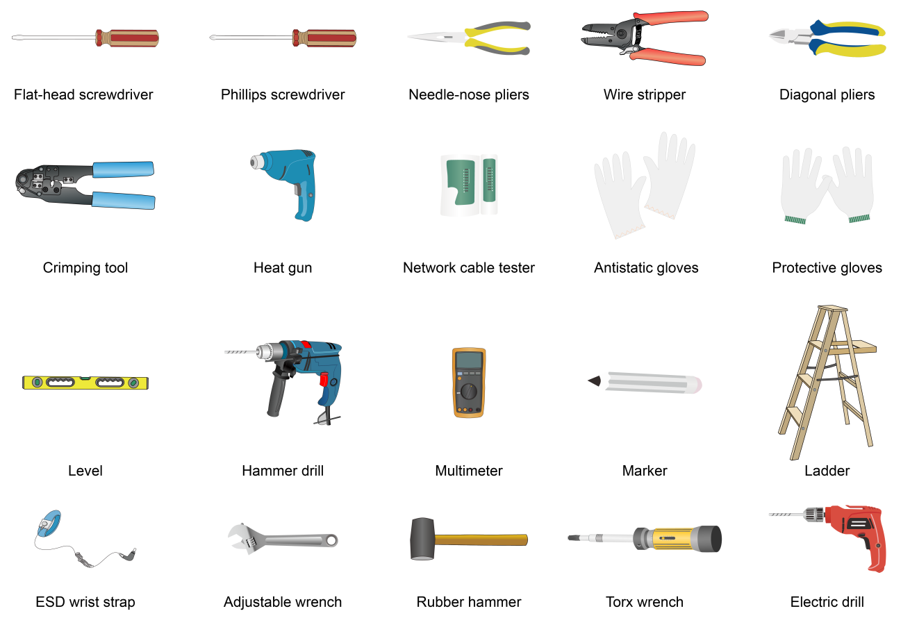
Installation tools
No installation tools are provided with the device. Prepare the tools yourself as required.
Installation accessories
Overview
Table2-4 Installation accessories
|
Installation accessories |
Illustration |
Quantity |
Description |
|
Mounting bracket |
|
One provided Product code: 9821A06P |
Ceiling mounting accessory |
|
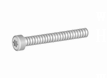
Anti-theft screws |
|
One provided Specifications: M3×23.5mm |
Used with mounting brackets |
|
Expansion screws and bolts |
|
Three provided Screw specifications: · Diameter:4mm · Length:25mm(excluding the thickness of the screw head) |
Used with mounting brackets |
|
Flat head screws |
|
Three provided Specifications: M3×30mm |
Used with mounting brackets |
|
Power Adapter |
|
Optional Product code: FSP025-1AD207A |
Used with local power supply |
|
AC power cord |
|
Optional Product code: 0404A06Q, 04041104 |
Used with power adapter for local power supply |
|
PoE injector |
|
Optional Product code: 9802A035 |
Used with PoE power supply |
|
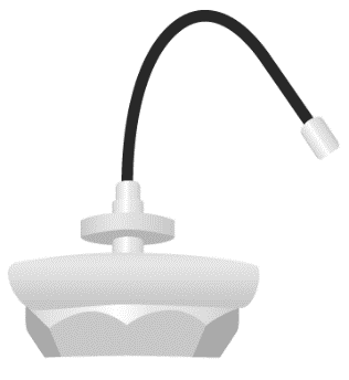
External antenna |
|
Optional Product code: 2701A01T |
Used with external Wi-Fi antenna |
|
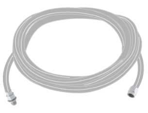
5m Feed Line |
|
Optional Product code: 0404A0FS |
Used with external antenna |
|
Jumper |
-- |
Optional Product code: N/A |
Used with external antenna |
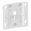


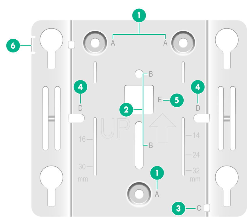
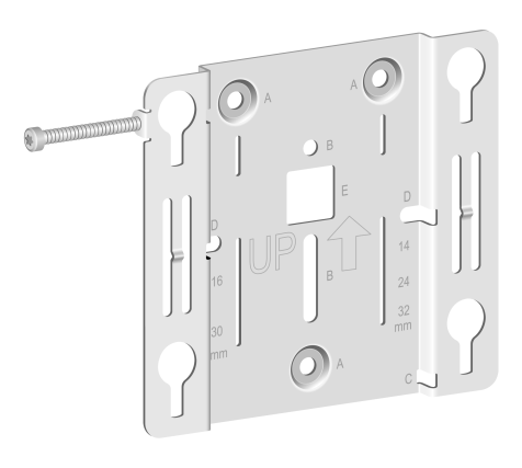
Mounting bracket
Figure2-1 Mounting bracket
|
1: (Point A) Mounting hole for ceiling installation to secure the mounting piece to the ceiling |
2: (Point B) Reserved joist mounting hole, supporting joist mounting method (currently not supported) |
|
3: (Point C) Auxiliary cable fixation hole, use zip ties to secure the cable at point C |
4: (Point D) Reserved 86 faceplate mounting hole, supporting 86 faceplate mounting method (currently not supported) |
|
5: (Point E) Pass the cable through point E to connect to the CPE |
6: Anti-theft hole, compatible with anti-theft screws (M3 x 23.5mm) |
3 Installing the device
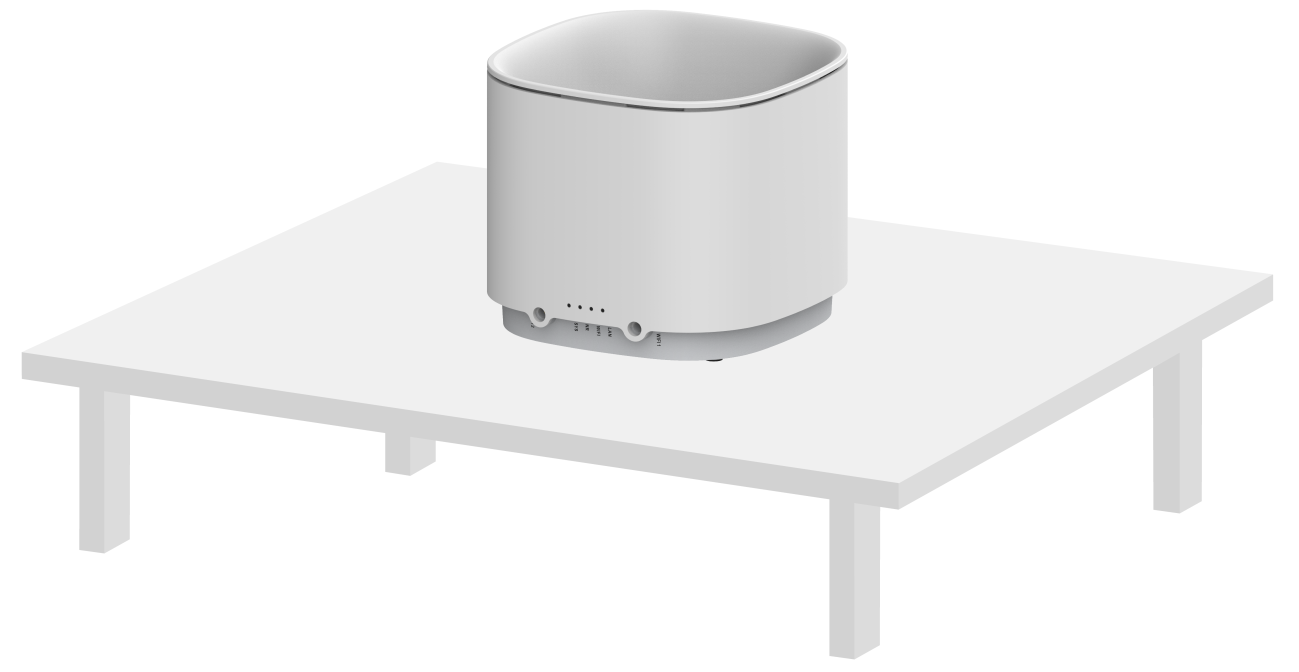
Installing device to desktop
Be careful to place the device upright on a clean, stable workbench.
Figure3-1 Installing device to desktop
Ceiling-mounting the device
Mounting the device to a cement ceiling
|
|
NOTE: · The cement roof needs to be able to withstand 4 times the weight of the device without being corrupted. · It may be inconvenient to install the SIM card after the device is mounted on the ceiling, so if necessary, the SIM card can be installed in advance. |
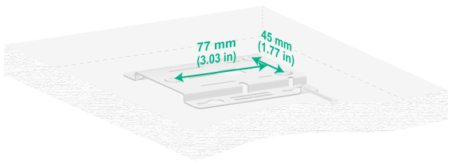
1. Mount the installation piece on the cement ceiling, marking the positions where the mounting screws need to be installed.
Figure3-2 Mark the installation position
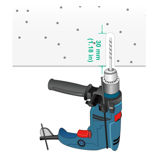
2. Use a hammer drill to drill three 6mm diameter holes at the marked locations, ensuring that the drilled holes correspond to the mounting points on the mounting kit.
Figure3-3 Drilling holes on the wall
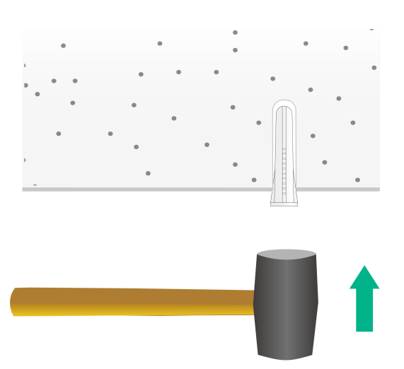
3. Use a rubber hammer to tap the expansion screw into the mounting point until it is level with the cement, as shown in Figure3-4.
Figure3-4 Securing the screw anchors
4. Hang the anti-theft screw on the anti-theft hole of the mounting part, and be careful not to screw it in too far from the edge of the gourd hole.
Figure3-5 Install anti-theft bolts
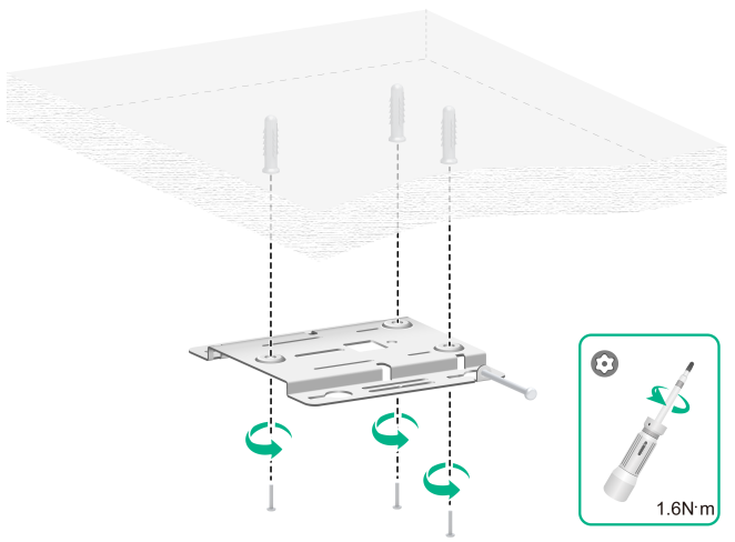
5. Pass the screws matching the expansion screw through the corresponding mounting holes, adjust the position of the mounting part, use a screwdriver to tighten the screws in a clockwise direction, and secure the main mounting part to the concrete ceiling.
Figure3-6 Install the fixed mounting bracket onto the cement ceiling
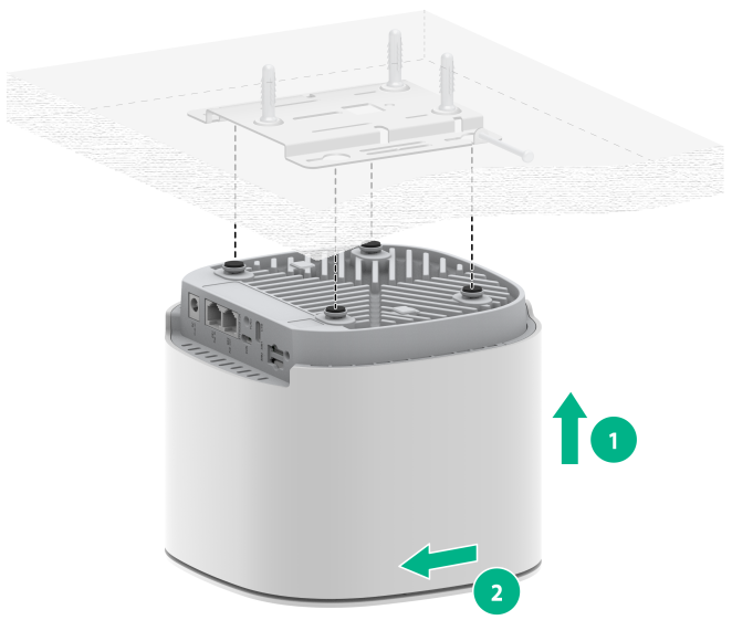
6. Align the screws on the back of the device with the gourd holes on the mounting piece, insert the screws and hooks into the gourd holes of the main mounting piece, then push the device horizontally along the opposite direction of the UP arrow on the main mounting piece to hang the device on the main mounting piece.
|
|
IMPORTANT: Before fixing the equipment, please confirm whether it is necessary to connect the device cables in advance to prevent insufficient space from causing inconvenience or even preventing the cables from being connected. |
Figure3-7 Secure the device to the mounting bracket
7. Use an internal hexagon screwdriver to tighten the anti-theft M3 x 23.5 screw. Clockwise tighten the limit screw on the main installation part to lock the hook and prevent the device from slipping off. The screw depth should be adjusted so that the limit screw is not visible from the front of the device.
Figure3-8 Install anti-theft bolts
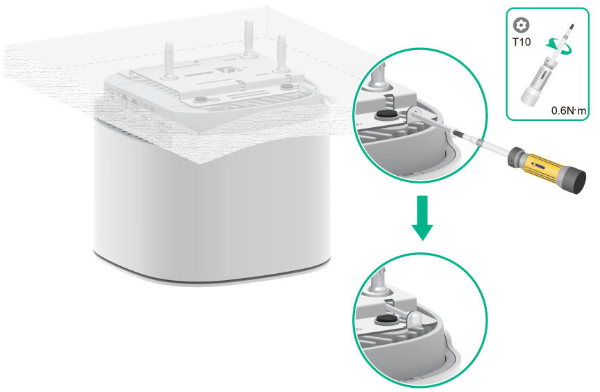
|
|
IMPORTANT: Verify that the device is installed securely to prevent it from falling off. |
Installing the device to ceiling
|
|
IMPORTANT: · Ceiling installation requires the thickness of the ceiling to be less than 18mm, and the ceiling must be able to support at least 5kg of weight. · If the material itself, such as gypsum ceiling, has weak strength, this installation method is not recommended. If this installation method must be used due to environmental limitations, an additional layer of stronger material should be added under the nut to ensure the device is securely installed. · It may be inconvenient to install the SIM card after the device is ceiling-mounted. If necessary, the SIM card can be installed in advance. |
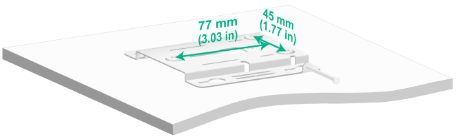
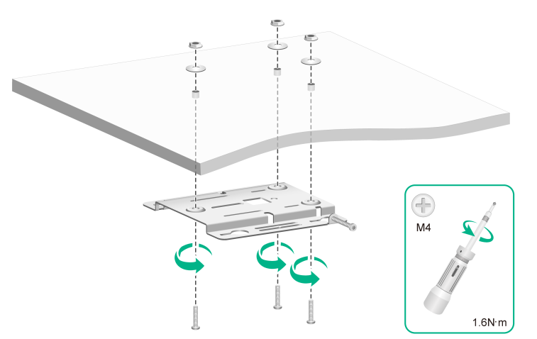
1. Remove the ceiling, attach the mounting parts to the ceiling, and use a marker to mark the drilling positions on the ceiling.
Figure3-9 Mark installation location
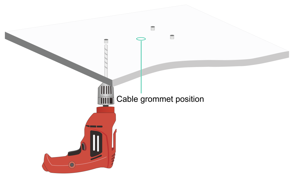
2. Use a flashlight to drill three 4.5mm diameter holes at the marked locations, ensuring that the drilled holes correspond to the mounting points on the installation kit. It is important to note that if cable runs are required within the ceiling, additional cable run holes should be drilled according to the position of point E on the mounting bracket.
Figure3-10 Drill holes in the ceiling
3. Hang the anti-theft bolt on the anti-theft hole of the mounting part, and be careful not to screw it in beyond the edge of the gourd hole.
Figure3-11 Install anti-theft bolts

4. Thread the countersunk head screw through the mounting holes on the mounting piece and the drilled holes on the ceiling, and use a nut and gasket to tighten the bolt at the other end of the ceiling, securing the mounting piece to the ceiling.
Figure3-12 Fixed mounting bracket
5. Align the screws on the back of the device with the gourd holes on the mounting bracket, insert the screws into the gourd holes of the main mounting bracket, then push the device horizontally along the opposite direction of the UP arrow on the main mounting bracket, and hang the device on the main mounting bracket.
|
|
IMPORTANT: Before fixing the equipment, please confirm if you need to connect the device cable in advance to prevent insufficient space from causing inconvenience or even inability to connect the cable. |
Figure3-13 Installing the device
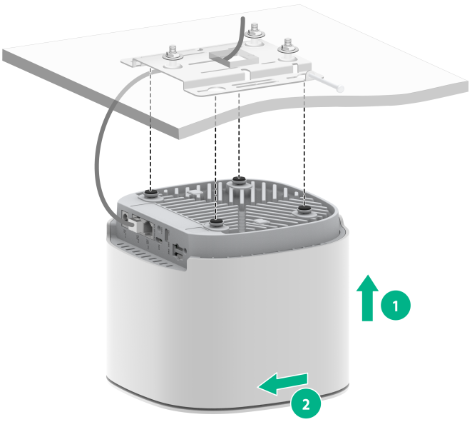
6. (Optional) Use the auxiliary fixed cable hole to secure the cable.
¡ The cable ties are not randomly attached, please prepare them yourself.
¡ When installing on the ceiling, before fixing the device to the mounting bracket, please use cable ties to pass through the auxiliary cable fixing hole to secure the Ethernet cable, making sure not to tighten the cable ties; then pull and adjust the length of the cable, tighten the cable ties; finally, fix the device to the mounting bracket.
Figure3-14 Fixed All-in-one cable

|
|
IMPORTANT: Verify that the device is installed securely to prevent it from falling off. |
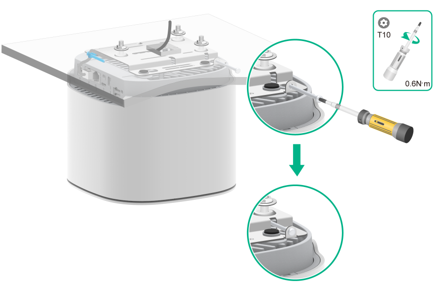
7. Tighten the anti-theft screws with an internal hexagon screwdriver.
Figure3-15 Install anti-theft bolts
4 Connecting cables
Connecting power
|
|
IMPORTANT: · After you install the CPE, perform the following tasks each time before you power on the AP: · When the CPE is powered locally, please acknowledge that the local AC power is well grounded. · When you power the CPE over PoE, make sure the PoE power supply device is reliably grounded. · Examine the LEDs on the device after you power it on to verify that the device is operating correctly. For more information about the LEDs, see the hardware information and specifications. |
The device supports local power supply and PoE power supply, and users can choose the power supply method according to the actual network environment.
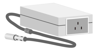
Local power supply
|
|
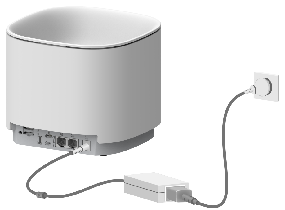
NOTE: The power adapter is not randomly included. If the device is powered locally, it is recommended to purchase the power adapter specified by H3C. |
Connect the device's power interface to the local power supply through a power adapter to achieve local power supply.
Figure4-1 Connection power adapter illustration
PoE power supply
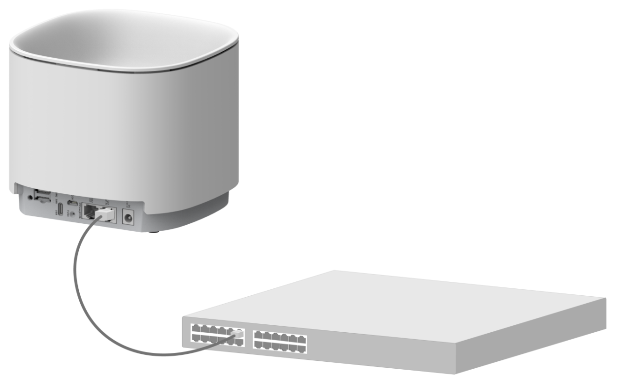
Powering through a switch
Use an Ethernet cable to connect the device's Ethernet interface (GE1/PoE_IN interface) to a PoE-enabled switch, enabling PoE power supply.
Figure4-2 Power the device over PoE
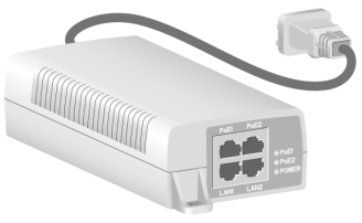
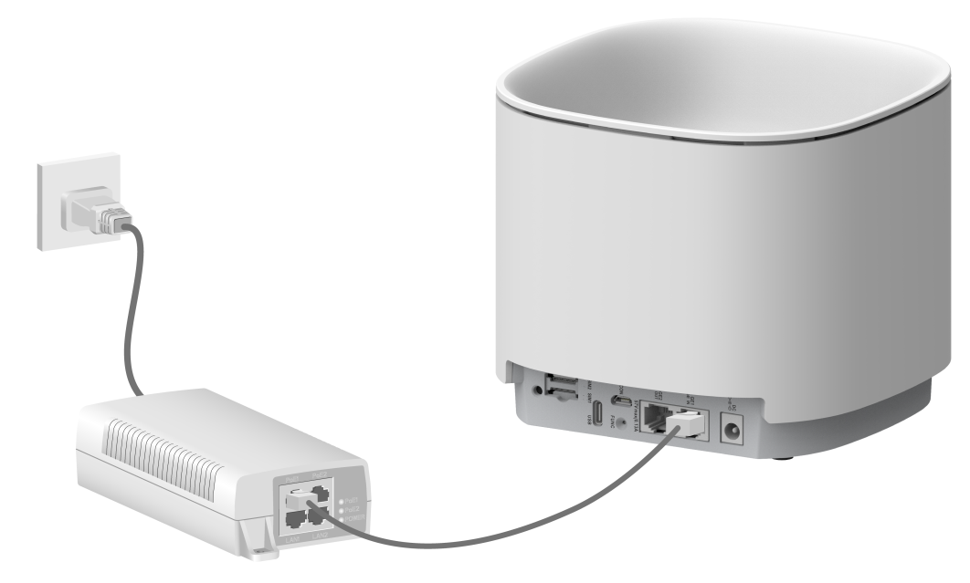
Powering through a PoE power injector
|
|
NOTE: Power injectors are not included randomly. If the device uses a power injector for PoE power supply, it is recommended to purchase the power injector specified by H3C. |
When using the power injector method to power the device, the connection steps are as follows:
1. Connect the Ethernet interface of the connecting device to the PoE1 interface of the power injector (GE1/PoE_IN interface);
2. Connect the power injector to the AC power source.
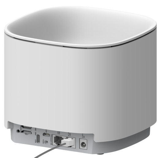
Connecting an Ethernet cable
1. Insert one end of the Ethernet cable into the GE1/PoE_IN port or the GE2/PoE_OUT port.
2. After power on, please check the status of the Ethernet interface status indicator light to see if it is normal.
Figure4-3 Connecting an Ethernet cable
6 Installing the SIM card
|
|
IMPORTANT: · The SIM card is not provided by default; users can purchase one based on their actual needs. · The device offers two SIM card slots, supporting automatic switching between SIM cards. · When installing or removing a SIM card, please ensure the device is powered off to guarantee its normal operation. · When handling the SIM card, do not touch the components. · If the SIM card is not being installed, please fit the dust cover to prevent dust or foreign objects from entering the device and causing electrostatic adhesion or damage. |
The CPE has 2 SIM card interfaces, supporting automatic SIM card switchover. When the device is powered on, it first detects and uses the primary SIM card. If the primary SIM card is not detected, it switches to the backup SIM card slot and continues to use the backup SIM card within the current power cycle. The CPE supports Nano SIM card types. The specific steps are as follows:
1. Open the dust cover of the SIM card slot.
2. Slowly push the SIM card along the card slot guide rail until it is fully inserted.
Figure6-2 Inserting the SIM card
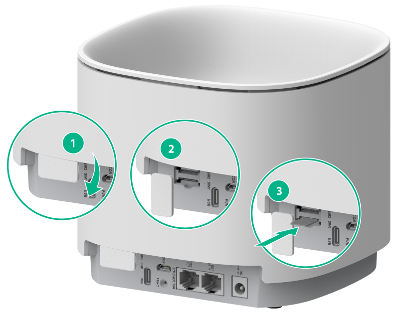
3. Put on the dust cover of the SIM card slot.
7 Verifying the installation
Basic check items
Table7-1 Basic check items
|
No. |
Check items |
|
1 |
Check whether the selected power supply matches the device's power identification |
|
2 |
The power cords are correctly connected. |
|
3 |
If part of the network cable for a port is routed outdoors, verify that a network port lightning protector is used for the port. If a power line is routed from outdoors, verify that a surge protected power strip is used for the device. |
Checking the ceiling for installation
Table7-2 Ceiling check items
|
No. |
Check item |
|
1 |
Check if the ceiling position of the equipment matches the design drawing |
|
2 |
Check if the cement ceiling or ceiling is firm |
|
3 |
Check if the screws are tightened and if the anti-theft screws are in place |
|
4 |
Check for any other improper or even dangerous installation practices, such as directly tying the equipment or installation parts with plastic ties, and rectify immediately if found |
|
5 |
Check if the environment where the equipment is located is clean, and if there is dust, garbage, etc., it needs to be cleaned up in time |
|
6 |
Check if there is enough space around the equipment |
8 Device initial power on and startup
|
|
NOTE: By default, the device operates in fit mode. You can switch the operating mode of the CPE5100P between fit and cloud as needed. |
When the device is powered on for the first time, you can directly log in to the device through the console port. Local login through the console port is the basic login method and basis of other login methods. To remotely log in to the device through Telnet or the web interface, you must first obtain the IP address of the device. Remote login through the web interface is supported only when the device operates in cloud mode.
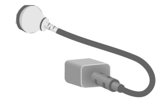
Local login through the CONSOLE port
Setting up the environment
|
|
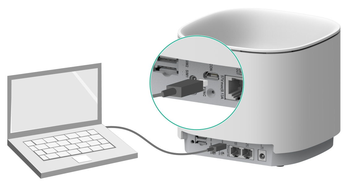
NOTE: · The device provides console access through the CON interface (i.e. Mini USB Console port) and requires connection through a USB configuration cable. · Before configuring the device, you need to download and install the USB Console driver from the official H3C website www.h3c.com. |
1. Connect the USB interface end to the PC.
2. Connect the other end to the CON interface of the device.
Figure8-1 Connecting device through USB all-in-one cable
3. Download the driver and install it. Please contact H3C sales personnel or technical support personnel for the driver.
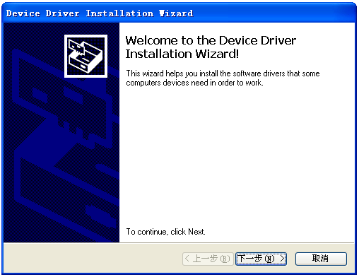
4. On the welcome page of the installation wizard, click Next button. The following pages are for reference only.
Figure8-2 Installation wizard welcome page
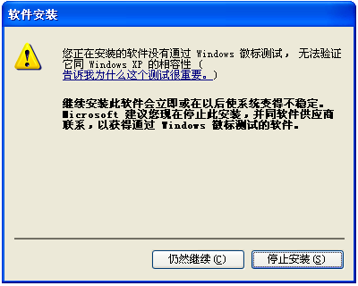
5. If the prompt shown in the following image appears, select to continue.
Figure8-3 Install compatibility page
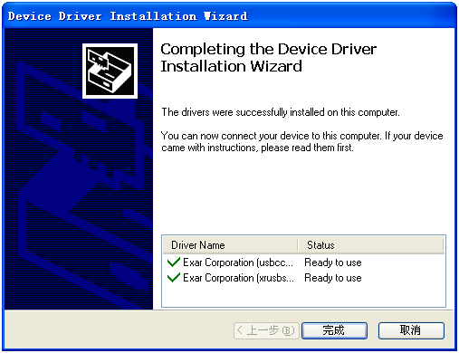
6. The driver installation is complete, click Finish button, exit the wizard.
Figure8-4 Installation wizard completion page
Configuring terminal parameters
To set up a local configuration environment through the console port, you must use a terminal emulation program, such as HyperTerminal or PuTTY, to establish a connection with the router. You can run terminal emulation programs to connect to network devices or access sites through Telnet or SSH. For more information about how to use terminal emulation programs, see the programs' user guides.
Configure the terminal parameters as follows:
Baud rate—9600.
Data bits—8.
Stop bits—1.
Parity—None.
Flow control—None.
Logging in to the device through the CONSOLE port
After the device is powered on, the PC terminal screen displays the following information:
System is starting...
Booting Normal Extend BootWare.
……
System application is starting...
Startup configuration file does not exist.
User interface con0 is available.
Press ENTER to get started.
Logging in to the device through Telnet
By default, Telnet is enabled on the device, and the default login information is as follows:
· Username: admin
· Password: h3capadmin
· Management IP address (non-FIT mode): 192.168.8.1/24
|
|
NOTE: · By default, interface VLAN-interface 1 of the device can obtain an IP address through DHCP. When a DHCP server is deployed in the network, the CPE preferentially obtains an IP address through DHCP. · If the device operates in cloud mode and cannot obtain an IP address automatically, the device uses 192.168.8.1/24. · To view the IP address of interface VLAN-interface 1, log in to the device through the console port, and then execute the display ip interface brief command in any view. |
Logging in to the device through wired connection
By default, you can log in to the device through a wired network when the device operates in fit or cloud mode.
To log in to the device through a wired network by using the default login information:
1. Connect the maintenance endpoint to the GE1/PoE_IN or GE2/PoE_OUT port on the device.
2. Configure an IP address for the maintenance endpoint, and make sure the maintenance endpoint and interface VLAN-interface 1 on the device can reach each other.
3. On the maintenance terminal, start the terminal emulation program (such as HyperTerminal or PuTTY), select the Telnet option, and then enter the device's management IP address, username, and password.
Logging in to the device wirelessly
|
|
NOTE: Configure the wireless client to dynamically obtain an IP address. Some Intel NICs might not be compatible with the 802.11ax mode. To successfully detect Wi-Fi 6 wireless networks, upgrade the NIC drivers to the latest version as a best practice. For more information, see the related document at the Intel offcial website. |
By default, you can log in to the device through a wireless network when the device operates in cloud mode.
To log in to the device through a wireless network by using the default login information:
1. Enable Wi-Fi on the wireless client. Search for and connect to the Wi-Fi named H3C_WiFi_1.
2. Execute the telnet wlan.h3c.com command on the CLI of the wireless terminal.
3. Enter the default username and password, and change the password as needed upon prompt.
Logging in to the device through the web interface
|
|
NOTE: You can log in to the device through the web interface only when the device operates in cloud mode. |
The device supports both HTTP and HTTPS.
By default, HTTP and HTTPS are enabled on the device, and the default login information is as follows:
· Username: admin
· Password: h3capadmin
· User role: network-admin
· Management IP address (non-FIT mode): 192.168.8.1/24
|
|
NOTE: · By default, interface VLAN-interface 1 of the device can obtain an IP address through DHCP. When a DHCP server is deployed in the network, the CPE preferentially obtains an IP address through DHCP. · If the device operates in cloud mode and cannot obtain an IP address automatically, the device uses 192.168.8.1/24. · To view the IP address of interface VLAN-interface 1, log in to the device through the console port, and then execute the display ip interface brief command in any view. |
Logging in to the web interface through a wired connection
To log in to the device web interface through a wired network by using the default login information:
1. Connect the maintenance endpoint to the GE1/PoE_IN or GE2/PoE_OUT port on the device.
2. Configure an IP address for the maintenance endpoint, and make sure the maintenance endpoint and interface VLAN-interface 1 on the device can reach each other.
3. On the maintenance endpoint, enter the management IP address of the device in the address bar of a browser, and press Enter to access the local web management interface of the device. If HTTP is used, the URL is in the http://ip-address:80 format, where http:// can be omitted. If HTTPS is used, the URL is in the https://ip-address:443 format. ip-address represents the management IP address of the device. Port numbers 80 and 443 are the default port numbers for HTTP and HTTPS, respectively, and can be omitted.
4. Click Log In. Change the login password upon the prompt as needed, and then click OK.
Logging in to the web interface wirelessly
|
|
NOTE: By default, Wi-Fi service with SSID H3C_WiFi_1 is enabled on the device. Some Intel NICs might not be compatible with the 802.11ax mode. To successfully detect Wi-Fi 6 wireless networks, upgrade the NIC drivers to the latest version as a best practice. For more information, see the related document at the Intel offcial website. |
To log in to the device web interface through a wireless network by using the default login information:
1. Enable Wi-Fi on the wireless client. Search for and connect to the Wi-Fi named H3C_WiFi_1, where XXXXXX is the last six digits of the device's MAC address.
2. On the wireless endpoint, enter http://wlan.h3c.com in the address bar of a browser, and then press Enter to open the device login page.
3. Enter the default username and password, and then click Log In. Change the login password as needed upon the prompt, and then click OK.
Logging out of the web interface
For security purposes, log out of the web interface immediately after you finish your tasks.
To log out of the web interface, click admin on the top right of the page, and then select Log Out.
The system does not save the running configuration automatically when you log out of the web interface. As a best practice, use either of the following methods to save the running configuration before logging out of the web interface:
· Click Save on the top right of the page, and then click Yes in the dialog box that opens.
· From the left navigation pane, select System > Management > Configuration. Click Save Running Configuration, select to the next-startup configuration file, and then click Apply.
9 Managing the device through Cloudnet
You can manage a device through Cloudnet only when the device operates in cloud mode.
Downloading and installing the Cloudnet app
Use an Android 4.0/iOS7.0 or above operating system to download the Cloudnet app.
Access https://cloudnet.h3c.com through a browser, use a phone to scan the QR code on the login page to download and install the Cloudnet app.
Logging in to Cloudnet
|
|
IMPORTANT: For the device to access Cloudnet, make sure the IP address of the device can reach the Internet. |
After you connect the device to the public network, log in to Cloudnet, add the device to the device list at a specific site on Cloudnet, and then view and manage the device remotely. For more information about logging in to Cloudnet, adding sites, and adding devices, see H3C Cloudnet Deployment Guide.
1. Log in to Cloudnet by using either of the following methods:
¡ Web login—Access https://cloudnet.h3c.com in a browser, and then enter the username and password on the login page.
¡ Mobile app login—Connect your phone to the network, open the Cloudnet APP, and then enter the username and password on the login page.
2. Add the device.
For detailed information, see H3C Cloudnet Deployment Guide from the Cloudnet online documentation.
