- Table of Contents
- Related Documents
-
| Title | Size | Download |
|---|---|---|
| 01-Text | 1.71 MB |
Hardware information and specifications
About the H3C 5G extended pico station
Chassis views and technical specifications
NR main control and baseband module
About the NR main control and baseband module
Ports on the NR main control and baseband module
Hardware information and specifications
About the H3C 5G extended pico station
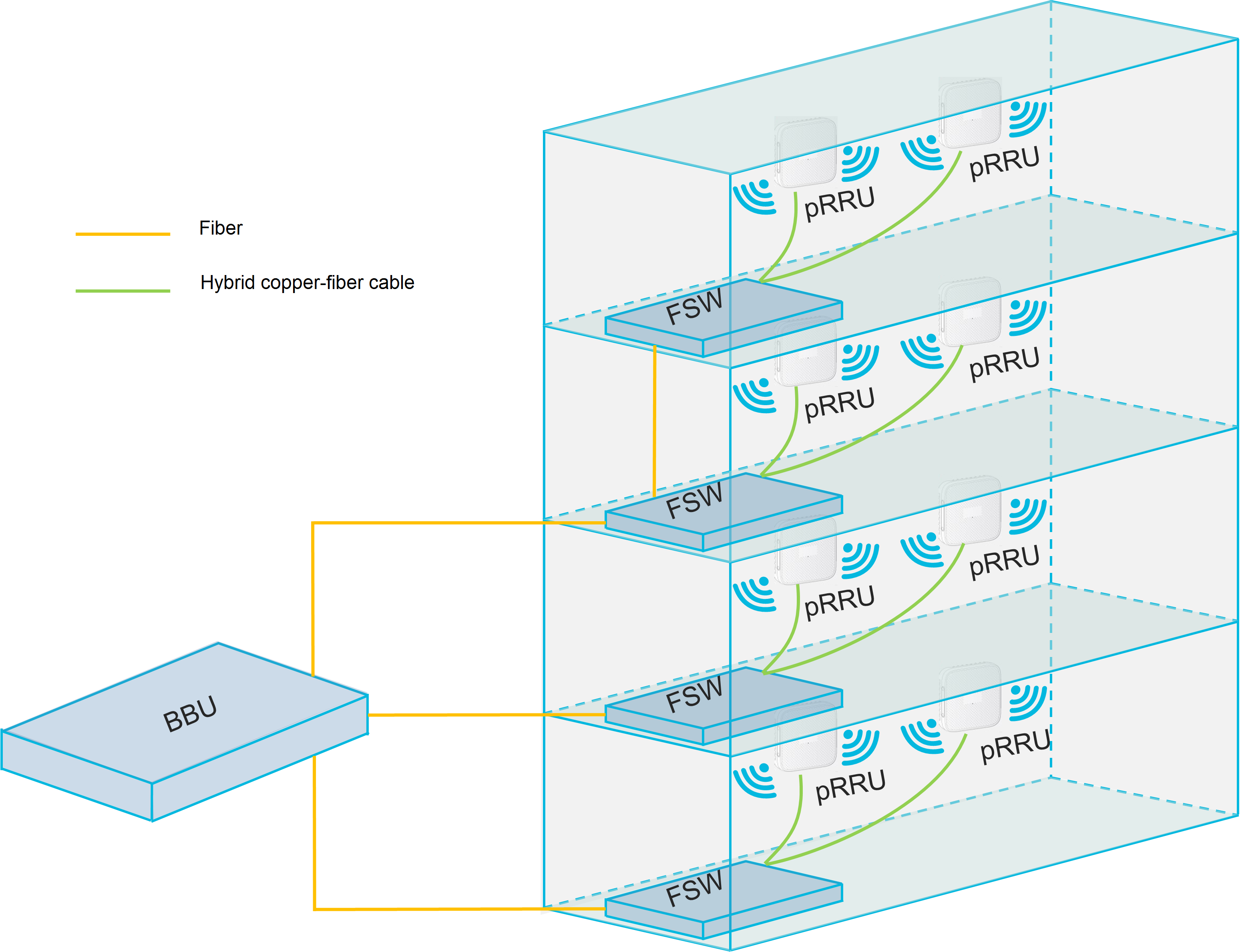
An H3C 5G extended pico station is an indoor distributed wireless access system, featuring simple architecture, ease of deployment, low maintenance, and deep multi-standard coverage. As shown in Figure 1, an H3C extended pico station contains three parts:
· BBU—Baseband processing unit for the 5G extended pico station, providing device management, configuration management, performance monitoring, clock management, signaling processing, baseband resource management, and wireless resource management.
· FSW—Extension unit of the 5G extended pico station. It connects to the BBU or subordinate FSW through fiber and accesses the pRRU through a hybrid copper-fiber cable to provide power.
· pRRU—Radio frequency remote unit for the 5G extended pico station, providing the following features:
¡ The transmit channel receives digital signals from the BBU enhanced Common Public Radio Interface (eCPRI) port, performs digital-to-analog conversion, frequency modulation, and amplification filtering, and ultimately transmits the RF signal through the antenna.
¡ The receive channel captures the RF signal from the antenna, amplifies and filters it, performs frequency modulation, converts it to a digital signal, and sends it back to the BBU through the eCPRI port.
The pRRU can be directly connected to the BBU or extended through the FSW to expand the cell scale.
Figure 1 H3C 5G extended pico station
Chassis views and technical specifications
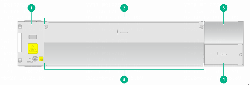
Chassis views
|
|
NOTE: The rear panel has no special markings, and this manual does not provide further details. |
|
1: Fan tray |
2: SLOT0 |
|
3: Power module slot (PWR0) |
4: Power module slot (PWR1) |
|
5: SLOT1 |
|
|
|
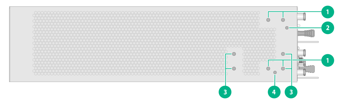
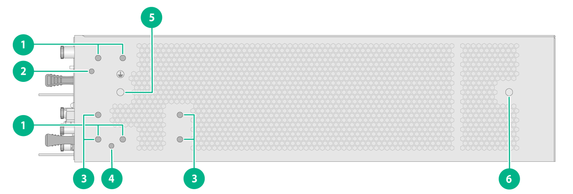
NOTE: Some mark information on the upper part of the device is not shown in the figure. |
Figure 3 Side panel
|
(1): Ear mounting position (used when mounting to a rack) |
(2): Ear alignment pin hole position (used when mounting to a rack) |
|
(3): Ear mounting position (used when mounting to a wall) |
(4): Ear alignment pin hole position (used when mounting to a wall) |
|
(5): Main grounding point of the device (near the power side) |
(6): Auxiliary grounding point of the device (near the power side) |
Technical specifications
Table 1 Hardware specifications
|
Item |
BBU5200 |
|
Installation method |
Can be installed to a 19-inch rack or to a wall |
|
Dimensions (W × D × H) |
440 × 333 ×88 mm |
|
Weight |
Fully configured weight ≤ 11.6 kg |
|
Heat dissipation |
≤ 200 W |
|
Typical power consumption |
· DC ≤ 215 W · AC: ¡ Active power ≤ 215 W ¡ Apparent power ≤ 239 W |
|
Baseband module slot |
Two at slots 0 and 1 on the front panel. · Slot 0 supports the NR baseband module with product code MCBM1NBBPD1. · Slot 1 supports the NR baseband module with product code MCBM1NBBPD1. |
|
Power module slot |
Two at the front panel. Support the PSR780-12A, PSR780-12D, and PSR255-12A power modules. |
|
Fan tray slot |
One at the front panel |
|
Temperature |
· Operating: -5°C to 55°C · Non-operating: -40°C to 70°C |
|
Relative humidity (non-condensing) |
· Operating: 5% to 95% · Non-operating: 0% to 100% |
Power modules
About power modules
BBU5200 supports the PSR780-12A, PSR780-12D, and PSR255-12A power modules.
|
|
IMPORTANT: BBU5200 does not support mixed use of DC and AC power modules. |
PSR780-12A AC power module
Figure 4 shows the PSR780-12A AC power module appearance.
Figure 4 PSR780-12A AC power module
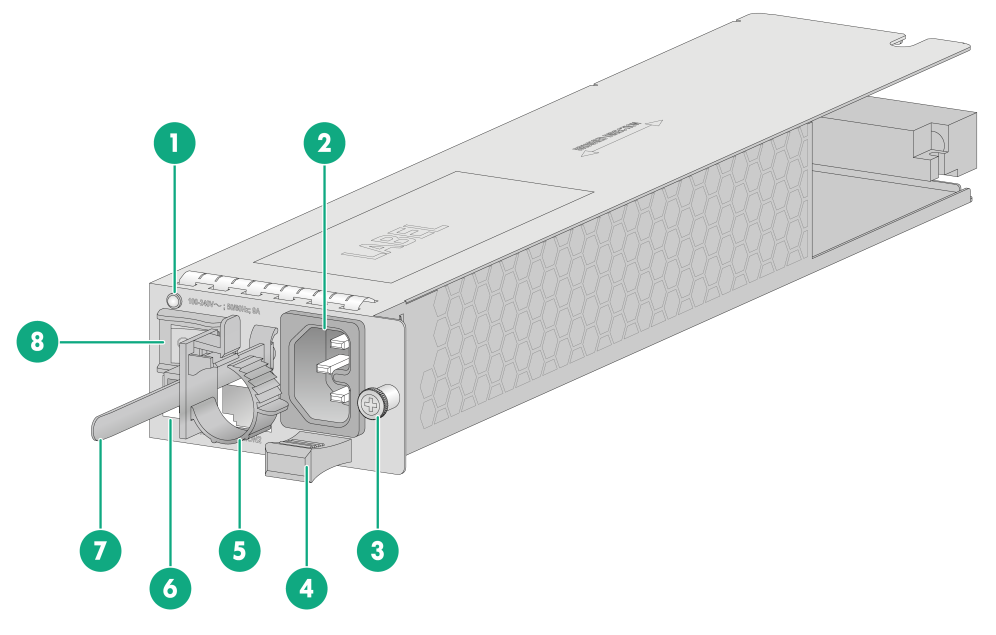
|
1: Status LED |
2: Power input socket |
|
3: Screw |
4: Cable tie holder |
|
5: Cable clamp |
6: Environment monitoring port (MON) |
|
7: Mounting strap |
8: Power switch |
Table 2 PSR780-12A AC power module specifications
|
Model |
Item |
Specifications |
Description |
||
|
PSR780-12A |
Input rated voltage range |
100 V to 240 V AC, 50/60 Hz |
For more information about the power module, see H3C PSR780-12A Power Module User Manual. BBU5200 does not support sending environmental information of the device to the environment monitor through the MON port of the power module. |
||
|
Input maximum voltage range |
90V to 290V AC, 45 to 65 Hz |
|
|
||
|
Power fuse blow current |
12.5 A |
|
|
||
|
Maximum power supply capacity |
780 W |
|
|
||
|
Number and type of interfaces |
Two MON ports |
|
|
||
|
Cable types supported by interface |
MON port supports cables listed in Table 5. |
|
|
||
PSR780-12D DC power module
Figure 5 shows the PSR780-12D DC power module appearance.
Figure 5 PSR780-12D DC power module
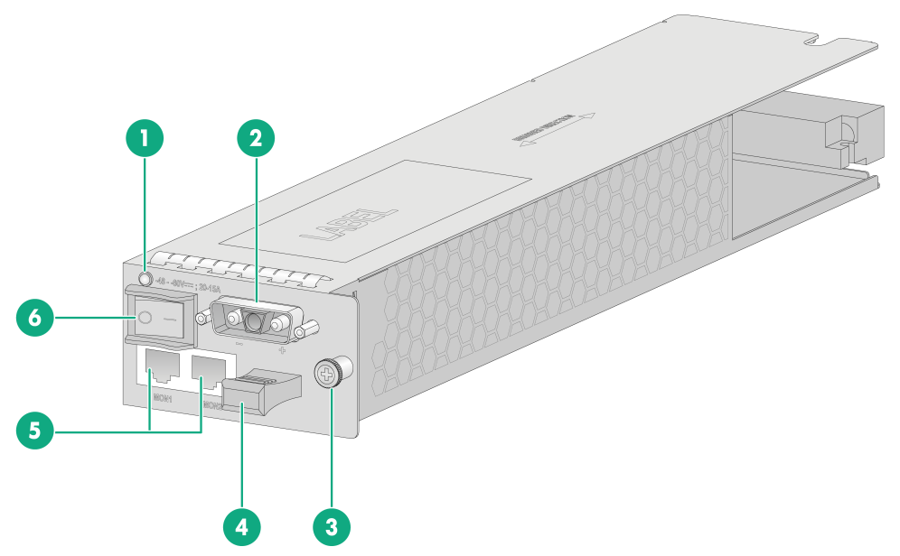
|
1: status LED |
2: Power input socket |
|
3: Screw |
4: Cable tie holder |
|
5: Environment monitoring port (MON) |
6: Power switch |
Table 3 PSR780-12D DC power module specifications
|
Model |
Item |
Specifications |
Description |
|
PSR780-12D |
Input rated voltage range |
-48 to -60 VDC |
For more information about the power module, see H3C PSR780-12D Power Module User Manual. BBU5200 does not support sending environmental information of the device to the environment monitor through the MON port of the power module. |
|
Input maximum voltage range |
-36 to -72 VDC |
||
|
Power fuse blow current |
30A |
||
|
Maximum power supply capacity |
780W |
||
|
Number and type of interfaces |
Two MON ports |
||
|
Cable types supported by the interface |
MON port supports cables listed in Table 5. |
PSR255-12A AC power module
Figure 6 shows the PSR255-12A AC power module appearance.
Figure 6 PSR255-12A AC power module
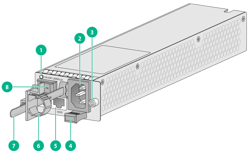
|
1: status LED |
2: Power input socket |
|
3: Screw |
4: Cable tie holder |
|
5: Environment monitoring port (MON) |
6: Cable clamp |
|
7: Mounting strap |
8: Power switch |
Table 4 PSR255-12A AC power module specifications
|
Model |
Item |
Specifications |
Description |
|
PSR255-12A |
Input rated voltage range |
100V to 240V AC, 50/60 Hz |
For more information about the power module, see H3C PSR255-12A Power Module User Manual. BBU5200 does not support sending environmental information of the device to the environment monitor through the MON port of the power module. |
|
Input maximum voltage range |
90V to 290V AC, 45 to 65 Hz |
||
|
Power fuse blow current |
6.3A |
||
|
Maximum power supply capacity |
255W |
||
|
Number and type of interfaces |
Two MON ports |
||
|
Cable types supported by the interface |
MON port supports cables listed in Table 5. |
MON ports
The front panel of each power module provides two MON ports, which can be interconnected with the ports on an environment monitor through RJ-45 twisted pair cables. The attributes of the MON ports and the supported cable types are shown in Table 5.
|
|
NOTE: BBU5200 does not support sending environmental information of the device to the environment monitor through the MON port of the power module. |
Table 5 Attributes of the MON ports and the supported cable types
|
Item |
Description |
|
RJ-45 |
|
|
Category 6 or above shielded twisted pair cable |
|
|
Cable attributes |
· Cable 1/3/5/7 is connected to the alarm signal input interface of the environment monitor. · Cable 1/2/4/5 is connected to the RS485 monitoring signal input interface of the environment monitor. |
Power module status LED
The operational status of the power module can be identified through the status LED on the front panel.
|
|
NOTE: The LED description is the same for AC and DC power modules. |
Table 6 Pluggable power module LED state
|
LED state |
Description |
|
Steady green |
Power module runs correctly. |
|
Flashing green (0.5 Hz) |
The power module has current input (the power module input is normal, but there is no 12 V output. In this case, the LED of the power module will be flashing green). |
|
Steady red |
The power module fails or enters the protection state. |
|
Alternatively flashing red and green (0.5 Hz) |
The power module generates an alarm. The power module has experienced conditions such as output overcurrent, output power overload, overtemperature, but has not entered the protection state. |
|
Flashing red (0.5 Hz) |
The power module has no current input. If the device is installed with two power modules and one has current input while the other does not, the LED of the power module without current input will be flashing red. Under-voltage input protection. |
|
Off |
The power module has no current input or has entered the 3.3 V output short circuit protection state. |
Fan trays
About fan trays
|
|
NOTE: The device supports a variety of fan tray models, and different device versions might come with different types of fan trays. This document takes FAN-80-3-C as an example. |
Figure 7 shows the fan tray appearance.
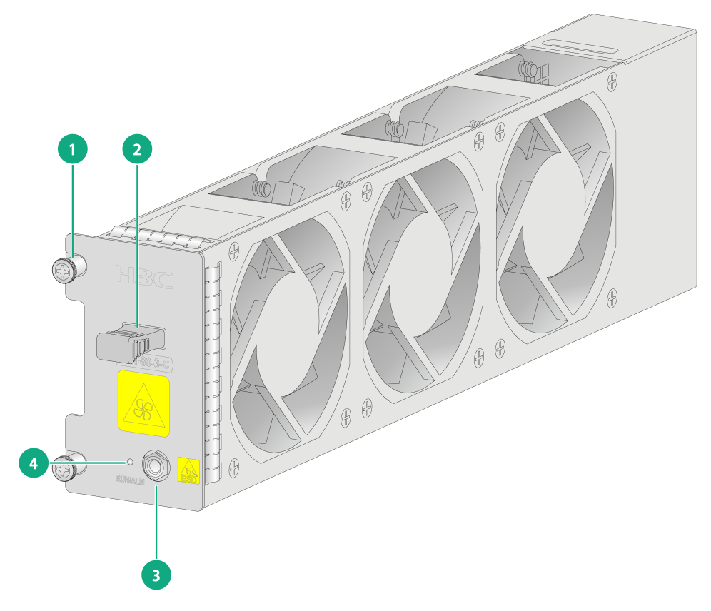
|
1: Screw |
2: Cable tie holder |
|
3: ESD jack |
4: Fan status LED |
Table 7 Fan tray specifications
|
Fan tray model |
Item |
Specifications |
|
FAN-80-3-C |
Maximum fan speed |
9900 rpm/min |
|
Maximum airflow |
105.21 cubic feet/min |
|
|
Operating voltage |
10.2 V to 13.2 V |
|
|
Maximum power consumption |
49.68 W |
Fan tray status LED
The operational status of the fan tray can be identified through the status LED on the front panel.
Table 8 Pluggable fan tray LED state
|
LED state |
Description |
|
Steady green |
Fan tray runs correctly |
|
Steady red |
Fan tray is abnormal |
|
Off |
Fan tray is removed or powered off |
NR main control and baseband module
About the NR main control and baseband module
MCBM1NBBPD1 is the NR baseband module for a 5G base station BBU, providing device management, configuration management, performance monitoring, clock management, signaling processing, baseband resource management, and wireless resource management.
Figure 8 NR baseband module

|
(1) Screw |
(2) NR baseband module system status LEDs (RUN, ALM, and ACT) |
|
(3) GNSS port |
(4) USB port |
|
(5) MANAGEMENT port status LED (left ACT, right LINK) |
(6) 1PPS+TOD port (OUT) |
|
(7) SFP+ uplink port |
(8) eCPRI downlink port |
|
(9) eCPRI downlink port status LED |
(10) SFP+ uplink port status LED |
|
(11) 1PPS+TOD port (IN) |
(12) CONSOLE port |
|
(13) MANAGEMENT port |
(14) RESET button |
|
(15) Wrench |
|
Table 9 NR baseband module specifications
|
Item |
Specifications |
|
Applicable models |
MC-BBU5200 |
|
Operating frequency band |
· 2515 MHz to 2675 MHz · 3300 MHz to 3600 MHz · 4800 MHz to 4900 MHz |
|
Duplex mode |
TDD |
|
Weight |
2.36 kg |
|
Ports |
1 GNSS port |
|
1 USB port |
|
|
1 MANAGEMENT port |
|
|
1 CONSOLE port |
|
|
2 1PPS+TOD ports |
|
|
2 SFP+ uplink ports |
|
|
4 eCRPI downlink ports |
|
|
Reset button |
1 RESET button. You can press and hold this button for one second to reboot the NR baseband module. |
|
Temperature |
· Operating: -5°C to 55°C · Non-operating: -40°C to 70°C |
|
Relative humidity (non-condensing) |
· Operating: 5% to 95% · Non-operating: 0% to 100% |
Ports on the NR main control and baseband module
GNSS port
Table 10 GNSS port attributes
|
Item |
Description |
|
Connector type |
SMA female connector |
|
Cable attributes |
RG8 cable with a male connector on one end for connecting to the GNSS port. The other end must be fitted with a different type of connector according to the actual situation. |
|
Usage scenarios |
Used for connecting GNSS antenna and receiving GNSS clock signals. |
USB port
Table 11 USB port attributes
|
Item |
Description |
|
Connector type |
USB A type |
|
Interface standards |
USB 2.0 (Full-speed 12 Mbit/s, Low-speed 1.5 Mbit/s) |
|
Usage scenarios |
Used for connecting external storage media. |
|
|
IMPORTANT: The compatibility and drivers of the USB devices from different manufacturers are different. H3C does not guarantee that USB devices from all manufacturers work correctly on the BBU. If a USB device does not function correctly, it does not constitute a fault with the BBU. In this case, try a USB device from another manufacturer. |
MANAGEMENT port
Table 12 MANAGEMENT port attributes
|
Item |
Description |
|
Connector type |
RJ-45 |
|
Supported frame formats |
Ethernet_II, Ethernet_SNAP |
|
Cable attributes |
Category 6 or above shielded twisted pair cable |
|
Transmission distance |
100m |
|
Supported rates and operating modes |
· 10 Mbps: Full duplex/half duplex/auto-negotiation · 100 Mbps: Full duplex/half duplex/auto-negotiation · 1000 Mbps: Full duplex/half duplex/auto-negotiation |
|
Factory default IP |
192.168.101.100/24 |
|
Usage scenarios |
Used for connecting a network manager or a local terminal NIC for local maintenance. |
CONSOLE port
Table 13 CONSOLE port attributes
|
Item |
Description |
|
Connector type |
RJ-45 |
|
Standard compliance |
EIA/TIA-232 |
|
Rates |
9600 bit/s to 115200 bit/s (default: 115200 bit/s) |
|
Usage scenarios |
Used for connecting the serial port of a local terminal (which can be a PC), running a terminal emulation program on the local terminal for remote maintenance. |
|
|
NOTE: · For connection to the device through the CONSOLE port, do not enter any characters in the terminal emulation program during the power-up to BootWare startup process, as this might cause startup failure. · After BootWare starts up, you can see prompts in the terminal emulation program, such as Press Ctrl+D to access the BASIC-BOOTWARE MENU, Press Ctrl+T to access the BOOTWARE DIAG-TEST MENU, and Press Ctrl+B to access the EXTENDED-BOOTWARE MENU. You can operate the device according to the prompts or wait for the device to load the system software. |
1PPS+TOD port
Table 14 1PPS+TOD port attributes
|
Item |
Description |
|
Connector type |
RJ-45 |
|
Cable attributes |
Category 6 or above shielded twisted pair cable |
|
Usage scenarios |
· The 1PPS+TOD port marked as IN is used to connect to a 1PPS+TOD clock source, inputting clock signals, where lines 3/6 are for PPS input, and lines 7/8 are for TOD input. · The 1PPS+TOD port marked as OUT is used to connect to downstream clock synchronization devices, outputting clock signals, where lines 3/6 are for PPS output, and lines 7/8 are for TOD output. |
SFP+ uplink port
Table 15 SFP+ uplink port attributes
|
Item |
Description |
|
Connector type |
SFP female connector |
|
Supported transceiver module and cable attributes |
· For the supported GE transceiver modules and cable attributes, see Table 17 and Table 18. · For the supported 10 GE transceiver modules and cable attributes, see Table 19 and Table 20. |
|
Supported rates and operating modes |
· 1 Gbps: Full duplex · 10 Gbps: Full duplex |
|
Usage scenarios |
· Used for connecting core network devices, network management, or local maintenance. · Any one of the SFP+ uplink ports can be used for SyncE+PTP clock synchronization. |
eCPRI downlink port
Table 16 eCPRI downlink port attributes
|
Item |
Specifications |
|
Connector type |
SFP female connector |
|
Supported transceiver module and cable attributes |
· For the supported 10 GE transceiver modules and cable attributes, see Table 19 and Table 20. · For the supported 25G transceiver modules and cable attributes, see Table 21 and Table 22 |
|
Supported rates and operating modes |
· 10 Gbps: Full duplex/auto-negotiation · 25 Gbps: Full duplex/auto-negotiation |
|
Usage scenarios |
Used for connecting FSW or pRRU devices, transmitting control plane signaling, user plane data, and clock signals. |
Available transceiver modules
Table 17 GE SFP transceiver modules and cable attributes supported by the SFP+ uplink port (1)
|
Model |
Central wavelength (nm) |
Fiber mode |
Fiber diameter (µm) |
Modal bandwidth (MHz*km) |
Transmission distance |
|
SFP-GE-LX-SM1310-A |
1310 |
SMF |
9/125 |
- |
10km |
|
MMF |
50/125 |
500/400 |
550m |
||
|
62.5/125 |
500 |
550m |
|||
|
SFP-GE-LX-SM1310-D |
1310 |
SMF |
9/125 |
- |
10km |
|
SFP-GE-LX-SM1310-S |
1310 |
SMF |
9/125 |
- |
10km |
Table 18 GE SFP transceiver modules and cable attributes supported by the SFP+ uplink port (2)
|
Model |
Interface metrics (dBm) |
|
|
Tx optical power |
Rx optical power |
|
|
SFP-GE-LX-SM1310-A |
-9.5 to -3 |
-20 to -3 |
|
SFP-GE-LX-SM1310-D |
-9.5 to -3 |
-20 to -3 |
|
SFP-GE-LX-SM1310-S |
-9.5 to -3 |
-20 to -3 |
|
Model |
Central wavelength (nm) |
Fiber Mode |
Fiber diameter (µm) |
Modal bandwidth (MHz*km) |
Transmission distance |
|
SFP-XG-LX-SM1310 |
1310 |
SMF |
9/125 |
- |
10km |
|
SFP-XG-LX-SM1310-D |
1310 |
SMF |
9/125 |
- |
10km |
|
SFP-XG-LX-SM1310-E |
1310 |
SMF |
9/125 |
- |
10km |
|
SFP-XG-LX-SM1310-S |
1310 |
SMF |
9/125 |
- |
10km |
|
*SFP-XG-CPRI-IR-SM1310 |
1310 |
SMF |
9/125 |
- |
1.4km |
|
*SFP-XG-CPRI-LR-SM1310 |
1310 |
SMF |
9/125 |
- |
10km |
|
Model |
Interface metrics (dBm) |
|
|
Tx optical power |
Rx optical power |
|
|
SFP-XG-LX-SM1310 |
-8.2 to +0.5 |
-14.4 to +0.5 |
|
SFP-XG-LX-SM1310-D |
-8.2 to +0.5 |
-14.4 to +0.5 |
|
SFP-XG-LX-SM1310-E |
-8.2 to +0.5 |
-14.4 to +0.5 |
|
SFP-XG-LX-SM1310-S |
-8.2 to +0.5 |
-14.4 to +0.5 |
|
*SFP-XG-CPRI-IR-SM1310 |
-8.2 to +0.5 |
-14.4 to +0.5 |
|
*SFP-XG-CPRI-LR-SM1310 |
-8.2 to +0.5 |
-14.4 to +0.5 |
Table 21 25G SFP28 transceiver modules and cable attributes supported by the eCPRI downlink port (1)
|
Model |
Central wavelength (nm) |
Fiber mode |
Fiber diameter (µm) |
Modal bandwidth (MHz*km) |
Transmission distance |
|
SFP-25G-LR-SM1310 |
1310 |
SMF |
9/125 |
- |
10km |
|
*SFP-25G-LR-SM1310-I |
1310 |
SMF |
9/125 |
- |
10km |
Table 22 25G SFP28 transceiver modules and cable attributes supported by the eCPRI downlink port (2)
|
Model |
Interface metrics (dBm) |
|
|
Tx optical power |
Rx optical power |
|
|
SFP-25G-LR-SM1310 |
-7 to +2 |
-13.3 to +2 |
|
*SFP-25G-LR-SM1310-I |
-7 to +2 |
-13.3 to +2 |
|
|
NOTE: · As a best practice, use H3C transceiver modules on the device. · The types of H3C transceiver modules might be updated over time, so if you need accurate information on transceiver modules types, contact Technical Support. · For specific specifications of each transceiver module, see H3C Transceiver Module Guide. · Transceiver modules marked with an asterisk (*) are industrial temperature modules, with an operating case temperature range of -40°C to 85°C. |
LEDs
The NR baseband module is equipped with multiple LEDs to indicate the operational status of the baseband module and interfaces.
Table 23 NR baseband module LED state
|
LED |
LED mark |
LED state |
Description |
|
NR baseband module system status LED |
RUN |
Off |
NR baseband module fails |
|
Flashing green (4 Hz) |
NR baseband module is loading software |
||
|
Flashing green (0.5 Hz) |
NR baseband module runs correctly |
||
|
Steady green |
The system is starting BootWare |
||
|
ALM |
Off |
NR baseband module runs correctly without any alarms generated |
|
|
Flashing red (0.5 Hz) |
NR baseband module has non-critical alarms |
||
|
Flashing orange (0.5 Hz) |
NR baseband module has clock errors, including but not limited to system clock out of lock |
||
|
Steady red |
NR baseband module has critical alarms or fails |
||
|
ACT |
Off |
NR baseband module has not entered normal state |
|
|
Steady green |
NR baseband module has entered normal state |
||
|
MANAGEMENT port ACT status LED (left) |
- |
Off |
Off |
|
MANAGEMENT port LINK status LED (right) |
- |
Off |
The link of the port is not up |
|
Steady green |
The link of the port is up |
||
|
Flashing green |
The port is sending or receiving data |
||
|
SFP+ uplink port status LED |
- |
Off |
SFP+ uplink port is not installed with a transceiver module or its link is not up |
|
Steady green |
SFP+ uplink port is installed with a transceiver module and its link is up |
||
|
Flashing green |
SFP+ uplink port is sending or receiving data |
||
|
Steady yellow |
SFP+ uplink port is installed with a transceiver module but fails to send or receive data |
||
|
eCRPI downlink port status LED |
- |
Off |
eCPRI downlink port is not installed with a transceiver module or its link is not up |
|
Steady green |
eCPRI downlink port is installed with a transceiver module and its link is up |
||
|
Flashing green |
eCPRI downlink port is sending or receiving data |
||
|
Steady yellow |
eCPRI downlink port is installed with a transceiver module but fails to send or receive data |
Cooling system
|
|
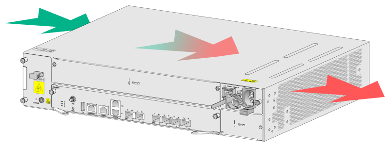
CAUTION: · Make sure a minimum clearance of 60 mm (2.36 in) is reserved around the inlet and outlet air vents. · Make sure the installation site has a good cooling system. |
To dissipate heat timely and ensure system stability, the device uses ventilation holes and pluggable fan trays. Consider the site ventilation design when you plan the installation site for the device.
Figure 9 Airflow direction
Acronyms
|
Full name |
|
|
1PPS |
1 Pulse Per Second |
|
AC |
Alternating Current |
|
BBU |
Baseband Unit |
|
DC |
Direct Current |
|
eCPRI |
enhanced Common Public Radio Interface |
|
FSW |
Front Haul Switch |
|
GNSS |
Global Navigation Satellite System |
|
MMF |
Multi-Mode Fiber |
|
NR |
New Radio Access |
|
pRRU |
Pico RRU |
|
RRU |
Remote Radio Unit |
|
SFP |
Small Form-factor Pluggable |
|
SMF |
Single Mode Fiber |
|
TOD |
Time of Day |
