- Table of Contents
-
- 12-Security Configuration Guide
- 00-Preface
- 01-DAE proxy configuration
- 02-Password control configuration
- 03-Keychain configuration
- 04-Public key management
- 05-PKI configuration
- 06-IPsec configuration
- 07-SSH configuration
- 08-SSL configuration
- 09-Session management
- 10-Object group configuration
- 11-Attack detection and prevention configuration
- 12-IP-based attack prevention configuration
- 13-IP source guard configuration
- 14-ARP attack protection configuration
- 15-ND attack defense configuration
- 16-uRPF configuration
- 17-SAVA configuration
- 18-SAVA-P configuration
- 19-Crypto engine configuration
- 20-Trust level configuration
- Related Documents
-
| Title | Size | Download |
|---|---|---|
| 18-SAVA-P configuration | 110.59 KB |
Specifying the router ID and IPv6 transport address
Specifying the SAVA-P interface type for an interface
Display and maintenance commands for SAVA-P
Example: Configuring SAVA-P basic network
Configuring SAVA-P
About SAVA
Source Address Validation Architecture Protocol (SAVA-P) is a protocol for preventing IPv6 source address spoofing attacks. A SAVA-P enabled device creates SAVA-P entries based on SAVA-P packets and packet incoming interfaces to verify the validity of IPv6 packet source prefixes. Upon receiving an IPv6 packet on an interface, the device searches for a SAVA-P entry with the prefix of the packet's source IPv6 address and the incoming interface. If no match is found, the device drops the packet.
SAVA-P can be deployed on all devices in the backbone network connecting to an access network.
SAVA-P packets
A device enabled with SAVA-P is called a SAVA-P device. Each SAVA-P device creates SAVA-P entries through the Source Prefix Advertisement (SPA) and Destination Prefix Probing (DPP) packets communicated between neighbor SAVA-P devices. A SAVA-P entry records the mapping between an IPv6 packet source prefix and a packet incoming interface.
SPA packets
When a SAVA-P device in an address domain learns a source prefix locally, the device will advertise the learned source prefix to its neighbors through SPA packets. In this way, each device can learn all source prefixes learned locally by other devices in the address domain. An SPA packet contains the following primary fields:
· Origin Router ID—Router ID of the SAVA-P device sending the SPA packet.
· Source Prefixes—Source prefixes coming from the direct routes learned locally or routes learned from the user–network interface (UNI).
DPP packets
A SAVA-P device sends an IPv6 DPP packet to probe the forwarding path of the packet with a specific destination address in the address domain. The devices along the path will create SAVA-P entries according to the DPP packet. A DPP packet contains the following primary fields:
· Origin Router ID—Router ID of the original SAVA-P device sending the DPP packet.
· Dest Prefixes—All destination prefixes in the local FIB table with the next hop as a specific SAVA-P neighbor of the device.
· Router ID List—List of router IDs for recording the path information of the DPP packet. When a SAVA-P neighbor of the device forwards the DPP packet to a next-hop neighbor, it will add its router ID to the router ID list.
SAVA-P operating mechanism
SAVA-P operates as follows:
1. Discovers SAVA-P neighbors and establishes TCP connections.
2. Generates and sends SPA packets.
3. Generates and sends DPP packets.
4. Creates SAVA-P entries.
5. Verifies received IPv6 packets based on the SAVA-P entries.
SAVA-P neighbor discovery and TCP establishment
If you configure the interface connecting two SAVA-P devices as a network-to-network interface (NNI), the two devices become SAVA-P neighbors. Configure the router ID and transport address on the devices. The devices establish a TCP connection as follows:
1. Each device sends a hello packet carrying its local transport address to the other device.
2. By comparing the local and peer transport address, the device with a lower transport address is selected as the TCP server, and the other device is selected as the TCP client.
3. The devices establish a TCP connection.
Generating and sending SPA packets
Each SAVA-P device in the address domain can generate an SPA packet based on the locally learned source prefixes and its router ID, and then sends the SPA packet to all its SAVA-P neighbors. When a SAVA-P neighbor receives the SPA packet, it takes different actions according to the router ID information.
· If the router ID in the received packet is the same as the locally configured router ID, the neighbor drops the packet.
· If the router ID in the received packet is different from the locally configured router ID, the neighbor saves the mapping between the source prefixes and the router ID in the packet to the local neighbor information table. Then the neighbor sends the SPA packet to all its SAVA-P neighbors.
In this way, each SAVA-P device can learn all the local source prefixes on other devices in the same address domain.
Generating and sending DPP packets
Each SAVA-P device in the address domain generates a DPP packet based on its router ID and all destination prefixes in the local FIB table with the next hop as a specific SAVA-P neighbor. The device then sends the DPP packets to the next-hop neighbors. When the SAVA-P neighbor receives a DPP packet, it takes different actions according to the router ID information.
· If the router ID in the received packet is the same as the locally configured router ID, the neighbor drops the packet.
· If the router ID in the received packet is different from the locally configured router ID, the neighbor matches the destination prefixes in the received packet with those in the local routing table.
¡ If a match is found, the neighbor adds its router ID to the router ID list in the DPP packet and then sends the packet to the next-hop neighbor corresponding to the matched destination prefix in the packet.
¡ If no match is found, the neighbor drops the packet.
Creating SAVA-P entries
After receiving a DPP packet, the SAVA-P device looks up locally stored source prefixes according to the origin router ID in the packet, and binds the packet source prefixes to the packet incoming interface to create SAVA-P entries. A SAVA-P entry records the mapping between an IPv6 packet source prefix and a packet incoming interface.
Verifying the received IPv6 packet based on the SAVA-P entries
SAVA-P entries can be used to verify the validity of received IPv6 packets. Upon receiving an IPv6 packet on an interface, the SAVA-P device searches for a SAVA-P entry with the prefix of the packet's source IPv6 address and the incoming interface. If no match is found, the device drops the packet.
SAVA-P tasks at a glance
To configure SAVA-P, perform the following tasks:
2. Specifying the router ID and IPv6 transport address
3. Specifying the SAVA-P interface type
4. (Optional.) Enabling SAVA-P logging
Enabling SAVA-P
1. Enter system view.
system-view
2. Enable SAVA-P.
By default, SAVA-P is disabled.
Specifying the router ID and IPv6 transport address
About this task
A router ID uniquely identifies the SAVA-P device sending the SPA or DPP packet that contains the source or destination prefixes.
Two SAVA-P devices connecting with each other are SAVA-P neighbors. Each SAVA-P device sends a hello packet carrying its local transport address to the other device. By comparing the local and peer transport addresses, the device with the lower transport address is selected as the TCP server, and the other device is selected as the TCP client. Then the devices establish a TCP connection.
Restrictions and guidelines
As a best practice, specify the router ID as the IPv4 address of a loopback interface on a SAVA-P device. Reachability is not required for the IP address.
As a best practice, specify the transport address as the IPv6 address of a loopback interface on a SAVA-P device. For successful TCP establishment, make sure the IP address is reachable.
Procedure
1. Enter system view.
system-view
2. Specify the router ID and IPv6 transport address for the SAVA-P device.
ipv6 sava protocol id router-id transport-address ipv6-address
By default, the router ID and IPv6 transport address are not specified for a SAVA-P device.
Specifying the SAVA-P interface type for an interface
About this task
SAVA-P devices support configuring the following types of interfaces:
· NNI—Used for connecting SAVA-P neighbors. If you configure the interfaces connecting two SAVA-P devices as a NNI, the devices become SAVA-P neighbors.
· UNI—Used for connecting the user network.
A SAVA-P device generates a user-side prefix entry based on the indirect route reaching the user access network learned from the UNI. The device sends the prefix to the SAVA-P neighbor through the NNI. The SAVA-P neighbor creates a SAVA-P entry based on the prefix and the packet incoming interface.
Restrictions and guidelines
If you specify the SAVA-P interface type as NNI for an interface, do not enable SAVA on the interface. For more information about SAVA, see "Configuring SAVA."
Procedure
1. Enter system view.
system-view
2. Specify the SAVA-P interface type for an interface.
ipv6 sava protocol port-type { nni | uni }
By default, the SAVA-P interface type is not specified for the interface.
Enabling SAVA-P logging
About this task
To identify and troubleshoot issues, enable SAVA-P logging.
This feature enables the device to generate log messages when spoofing packets are detected by SAVA-P. The log messages are sent to the information center and output according to the configured log destinations and output rules. For more information about the information center, see Network Management and Monitoring Configuration Guide.
Procedure
1. Enter system view.
system-view
2. Enable SAVA-P logging.
ipv6 sava protocol log enable spoofing-packet [ interval interval | number number ] *
By default, SAVA-P logging is disabled.
Display and maintenance commands for SAVA-P
Execute the display commands in any view.
|
Task |
Command |
|
Display SAVA-P entries. |
display ipv6 sava protocol entry [ interface interface-type interface-number | vpn-instance vpn-instance-name | slot slot-number ] |
|
Display SAVA-P packet drop statistics. |
display ipv6 sava protocol packet-drop statistics [ interface interface-type interface-number ] |
|
Clear SAVA-P packet drop statistics. |
reset ipv6 sava protocol packet-drop statistics [ interface interface-type interface-number ] |
SAVA-P configuration examples
Example: Configuring SAVA-P basic network
Network configuration
As shown in Figure 1, valid users in the LAN use prefix 10::/64. Configure SAVA-P on Device A and Device B to meet the following requirements:
· Device A and Device B establish SAVA-P neighbor relationship and create SAVA-P entries through the SPA and DPP packets communicated between them.
· Device A and Device B perform source address validity check and filter packets from the user network based on SAVA-P entries.
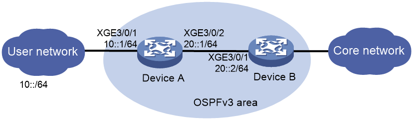
Prerequisites
1. Assign IPv6 addresses to interfaces on the devices.
2. Configure OSPFv3 on the backbone network. For more information, see OSPFv3 configuration in Layer 3—IP Routing Configuration Guide.
Procedure
1. Configure Device A:
# Enable SAVA-P.
<DeviceA> system-view
[DeviceA] ipv6 sava protocol enable
# Specify the router ID and IPv6 transport address.
[DeviceA] ipv6 sava protocol id 1.1.1.1 transport-address 1::9
# Specify interface Ten-GigabitEthernet3/0/1 as a UNI and specify interface Ten-GigabitEthernet3/0/2 as a NNI.
[DeviceA] interface ten-gigabitethernet 3/0/1
[DeviceA-Ten-GigabitEthernet3/0/1] ipv6 sava protocol port-type uni
[DeviceA-Ten-GigabitEthernet3/0/1] quit
[DeviceA] interface ten-gigabitethernet 3/0/2
[DeviceA-Ten-GigabitEthernet3/0/2] ipv6 sava protocol port-type nni
[DeviceA-Ten-GigabitEthernet3/0/2] quit
2. Configure Device B:
# Enable SAVA-P.
<DeviceB> system-view
[DeviceB] ipv6 sava protocol enable
# Specify the router ID and IPv6 transport address.
[DeviceB] ipv6 sava protocol id 2.2.2.2 transport-address 2::9
# Specify the SAVA-P interface type.
[DeviceB] interface ten-gigabitethernet 3/0/1
[DeviceB-Ten-GigabitEthernet3/0/1] ipv6 sava protocol port-type nni
Verifying the configuration
# Display SAVA-P entries on Device B.
<DeviceB> display ipv6 sava protocol entry
IPv6 SAVA protocol entry count: 4
Destination/Prefix length Interface VPN instance
10::/64 XGE3/0/1 --
10::1/128 XGE3/0/1 --
20::/64 XGE3/0/1 --
20::1/128 XGE3/0/1 --
The output shows that Device B learned the SAVA-P entry corresponding to the source prefix of Device A. When Device B receives a user-side packet from Device A, it can perform packet source address validity check based on the SAVA-P entry.