- Table of Contents
-
- 12-Security Configuration Guide
- 00-Preface
- 01-DAE proxy configuration
- 02-Password control configuration
- 03-Keychain configuration
- 04-Public key management
- 05-PKI configuration
- 06-IPsec configuration
- 07-SSH configuration
- 08-SSL configuration
- 09-Session management
- 10-Object group configuration
- 11-Attack detection and prevention configuration
- 12-IP-based attack prevention configuration
- 13-IP source guard configuration
- 14-ARP attack protection configuration
- 15-ND attack defense configuration
- 16-uRPF configuration
- 17-SAVA configuration
- 18-SAVA-P configuration
- 19-Crypto engine configuration
- 20-Trust level configuration
- Related Documents
-
| Title | Size | Download |
|---|---|---|
| 20-Trust level configuration | 280.79 KB |
Restrictions and guidelines: Trust level configuration
Prerequisites for trust level configuration
Configuring a trust level server
Restrictions and guidelines for configuring a trust level server
Trust level server configuration tasks at a glance
Enabling the trust level server feature
Configuring a trust level policy
Configuring parameters for secure transmission of packets
Enabling the trust level feature on an interface
Configuring a trust level client
Restrictions and guidelines for configuring a trust level client
Configuring parameters of a trust level server
Enabling the trust level feature on an interface
Trust level configuration examples
Example: Configuring trust levels
Configuring trust levels
About trust levels
Trust level is a network technology used to realize secure forwarding of IPv6 packets. From the perspective of security and trustworthiness, you can determine the security levels for users with different security requirements, and determine the trustworthiness levels of the network transmission devices according to their performance and reliability. The trust level technology provides different forwarding paths for packets with different security levels, so as to achieve trusted forwarding.
Trust network architecture
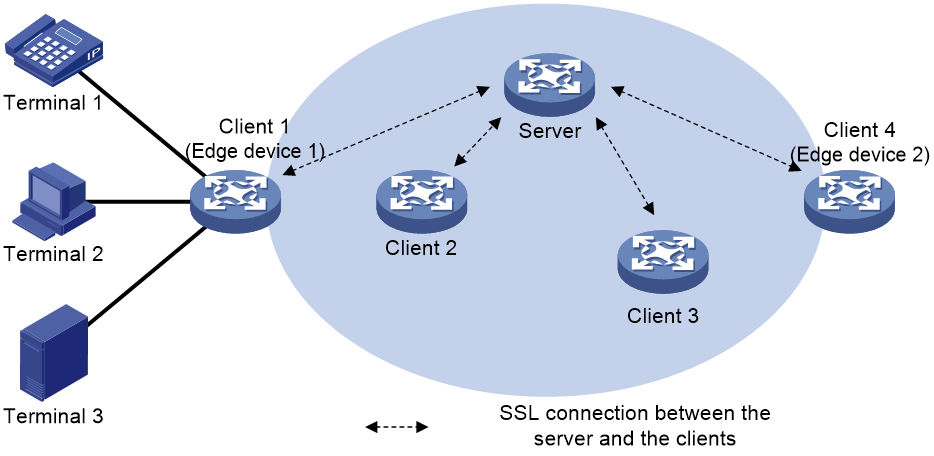
As shown in Figure 1, a trusted network adopts the Client/Server mode, in which the trust level feature is enabled on each network transmission device. The devices in the trust network architecture include terminals and network transmission devices.
Figure 1 Trust network architecture
Terminal
A terminal in a trust network (terminal) refers to a device with a security level in its IP address and secure communication requirements. In the IP address of a terminal, three bits are used to carry the security levels of the packets generated by the terminal, so as to identify the trustworthiness of the packets.
Network transmission device
Network transmission devices include the following types according to the device location in the transmission network:
· Edge device—Network transmission devices located at the edge of a trust network and connected to Layer 3 of the terminals. The security levels of the packets received by edge devices are extracted according to the configuration.
· Non-edge device—Network transmission devices that participate in trusted forwarding except edge devices. The packets received by non-edge devices can be forwarded normally according to the routes, without extracting their security levels.
Network transmission devices include the following types according to the device function in the transmission network:
· Server—Network transmission devices acting as the server in a trust network. The server is the configuration center of the trust network. You need to configure the trust level policies and the parameters for secure transmission of packets on the server. The server deploys the configurations related to the trust level policies and the parameters for secure transmission of packets to all clients through SSL connection.
The server can be deployed as an edge device or a non-edge device. A device can only act as a server or a client.
Multiple servers can be deployed in a trust network, and a client can only be connected to a server. Make sure the configurations of trust level modules on multiple servers in a trust network are consistent. Otherwise, the packets cannot be forwarded according to the expected paths.
· Client—Network transmission devices acting as the clients in a trust network. According to the configurations deployed by the server, a client calculates the trusted forwarding path and completes trusted forwarding of packets.
Basic concepts
Security level
Security level is an attribute carried in the packets generated by the terminal to identify the trustworthiness of the packets. The network transmission devices securely forward the packets according to the security levels of the packets.
Packets are classified into eight security levels from 0 through 7 in ascending order. The larger the value, the higher the security level and the trustworthiness.
Trust level
Trust level is an attribute of the network transmission devices in a trust network to identify device trustworthiness. Network transmission devices are classified into eight trust levels from 0 through 7 in ascending order, corresponding to eight packet security levels. The larger the value, the higher the security level and the trustworthiness.
A network transmission device forwards packets with a security level that is lower than or equal to its trust level. For example, a network transmission device with a trust level of 5 forwards packets with security levels of 0 to 5, but not packets with security levels of 6 and 7.
Boundary point
Boundary point is a parameter configured on the server to extract the security level of packets. The boundary point configurations are deployed to all clients. This command only takes effect on edge devices.
You need to configure eight boundary points (boundary point 0 to boundary point 7) on the server to extract eight security levels of the packets respectively. The boundary points use IPv6 address format. The generation method of the boundary points is shown in Figure 2.
Figure 2 Generation method of the boundary points
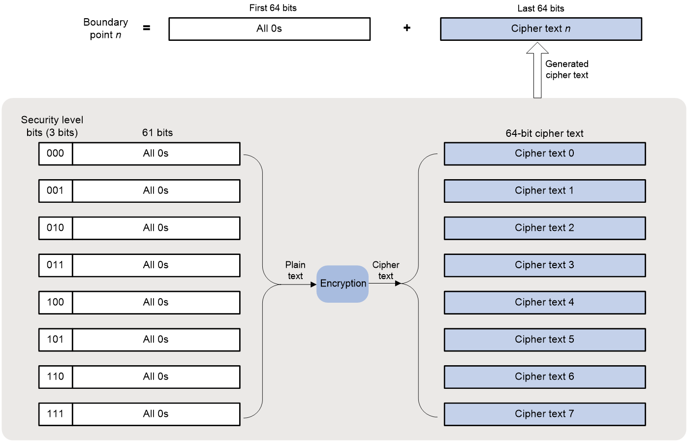
For example, boundary point 1 is generated as follows:
1. Take the 64-bit binary number (with three security level bits of 001 and 61 bits of 0) as the plain text.
2. Use the same algorithm as that used by the terminal to encrypt the plain text to generate a 64-bit cipher text.
3. The 64-bit number with all bits of 0 and the generated 64-bit cipher text together form boundary point 1.
Edge devices use the boundary points to extract the packet security levels according to the following rules:
· If the last 64 bits of the source IPv6 addresses of the received packets are in the range of cipher text 0 to cipher text 1, the security level of the packets is 0.
· If the last 64 bits of the source IPv6 addresses of the received packets are in the range of cipher text 1 to cipher text 2, the security level of the packets is 1.
· By analogy, if the last 64 bits of the source IPv6 addresses of the received packets are in the range of cipher text 7 to cipher text 0, the security level of the packets is 7.
Trust level policy
A trust level policy is used to specify a network transmission device and its trust level. You need to configure a trust level policy on the server for each network transmission device participating in trusted forwarding (all servers and clients).
Trust levels and IS-IS protocol cooperate to generate trusted forwarding topologies. In a trust level policy, an IS-IS System ID uniquely identifies a network transmission device. For more information about IS-IS System ID, see IS-IS configuration in Layer 3—IP Routing Configuration Guide.
Flex-Algo
Flexible algorithm (Flex-Algo) is an algorithm used by IS-IS to calculate routing topologies. IS-IS traditionally calculates optimal paths based on the IGP metric values of all links. This might not meet the traffic requirements. Flexible algorithm allows users to control path selection flexibly by customizing path calculation methods. For more information about flexible algorithm, see IS-IS configuration in Layer 3—IP Routing Configuration Guide.
IS-IS protocol can use flexible algorithms to generate routing topologies of network transmission devices that meet the specified trust level requirements.
In trust level technology, flexible algorithm is a parameter bound to a packet security level. Flexible algorithms and the packet security levels together control the packets with specified security levels to be forwarded through the corresponding routing topologies.
Service class
Service class is the basis for an SRv6 TE policy to select the forwarding tunnels. SRv6 TE policy Class Based Tunnel Selection (CBTS) enables dynamic routing and forwarding of traffic with service class values over different SRv6 TE policy tunnels between the same tunnel headend and tailed. CBTS uses a dedicated tunnel for a certain class of service to implement differentiated forwarding for services.
In trust level technology, service class is a parameter for secure transmission of packets. A service class associates an SRv6 TE policy with a packet security level. Then the packets with the specified security level can be forwarded through a matching SRv6 tunnel.
Trusted forwarding mechanism
Trusted forwarding overview
The mechanism of trusted forwarding includes the following operations:
1. Planning the network and configuring the trust level feature
2. Generating network topologies based on flexible algorithms
3. Generating trusted packets on the terminals
4. Extracting the security levels of packets received by edge devices
5. Packet forwarding based on service classes
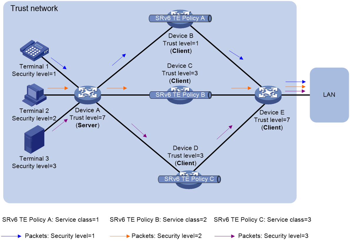
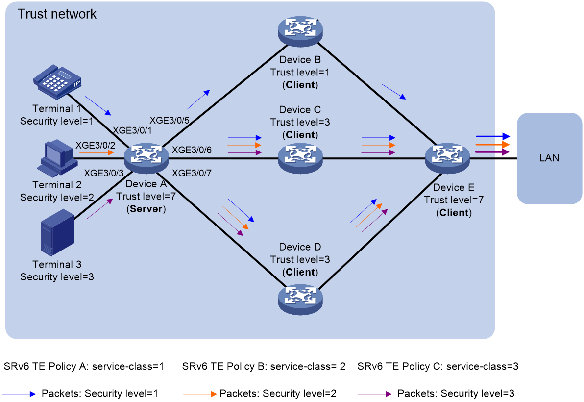
Figure 3 shows a packet forwarding process in a trust network.
Figure 3 Trust network forwarding diagram
Planning the network and configuring the trust level feature
Before trusted forwarding, you need to plan the network. The components to be planned includes the security levels of the terminals, the network transmission devices participating in trusted forwarding and their trust levels, the forwarding paths of packets with different security levels, the server and clients in the trust network.
For the trust network in Figure 3, the network is planned as shown in Table 1 and Table 2.
Table 1 Planning of packet security levels, flexible algorithms, and service classes
|
Terminal |
Packet security level |
Flexible algorithm identifier |
Service class |
|
Terminal 1 |
1 |
201 |
1 |
|
Terminal 2 |
2 |
202 |
2 |
|
Terminal 3 |
3 |
203 |
3 |
Table 2 Planning of device trust level policies, IS-IS System IDs, and trust levels
|
Trust level policy name |
IS-IS System ID |
Trust level |
|
forDeviceA |
1680.1000.1001 |
7 |
|
forDeviceB |
1680.1000.1002 |
1 |
|
forDeviceC |
1680.1000.1003 |
3 |
|
forDeviceD |
1680.1000.1004 |
3 |
|
forDeviceE |
1680.1000.1005 |
7 |
After network planning, the following steps are taken to realize trusted forwarding:
1. The configurations of these parameters are completed on the server.
2. SSL connection between the server and the clients is established.
3. The server deploys the parameters to all clients.
4. The server and all clients use these parameters to perform trusted forwarding of packets.
Generating network topologies based on flexible algorithms
1. A network transmission device deploys the flexible algorithms supported by the device to neighboring devices according to its trust level. If the security levels of the received packets are lower than or equal to the trust level of the device, the flexible algorithms are deployed.
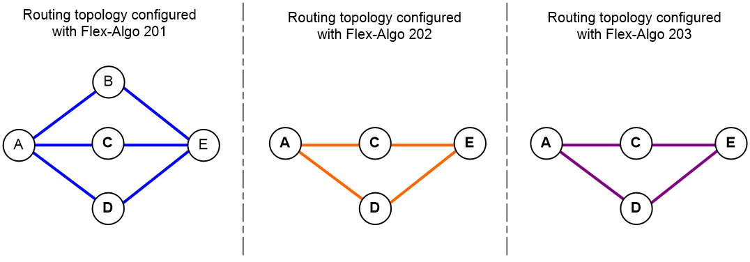
2. For the trust network in Figure 3, IS-IS protocol calculates the routing topologies according to IS-IS System IDs and flexible algorithms, as shown in Figure 4.
¡ The trust level of Device A and Device E is 7, and flexible algorithm 201, 202, and 203 are deployed.
¡ The trust level of Device B is 1, and flexible algorithm 201 is deployed.
¡ The trust level of Device C and Device D is 3, and flexible algorithm 201, 202, and 203 are deployed.
Figure 4 Calculated routing topologies
Generating trusted packets on the terminals
When a terminal generates packets, it selects three bits from the last 64 bits of the source IPv6 addresses to identify the security levels of the packets. The terminal sends the source IPv6 addresses to the edge device (Device A) after algorithm conversion.
For the trust network in Figure 3:
The security level of the packets generated by Terminal 1 is 1.
The security level of the packets generated by Terminal 2 is 2.
The security level of the packets generated by Terminal 3 is 3.
Extracting the security levels of packets received by edge devices
After receiving the packets sent by the terminals, the edge device (Device A) extracts the security levels of the packets according to the boundary point configuration. Then it binds the flexible algorithms and service classes to the security levels according to the configuration in Table 1.
· For packets with security level 1, the corresponding flexible algorithm is 201, the service class is 1, and the routing topology configured with flexible algorithm 201 is used.
· For packets with security level 2, the corresponding flexible algorithm is 202, the service class is 2, and the routing topology configured with flexible algorithm 202 is used.
· For packets with security level 3, the corresponding flexible algorithm is 203, the service class is 3, and the routing topology configured with flexible algorithm 203 is used.
Packet forwarding based on service classes
The edge device (Device A) finds the matching SRv6 TE policy tunnel according to the packet security levels and service classes. The candidate path of an SRv6 TE policy is calculated in the corresponding routing topology configured with specific flexible algorithm. If multiple physical paths exist in the routing topology, with an SRv6 TE policy, the traffic can be load shared among multiple paths, or a path can be strictly selected in priority to send the packets to the next network transmission device.
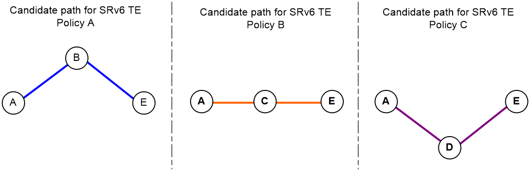
For the routing topologies in Figure 4, when strictly selecting a physical path, the SRv6 TE policy selects a forwarding path as follows:
· The service class of the packets with security level 1 is 1, matching with SRv6 TE Policy A. The candidate path Device A > Device B > Device E for SRv6 TE Policy A is calculated in the routing topology configured with flexible algorithm 201.
· The service class of the packets with security level 2 is 2, matching with SRv6 TE Policy B. The candidate path Device A > Device C > Device E for SRv6 TE Policy B is calculated in the routing topology configured with flexible algorithm 202.
· The service class of the packets with security level 3 is 3, matching with SRv6 TE Policy C. The candidate path Device A > Device D > Device E for SRv6 TE Policy C is calculated in the routing topology configured with flexible algorithm 203.
The actual forwarding paths of the packets are finally calculated as shown in Figure 5.
Figure 5 Strictly calculated actual forwarding topologies
For non-edge devices (Device B, Device C, Device D, and Device E), the received packets can be forwarded normally through SRv6 tunnels.
Restrictions and guidelines: Trust level configuration
If the trust level feature is disabled, all trust level configurations of the device are automatically restored to the default. Use it with caution.
Prerequisites for trust level configuration
Before configuring the trust levels, you must complete the following tasks on the server and the clients:
· Configure SSL:
¡ Configure an SSL server policy when the device acts as an SSL server.
¡ Configure an SSL client policy when the device acts as an SSL client.
If an SSL policy is empty or misconfigured, the connection between the trust level server and clients fails. For more information about SSL, see "Configuring SSL."
· Configure IS-IS.
Configure basic IS-IS, IS-IS System IDs, IS-IS flexible algorithms, and so on. For more information about flexible algorithm, see IS-IS configuration in Layer 3—IP Routing Configuration Guide.
The flexible algorithms configured for IS-IS protocol must contain flexible algorithms needed in the trust level feature.
Configuring a trust level server
Restrictions and guidelines for configuring a trust level server
In a trust network, a device can only act as a server or a client. A device needs to exit the client mode so as to be used as a server.
When exiting the server mode, all configurations of the device in the server mode are automatically restored to the default. Use it with caution.
Trust level server configuration tasks at a glance
To configure a trust level server, perform the following tasks:
1. Enabling the trust level server feature
2. Configuring a trust level policy
3. Configuring parameters for secure transmission of packets
4. Enabling the trust level feature on an interface
This task is required when a server is deployed on an edge device.
Enabling the trust level server feature
1. Enter system view.
system-view
2. Enter trust-level view and enable the trust level feature.
trust-level
By default, the trust level feature is disabled.
3. Enable the trust level server feature and enter trust-level-server view.
server enable
By default, the trust level server feature is disabled.
4. Bind an SSL policy for the server.
bind ssl-server-policy ssl-server-policy-name
By default, no SSL policies for the server are bound.
Configuring a trust level policy
1. Enter system view.
system-view
2. Enter trust-level view.
trust-level
3. Create a trust level policy and enter trust-level-policy view.
policy policy-name
You can create multiple trust level policies. You need to configure trust level policies for each network transmission device participating in trusted forwarding.
4. Configure an IS-IS System ID contained in the trust level policy.
isis-system-id system-id
By default, the IS-IS System ID matching with the trust level policy is not configured.
If you execute this command multiple times, the most recent configuration takes effect.
5. Configure the trust level of the device.
trust level trust-level
By default, the trust level of the device is not configured.
If you execute this command multiple times, the most recent configuration takes effect.
Configuring parameters for secure transmission of packets
1. Enter system view.
system-view
2. Enable the trust level feature and enter trust-level view.
trust-level
By default, the trust level feature is disabled.
3. Configure the boundary points for extracting the packet security levels.
boundary origin-point k0 level-point k1 k2 k3 k4 k5 k6 k7
By default, no boundary points for extracting the packet security levels are configured.
4. Enter packet security level view.
security-level sec-level
For the security-level command to take effect, you must first use the server enable command to enable the trust level server feature.
5. Bind a flexible algorithm to a security level.
flex-algo algorithm-id
By default, no flexible algorithm is bound to a security level.
6. Bind a service class for an SRv6 TE policy to a security level.
service-class service-class-value
By default, no service class for an SRv6 TE policy is bound to a security level.
Enabling the trust level feature on an interface
About this task
When a server is deployed on an edge device, enable the trust level feature on the interfaces of the edge device connected to the terminals.
With the trust level feature on the interfaces enabled, the edge device can extract the security levels of the received packets according to the boundary point configuration for trusted forwarding.
Do not configure this feature on non-edge devices. The packets received by non-edge devices can be forwarded normally according to the routes.
Restrictions and guidelines
This feature can only be configured on a Layer 3 Ethernet interface or subinterface, or Layer 3 aggregate interface or subinterface.
To successfully configure this feature on a Layer 3 Ethernet or aggregate subinterface, make sure common Dot1q termination or common QinQ termination is enabled on the subinterface (by using the vlan-type dot1q vid or vlan-type dot1q vid second-dot1q command). For more information about VLAN termination commands, see Layer 2—LAN Switching Command Reference.
Procedure
1. Enter system view.
system-view
2. Enter interface view.
interface interface-type interface-number
3. Enable the trust level feature on an interface.
port trust-level enable
By default, the trust level feature on an interface is disabled.
Configuring a trust level client
Restrictions and guidelines for configuring a trust level client
In a trust network, a device can only act as a server or a client. A device needs to exit the server mode so as to be used as a client.
When exiting the client mode, all configurations of the device in the client mode are automatically restored to the default. Use it with caution.
Configuring parameters of a trust level server
1. Enter system view.
system-view
2. Enable the trust level feature and enter trust-level view.
trust-level
By default, the trust level feature is disabled.
3. Enable the trust level client feature and enter trust-level-client view.
client enable
By default, the trust level client feature is disabled.
4. Configure parameters of a trust level server.
server ipv6-address ipv6-address ssl-client-policy policy-name
By default, no parameters of a trust level server are configured.
Enabling the trust level feature on an interface
About this task
When a server is deployed on an edge device, enable the trust level feature on the interfaces of the edge device connected to the terminals.
With the trust level feature on the interfaces enabled, the edge device can extract the security levels of the received packets according to the boundary point configuration for trusted forwarding.
Do not configure this feature on non-edge devices. The packets received by non-edge devices can be forwarded normally according to the routes.
Restrictions and guidelines
This feature can only be configured on a Layer 3 Ethernet interface or subinterface, or Layer 3 aggregate interface or subinterface.
To successfully configure this feature on a Layer 3 Ethernet or aggregate subinterface, make sure common Dot1q termination or common QinQ termination is enabled on the subinterface (by using the vlan-type dot1q vid or vlan-type dot1q vid second-dot1q command). For more information about VLAN termination commands, see Layer 2—LAN Switching Command Reference.
Procedure
1. Enter system view.
system-view
2. Enter interface view.
interface interface-type interface-number
3. Enable the trust level feature on an interface.
port trust-level enable
By default, the trust level feature on an interface is disabled.
Trust level configuration examples
Example: Configuring trust levels
Network configuration
Three terminals are deployed in a trust network: IP phone (with security level 1), host (with security level 2), and DHCP server (with security level 3).
Device A and Device E are the most trusted, with trust level 7. The trust level of Device B is the lowest, which is 1. The trust level of Device C and Device D is medium, which is 3.
According to the security level of the terminals, trusted forwarding of the packets generated by the terminals is as follows:
· The packets generated by the IP phone are forwarded in three paths: Device A > Device B > Device E, Device A > Device C > Device E, and Device A > Device D > Device E.
· The packets generated by the host are forwarded in two paths: Device A > Device C > Device E and Device A > Device D > Device E.
· The packets generated by the DHCP server are forwarded in two paths: Device A > Device C > Device E and Device A > Device D > Device E.
Figure 6 Trust level configuration network diagram
Prerequisites
1. Plan the parameters needed for trusted forwarding, as shown in Table 3 and Table 4.
Table 3 Planning of IS-IS System IDs
|
Network transmission device |
Trust level |
IS-IS System ID |
SRv6 locator |
|
DeviceA |
7 |
0000.0000.0001 |
AA:xx::/64 (xx is a flexible algorithm identifier) |
|
DeviceB |
1 |
0000.0000.0002 |
BB:xx::/64 (xx is a flexible algorithm identifier) |
|
DeviceC |
3 |
0000.0000.0003 |
CC:xx::/64 (xx is a flexible algorithm identifier) |
|
DeviceD |
3 |
0000.0000.0004 |
DD:xx::/64 (xx is a flexible algorithm identifier) |
|
DeviceE |
7 |
0000.0000.0005 |
EE:xx::/64 (xx is a flexible algorithm identifier) |
Table 4 Planning of packet security levels, service classes, and flexible algorithms
|
Security level |
Service class value |
Flexible algorithm identifier |
|
0 |
0 |
130 |
|
1 |
1 |
131 |
|
2 |
2 |
132 |
|
3 |
3 |
133 |
|
4 |
4 |
134 |
|
5 |
5 |
135 |
|
6 |
6 |
136 |
|
7 |
7 |
137 |
2. Configure SSL:
a. Configure Device A as the SSL server.
b. Configure Device B, Device C, Device D, and Device E as the SSL clients.
c. Establish SSL connection between the SSL server and the SSL clients.
For more information about SSL, see "Configuring SSL."
3. Configure basic IS-IS.
Configure basic IS-IS on Device A, Device B, Device C, Device D, and Device E to make sure IS-IS packets can communicate with each other. For more information about IS-IS, see Layer 3—IP Routing Configuration Guide.
4. Configure boundary points.
According to the generation rules of boundary points, generate eight boundary points: boundary point 0 to boundary point 7. The eight boundary points in this example are ::8000:0:0:0, ::2000:0:0:0, ::4000:0:0:0, ::6000:0:0:0, ::, ::A000:0:0:0, ::C000:0:0:0, ::E000:0:0:0.
Procedure
1. Configure Device A (trust level server):
a. Configure trust levels.
# Configure trust level policy a, b, c, d, and e for Device A, Device B, Device C, Device D, and Device E.
<DeviceA> system-view
[DeviceA] trust-level
[DeviceA-trust-level] server enable
[DeviceA-trust-level-server] quit
[DeviceA-trust-level] policy a
[DeviceA-trust-level-policy-a] isis-system-id 0000.0000.0001
[DeviceA-trust-level-policy-a] trust level 7
[DeviceA-trust-level-policy-a] policy b
[DeviceA-trust-level-policy-b] isis-system-id 0000.0000.0002
[DeviceA-trust-level-policy-b] trust level 1
[DeviceA-trust-level-policy-b] policy c
[DeviceA-trust-level-policy-c] isis-system-id 0000.0000.0003
[DeviceA-trust-level-policy-c] trust level 3
[DeviceA-trust-level-policy-c] policy d
[DeviceA-trust-level-policy-d] isis-system-id 0000.0000.0004
[DeviceA-trust-level-policy-d] trust level 3
[DeviceA-trust-level-policy-d] policy e
[DeviceA-trust-level-policy-e] isis-system-id 0000.0000.0005
[DeviceA-trust-level-policy-e] trust level 7
[DeviceA-trust-level-policy-e] quit
# Configure the boundary points for extracting the security levels of packets.
[DeviceA-trust-level] boundary origin-point ::8000:0:0:0 level-point ::2000:0:0:0 ::4000:0:0:0 ::6000:0:0:0 :: ::A000:0:0:0 ::C000:0:0:0 ::E000:0:0:0
# Configure the flexible algorithms and the service classes for security level 0 to 7.
[DeviceA-trust-level] security-level 0
[DeviceA-trust-level-sec-0] service-class 0
[DeviceA-trust-level-sec-0] flex-algo 130
[DeviceA-trust-level-sec-0] security-level 1
[DeviceA-trust-level-sec-1] service-class 1
[DeviceA-trust-level-sec-1] flex-algo 131
[DeviceA-trust-level-sec-1] security-level 2
[DeviceA-trust-level-sec-2] service-class 2
[DeviceA-trust-level-sec-2] flex-algo 132
[DeviceA-trust-level-sec-2] security-level 3
[DeviceA-trust-level-sec-3] service-class 3
[DeviceA-trust-level-sec-3] flex-algo 133
[DeviceA-trust-level-sec-3] security-level 4
[DeviceA-trust-level-sec-4] service-class 4
[DeviceA-trust-level-sec-4] flex-algo 134
[DeviceA-trust-level-sec-4] security-level 5
[DeviceA-trust-level-sec-5] service-class 5
[DeviceA-trust-level-sec-5] flex-algo 135
[DeviceA-trust-level-sec-5] security-level 6
[DeviceA-trust-level-sec-6] service-class 6
[DeviceA-trust-level-sec-6] flex-algo 136
[DeviceA-trust-level-sec-6] security-level 7
[DeviceA-trust-level-sec-7] service-class 7
[DeviceA-trust-level-sec-7] flex-algo 137
[DeviceA-trust-level-sec-7] quit
[DeviceA-trust-level] quit
# Enable the trust level feature on Ten-GigabitEthernet3/0/1, Ten-GigabitEthernet3/0/2, and Ten-GigabitEthernet3/0/3 of Device A.
[DeviceA] interface ten-gigabitethernet 3/0/1
[DeviceA-Ten-GigabitEthernet3/0/1] port trust-level enable
[DeviceA-Ten-GigabitEthernet3/0/1] quit
[DeviceA] interface ten-gigabitethernet 3/0/2
[DeviceA-Ten-GigabitEthernet3/0/2] port trust-level enable
[DeviceA-Ten-GigabitEthernet3/0/2] quit
[DeviceA] interface ten-gigabitethernet 3/0/3
[DeviceA-Ten-GigabitEthernet3/0/3] port trust-level enable
[DeviceA-Ten-GigabitEthernet3/0/3] quit
b. Configure IS-IS.
# Configure an IS-IS System ID and enable IPv6 IS-IS.
[DeviceA] isis 1
[DeviceA-isis-1] network-entity 00.0000.0000.0001.00
[DeviceA-isis-1] cost-style wide
[DeviceA-isis-1] address-family ipv6 unicast
[DeviceA-isis-1-ipv6] quit
[DeviceA-isis-1] quit
[DeviceA] interface ten-gigabitethernet 3/0/5
[DeviceA-Ten-GigabitEthernet3/0/5] isis ipv6 enable 1
[DeviceA-Ten-GigabitEthernet3/0/5] quit
[DeviceA] interface ten-gigabitethernet 3/0/6
[DeviceA-Ten-GigabitEthernet3/0/6] isis ipv6 enable 1
[DeviceA-Ten-GigabitEthernet3/0/6] quit
[DeviceA] interface ten-gigabitethernet 3/0/7
[DeviceA-Ten-GigabitEthernet3/0/7] isis ipv6 enable 1
[DeviceA-Ten-GigabitEthernet3/0/7] quit
[DeviceA] interface loopback 0
[DeviceA-LoopBack0] isis ipv6 enable 1
[DeviceA-LoopBack0] quit
# Configure flexible algorithm 130 to 137 matching with the trust levels.
[DeviceA] isis 1
[DeviceA-isis-1] flex-algo 130
[DeviceA-isis-1-flex-algo-130] trust-level-mapping enable
[DeviceA-isis-1-flex-algo-130] advertise-definition enable
[DeviceA-isis-1-flex-algo-130] quit
[DeviceA-isis-1] flex-algo 131
[DeviceA-isis-1-flex-algo-131] trust-level-mapping enable
[DeviceA-isis-1-flex-algo-131] advertise-definition enable
[DeviceA-isis-1-flex-algo-131] quit
[DeviceA-isis-1] flex-algo 132
[DeviceA-isis-1-flex-algo-132] trust-level-mapping enable
[DeviceA-isis-1-flex-algo-132] advertise-definition enable
[DeviceA-isis-1-flex-algo-132] quit
[DeviceA-isis-1] flex-algo 133
[DeviceA-isis-1-flex-algo-133] trust-level-mapping enable
[DeviceA-isis-1-flex-algo-133] advertise-definition enable
[DeviceA-isis-1-flex-algo-133] quit
[DeviceA-isis-1] flex-algo 134
[DeviceA-isis-1-flex-algo-134] trust-level-mapping enable
[DeviceA-isis-1-flex-algo-134] advertise-definition enable
[DeviceA-isis-1-flex-algo-134] quit
[DeviceA-isis-1] flex-algo 135
[DeviceA-isis-1-flex-algo-135] trust-level-mapping enable
[DeviceA-isis-1-flex-algo-135] advertise-definition enable
[DeviceA-isis-1-flex-algo-135] quit
[DeviceA-isis-1] flex-algo 136
[DeviceA-isis-1-flex-algo-136] trust-level-mapping enable
[DeviceA-isis-1-flex-algo-136] advertise-definition enable
[DeviceA-isis-1-flex-algo-136] quit
[DeviceA-isis-1] flex-algo 137
[DeviceA-isis-1-flex-algo-137] trust-level-mapping enable
[DeviceA-isis-1-flex-algo-137] advertise-definition enable
[DeviceA-isis-1-flex-algo-137] quit
[DeviceA-isis-1] quit
c. Configure an SRv6 SID.
# Configure a locator for public topology.
[DeviceA] segment-routing ipv6
[DeviceA-segment-routing-ipv6] locator a0 ipv6-prefix AA:: 64 static 8
[DeviceA-segment-routing-ipv6-locator-a] quit
# Configure the locators associated with flexible algorithm 130 to 137.
[DeviceA-segment-routing-ipv6] locator a130 ipv6-prefix AA:130:: 64 static 8
[DeviceA-segment-routing-ipv6-locator-a130] flex-algo algorithm 130
[DeviceA-segment-routing-ipv6-locator-a130] opcode 1 end no-flavor
[DeviceA-segment-routing-ipv6-locator-a130] quit
[DeviceA-segment-routing-ipv6] locator a131 ipv6-prefix AA:131:: 64 static 8
[DeviceA-segment-routing-ipv6-locator-a131] flex-algo algorithm 131
[DeviceA-segment-routing-ipv6-locator-a131] opcode 1 end no-flavor
[DeviceA-segment-routing-ipv6-locator-a131] quit
[DeviceA-segment-routing-ipv6] locator a132 ipv6-prefix AA:132:: 64 static 8
[DeviceA-segment-routing-ipv6-locator-a132] flex-algo algorithm 132
[DeviceA-segment-routing-ipv6-locator-a132] opcode 1 end no-flavor
[DeviceA-segment-routing-ipv6-locator-a132] quit
[DeviceA-segment-routing-ipv6] locator a133 ipv6-prefix AA:133:: 64 static 8
[DeviceA-segment-routing-ipv6-locator-a133] flex-algo algorithm 133
[DeviceA-segment-routing-ipv6-locator-a133] opcode 1 end no-flavor
[DeviceA-segment-routing-ipv6-locator-a133] quit
[DeviceA-segment-routing-ipv6] locator a134 ipv6-prefix AA:134:: 64 static 8
[DeviceA-segment-routing-ipv6-locator-a134] flex-algo algorithm 134
[DeviceA-segment-routing-ipv6-locator-a134] opcode 1 end no-flavor
[DeviceA-segment-routing-ipv6-locator-a134] quit
[DeviceA-segment-routing-ipv6] locator a135 ipv6-prefix AA:135:: 64 static 8
[DeviceA-segment-routing-ipv6-locator-a135] flex-algo algorithm 135
[DeviceA-segment-routing-ipv6-locator-a135] opcode 1 end no-flavor
[DeviceA-segment-routing-ipv6-locator-a135] quit
[DeviceA-segment-routing-ipv6] locator a136 ipv6-prefix AA:136:: 64 static 8
[DeviceA-segment-routing-ipv6-locator-a136] flex-algo algorithm 136
[DeviceA-segment-routing-ipv6-locator-a136] opcode 1 end no-flavor
[DeviceA-segment-routing-ipv6-locator-a136] quit
[DeviceA-segment-routing-ipv6] locator a137 ipv6-prefix AA:137:: 64 static 8
[DeviceA-segment-routing-ipv6-locator-a137] flex-algo algorithm 137
[DeviceA-segment-routing-ipv6-locator-a137] opcode 1 end no-flavor
[DeviceA-segment-routing-ipv6-locator-a137] quit
[DeviceA-segment-routing-ipv6] quit
# Configure IS-IS to advertise locator a130 to a137.
[DeviceA] isis 1
[DeviceA-isis 1] address-family ipv6 unicast
[DeviceA-isis-1-ipv6] segment-routing ipv6 locator a130
[DeviceA-isis-1-ipv6] segment-routing ipv6 locator a131
[DeviceA-isis-1-ipv6] segment-routing ipv6 locator a132
[DeviceA-isis-1-ipv6] segment-routing ipv6 locator a133
[DeviceA-isis-1-ipv6] segment-routing ipv6 locator a134
[DeviceA-isis-1-ipv6] segment-routing ipv6 locator a135
[DeviceA-isis-1-ipv6] segment-routing ipv6 locator a136
[DeviceA-isis-1-ipv6] segment-routing ipv6 locator a137
[DeviceA-isis-1-ipv6] quit
[DeviceA-isis-1] quit
d. Configure SRv6 TE policies (only Device A).
# Configure SRv6 TE policy tunnels from Device A to Device E.
[DeviceA] segment-routing ipv6
[DeviceA-segment-routing-ipv6] traffic-engineering
[DeviceA-srv6-te] srv6-policy locator a0
[DeviceA-srv6-te] segment-list se130
[DeviceA-srv6-te-sl-se130] index 10 ipv6 EE:130::1
[DeviceA-srv6-te-sl-se130] quit
[DeviceA-srv6-te] policy pe130
[DeviceA-srv6-te-policy-pe130] color 130 end-point ipv6 5::5
[DeviceA-srv6-te-policy-pe130] service-class 0
[DeviceA-srv6-te-policy-pe130] drop-upon-invalid enable
[DeviceA-srv6-te-policy-pe130] candidate-paths
[DeviceA-srv6-te-policy-pe130-path] preference 10
[DeviceA-srv6-te-policy-pe130-path-pref-10] explicit segment-list se130
[DeviceA-srv6-te-policy-pe130-path-pref-10] quit
[DeviceA-srv6-te-policy-pe130-path] quit
[DeviceA-srv6-te-policy-pe130] quit
[DeviceA-srv6-te] srv6-policy locator a0
[DeviceA-srv6-te] segment-list se131
[DeviceA-srv6-te-sl-se131] index 10 ipv6 EE:131::1
[DeviceA-srv6-te-sl-se131] quit
[DeviceA-srv6-te] policy pe131
[DeviceA-srv6-te-policy-pe131] color 131 end-point ipv6 5::5
[DeviceA-srv6-te-policy-pe131] service-class 1
[DeviceA-srv6-te-policy-pe131] drop-upon-invalid enable
[DeviceA-srv6-te-policy-pe131] candidate-paths
[DeviceA-srv6-te-policy-pe131-path] preference 10
[DeviceA-srv6-te-policy-pe131-path-pref-10] explicit segment-list se131
[DeviceA-srv6-te-policy-pe131-path-pref-10] quit
[DeviceA-srv6-te-policy-pe131-path] quit
[DeviceA-srv6-te-policy-pe131] quit
[DeviceA-srv6-te] segment-list se132
[DeviceA-srv6-te-sl-se132] index 10 ipv6 EE:132::1
[DeviceA-srv6-te-sl-se132] quit
[DeviceA-srv6-te] policy pe132
[DeviceA-srv6-te-policy-pe132] color 132 end-point ipv6 5::5
[DeviceA-srv6-te-policy-pe132] service-class 2
[DeviceA-srv6-te-policy-pe132] drop-upon-invalid enable
[DeviceA-srv6-te-policy-pe132] candidate-paths
[DeviceA-srv6-te-policy-pe132-path] preference 10
[DeviceA-srv6-te-policy-pe132-path-pref-10] explicit segment-list se132
[DeviceA-srv6-te-policy-pe132-path-pref-10] quit
[DeviceA-srv6-te-policy-pe132-path] quit
[DeviceA-srv6-te-policy-pe132] quit
[DeviceA-srv6-te] srv6-policy locator a0
[DeviceA-srv6-te] segment-list se133
[DeviceA-srv6-te-sl-se133] index 10 ipv6 EE:133::1
[DeviceA-srv6-te-sl-se133] quit
[DeviceA-srv6-te] policy pe133
[DeviceA-srv6-te-policy-pe133] color 133 end-point ipv6 5::5
[DeviceA-srv6-te-policy-pe133] service-class 3
[DeviceA-srv6-te-policy-pe133] drop-upon-invalid enable
[DeviceA-srv6-te-policy-pe133] candidate-paths
[DeviceA-srv6-te-policy-pe133-path] preference 10
[DeviceA-srv6-te-policy-pe133-path-pref-10] explicit segment-list se133
[DeviceA-srv6-te-policy-pe133-path-pref-10] quit
[DeviceA-srv6-te-policy-pe133-path] quit
[DeviceA-srv6-te-policy-pe133] quit
[DeviceA-srv6-te] segment-list se134
[DeviceA-srv6-te-sl-se134] index 10 ipv6 EE:134::1
[DeviceA-srv6-te-sl-se134] quit
[DeviceA-srv6-te] policy pe134
[DeviceA-srv6-te-policy-pe134] color 134 end-point ipv6 5::5
[DeviceA-srv6-te-policy-pe134] service-class 4
[DeviceA-srv6-te-policy-pe134] drop-upon-invalid enable
[DeviceA-srv6-te-policy-pe134] candidate-paths
[DeviceA-srv6-te-policy-pe134-path] preference 10
[DeviceA-srv6-te-policy-pe134-path-pref-10] explicit segment-list se134
[DeviceA-srv6-te-policy-pe134-path-pref-10] quit
[DeviceA-srv6-te-policy-pe134-path] quit
[DeviceA-srv6-te-policy-pe134] quit
[DeviceA-srv6-te] segment-list se135
[DeviceA-srv6-te-sl-se135] index 10 ipv6 EE:135::1
[DeviceA-srv6-te-sl-se135] quit
[DeviceA-srv6-te] policy pe135
[DeviceA-srv6-te-policy-pe135] color 135 end-point ipv6 5::5
[DeviceA-srv6-te-policy-pe135] service-class 5
[DeviceA-srv6-te-policy-pe135] drop-upon-invalid enable
[DeviceA-srv6-te-policy-pe135] candidate-paths
[DeviceA-srv6-te-policy-pe135-path] preference 10
[DeviceA-srv6-te-policy-pe135-path-pref-10] explicit segment-list se135
[DeviceA-srv6-te-policy-pe135-path-pref-10] quit
[DeviceA-srv6-te-policy-pe135-path] quit
[DeviceA-srv6-te-policy-pe135] quit
[DeviceA-srv6-te] segment-list se136
[DeviceA-srv6-te-sl-se136] index 10 ipv6 EE:136::1
[DeviceA-srv6-te-sl-se136] quit
[DeviceA-srv6-te] policy pe136
[DeviceA-srv6-te-policy-pe136] color 136 end-point ipv6 5::5
[DeviceA-srv6-te-policy-pe136] service-class 6
[DeviceA-srv6-te-policy-pe136] drop-upon-invalid enable
[DeviceA-srv6-te-policy-pe136] candidate-paths
[DeviceA-srv6-te-policy-pe136-path] preference 10
[DeviceA-srv6-te-policy-pe136-path-pref-10] explicit segment-list se136
[DeviceA-srv6-te-policy-pe136-path-pref-10] quit
[DeviceA-srv6-te-policy-pe136-path] quit
[DeviceA-srv6-te-policy-pe136] quit
[DeviceA-srv6-te] segment-list se137
[DeviceA-srv6-te-sl-se137] index 10 ipv6 EE:137::1
[DeviceA-srv6-te-sl-se137] quit
[DeviceA-srv6-te] policy pe137
[DeviceA-srv6-te-policy-pe137] color 137 end-point ipv6 5::5
[DeviceA-srv6-te-policy-pe137] service-class 7
[DeviceA-srv6-te-policy-pe137] drop-upon-invalid enable
[DeviceA-srv6-te-policy-pe137] candidate-paths
[DeviceA-srv6-te-policy-pe137-path] preference 10
[DeviceA-srv6-te-policy-pe137-path-pref-10] explicit segment-list se137
[DeviceA-srv6-te-policy-pe137-path-pref-10] quit
[DeviceA-srv6-te-policy-pe137-path] quit
[DeviceA-srv6-te-policy-pe137] quit
[DeviceA-srv6-te] quit
[DeviceA-segment-routing-ipv6] quit
e. Configure static route-based traffic steering.
# Configure IPv6 static routes for steering matching traffic to the SRv6 TE policies.
[DeviceA] ipv6 route-static 123:456:: 64 srv6-policy name pe130
[DeviceA] ipv6 route-static 123:456:: 64 srv6-policy name pe131
[DeviceA] ipv6 route-static 123:456:: 64 srv6-policy name pe132
[DeviceA] ipv6 route-static 123:456:: 64 srv6-policy name pe133
[DeviceA] ipv6 route-static 123:456:: 64 srv6-policy name pe134
[DeviceA] ipv6 route-static 123:456:: 64 srv6-policy name pe135
[DeviceA] ipv6 route-static 123:456:: 64 srv6-policy name pe136
[DeviceA] ipv6 route-static 123:456:: 64 srv6-policy name pe137
2. Configure Device B (trust level client):
# Enter trust-level view.
<DeviceB> system-view
[DeviceB] trust-level
# Configure Device B to operate in the client mode.
[DeviceB-trust-level] client enable
# Configure the parameters of the trust level server on Device B.
[DeviceB-trust-level-client] server ipv6-address 1::1 ssl-client-policy trust
[DeviceB-trust-level-client] quit
[DeviceB-trust-level] quit
Configure Device C, Device D, and Device E in the same way. (Details not shown.)
Verifying the configuration
By using a packet capture tool to capture the packets, very that the packets are forwarded as follows:
· The packets generated by the IP phone are forwarded in three paths: Device A > Device B > Device E, Device A > Device C > Device E, and Device A > Device D > Device E.
· The packets generated by the host are forwarded in two paths: Device A > Device C > Device E, Device A > Device D > Device E.
· The packets generated by the DHCP server are forwarded in two paths: Device A > Device C > Device E, Device A > Device D > Device E.