- Table of Contents
-
- 17-BRAS Services Command Reference
- 00-Preface
- 01-AAA commands
- 02-ANCP commands
- 03-PPP commands
- 04-Value-added services commands
- 05-DHCP commands
- 06-DHCPv6 commands
- 07-User profile commands
- 08-Connection limit commands
- 09-L2TP commands
- 10-PPPoE commands
- 11-IPoE commands
- 12-802.1X commands
- 13-UCM commands
- 14-CP-UP connection management commands
- 15-UP backup commands
- Related Documents
-
| Title | Size | Download |
|---|---|---|
| 13-UCM commands | 735.46 KB |
Contents
access-user change nat-instance user-group
access-user four-dimension-mode enable
access-user nat-info-change send-accounting-update
access-user online-fail-warning
access-user user-detect packet-loss-ratio-threshold
bras auto-cut-user before-reboot
display access-user backup-state
display access-user offline-reason statistics
display access-user user-detect packet-loss-ratio
display access-user user-plane (on UPs)
display bras-interface access-user-count
display bras-interface configuration
display bras-interface users-by-vlan
reset access-user offline-reason statistics
reset access-user user-detect packet-loss-ratio
snmp-agent trap enable slot-user-warning-threshold
snmp-agent trap enable user-warning-threshold
UCM commands
On a CUPS network, this device acts only as a UP. When executing operation commands in this chapter (commands except the display commands), follow these restrictions and guidelines:
· If a command is tagged with (UPs), this command can be executed only on a UP. Before executing this command on a UP, make sure you are fully aware of the impact of this command on the current network and prevent configuration errors from causing network failures.
· If a command does not have any tag, this command can be executed only on a CP by default. To execute this command on a UP, do that under the guidance of professionals, make sure you are fully aware of the impact of this command on the current network, and prevent configuration errors from causing network failures.
access-limit
Use access-limit to configure the maximum number of access users allowed on an interface.
Use undo access-limit to restore the default.
Syntax
access-limit user-number [ start-vlan start-vlan [ end-vlan end-vlan ] [ qinq qinq-vlan ] ]
undo access-limit [ start-vlan start-vlan [ end-vlan end-vlan ] [ qinq qinq-vlan ] ]
Default
The maximum number of access users on an interface is not limited.
Views
Layer 3 Ethernet interface/subinterface view
Layer 3 aggregate interface/subinterface view
L3VE interface/subinterface view
Predefined user roles
network-admin
Parameters
user-number: Specifies the maximum number of access users allowed. The value range is 1 to 64000.
start-vlan start-vlan: Specifies the start VLAN in the range of 1 to 4094. In QinQ applications, this option specifies the start inner VLAN. Only subinterfaces support this option.
end-vlan end-vlan: Specifies the end VLAN in the range of 1 to 4094. In QinQ applications, this option specifies the end inner VLAN. The end VLAN cannot be smaller than the start VLAN. Only subinterfaces support this option.
qinq qinq-vlan: Specifies the outer VLAN of QinQ in the range of 1 to 4094. If you specify start-vlan and do not specify qinq, all outer VLANs 1 through 4094 are each allocated to the specified inner VLAN. Only subinterfaces support this option.
Usage guidelines
When you execute this command, follow these restrictions and guidelines:
· If no VLAN is specified, the following rules apply:
¡ For a main interface, the user-number argument specifies the maximum number of access users allowed on the main interface.
¡ For a subinterface, the user-number argument specifies the maximum number of access users allowed on each single VLAN or each inner-outer VLAN pair of the subinterface.
· If VLANs are specified in this command, this command specifies the maximum number of users in each of the specified VLANs. For example, if you specify the start-vlan start-vlan and end-vlan end-vlan keywords in this command, this command specifies the maximum number of users allowed in each of the VLANs from the start VLAN to the end VLAN.
· If one access-limit command is configured with VLANs and another access-limit command is not configured with VLANs, the number of users in the specified VLANs is limited by the first command and the number of users in the other VLANs is limited by the second command.
· For a single VLAN or a single inner-outer VLAN pair, the most recent configuration takes effect. For example, if you first execute the access-limit 50 start-vlan 1 end-vlan 3 command and then the access-limit 100 start-vlan 2 end-vlan 3 command, the maximum number of users allowed is 100 in VLAN 2 or VLAN 3 and 50 in VLAN 1.
If the configured limit is smaller than the number of existing users on an interface (or VLANs on an interface), the configuration succeeds and the existing users are not affected. However, new users cannot access on the interface (or VLANs on the interface).
When this command is executed together with the pppoe-server session-limit per-vlan command and the access-limit command in an ISP domain, the three commands all take effect. The three commands control the number of users on the interface (or VLANs on the interface) in different perspectives, and the number of users is controlled by all the three commands. A new PPPoE user can access only when none of these limits is reached.
When this command is executed together with the access-limit command in an ISP domain, the two commands both take effect. The two commands control the number of BRAS users on the interface (or VLANs on the interface) in different perspectives, and the number of BRAS users is controlled by both commands. A new BRAS user can access only when neither limit is reached.
Examples
#Set the maximum number of access users allowed on Ten-GigabitEthernet 3/1/1.1. For packets with a single layer of VLAN tags, set the maximum number of access users to 100 for packets with VLAN tag 2. For packets with two layers of VLAN tags, set the maximum number of access users to 100 for each combination of inner VLAN 2 and any of outer VLANs 1 through 4094.
<Sysname> system-view
[Sysname] interface ten-gigabitethernet 3/1/1.1
[Sysname-Ten-GigabitEthernet3/1/1.1] access-limit 100 start-vlan 2
Related commands
access-limit (BRAS Services Command Reference)
pppoe-server session-limit per-vlan (BRAS Services Command Reference)
access-user change nat-instance user-group
Use access-user change nat-instance user-group to manually change the binding between the load-sharing user group and NAT instance for an access user.
Syntax
access-user change user-id user-id nat-instance nat-instance-name user-group user-group-name
Views
System view
Predefined user roles
network-admin
Parameters
user-id user-id: Specifies an online user by its ID. The user-id argument specifies an online user ID, a hexadecimal number in the range of 1 to FFFF4240.
nat-instance nat-instance-name: Specifies a NAT instance by its name, a case-sensitive string of 1 to 31 characters. If spaces are included in the name, enclose the name in quotation marks ("), for example, "XXX XXX". To ensure that NAT operates normally, make sure the specified NAT instance name is available.
user-group user-group-name: Specifies a user group by its name, a case-insensitive string of 1 to 32 characters.
Usage guidelines
Application scenarios
In the scenario where global NAT is used to collaborate with BRASs, when the user traffic cannot be forwarded, you can execute this command to manually switch the user to another CGN card that is operating normally. Then, you can identify whether the original CGN card hosting the current user fails.
· If user traffic can be normally forwarded after the switchover, the original CGN card might fail. In this case, identify whether the original CGN card fails.
· If user traffic cannot be forwarded after the switchover, the NAT configuration might have errors. In this case, identify whether the NAT configuration is correct.
Working mechanism
When you execute this command, the BRAS will re-allocate the public network IP address and port block to the user according to the binding between the load-sharing user group and NAT instance specified in this command, and refresh the user session information. The whole process is automatically done by the device. During the process, the user online state is not affected, and the user stays online.
You can use the display access-user command to view the user-id information and public network IP address information of an access user.
Restrictions and guidelines
When you execute this command, make sure the following conditions are met:
· The NAT instance and user group specified in this command have been bound by using the user-group bind nat-instance command in user authentication domain view. If not, the command will fail to be executed.
· The NAT instance specified in this command is available, for example, the NAT instance-related configuration is correct, the CGN card is in place, and IP addresses and port block resources are available. If not, executing this command might cause the user to go offline.
This command takes effect only once and is not saved in the configuration file. After you execute this command, the user might go offline and then come online. If you still want to change the binding between the load-sharing user group and NAT instance for the access user after the user comes online, execute this command again.
On a CUPS network, to manually change the binding between the load-sharing user group and NAT instance for an access user, you must execute this command on a CP.
Examples
# Manually change the binding between the load-sharing user group and NAT instance for the user with ID 80000001.
<Sysname> system-view
[Sysname] access-user change user-id 80000001 nat-instance 1 user-group 1
Related commands
user-group bind nat-instance (BRAS Services Command Reference)
access-user four-dimension-mode enable
Use access-user four-dimension-mode enable command to configure the device to use four-dimensional interfaces to communicate with AAA servers.
Use undo access-user four-dimension-mode enable to restore the default.
Syntax
access-user four-dimension-mode enable
undo access-user four-dimension-mode enable
Default
The device uses three-dimensional interfaces to communicate with AAA servers.
Views
System view
Predefined user roles
network-admin
Usage guidelines
In a CUPS network, you only need to execute this command on the CP and do not need to execute this command on UPs. More specifically, the remote interface number on the CP is in the format of UP ID/actual interface number on the UP. For example, Remote-XGE1024/3/1/2, where 1024 is the UP ID and 3/1/2 is a three-dimensional interface number. By default, when the CP communicates with AAA servers, the device uses three-dimensional interface numbers in interface information, for example, NAS-Port-ID. When you need to specify the access UP of a user on the AAA server, use this command to configure the device to use four-dimensional interfaces to communicate with AAA servers. After you execute this command, one dimension of UP ID is added to the original three-dimension interface numbers of the CP, and the interface number format is up-id/original three-dimensional interface number.
By default, in a unified network, when the device communicates with AAA servers, the device uses three-dimensional interface numbers without the chassis information in interface information, for example, NAS-Port-ID. On an IRF fabric, when you need to specify the access IRF member device of a user on the AAA server, use this command to configure the device to use four-dimensional interfaces to communicate with AAA servers.
This command takes effect only on users coming online after this command is executed.
On a unified network, this feature takes effect only on users coming online through physical interfaces, and does not take effect on users coming online through global interfaces such as Layer 3 aggregate interfaces.
Examples
# Configure the device to use four-dimensional interfaces to communicate with AAA servers.
<Sysname> system-view
[Sysname] access-user four-dimension-mode enable
access-user log enable
Use access-user log enable to enable logging for access users.
Use undo access-user log enable to disable logging for access users.
Syntax
access-user log enable [ abnormal-logout | failed-login | normal-logout | successful-login ] *
undo access-user log enable [ abnormal-logout | failed-login | normal-logout | successful-login ] *
Default
Logging is disabled for access users.
Views
System view
Predefined user roles
network-admin
Parameters
abnormal-logout: Specifies abnormal logout logs.
failed-login: Specifies login failure logs.
normal-logout: Specifies normal logout logs.
successful-login: Specifies login success logs.
Usage guidelines
|
|
CAUTION: As a best practice, disable this feature to prevent excessive log output. |
The logging feature enables the device to generate logs and send them to the information center. Logs are generated after a user comes online successfully, fails to come online, normally goes offline, or abnormally goes offline. A log entry contains information such as the username, IP address, interface name, inner VLAN, outer VLAN, MAC address, and failure causes. For information about the log destination and output rule configuration in the information center, see Network Management and Monitoring Configuration Guide.
When you configure this command without specifying any keyword, this command enables or disables logging for login successes, login failures, normal logouts, and abnormal logouts.
Examples
# Enable logging for access users.
<Sysname> system-view
[Sysname] access-user log enable
access-user nat-info-change send-accounting-update
Use access-user nat-info-change send-accounting-update to configure the BRAS to send an accounting-update message to the AAA server when the NAT information of an access user changes.
Use undo access-user nat-info-change send-accounting-update to restore the default.
Syntax
access-user nat-info-change send-accounting-update
undo access-user nat-info-change send-accounting-update
Default
When the NAT information of an access user changes, the BRAS first sends a stop-accounting message and then a start-accounting message to the AAA server.
Views
System view
Predefined user roles
network-admin
Usage guidelines
Application scenarios
To meet the NAT source tracking requirements in the NAT-BRAS collaboration scenario, when the NAT information (including only the public network IP address and port blocks, and excluding extended port blocks) of an access user changes (for example, because the CGN card fails), the BRAS will first send a stop-accounting message and then send a start-accounting message to notify the AAA server of the user information change by default. Then, the AAA server can timely record and refresh the user information. For the BRAS to directly send an accounting-update message to notify the AAA server of the user information change when the NAT information of a user changes, you can configure this feature.
Working mechanism
With this feature enabled, when the NAT information (including only the public network IP address and port blocks, and excluding incremental port blocks) of a user changes, the BRAS directly sends an accounting-update message to notify the AAA server of the user information change. The sent accounting-update message carries the H3C private attribute H3C-Nat-Port-Range-Update with value 3, which represents the public network IP address and port block change.
Restrictions and guidelines
Before configuring this feature, make sure the BRAS and the connected AAA server can recognize the support the H3C private attribute H3C-Nat-Port-Range-Update. If you cannot do that, use the default settings.
To configure this feature on a CUPS network, execute this command on a CP.
Examples
# Configure the BRAS to send an accounting-update message to the AAA server when the NAT information of an access user changes.
<Sysname> system-view
[Sysname] access-user nat-info-change send-accounting-update
access-user online-fail-warning
Use access-user online-fail-warning to enable the user online failure threshold alarm function.
Use undo access-user online-fail-warning to disable the user online failure threshold alarm function.
Syntax
access-user online-fail-warning threshold threshold-value period period-value
undo access-user online-fail-warning
Default
The user online failure threshold alarm function is disabled.
Views
System view
Predefined user roles
network-admin
Parameters
threshold threshold-value: Specifies a percentage of the number of user online failures to the total number of user online events, in the range of 1 to 100.
period period-value: Specifies the alarm detection interval in the range of 1 to 1440 minutes.
Usage guidelines
With the user online failure threshold alarm function enabled, when the number of user online failures within an alarm detection interval exceeds the specified threshold, an alarm is automatically triggered. Then, the administrator can promptly learn the user online failure conditions on the live network. An administrator can execute the display aaa online-fail-record command to view user online failure records.
The alarm information output contains logs and traps.
· The generated log messages by the device will be sent to the information center. The information center configuration specifies the log message sending rule and destination. For more information about the information center, see Network Management and Monitoring Configuration Guide.
· To send the traps to an NMS correctly, you must also configure SNMP correctly as described in Network Management and Monitoring Configuration Guide. For more information about SNMP alarms, see SNMP configuration in Network Management and Monitoring Guide.
In standalone mode:
The total number of access user online failures refers to the sum of IPoE user, PPPoE user, and L2TP user online failures on the whole device.
The total number of access user online events refers to the sum of IPoE user, PPPoE user, and L2TP user online failures and online successes on the whole device.
In IRF mode:
The total number of access user online failures refers to the sum of IPoE user, PPPoE user, and L2TP user online failures on the whole IRF system.
The total number of access user online events refers to the sum of IPoE user, PPPoE user, and L2TP user online failures and online successes on the whole IRF system.
If a single user comes online successfully or fails to come online for multiple times, each online success or failure is counted in the total number of online successes or failure.
When the device calculates the number of online events of a user, the device uniquely identifies a user by the MAC address, inner VLAN, and outer VLAN.
· For a dual-stack user, only if the user successfully comes online in one protocol stack, the user is considered as coming online successfully. A dual-stack user is considered failing to come online only when the user fails to come online in both protocol stacks.
· For an IPoE leased user, the online events of the main user and the online events of the subusers are separately counted.
Examples
# Configure the device to generate an alarm when the percentage of user online failures to user online events exceeds 50% within 10 minutes.
<Sysname> system-view
[Sysname] access-user online-fail-warning threshold 50 period 10
access-user session-threshold
Use access-user session-threshold to configure the online access user session count alarm thresholds on the device.
Use undo access-user session-threshold to restore the default.
Syntax
access-user session-threshold { lower-limit lower-limit-value | upper-limit upper-limit-value }
undo access-user session-threshold { lower-limit | upper-limit }
Default
On the device, the upper online access user session count alarm threshold is 100, and the lower online access user session count alarm threshold is 0.
Views
System view
Predefined user roles
network-admin
Parameters
lower-limit lower-limit-value: Specifies the lower online access user session count alarm threshold in the range of 0 to 99. The configured value is a percentage of the maximum number of online access user sessions allowed.
upper-limit upper-limit-value: Specifies the upper online access user session count alarm threshold in the range of 1 to 100. The configured value is a percentage of the maximum number of online access user sessions allowed.
Usage guidelines
(In standalone mode.) The online access user session count on the device is the total number of online IPoE sessions, PPPoE sessions, and L2TP sessions on the device.
(In IRF mode.) The online access user session count on the device is the total number of online IPoE sessions, PPPoE sessions, and L2TP sessions on the IRF system.
You can use this command to set the upper alarm threshold and lower alarm threshold for the online access user session count. When the online access user session count exceeds the upper alarm threshold or drops below the lower threshold, an alarm is triggered automatically. Then, the administrator can promptly know the online user conditions of the network. To view the total number of access users, use the display access-user command.
The user session count alarm function counts only user sessions that occupy session resources. In the current software version, only the following sessions occupy session resources:
· The following IPoE sessions:
¡ Sessions of individual access users
¡ Sessions of interface-leased users
¡ Sessions of interface-leased subusers
¡ Sessions of subnet-leased users
¡ Sessions of subnet-leased subusers
¡ Sessions of L2VPN-leased users
· PPPoE sessions
· L2TP sessions
Either a single-stack user or dual-stack user occupies one session resource.
Suppose the maximum number of online access user sessions allowed on the device is a, the upper alarm threshold is b, and the lower alarm threshold is c. The following rules apply:
· When the online access user session count exceeds a×b or drops below a×c, the corresponding alarm information is output.
· When the online access user session count returns between the upper alarm threshold and lower alarm threshold, the alarm clearing information is output.
In some special cases, the online access user session count frequently changes in the critical range, which causes frequent output of alarm information and alarm clearing information. To avoid this problem, the system introduces a buffer area when the online access user session count recovers from the upper or lower threshold. The buffer area size is 10% of the difference between the upper threshold and the lower threshold. Suppose the buffer area size is d. Then, d=a×(b-c)÷10. When the online access user session count drops below a×b-d or exceeds a×c+d, the alarm information is output.
For example, suppose a is 1000, b is 80%, and c is 20%. Then, d= a×(b-c)÷10=1000×(80%-20%)÷10=1000×60%÷10=600÷10=60.
· When the online access user session count exceeds the upper threshold a×b=1000×80%=800, the upper threshold alarm is output. When the online access user session count restores to be smaller than a×b-d=800-60=740, the alarm clearing information is output.
· When the online access user session count drops below the lower threshold a×c=1000×20%=200, the lower threshold alarm is output. When the online access user session count restores to be greater than a×c+d=200+60=260, the alarm clearing information is output.
The upper threshold alarm information output and the alarm clearing information output both contain logs and traps.
· The generated log messages by the device will be sent to the information center. The information center configuration specifies the log message sending rule and destination. For more information about the information center, see Network Management and Monitoring Configuration Guide.
· For traps to be correctly sent to the NMS host, you must execute the snmp-agent trap enable user-warning-threshold command in addition to configuring the SNMP alarm feature correctly. For more information about SNMP alarms, see SNMP configuration in Network Management and Monitoring Guide.
Examples
# Set the upper online access user session count threshold to 80% on the device.
<Sysname> system-view
[Sysname] access-user session-threshold upper-limit 80
Related commands
snmp-agent trap enable user-warning-threshold
access-user user-detect packet-loss-ratio-threshold
Use access-user user-detect packet-loss-ratio-threshold to enable the packet loss ratio alarm for access user detection packets.
Use undo access-user user-detect packet-loss-ratio-threshold to disable the packet loss ratio alarm for access user detection packets.
Syntax
access-user user-detect packet-loss-ratio-threshold threshold-value
undo access-user user-detect packet-loss-ratio-threshold
Default
The packet loss ratio alarm is disabled for access user detection packets.
Views
System view
Predefined user roles
network-admin
Parameters
threshold-value: Specifies the alarm threshold for the packet loss ratio of access user detection packets (the ratio of dropped detection packets to all detection packets). The value range is 20 to 100.
Usage guidelines
After the online user detection feature is enabled, the device will automatically create a 30-second timer. The timer will be reset after expiration. After the packet loss ratio alarm is enabled for access user detection packets, an alarm will be automatically triggered in either of the following conditions:
· The packet loss ratio calculated exceeds the specified alarm threshold when the 30-second timer expires continuously for three times, and the number of packets sent within each 30-second timer exceeds 50.
· The packet loss ratio calculated within the last 30 seconds when the 30-second timer expires restores to the normal range (equal to or less than the specified alarm threshold) after an alarm is output.
In this way, the administrator can timely learn the packet loss conditions of user detection packets on the live network.
In this function, the packet loss ratio of detection packets refers to the ratio of dropped packets (sent packets - received packets) to all detection packets within the 30-second timer on a detected interface. The formula is as follows: the packet loss ratio = (sent packets - received packet)/sent packets. If you execute the display access-user user-detect packet-loss-ratio or display ppp keepalive packet-loss-ratio command at a time point within a 30-second timer, this command displays the packet loss ratio statistics collected at the specified time point within the 30-second timer. For example, if you execute this display command at the 10th second within a 30-second timer, this command displays the packet loss ratio statistics collected within the 10 seconds.
The alarm information output contains only logs. The generated log messages by the device will be sent to the information center. The information center configuration specifies the log message sending rule and destination. For more information about the information center, see Network Management and Monitoring Configuration Guide.
On a CUPS network, detection packets are sent and received on UPs. Therefore, this command takes effect only when it is executed on UPs. L2TP users do not have interface information on UPs. Therefore, the packet loss ratio statistics for L2TP users are collected on a per-slot basis.
This feature applies to only IPoE users, PPPoE users, and L2TP users.
Examples
# Enable the packet loss ratio alarm for access user detection packets, and set the alarm threshold to 25%.
<Sysname> system-view
[Sysname] access-user user-detect packet-loss-ratio-threshold 25
Related commands
display access-user user-detect packet-loss-ratio
display ppp keepalive packet-loss-ratio (BRAS Services Command Reference)
reset access-user user-detect packet-loss-ratio
reset ppp keepalive packet-loss-ratio (BRAS Services Command Reference)
bras auto-cut-user before-reboot
Use bras auto-cut-user before-reboot to enable auto user logout before BRAS reboot.
Syntax
bras auto-cut-user before-reboot
Default
Auto user logout before BRAS reboot is disabled.
Views
System view
Predefined user roles
network-admin
Usage guidelines
By default, if devices are rebooted as planned or slots are separately rebooted when devices are upgraded, the devices or slots will not actively send accounting stop packets to the AAA server during the reboot process. During the reboot process, the devices will log out users, but the AAA server cannot sense the logout events and still considers the users online. Within a short period of time after the devices or slots are rebooted, the online users before reboot cannot log in again because the AAA server still considers them as online.
To resolve this issue, enable the feature of auto user logout before BRAS reboot. With this feature enabled, when the reboot command is executed to reboot a device or slot, the device first forbids new users from coming online, and logs out all online users or online users on the slot to be rebooted. When users are logged out, the device will actively send accounting stop packets to the AAA server. After these users are logged out, the device or slot will be rebooted.
The bras auto-cut-user before-reboot command is not saved in the configuration file. After the device is rebooted, to use the feature of auto user logout before BRAS reboot again, you must execute this command again. If only slots are rebooted but the device is not rebooted, you do not need to execute this command. In this case, this command takes effect on each slot reboot.
When a slot is restarted, this feature takes effect only on users coming online through physical interfaces in the slot.
If you execute the reboot command with the force keyword specified, the feature of auto user logout before BRAS reboot does not take effect.
On a CUPS network, this command takes effect only when it is executed on CPs.
Examples
# Enable auto user logout before BRAS reboot.
<Sysname> system-view
[Sysname] bras auto-cut-user before-reboot
Related commands
reboot (Fundamentals Command Reference)
bras data-backup-mode
Use bras data-backup-mode to configure the data backup mode for the BRAS service module.
Use undo bras data-backup-mode to restore the default.
Syntax
bras data-backup-mode non-realtime [ auto-reboot-board ]
undo bras data-backup-mode
Default
The data backup mode is non-auto-reboot-board mode for the BRAS service module.
Views
System view
Predefined user roles
network-admin
Parameters
non-realtime: Specifies the BRAS service module not to back up the running data (for example, user session information) to the running database in real time.
auto-reboot-board: Specifies the device to automatically forcibly reboot the active MPU and complete active/standby MPU switchover when the BRAS service module process on the active MPU is abnormal. If you do not specify this keyword, the device does not automatically forcibly reboot the active MPU when the BRAS service module process is abnormal. (In standalone mode.)
auto-reboot-board: Specifies the device to automatically reboot the global active MPU and complete active/standby MPU switchover when the BRAS service module process on the active MPU is abnormal. If you do not specify this keyword, the device does not automatically forcibly reboot the global active MPU when the BRAS service module process is abnormal. (In IRF mode.)
Usage guidelines
Working mechanism
In non-realtime mode, the BRAS service module does not back up the running data to the running database in real time and the following rules apply:
· To avoid data loss when the BRAS service module process is normally restarted (for example, by using the process restart command), the BRAS service module will back up the running data of the module to the running database before the process is restarted.
· When the BRAS service module process on the active MPU is abnormal, the data of the BRAS service module on the current active MPU will be lost. The device determines whether to forcibly reboot the active MPU according to whether the auto-reboot-board keyword is specified. (In standalone mode.)
· When the BRAS service module process on the global active MPU is abnormal, the data of the BRAS service module on the current global active MPU will be lost. The device determines whether to forcibly reboot the global active MPU according to whether the auto-reboot-board keyword is specified. (In IRF mode.)
Restrictions and guidelines
Active/standby MPU switchover is automatically performed only when the auto-reboot-board keyword is specified in the dual-MPU environment and the BRAS service module process is abnormal.
In the current software version, this feature takes effect only on the UCM module.
Examples
# Configure the data backup mode as auto-reboot-board for the BRAS service module.
<Sysname> system-view
[Sysname] bras data-backup-mode non-realtime auto-reboot-board
bras network-board (on pUPs)
Use bras network-board to specify a card as a network-side card.
Use undo bras network-board to delete the network-side card setting for a card.
Syntax
bras network-board slot slot-number
Default
A card is not a network-side card.
Views
System view
Predefined user roles
network-admin
Parameters
slot slot-number: Specifies a card by its slot number.
Usage guidelines
In a vBRAS CP and UP separation (CUPS) architecture as shown in Figure 1, a card on the UP connected to user-side interfaces is called a user-side card. A card connected to network-side interfaces is called a network-side card.
Figure 1 User side and network side in a CUPS architecture
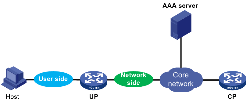
By default, when a UP receives user session information from the CP, the UP maintains the session on all cards because it cannot identify network-side cards. Although this behavior ensures successful user communication, it occupies a large amount of memory resources on the UP.
To save memory resources, you can specify a card connected to network-side interfaces as a network-side card. Then, when the UP receives user session information from the CP, it maintains the session only on the card where the access interface of the user resides and on the network-side card.
You can repeat this command to specify multiple cards as network-side cards.
You can specify an interface card but not an MPU as a network-side card.
Examples
# Specify the card in slot 3 as a network-side card.
<Sysname> system-view
[Sysname] bras network-board slot 3
cut access-user
Use cut access-user to forcibly log out users.
Syntax
In standalone mode:
cut access-user [ { auth-type { admin | bind | dot1x [ with-address | without-address ] | ppp | pre-auth | web-auth [ inherit-pppoe | non-inherit-pppoe ] } | domain domain-name | interface interface-type interface-number [ s-vlan svlan-id [ c-vlan cvlan-id ] ] | ip-pool pool-name | ip-type { dual-stack | ipv4 | ipv6 } | ipv6-pool pool-name | mac-address mac-address | user-address-type { ds-lite | ipv6 | nat64 | private-ds | private-ipv4 | public-ds | public-ipv4 } | user-profile profile-name [ both | inbound | outbound ] | username user-name | vpn-instance vpn-instance-name | vxlan vxlan-id [ vxlan-id-max ] | slot slot-number [ cpu cpu-number ] } * | { { ip-address ipv4-address | ipv6-address ipv6-address | ipv6-prefix prefix-address/prefix-length } [ vpn-instance vpn-instance-name ] | user-id user-id } ]
In IRF mode:
cut access-user [ { auth-type { admin | bind | dot1x [ with-address | without-address ] | ppp | pre-auth | web-auth [ inherit-pppoe | non-inherit-pppoe ] } | domain domain-name | interface interface-type interface-number [ s-vlan svlan-id [ c-vlan cvlan-id ] ] | ip-pool pool-name | ip-type { dual-stack | ipv4 | ipv6 } | ipv6-pool pool-name | mac-address mac-address | user-address-type { ds-lite | ipv6 | nat64 | private-ds | private-ipv4 | public-ds | public-ipv4 } | user-profile profile-name [ both | inbound | outbound ] | username user-name | vpn-instance vpn-instance-name | vxlan vxlan-id [ vxlan-id-max ] | chassis chassis-number slot slot-number [ cpu cpu-number ] } * | { { ip-address ipv4-address | ipv6-address ipv6-address | ipv6-prefix prefix-address/prefix-length } [ vpn-instance vpn-instance-name ] | user-id user-id } ]
Views
User view
Predefined user roles
network-admin
Parameters
auth-type: Specifies an authentication type for access users.
· admin: Specifies device management users.
· bind: Specifies IPoE users using bind authentication.
· dot1x: Specifies 802.1X users. If you specify the dot1x keyword but do not specify the with-address or without-address keyword, this command forcibly logs out all matching 802.1X users.
¡ with-address: Specifies IPoE users that come online in the postauthentication domain in the 802.1X authentication method. Session information about this type of users has IP address information.
¡ without-address: Specifies IPoE users that have not come online in the preauthentication domain in the 802.1X authentication method but whose 802.1X clients have come online. Session information about this type of users does not have IP address information.
· ppp: Specifies PPP users.
· pre-auth: Specifies IPoE users in the preauthentication phase.
· web-auth: Specifies IPoE users using Web authentication in the Web authentication phase.
¡ inherit-pppoe: Specifies IPoE Web users that inherit the PPPoE user information.
¡ non-inherit-pppoe: Specifies IPoE Web users except those that inherit PPPoE user information.
domain domain-name: Logs out users in the forced domain specified by its name, a case-insensitive string of 1 to 255 characters.
interface interface-type interface-number: Logs out users on an interface specified by its type and number. Only network access users support this keyword.
· s-vlan svlan-id: Logs out users in an SVLAN specified by its ID. The value range is 1 to 4094.
· c-vlan cvlan-id: Logs out users in a CVLAN specified by its ID. The value range is 1 to 4094.
ip-pool pool-name: Logs out users in an IPv4 address pool specified by its name, a case-insensitive string of 1 to 63 characters.
ip-type: Logs out users of the specified IP type.
· dual-stack: Specifies dual-stack users.
· ipv4: Specifies IPv4 users.
· ipv6: Specifies IPv6 users.
ipv6-pool pool-name: Logs out users in an IPv6 address pool specified by its name, a case-insensitive string of 1 to 63 characters. On an NDRA network, if the IPv6 prefix of a user is from the ND prefix pool, the pool-name argument represents the name of the AAA-authorized ND prefix pool.
mac-address mac-address: Logs out a user with the specified MAC address in the form of H-H-H, case-insensitive. Only network access users support this keyword.
user-address-type: Logs out users with the specified IP address type.
· ds-lite: Specifies lite dual-stack addresses.
· ipv6: Specifies IPv6 addresses.
· nat64: Specifies NAT64 addresses.
· private-ds: Specifies private dual-stack addresses.
· private-ipv4: Specifies private IPv4 addresses.
· public-ds: Specifies public dual-stack addresses.
· public-ipv4: Specifies public IPv4 addresses.
user-profile profile-name: Logs out users of a user profile specified by its name, a case-sensitive string of 1 to 31 characters. Valid characters include letters, digits, underlines (_), minus sings (-), and periods (.). A user profile name must start with a letter or digit, and cannot be all digits. If you do not specify a user profile direction, a user is logged out only if the user’s user profile matches the specified user profile in any direction.
· both: Logs a user whose profile matches the specified profile in both directions.
· inbound: Logs a user whose profile matches the specified profile in the inbound direction.
· outbound: Logs a user whose profile matches the specified profile in the outbound direction.
username user-name: Logs out a user specified by its username, a case-sensitive string of 1 to 253 characters.
vpn-instance vpn-instance-name: Logs out users in a VPN instance specified by its name, a case-sensitive string of 1 to 31 characters. If you do not specify this option, this command logs out users in the public network.
vxlan vxlan-id [ vxlan-id-max ]: Logs out users in a VXLAN specified by the vxlan-id argument or VXLAN range specified by the vxlan-id vxlan-id-max arguments The vxlan-id and vxlan-id-max arguments are both in the range of 0 to 16777215.
ip-address ipv4-address: Logs out a user with the specified IPv4 address.
ipv6-address ipv6-address: Logs out a user with the specified IPv6 address.
ipv6-prefix prefix-address/prefix-length: Logs out users with the specified IPv6 prefix. The prefix-address argument specifies the IPv6 prefix, and the prefix-length argument specifies the IPv6 prefix length.
user-id user-id: Logs out a user specified by its online index. The value range is 1 to FFFF4240 (hexadecimal).
slot slot-number: Specifies a card by its slot number. (In standalone mode.)
chassis chassis-number slot slot-number: Specifies a card on an IRF member device. The chassis-number argument represents the member ID of the IRF member device. The slot-number argument represents the slot number of the card. (In IRF mode.)
cpu cpu-number: Specifies a CPU by its number. This option is available only if multiple CPUs are available on the specified slot.
Usage guidelines
This command takes effect only on online IPoE, PPPoE, and L2TP users.
Examples
# Forcibly log out the user with IP address 10.10.10.10.
<Sysname> cut access-user ip-address 10.10.10.10
# Forcibly log out the users in ISP domain dm1.
<Sysname> cut access-user domain dm1
# Forcibly log out the user named user1.
<Sysname> cut access-user username user1
Related commands
display access-user
display access-user
Use display access-user to display access user information.
Syntax
In standalone mode:
display access-user [ [ { { [ all-vpn-instance | public-instance | vpn-instance vpn-instance-name ] | auth-type { admin | bind | dot1x [ with-address | without-address ] | ppp | pre-auth | web-auth [ inherit-pppoe | non-inherit-pppoe ] } | domain domain-name [ authorization | authentication ] | interface interface-type interface-number [ all | s-vlan svlan-id [ c-vlan cvlan-id ] ] | ip-pool pool-name | ip-pool-group ip-pool-groupname | ip-type { dual-stack | ipv4 | ipv6 } | ipv6-address-protocol { dhcpv6 | dhcpv6-pd | nd } | ipv6-cpe-mode { ipv6 | ipv6-pd } | ipv6-pool pool-name | ipv6-pool-group ipv6-pool-groupname | lac-ip lac-ip-address | lns-ip lns-ip-address | mac-address mac-address | pppoe-agency-state no-online | remote-name tunnel-name | start-time start-time start-date end-time end-time end-date | user-address-type { ds-lite | ipv6 | nat64 | private-ds | private-ipv4 | public-ds | public-ipv4 } | user-group user-group-name | user-type { lac | leased | lns | pppoe | pppoea } | username user-name | vxlan vxlan-id [ vxlan-id-max ] | slot slot-number [ cpu cpu-number ] } * | time time [ slot slot-number [ cpu cpu-number ] ] } [ count | verbose ] | { { ip-address ipv4-address | ipv6-address ipv6-address | ipv6-prefix ipv6-prefix/prefix-length | public-ip-address public-ip-address } [ all-vpn-instance | public-instance | vpn-instance vpn-instance-name ] | user-id user-id } [ slot slot-number [ cpu cpu-number ] ] [ verbose ] ] | { count | verbose } ]
In IRF mode:
display access-user [ [ { { [ all-vpn-instance | public-instance | vpn-instance vpn-instance-name ] | auth-type { admin | bind | dot1x [ with-address | without-address ] | ppp | pre-auth | web-auth [ inherit-pppoe | non-inherit-pppoe ] } | domain domain-name [ authorization | authentication ] | interface interface-type interface-number [ all | s-vlan svlan-id [ c-vlan cvlan-id ] ] | ip-pool pool-name | ip-pool-group ip-pool-groupname | ip-type { dual-stack | ipv4 | ipv6 } | ipv6-address-protocol { dhcpv6 | dhcpv6-pd | nd } | ipv6-cpe-mode { ipv6 | ipv6-pd } | ipv6-pool pool-name | ipv6-pool-group ipv6-pool-groupname | lac-ip lac-ip-address | lns-ip lns-ip-address | mac-address mac-address | pppoe-agency-state no-online | remote-name tunnel-name | start-time start-time start-date end-time end-time end-date | user-address-type { ds-lite | ipv6 | nat64 | private-ds | private-ipv4 | public-ds | public-ipv4 } | user-group user-group-name | user-type { lac | leased | lns | pppoe | pppoea } | username user-name | vxlan vxlan-id [ vxlan-id-max ] | chassis chassis-number slot slot-number [ cpu cpu-number ] } * | time time [ chassis chassis-number slot slot-number [ cpu cpu-number ] ] } [ count | verbose ] | { { ip-address ipv4-address | ipv6-address ipv6-address | ipv6-prefix ipv6-prefix/prefix-length | public-ip-address public-ip-address } [ all-vpn-instance | public-instance | vpn-instance vpn-instance-name ] | user-id user-id } [ chassis chassis-number slot slot-number [ cpu cpu-number ] ] [ verbose ] ] | { count | verbose } ]
Views
Any view
Predefined user roles
network-admin
network-operator
Parameters
all-vpn-instance: Specifies all VPN instances, excluding the public network instance.
public-instance: Specifies the public network instance.
vpn-instance vpn-instance-name: Specifies users in an MPLS L3VPN instance specified by its name, a case-sensitive string of 1 to 31 characters.
auth-type: Specifies an authentication type for access users.
· admin: Specifies device management users.
· bind: Specifies IPoE users using bind authentication.
· dot1x: Specifies 802.1X users. If you specify the dot1x keyword but do not specify the with-address or without-address keyword, this command displays information about all matching 802.1X users.
¡ with-address: Specifies IPoE users that come online in the postauthentication domain in the 802.1X authentication method. Session information about this type of users has IP address information.
¡ without-address: Specifies IPoE users that have not come online in the preauthentication domain in the 802.1X authentication method but whose 802.1X clients have come online. Session information about this type of users does not have IP address information.
· ppp: Specifies PPP users.
· pre-auth: Specifies IPoE in the preauthentication phase.
· web-auth: Specifies IPoE users using Web authentication in the Web authentication phase.
¡ inherit-pppoe: Specifies IPoE Web users that inherit PPPoE user information.
¡ non-inherit-pppoe: Specifies IPoE Web users except those that inherit PPPoE user information.
domain domain-name: Specifies users accessing through an authorization or authentication domain specified by its name, a case-insensitive string of 1 to 255 characters. If you specify the domain keyword but do not specify the authorization or authentication keyword, this command displays information about all matching users accessing through the specified authentication domain and authorization domain.
· authorization: Specifies users that access through the specified authorization domain.
· authentication: Specifies users that access through the specified authentication domain.
interface interface-type interface-number: Specifies users accessing through an interface specified by its type and number. Only network access users support this option.
· all: Displays user information on the current main interface and all its subinterfaces. To specify this keyword, make sure the interface specified by using the interface keyword is a main interface and you must also specify the count keyword.
· s-vlan svlan-id: Specifies an SVLAN by its ID. The value range is 1 to 4094.
· c-vlan cvlan-id: Specifies a CVLAN by its ID. The value range is 1 to 4094.
ip-pool pool-name: Specifies users in an IPv4 address pool specified by its name, a case-insensitive string of 1 to 63 characters.
ip-pool-group ip-pool-groupname: Specifies users in an IPv4 address pool group specified by its name, a case-insensitive string of 1 to 63 characters.
ip-type: Specifies users of an IP type.
· dual-stack: Specifies dual-stack users.
· ipv4: Specifies IPv4 users.
· ipv6: Specifies IPv6 users.
ipv6-address-protocol: Specifies users whose IPv6 addresses or prefixes are assigned by the specified IPv6 protocol.
· dhcpv6: Specifies users whose address are assigned by DHCPv6.
· dhcpv6-pd: Specifies IPv6 PD prefixes allocated to users by using DHCPv6.
· nd: Specifies users whose address are assigned by IPv6 NDRA.
ipv6-cpe-mode: Specifies CPE users. In an NDRA+IA_PD or IA_NA+IA_PD hybrid network, you cannot specify the ipv6-cpe-mode keyword to search for access users.
· ipv6: Specifies access users that obtain IPv6 addresses through NDRA or IA_NA.
· ipv6-pd: Specifies access users that obtain IPv6 PD prefixes through IA_PD.
ipv6-pool pool-name: Specifies users in an IPv6 address pool specified by its name, a case-insensitive string of 1 to 63 characters. On an NDRA network, if the IPv6 prefix of a user is from the ND prefix pool, the pool-name argument represents the name of the AAA-authorized ND prefix pool.
ipv6-pool-group ipv6-pool-groupname: Specifies users in an IPv6 address pool group by its name, a case-insensitive string of 1 to 63 characters.
lac-ip lac-ip-address: Specifies the LNS to display users on the LAC specified by its IP address. Only the LNS supports this option.
lns-ip lns-ip-address: Specifies the LAC to display users on the LNS specified by its IP address. Only the LAC supports this option.
mac-address mac-address: Specifies a user by its MAC address in H-H-H format, case-insensitive. Only network access users support this option.
pppoe-agency-state: Specifies internal campus access authentication users (for example, IPoE users) in the specified PPPoE agency state.
no-online: Specifies internal campus access authentication users with the PPPoE agency state as not online.
remote-name tunnel-name: Specifies an L2TP user of the LAC or LNS specified by its tunnel name, a string of 1 to 31 characters.
start-time start-time start-date end-time end-time end-date: Specifies users within the specified time range. The start-time start-time start-date option specifies the start time and date. The end-time start-time start-date option specifies the end time and date.
· The start-time and end-time arguments are in the HH:MM:SS format. HH specifies an hour in the range of 0 to 23. MM specifies a minute in the range of 0 to 59. SS specifies a second in the range of 0 to 59. To specify an integer hour, you do not need to specify the minute or second. To specify an integer minute, you do not need to specify the second. For example, if you enter 0 or 0:0, the time is hour 0 minute 0 second 0.
· The start-date and end-date arguments are in the MM/DD/YYYY or YYYY/MM/DD format. MM specifies a month in the range of 1 to 12. DD specifies a day and its value range varies by month. YYYY specifies a year in the range of 2000 to 2035.
user-address-type: Specifies users with addresses of the specified type.
· ds-lite: Specifies lite dual-stack addresses.
· ipv6: Specifies IPv6 addresses.
· nat64: Specifies NAT64 addresses.
· private-ds: Specifies private dual-stack addresses.
· private-ipv4: Specifies private IPv4 addresses.
· public-ds: Specifies public dual-stack addresses.
· public-ipv4: Specifies public IPv4 addresses.
user-group user-group-name: Specifies users in a user group specified by its name, a case-insensitive string of 1 to 32 characters.
user-type: Specifies users of the specified type.
· lac: Specifies users on the device acting as a LAC.
· leased: Specifies IPoE leased users.
· lns: Specifies users on the device acting as an LNS.
· pppoe: Specifies PPPoE users.
· pppoea: Specifies PPPoEA users.
username user-name: Specifies a user by its name, a case-sensitive string of 1 to 253 characters.
vxlan vxlan-id [ vxlan-id-max ]: Specifies users in the specified VXLANs. The vxlan-id argument and the vxlan-id-max argument specify the start VXLAN ID and end VXLAN ID, respectively, each in the range of 1 to 16777215.
time time: Specifies users accessing with the specified time range. The time argument specifies a duration in the range of 1 to 7200 seconds. For example, if you set the time argument to 2000, this command displays users coming online with the latest 2000 seconds.
ip-address ipv4-address: Specifies the user with the specified IPv4 address.
ipv6-address ipv6-address: Specifies the user with the specified IPv6 address.
ipv6-prefix ipv6-prefix: Specifies users with the specified IPv6 prefix (IPv6 ND prefix or IPv6 PD prefix). The ipv6-prefix argument specifies an IPv6 prefix. The prefix-length argument specifies an IPv6 prefix length.
public-ip-address public-ip-address: Specifies a NAT user by the public IP address assigned to the user in the NAT network.
user-id user-id: Specifies an online user by its index, a hexadecimal number in the range of 1 to FFFF4240.
count: Displays the number of users.
verbose: Displays detailed user information. This keyword is supported only by IPoE, PPPoE, and L2TP users.
slot slot-number: Specifies a card by its slot number. (In standalone mode.)
chassis chassis-number slot slot-number: Specifies a card on an IRF member device. The chassis-number argument represents the member ID of the IRF member device. The slot-number argument represents the slot number of the card. (In IRF mode.)
cpu cpu-number: Specifies a CPU by its number. This option is available only if multiple CPUs are available on the specified slot.
Usage guidelines
If you do not specify the count or verbose keyword, this command displays brief user information.
If you do not specify any of the all-vpn-instance, public-instance, and vpn-instance keywords, this command displays user information of the public network instance and all VPN instances.
In an L2TP network, this command is supported on an LAC only if a remote system dials in to the LAC through a PPPoE network. For more information about L2TP, see L2TP configuration in BRAS Services Configuration Guide .
Examples
# Display the number of all access users.
<Sysname> display access-user count
Total users : 5
PPPoE users : 0
PPPoEA users : 0
PPPoA users : 0
PPPoFR users : 0
PPPoPhy users : 0
LNS users : 0
LAC users : 0
VPPP users : 0
L2 IPoE dynamic users : 1
L2 IPoE static users : 0
L2 IPoE interface leased users : 0
L2 IPoE subnet leased users : 0
L2 IPoE leased subusers : 0
IPoE L2VPN leased users : 0
L3 IPoE dynamic users : 0
L3 IPoE static users : 0
L3 IPoE interface leased users : 0
L3 IPoE subnet leased users : 0
Web auth users : 0
Portal users : 0
Telnet users : 1
SSH users : 0
HTTP users : 1
HTTPS users : 1
FTP users : 1
Command users : 0
PAD users : 0
Terminal users : 0
MAC auth users : 0
Dot1X users : 0
IKE users : 0
SSLVPN users : 0
DVPN users : 0
|
Field |
Description |
|
Total users |
Total number of users (excluding LAC users). |
|
PPPoE users |
Number of PPPoE users. |
|
PPPoEA users |
Number of PPPoEA users. |
|
PPPoA users |
This field is not supported in the current software version. Number of PPPoA users. |
|
PPPoFR users |
This field is not supported in the current software version. Number of PPPoFR users. |
|
PPPoPhy users |
Number of PPP access users directly carried on physical links. |
|
LNS users |
Number of L2TP users on the LNS. |
|
LAC users |
Number of L2TP users on the LAC. For example, PPPoE users that trigger the LAC to set up L2TP tunnels in NAS-initiated mode and LNS users on the LTS. |
|
VPPP users |
Number of L2TP users automatically dialing on the LAC. |
|
L2 IPoE dynamic users |
Number of Layer 2 IPoE dynamic users (including IPoE users using 802.1X authentication in the postauthentication phase. |
|
L2 IPoE static users |
Number of Layer 2 IPoE static users, including static individual users, static leased users, and IPoE users using 802.1X authentication in the postauthentication phase. |
|
L2 IPoE interface leased users |
Number of Layer 2 IPoE interface-leased users. |
|
L2 IPoE subnet leased users |
Number of Layer 2 IPoE subnet-leased users. |
|
L2 IPoE leased subusers |
Number of Layer 2 IPoE leased subusers. |
|
IPoE L2VPN leased users |
Number of IPoE L2VPN-leased users. |
|
L3 IPoE dynamic users |
Number of Layer 3 IPoE dynamic users. |
|
L3 IPoE static users |
Number of Layer 3 IPoE static users, including static individual users and static leased users. |
|
L3 IPoE interface leased users |
Number of Layer 3 IPoE interface-leased users. |
|
L3 IPoE subnet leased users |
Number of Layer 3 IPoE subnet-leased users. |
|
Web auth users |
Number of Web authentication users. |
|
Portal users |
This field is not supported in the current software version. Number of portal users. |
|
Telnet users |
Number of Telnet users. |
|
SSH users |
Number of SSH users. |
|
HTTP users |
Number of HTTP users. |
|
HTTPS users |
Number of HTTPS users. |
|
FTP users |
Number of FTP users. |
|
Command users |
Number of command authorization and accounting users. |
|
PAD users |
This field is not supported in the current software version. Number of PAD users. |
|
Terminal users |
Number of uses logging in through the Console port, AUX port, and Asyn port. |
|
MAC auth users |
This field is not supported in the current software version. Number of MAC authentication users. |
|
Dot1X users |
This field is not supported in the current software version. Number of Layer 2 802.1X users. |
|
IKE users |
This field is not supported in the current software version. Number of IKE users. |
|
SSLVPN users |
This field is not supported in the current software version. Number of SSL VPN users. |
|
DVPN users |
This field is not supported in the current software version. Number of DVPN users. |
# Display brief information about all access users.
<Sysname> display access-user
UserID Interface IP address MAC address S-/C-VLAN
Username Access type
IPv6 address
0x33d BAS0 192.168.0.2 - -/-
user1 LNS
-
0x33e XGE3/1/1 3.3.3.3 001b-21a8-0949 -/-
user2 L2 IPoE dynamic
-
0x33e XGE3/1/1 5.3.3.3 001b-21a8-0950 -/-
User3 L3 IPoE static
-
0x33f XGE3/1/1 192.168.0.3 001b-21a8-0951 -/-
user3 PPPoE
-
0x400005 - 3.3.3.3 - -/-
user4 Telnet
-
0x400006 - 3.3.3.3 - -/-
user5 FTP
-
0x400007 - 3.3.3.3 - -/-
user6 HTTP
-
0x400008 - 3.3.3.3 - -/-
user7 HTTPS
-
Table 2 Command output
|
Field |
Description |
|
UserID |
Online index of a user. |
|
Interface |
Access interface of a user. If the user does not have an access interface, this field displays a hyphen (-). |
|
Username |
Username for authentication. If the username contains more than 20 characters, the username is displayed in the format of “the first 20 characters in the username+...” in the brief information. |
|
IP address |
IPv4 address of a user. If the user does not have an IPv4 address, this field displays a hyphen (-). For a PPPoEA user, this field displays the IP address allocated to the PPPoEA user by the ISP. |
|
IPv6 address |
IPv6 address of a user. If the user does not have an IPv6 address, this field displays a hyphen (-). |
|
MAC address |
MAC address of a user. If the user does not have a MAC address, this field displays a hyphen (-). For a PPPoEA user, this field displays the MAC address of the BRAS user that dials up for the PPPoEA user. |
|
S-/C-VLAN |
SVLAN and CVLAN of a user. If the user does not have a SVLAN or CVLAN, this field displays -/-. |
|
Access type |
Access type of a user. For more information, see Table 1. |
#(Individual users.) Display detailed information about IPoE users using bind authentication.
<Sysname> display access-user auth-type bind verbose
Basic:
Description: N/A
User ID: 0x33e
Username: user1
Backup role: N/A
Authorization domain: dm1
Authentication domain: dm1
Interface: XGE3/1/1
Service-VLAN/Customer-VLAN: -/-
VXLAN ID: -
MAC address: 001b-21a8-0949
IP address: 3.3.3.3
IP pool: pool1
Primary DNS server: -
Secondary DNS server: -
IPv6 address: -
IPv6 pool: N/A
Primary IPv6 DNS server: -
Secondary IPv6 DNS server: -
IPv6 PD prefix: -
IPv6 ND prefix: -
IPv6 ND prefix pool: N/A
DHCP lease: -
DHCP remaining lease: -
DHCPv6 lease: -
DHCPv6 remaining lease: -
User address type: N/A
VPN instance: N/A
Access type: L2 IPoE dynamic
Authentication type: Bind
Static leased user: No
Agent-Circuit-Id: -
Agent-Remote-Id: -
NAS-Port-Id: slot=1;subslot=0;port=1;vlanid=0;
User IPv6CP interface ID: -
AAA:
Authentication state: Authenticated
Authorization state: Authorized
Realtime accounting switch: Closed
Realtime accounting interval: -
Login time: 2019-09-21 13:55:57
Accounting start time: 2019-09-21 13:55:57
Online time (hh:mm:ss): 0:02:19
Accounting state: Accounting
Acct start-fail action: Online
Acct update-fail action: Online
Acct quota-out action: Offline
Dual-stack accounting mode: Merge
Idle cut: 0 seconds 0 bytes, direction: Both
Session timeout: Unlimited
Time remained: Unlimited
Traffic quota: Unlimited
Traffic remained: Unlimited
IPv6CP interface ID assignment: Disabled
Redirect WebURL: -
Redirect IPv6 WebURL: -
ITA policy name: N/A
MRU: N/A
IPv4 MTU: N/A
IPv6 MTU: N/A
Subscriber ID: -
Inbound netstream sampler: Not set
Outbound netstream sampler: Not set
IPv4 multicast user profile: N/A
IPv6 multicast user profile: N/A
User session: limit 2, online 1
Account ID: 0x2
ACL&QoS:
Inbound user profile: N/A
Outbound user profile: N/A
Session group profile: N/A
User group acl: N/A
Inbound CAR: -
Outbound CAR: -
Inbound user priority: -
Outbound user priority: -
Flow Statistic:
Uplink packets/bytes: 389/50005
Downlink packets/bytes: 23/1362
IPv6 uplink packets/bytes: 0/0
IPv6 downlink packets/bytes: 0/0
ITA:
Level-1 Uplink packets/bytes : 4/392
Downlink packets/bytes : 4/392
IPv6 uplink packets/bytes : 0/0
IPv6 downlink packets/bytes : 0/0
Level-2 Uplink packets/bytes : 0/0
Downlink packets/bytes : 0/0
IPv6 uplink packets/bytes : 0/0
IPv6 downlink packets/bytes : 0/0
#(Static leased users.) Display detailed information about IPoE users using bind authentication.
<Sysname> display access-user auth-type bind verbose
Basic:
Description: N/A
User ID: 0x33e
Username: user1
Backup role: N/A
Authorization domain: dm1
Authentication domain: dm1
Interface: XGE3/1/1
Service-VLAN/Customer-VLAN: -/-
VXLAN ID: -
MAC address: 001b-21a8-0949
IP address: 3.3.3.3
IP pool: pool1
Primary DNS server: -
Secondary DNS server: -
IPv6 address: -
IPv6 pool: N/A
Primary IPv6 DNS server: -
Secondary IPv6 DNS server: -
IPv6 PD prefix: -
IPv6 ND prefix: -
DHCP lease: -
DHCP remaining lease: -
DHCPv6 lease: -
DHCPv6 remaining lease: -
User address type: N/A
VPN instance: N/A
Access type: L3 IPoE static
Authentication type: Bind
Static leased user: Yes
Agent-Circuit-Id: -
Agent-Remote-Id: -
NAS-Port-Id: slot=1;subslot=0;port=1;vlanid=0;
User IPv6CP interface ID: -
AAA:
Authentication state: Authenticated
Authorization state: Authorized
Realtime accounting switch: Closed
Realtime accounting interval: -
Login time: 2019-09-21 13:55:57
Accounting start time: 2019-09-21 13:55:57
Online time (hh:mm:ss): 0:02:19
Accounting state: Accounting
Acct start-fail action: Online
Acct update-fail action: Online
Acct quota-out action: Offline
Dual-stack accounting mode: Merge
Idle cut: 0 seconds 0 bytes, direction: Both
Session timeout: Unlimited
Time remained: Unlimited
Traffic quota: Unlimited
Traffic remained: Unlimited
IPv6CP interface ID assignment: Disabled
Redirect WebURL: -
Redirect IPv6 WebURL: -
ITA policy name: N/A
MRU: N/A
IPv4 MTU: N/A
IPv6 MTU: N/A
Subscriber ID: -
Inbound netstream sampler: Not set
Outbound netstream sampler: Not set
IPv4 multicast user profile: N/A
IPv6 multicast user profile: N/A
User session: limit 2, online 1
Account ID: 0x2
ACL&QoS:
Inbound user profile: N/A
Outbound user profile: N/A
Session group profile: N/A
User group acl: N/A
Inbound CAR: -
Outbound CAR: -
Inbound user priority: -
Outbound user priority: -
Flow Statistic:
Uplink packets/bytes: 389/50005
Downlink packets/bytes: 23/1362
IPv6 uplink packets/bytes: 0/0
IPv6 downlink packets/bytes: 0/0
#(Leased users.) Display detailed information about IPoE users using bind authentication.
<Sysname> display access-user auth-type bind verbose
Basic:
Description: N/A
User ID: 0x1
Username: user1
Backup role: N/A
Authorization domain : dm1
Authentication domain: dm1
Interface: XGE3/1/1
Service-VLAN/Customer-VLAN: -/-
VXLAN ID: -
MAC address: -
IP address: -
IP pool: N/A
Primary DNS server: -
Secondary DNS server: -
IPv6 address: -
IPv6 pool: N/A
Primary IPv6 DNS server: -
Secondary IPv6 DNS server: -
IPv6 PD prefix: -
IPv6 ND prefix: -
IPv6 ND prefix pool: N/A
DHCP lease: -
DHCP remaining lease: -
DHCPv6 lease: -
DHCPv6 remaining lease: -
User address type: N/A
VPN instance: N/A
Access type: L2 IPoE interface leased
Authentication type: Bind
Static leased user: No
Agent-Circuit-Id: -
Agent-Remote-Id: -
NAS-Port-Id: slot=1;subslot=0;port=1;vlanid=0;
User IPv6CP interface ID: -
AAA:
Authentication state: Authenticated
Authorization state: Authorized
Realtime accounting switch: Closed
Realtime accounting interval: -
Login time: 2019-11-19 10:15:40
Accounting start time: 2019-11-19 10:15:40
Online time(hh:mm:ss): 0:33:54
Accounting state: Accounting
Acct start-fail action: Online
Acct update-fail action: Online
Acct quota-out action: Offline
Dual-stack accounting mode: Merge
Idle cut: 0 seconds 0 bytes, direction: Both
Session timeout: Unlimited
Time remained: Unlimited
Traffic quota: Unlimited
Traffic remained: Unlimited
IPv6CP interface ID assignment: Disabled
Redirect WebURL: -
Redirect IPv6 WebURL: -
ITA policy name: N/A
MRU: N/A
IPv4 MTU: N/A
IPv6 MTU: N/A
Subscriber ID: -
Inbound netstream sampler: Not set
Outbound netstream sampler: Not set
IPv4 multicast user profile: N/A
IPv6 multicast user profile: N/A
ACL&QoS:
Inbound user profile: N/A
Outbound user profile: N/A
Session group profile: N/A
User group ACL: N/A
Inbound CAR: -
Outbound CAR: -
Inbound user priority: -
Outbound user priority: -
Flow Statistic:
Uplink packets/bytes: 4/392
Downlink packets/bytes: 4/392
IPv6 uplink packets/bytes: 0/0
IPv6 downlink packets/bytes: 0/0
Total subusers: 1
UserID IP address MAC address S-/C-VLAN
IPv6 address
0xc 1.1.1.2 6c45-4eea-0206 -/-
-
Basic:
Description: N/A
User ID: 0xc
Username: user1
Backup role: N/A
Authorization domain : dm1
Authentication domain: N/A
Interface: XGE3/1/1
Service-VLAN/Customer-VLAN: -/-
VXLAN ID: -
MAC address: 6c45-4eea-0206
IP address: 1.1.1.2
IP pool: N/A
Primary DNS server: -
Secondary DNS server: -
IPv6 address: -
IPv6 pool: N/A
Primary IPv6 DNS server: -
Secondary IPv6 DNS server: -
IPv6 PD prefix: -
IPv6 ND prefix: -
IPv6 ND prefix pool: N/A
DHCP lease: -
DHCP remaining lease: -
DHCPv6 lease: -
DHCPv6 remaining lease: -
User address type: N/A
VPN instance: N/A
Access type: L2 IPoE leased subusers
Authentication type: Bind
Static leased user: No
Agent-Circuit-Id: -
Agent-Remote-Id: -
NAS-Port-Id: slot=1;subslot=0;port=1;vlanid=0;
User IPv6CP interface ID: -
AAA:
Authentication state: -
Authorization state: -
Realtime accounting switch: Closed
Realtime accounting interval: -
Login time: 2019-11-19 10:32:09
Accounting start time: -
Online time(hh:mm:ss): 0:00:00
Accounting state: Stop
Acct start-fail action: Online
Acct update-fail action: Online
Acct quota-out action: Offline
Dual-stack accounting mode: N/A
Idle cut: 0 seconds 0 bytes, direction: Both
IPv6CP interface ID assignment: Disabled
Redirect WebURL: -
Redirect IPv6 WebURL: -
ITA policy name: N/A
MRU: N/A
IPv4 MTU: N/A
IPv6 MTU: N/A
Subscriber ID: -
Inbound netstream sampler: Not set
Outbound netstream sampler: Not set
IPv4 multicast user profile: N/A
IPv6 multicast user profile: N/A
ACL&QoS:
Inbound user profile: N/A
Outbound user profile: N/A
Session group profile: N/A
User group ACL: N/A
Inbound CAR: -
Outbound CAR: -
Inbound user priority: -
Outbound user priority: -
Flow Statistic:
Uplink packets/bytes: 0/0
Downlink packets/bytes: 0/0
IPv6 uplink packets/bytes: 0/0
IPv6 downlink packets/bytes: 0/0
#Display detailed information about PPP access users.
<Sysname> display access-user auth-type ppp verbose
Basic:
Description: N/A
PPP index: 0x22d0a92580000105
User ID: 0x33d
Username: user1
Backup role: N/A
Authorization domain: dm1
Authentication domain: dm1
Interface: BAS0
Service-VLAN/Customer-VLAN: -/-
VXLAN ID: -
MAC address: -
IP address: 192.168.0.2
IP pool: pool1
Primary DNS server: 8.8.8.8
Secondary DNS server: -
IPv6 address: 8::8
IPv6 pool: pool1
Primary IPv6 DNS server: -
Secondary IPv6 DNS server: -
IPv6 PD prefix: -
IPv6 ND prefix: -
IPv6 ND prefix pool: N/A
DHCP lease: -
DHCP remaining lease: -
DHCPv6 lease: -
DHCPv6 remaining lease: -
User address type: N/A
VPN instance: N/A
Access type: LNS
Authentication type: PPP
Agent-Circuit-Id: -
Agent-Remote-Id: -
NAS-Port-Id: slot=1;subslot=0;port=1;vlanid=0;
User IPv6CP interface ID: 1e2f:c3e4:3333:1234
L2TP LNS:
Group ID: 1
Local tunnel ID: 8912
Remote tunnel ID: 2
Local session ID: 43301
Remote session ID: 1
Local IP: 3.3.3.1
Remote IP: 3.3.3.3
Local port: 1701
Remote port: 1701
Vrf index: 0
Calling station: 9a4d-e968-0116 XGE3/1/1:ffff.ffff
AAA:
Authentication state: Authenticated
Authorization state: Authorized
Realtime accounting switch: Closed
Realtime accounting interval: -
Login time: 2019-09-21 13:54:52
Accounting start time: 2019-09-21 13:54:52
Online time (hh:mm:ss): 0:03:24
Accounting state: Accounting
Acct start-fail action: Online
Acct update-fail action: Online
Acct quota-out action: Offline
Dual-stack accounting mode: Merge
Idle cut: 0 seconds 0 bytes, direction: Both
Session timeout: Unlimited
Time remained: Unlimited
Traffic quota: Unlimited
Traffic remained: Unlimited
IPv6CP interface ID assignment: Enabled
Redirect WebURL: -
Redirect IPv6 WebURL: -
ITA policy name: N/A
MRU: 1400 bytes
IPv4 MTU: 1400 bytes
IPv6 MTU: 1400 bytes
Subscriber ID: -
Inbound netstream sampler: Not set
Outbound netstream sampler: Not set
IPv4 multicast user profile: N/A
IPv6 multicast user profile: N/A
ACL&QoS:
Inbound user profile: N/A
Outbound user profile: N/A
Session group profile: N/A
User group acl: N/A
Inbound CAR: -
Outbound CAR: -
Inbound user priority: -
Outbound user priority: -
Flow Statistic:
Uplink packets/bytes: 691/57955
Downlink packets/bytes: 0/0
IPv6 uplink packets/bytes: 0/0
IPv6 downlink packets/bytes: 0/0
Basic:
Description: N/A
PPP index: 0x140000002
User ID: 0x33f
Username: user2
Backup role: N/A
Authorization domain: dm2
Authentication domain: dm2
Interface: XGE3/1/1
Service-VLAN/Customer-VLAN: -/-
VXLAN ID: -
MAC address: 001b-21a8-0949
IP address: 192.168.0.3
IP pool: pool1
Primary DNS server: 8.8.8.8
Secondary DNS server: -
IPv6 address: 192::1
IPv6 pool: pool1
Primary IPv6 DNS server: 8::8
Secondary IPv6 DNS server: -
IPv6 PD prefix: -
IPv6 ND prefix: -
IPv6 ND prefix pool: N/A
DHCP lease: -
DHCP remaining lease: -
DHCPv6 lease: -
DHCPv6 remaining lease: -
User address type: N/A
VPN instance: N/A
Access type: PPPoE
Authentication type: PPP
Agent-Circuit-Id: -
Agent-Remote-Id: -
NAS-Port-Id: slot=1;subslot=0;port=1;vlanid=0;
User IPv6CP interface ID: 1e2f:c3e4:3333:1234
PPPoE:
Session ID: 1
AAA:
Authentication state: Authenticated
Authorization state: Authorized
Realtime accounting switch: Closed
Realtime accounting interval: -
Login time: 2019-09-21 13:57:07
Accounting start time: 2019-09-21 13:57:07
Online time (hh:mm:ss): 0:01:09
Accounting state: Accounting
Acct start-fail action: Online
Acct update-fail action: Online
Acct quota-out action: Offline
Dual-stack accounting mode: Merge
Idle cut: 0 seconds 0 bytes, direction: Both
Session timeout: Unlimited
Time remained: Unlimited
Traffic quota: Unlimited
Traffic remained: Unlimited
IPv6CP interface ID assignment: Enabled
Redirect WebURL: -
Redirect IPv6 WebURL: -
ITA policy name: N/A
MRU: 1480 bytes
IPv4 MTU: 1480 bytes
IPv6 MTU: 1480 bytes
Subscriber ID: -
Inbound netstream sampler: Not set
Outbound netstream sampler: Not set
IPv4 multicast user profile: N/A
IPv6 multicast user profile: N/A
ACL&QoS:
Inbound user profile: N/A
Outbound user profile: N/A
Session group profile: N/A
User group acl: N/A
Inbound CAR: -
Outbound CAR: -
Inbound user priority: -
Outbound user priority: -
NAT:
Global IP address: 111.8.0.200
Port block: 28744-28748
Extended port block: 2024-2033/3024-3033/4024-4033/5024-5033/6024-6033
Flow Statistic:
Uplink packets/bytes: 28/4736
Downlink packets/bytes: 0/0
IPv6 uplink packets/bytes: 0/0
IPv6 downlink packets/bytes: 0/0
EDSG:
Service ID : 1
Uplink packets/bytes : 4/392
Downlink packets/bytes : 4/392
IPv6 uplink packets/bytes : 0/0
IPv6 downlink packets/bytes : 0/0
Service ID : 2
Uplink packets/bytes : 0/0
Downlink packets/bytes : 0/0
IPv6 uplink packets/bytes : 0/0
IPv6 downlink packets/bytes : 0/0
Table 3 Command output
|
Field |
Description |
|
Basic |
Basic information of a user. |
|
Description |
Description of a user. If the user does not have a description, this field displays N/A. |
|
PPP index |
PPP session index. This field is displayed only for PPPoE users and L2TP users. |
|
Username |
Username for authentication. |
|
Backup role |
This field is not supported in the current software version. Role of the user in the VSRP network: · Master—In the VSRP network, the user belongs to the master device. · Backup—In the VSRP network, the user belongs to the backup device, and the user information is synchronized from the master device. · N/A—The user is not in a VSRP network. |
|
Authorization domain |
Authorization domain, which specifies the ISP domain that the AAA server authorizes to the user through the H3C-ISP-ID attribute. The authorization domain is the actual ISP domain that the user uses after coming online. |
|
Authentication domain |
Authentication domain, which specifies the domain used by the user for authentication on the AAA server. For Layer 2 IPoE leased subusers, who do not need authentication, this field displays N/A. |
|
Interface |
Access interface of a user. If the user does not have an access interface, this field displays a hyphen (-). |
|
Backup interface |
UP backup access interface of a user. If the user does not have a UP backup access interface, this field is not displayed. |
|
Service-VLAN/Customer-VLAN |
SVLAN and CVLAN of a user. If the user does not have a SVLAN or CVLAN, this field displays -/-. |
|
VXLAN ID |
VXLAN ID. If the user does not have a VXLAN ID, this field displays a hyphen (-). |
|
MAC address |
MAC address. If the user does not have a MAC address, this field displays a hyphen (-). For a PPPoEA user, this field displays the MAC address of the BRAS user that dials up for the PPPoEA user. |
|
IP address |
IPv4 address of the user. If the user does not have an IPv4 address, this field displays a hyphen (-). For a PPPoEA user, this field displays the IP address allocated to the PPPoEA user by the ISP. |
|
IP pool |
Name of the IP address pool actually used by the user (this field displays N/A if the user does not use an IP address pool). The value displayed for this field depends on the origins of the IP address pool as follows: · If AAA authorizes an IP address pool but does not authorize an IP address pool group, the field displays the name of the AAA-authorized IP address pool. · If AAA does not authorize an IP address pool but authorizes an IP address pool group, the field displays the name of the IP address pool allocated from the AAA-authorized IP address pool group to the user. · If AAA authorizes both an IP address pool and an IP address pool group, the field displays the name of the AAA-authorized IP address pool. · If AAA does not authorize an IP address pool or IP address pool group, the field displays the name of the IP address pool selected through DHCP. For more information about how DHCP selects an IP address pool, see DHCP configuration in BRAS Services Configuration Guide. |
|
IP pool group |
AAA-authorized IP address pool group name. This field is displayed when AAA authorizes an IP address pool group. |
|
Primary DNS server |
Primary IPv4 DNS server address. This field displays a hyphen (-) when the address does not exist. |
|
Secondary DNS server |
Secondary IPv4 DNS server address. This field displays a hyphen (-) when the address does not exist. |
|
IPv6 address |
IPv6 address of the user. If the user does not have an IPv6 address, this field displays a hyphen (-). |
|
IPv6 pool |
Name of the IPv6 address pool actually used by the user (this field displays N/A if the user does not use an IPv6 address pool). The value displayed for this field depends on the origins of the IPv6 address pool as follows: · If AAA authorizes an IPv6 address pool but does not authorize an IPv6 address pool group, the field displays the name of the AAA-authorized IPv6 address pool. · If AAA does not authorize an IPv6 address pool but authorizes an IPv6 address pool group, the field displays the name of the IPv6 address pool allocated from the AAA-authorized IPv6 address pool group to the user. · If AAA authorizes both an IPv6 address pool and an IPv6 address pool group, the field displays the name of the AAA-authorized IPv6 address pool. · If AAA does not authorize an IPv6 address pool or IPv6 address pool group, the field displays the name of the IPv6 address pool selected through DHCP. For more information about how DHCP selects an IPv6 address pool, see DHCPv6 configuration in BRAS Services Configuration Guide. |
|
IPv6 pool group |
AAA-authorized IPv6 address pool group name. This field is displayed when AAA authorizes an IPv6 address pool group. |
|
Primary IPv6 DNS server |
Primary IPv6 DNS server address. This field displays a hyphen (-) when the address does not exist. |
|
Secondary IPv6 DNS server |
Secondary IPv6 DNS server address. This field displays a hyphen (-) when the address does not exist. |
|
IPv6 PD prefix |
IPv6 PD prefix of the user. If the user does not have an IPv6 PD prefix, this field displays a hyphen (-). |
|
IPv6 ND prefix |
IPv6 ND prefix of the user. If the user does not have an IPv6 ND prefix, this field displays a hyphen (-). |
|
IPv6 ND prefix pool |
Name of the AAA-authorized IPv6 ND prefix pool. (This field displays N/A if the no IPv6 ND prefix pool is authorized). The value displayed for this field depends on the origins of the IPv6 ND prefix pool: · If AAA authorizes an IPv6 ND prefix pool but does not authorize an IPv6 ND prefix pool group, the field displays the name of the AAA-authorized IPv6 ND prefix pool. · If AAA does not authorize an IPv6 ND prefix pool but authorizes an IPv6 ND prefix pool group, the field displays the name of the IPv6 ND prefix pool allocated from the AAA-authorized IPv6 ND prefix pool group to the user. · If AAA authorizes both an IPv6 ND prefix pool and an IPv6 ND prefix pool group, the field displays the name of the AAA-authorized IPv6 ND prefix pool. |
|
IPv6 ND prefix pool group |
Name of the AAA-authorized IPv6 ND prefix pool group. This field is displayed only when AAA authorizes an IPv6 ND prefix pool group. |
|
DHCP lease |
DHCP-authorized IP lease in seconds (this field is displayed only in common mode or in control plane mode of the CUPS mode): · Hyphen (-)—No IP lease is authorized. · Unlimited—The IP lease is unlimited. |
|
DHCP remaining lease |
Remaining DHCP-authorized IP lease in seconds. This field is displayed only in common mode or in control plane mode of the CUPS mode. This field is displayed only on the service node. On the other nodes, this field displays a hyphen (-). |
|
DHCPv6 lease |
DHCPv6-authorized IPv6 lease in seconds (this field is displayed only in common mode or in control plane mode of the CUPS mode and when IPv6 users are online): · Hyphen (-)—No IPv6 lease is authorized. · Unlimited—The IPv6 lease is unlimited. |
|
DHCPv6 remaining lease |
Remaining DHCPv6-authorized IPv6 lease in seconds. This field is displayed only in common mode or in control plane mode of the CUPS mode and when IPv6 users are online. This field is displayed only on the service node. On the other nodes, this field displays a hyphen (-). |
|
User address type |
AAA-authorized user address type: · private-ds—Private dual-stack address. · private-ipv4—Private IPv4 address. · public-ds—Public dual-stack address. · public-ipv4—Public IPv4 address. · ds-lite—Lite dual-stack address. · ipv6—IPv6 address. · nat64—NAT64 address. · N/A—If no IPv4 user address type is authorized, this field displays N/A. |
|
VPN instance |
VPN instance of the user. If the user belongs to a public network, this field displays N/A. |
|
Access type |
Access type of the user. For more information, see Table 1. |
|
Authentication type |
Authentication type of the user: · Admin—Device management users. · Bind—IPoE users using bind authentication. · PPP—PPP users. · Pre-auth—IPoE users in preauthentication phase. · SSLVPN—SSL VPN users. · Web-auth—IPoE users in Web authentication phase and users performing authentication through a Web interface on a Layer 2 Ethernet interface. |
|
Inherit-PPPoE user: Yes |
The current IPoE Web user directly inherits the PPPoE user information in the preauthentication domain and comes online in the postauthentication domain. This field is displayed only when the IPoE Web user inherits the PPPoE user information and comes online in the postauthentication domain. |
|
Static leased user |
Whether the user is an IPoE static leased user. This field displays Yes for static leased users and No for the other users. (Static leased sessions are supported only when the bind authentication mode is used on a non-CUPS network.) |
|
Agent-Circuit-Id |
Circuit ID. If no circuit ID exists, this field displays a hyphen (-). |
|
Agent-Remote-Id |
Remote ID. If no remote ID exists, this field displays a hyphen (-). |
|
NAS-Port-Id |
Information encapsulated in the NAS-Port-ID attribute. If no circuit ID NAS-Port-ID attribute information exists, this field displays a hyphen (-). For a leased user or subuser, this field always displays the NAS-Port-ID of the leased user. This field displays the NAS-Port-ID encapsulation format defined by each service module and is not affected by the attribute 87 format command configuration. For more information about this command, see AAA commands. |
|
User IPv6CP interface ID |
Interface ID used by a PPP user after the IPv6CP negotiation succeeds. If the user does not have an interface ID, this field displays a hyphen (-). The interface IDs used by PPP users include the following types, in descending order of priority: 1. Interface ID authorized by the RADIUS server through the Framed-Interface-Id attribute. 2. The lowest 64 bits of the authorized IPv6 address if an IPv6 address is authorized to the user but no IPv6 prefix is authorized to the user when NDRA is used to allocate IPv6 addresses to PPP users. 3. Interface ID automatically assigned by the device when the ipv6cp assign-interface-id command is executed in the ISP domain of the user. If the ipv6cp assign-interface-id command is not executed in the ISP domain of the user, the following rules apply: · If the user carries a non-zero interface ID that does not conflict with any other interface ID, the interface carried by the user is used. · Otherwise, the interface ID assigned by the device is used. |
|
AAA |
AAA information. In session mode of the CUPS mode, only the Redirect WebURL, Redirect IPv6 WebURL, MRU, IPv4 MTU, and IPv6 MTU fields are displayed for AAA information on a UP. |
|
Authentication state |
Authentication state of the user: · Idle—The user is not authenticated. · Authenticating—The user is being authenticated. · Authenticated—The user has been authenticated. |
|
Authorization state |
Authorization state of the user: · Idle—The user is not authorized. · Authorizing—The user is being authorized. · Authorized—The user has been authorized. |
|
Realtime accounting switch |
Realtime accounting switch: · Open. · Closed. |
|
Realtime accounting interval |
Realtime accounting interval in seconds. If the device does not send accounting information of online users to the AAA server, this field displays a hyphen (-). |
|
Login time |
Time when the user logged in. |
|
Accounting start time |
Time when accounting started for the user. For a leased subuser, this field always displays a hyphen (-). |
|
Online time (hh:mm:ss) |
Online duration of the user in the current login. For a leased subuser, this field always displays 0:00:00. |
|
Accounting state |
Accounting state of the user: · Accounting—Accounting is being performed for the user. · Stop—Accounting is stopped for the user. |
|
Acct start-fail action |
Actions to take after accounting fails to start: · Online—Keeps the user online. · Offline—Forces the user offline. |
|
Acct update-fail action |
Actions to take after accounting fails to update: · Online—Keeps the user online. · Offline—Forces the user offline. |
|
Acct quota-out action |
Actions to take after the traffic quota is exhausted: · Online—Keeps the user online. · Offline—Forces the user offline. · Redirect—Pushes a redirect Web page to the user. |
|
Dual-stack accounting mode |
Accounting mode of dual-stack users: · Merge—Reports the IPv4 and IPv6 traffic of dual-stack users as a whole to the accounting server. · Separate—Reports the IPv4 and IPv6 traffic of dual-stack users to the accounting server separately. |
|
Idle cut |
Parameters for idle cut. If traffic does not reach the specified threshold in bytes within the specified period, the user is considered as offline and is logged out. |
|
direction |
The device determines whether to idle cut (forcibly log out) a user based on whether the inbound, outbound, or total traffic of the user reaches the specified threshold in bytes within the specified period. Direction of traffic to be used by idle cut: · Both—Sum of inbound and outbound traffic. · Inbound—Inbound traffic. · Outbound—Outbound traffic. |
|
Session timeout |
AAA-authorized session timeout in seconds. · Unlimited—The online duration of the user is not limited in either of the following conditions: ¡ The action to take on a user after the accounting quota (traffic or duration) is exhausted is to keep the user online. ¡ No session timeout is authorized to the user. · Hyphen (-)—After the authorized online duration times out, a redirect Web page is pushed to the user. This field is displayed only when the remaining AAA-authorized session timeout is not 0. |
|
Time remained |
Remaining AAA-authorized session timeout in seconds. · Unlimited—The online duration of the user is not limited in either of the following conditions: ¡ The action to take on a user after the accounting quota (traffic or duration) is exhausted is to keep the user online. ¡ No session timeout is authorized to the user. · Hyphen (-)—After the authorized online duration times out, a redirect Web page is pushed to the user. This field is displayed only when the remaining AAA-authorized session timeout is not 0. |
|
Traffic quota |
AAA-authorized traffic quota in bytes. · Unlimited—The traffic quota of the user is not limited in either of the following conditions: ¡ The action to take on a user after the accounting quota (traffic or duration) is exhausted is to keep the user online. ¡ No traffic quota is authorized to the user. · Hyphen (-)—After the authorized traffic quota is exhausted, a redirect Web page is pushed to the user. This field is displayed only when the remaining AAA-authorized traffic quota is not 0. |
|
Traffic remained |
AAA-authorized traffic quota in bytes. · Unlimited—The traffic quota of the user is not limited in either of the following conditions: ¡ The action to take on a user after the accounting quota (traffic or duration) is exhausted is to keep the user online. ¡ No traffic quota is authorized to the user. · Hyphen (-)—After the authorized traffic quota is exhausted, a redirect Web page is pushed to the user. This field is displayed only when the remaining AAA-authorized traffic quota is not 0. |
|
IPv6CP interface ID assignment |
Whether the ipv6cp assign-interface-id command is executed to enable the device to forcibly assign interface IDs to PPP users during IPv6CP negotiation and not to accept non-zero interface IDs that are carried in user packets and do not conflict with other interface IDs. · Enabled. · Disabled. |
|
Redirect WebURL |
Redirect IPv4 Web URL pushed to the user when the user comes online, including: · Authorized redirect URL. (In an IPoE Web preauthentication domain, this field indicates the Web authentication page URL pushed to the user.) · Redirect Web page URL pushed to the user when the traffic quota of the user is exhausted. If the user does not have the redirect Web URL, this field displays a hyphen (-). |
|
Redirect IPv6 WebURL |
Redirect IPv6 Web URL pushed to the user when the user comes online, including: · Authorized redirect IPv6 URL. (In an IPoE Web preauthentication domain, this field indicates the Web authentication page IPv6 URL pushed to the user.) · Redirect Web page IPv6 URL pushed to the user when the traffic quota of the user is exhausted. If the user does not have the redirect IPv6 Web URL, this field displays a hyphen (-). |
|
ITA policy name |
AAA-authorized ITA policy name. If no ITA policy name is authorized, this field displays N/A. |
|
MRU |
MRU in bytes negotiated by both ends of a link in the PPP LCP phase. This field is applicable to only PPPoE and L2TP users, and displays N/A for other users. |
|
IPv4 MTU |
MTU used for guiding IPv4 packet forwarding, in bytes. This field is applicable to only PPPoE and L2TP users, and displays N/A for other users. |
|
IPv6 MTU |
MTU used for guiding IPv6 packet forwarding, in bytes. This field is applicable to only PPPoE and L2TP users, and displays N/A for other users. |
|
Subscriber ID |
Subscriber ID authorized to the user. If no subscriber ID is authorized, this field displays a hyphen (-). |
|
Inbound netstream sampler |
Name of the inbound NetStream sampler authorized to the user. If no inbound NetStream sampler is authorized to the user, this field displays Not set. |
|
Outbound netstream sampler |
Name of the outbound NetStream sampler authorized to the user. If no outbound NetStream sampler is authorized to the user, this field displays Not set. |
|
IPv4 multicast user profile |
Name of the IPv4 multicast user profile authorized to the user. If no IPv4 multicast user profile is authorized to the user, this field displays N/A. |
|
IPv6 multicast user profile |
Name of the IPv6 multicast user profile authorized to the user. If no IPv6 multicast user profile is authorized to the user, this field displays N/A. |
|
User session: limit n, online m |
Statistics about users using a shared account. This field is displayed only when the users-per-account command has been executed in the ISP domain to which users belongs or the RADIUS server has authorized attribute 62 (port-limit) to users. · limit—Maximum number of concurrent users allowed for a shared account. · online—Actual number of access users. |
|
Account ID |
Account ID automatically allocated by the system to the user. This field is not displayed if no account ID is allocated. |
|
PPPoE agency user: Yes |
The user supports the PPPoE agency function. This field is displayed only when the PPPoE agency feature is supported. |
|
PPPoEA state |
Online state of the PPPoE agency user. The field is displayed only when the PPPoE agency feature is supported. Possible values for the PPPoE agency state include: · Request—PPPoE agency requests are initiated. · Succeeded—PPPoE agency succeeds, but the user has not come online. · Online—The PPPoEA user has come online. · Start redial timer—The redial timer is started after the PPPoE agency fails or the PPPoE agency user goes offline, and the redial timer has not timed out. After the redial timer times out, PPPoE agency will be performed again. |
|
PPPoEA user ID |
User ID of a PPPoEA user. This field is displayed only when the PPPoE agency feature is supported. |
|
PPPoEA user IP |
IP address of a PPPoEA user. This field is displayed only when the PPPoE agency feature is supported. |
|
PPPoEA online failure or offline reason |
Online or offline failure reason of a PPPoEA user. This field is displayed only when the PPPoE agency feature is supported. |
|
PPPoEA redial times |
Redial times of a PPPoEA user. This field is displayed only when the PPPoE agency feature is supported. |
|
PPPoEA user name |
Username used by a PPPoEA user for coming online. This field is displayed only when the PPPoE agency feature is supported. |
|
PPPoEA user group |
User group to which a PPPoEA user belongs. This field is displayed only when the PPPoE agency feature is supported. |
|
ACL&QoS |
ACL and QoS information. |
|
Inbound user profile |
Name of the AAA-authorized inbound user profile. N/A means that no inbound user profile is authorized. The user profile has the following states: · active—The inbound user profile is authorized successfully. · inactive—Inbound user profile authorization failed or the user inbound profile does not exist on the BRAS. · N/A—The authorization state is insignificant. The device does not need the authorized attribute. |
|
Outbound user profile |
Name of the AAA-authorized outbound user profile. N/A means that no outbound user profile is authorized. The user profile has the following states: · active—The outbound user profile is authorized successfully. · inactive—Outbound user profile authorization failed or the user outbound profile does not exist on the BRAS. · N/A—The authorization state is insignificant. The device does not need the authorized attribute. |
|
Session group profile |
Name of the AAA-authorized session group profile. N/A means that no session group profile is authorized. The session group profile has the following states: · inactive—Session group profile authorization failed or the session group profile does not exist on the BRAS. · active—The session group profile is authorized successfully. · N/A—The authorization state is insignificant. The device does not need the authorized attribute. If the authorization result has not been updated, nothing is displayed. |
|
User group acl |
Name of the AAA-authorized user group ACL. N/A means that no user group ACL is authorized. The user group ACL has the following states: · active—The user group ACL is authorized successfully. · inactive—User group ACL authorization failed or the user group ACL does not exist on the BRAS. · N/A—The authorization state is insignificant. The device does not need the authorized attribute. If the authorization result has not been updated, nothing is displayed. |
|
Inbound CAR |
AAA-authorized inbound CIR and PIR in kbps, and CBS in bytes. A hyphen (-) means that no inbound CAR is authorized. The inbound CAR has the following states: · inactive—Inbound CAR is not authorized successfully. · active—Inbound CAR is authorized successfully. · N/A—The authorization state is insignificant. The device does not need the authorized attribute. |
|
Outbound CAR |
AAA-authorized outbound CIR and PIR in kbps, and CBS in bytes. A hyphen (-) means that no outbound CAR is authorized. The outbound CAR has the following states: · inactive—Outbound CAR is not authorized successfully. · active—Outbound CAR is authorized successfully. · N/A—The authorization state is insignificant. The device does not need the authorized attribute. |
|
Inbound user priority |
AAA-authorized inbound user priority, which can be a number in the range of 0 to 7, 15, and a hyphen (-). A hyphen (-) or 15 means that no inbound user priority is authorized. The inbound user priority has the following states: · inactive—Inbound user priority is not authorized successfully. · active—Inbound user priority is authorized successfully. · N/A—The authorization state is insignificant. The device does not need the authorized attribute. |
|
Outbound user priority |
AAA-authorized outbound user priority, which can be a number in the range of 0 to 7, 15, and a hyphen (-). A hyphen (-) or 15 means that no outbound user priority is authorized. The outbound user priority has the following states: · inactive—Outbound user priority is not authorized successfully. · active—Outbound user priority is authorized successfully. · N/A—The authorization state is insignificant. The device does not need the authorized attribute. |
|
NAT |
NAT information. |
|
Global IP address |
Public network IP address. This field is displayed after NAT444 translation. |
|
Port block |
Port block, from the start port to the end port. This field is displayed after NAT444 translation. |
|
Extended port block |
Extended port block, from the start port to the end port. Extended port blocks are separated by using slashes (/). This field is displayed only when extended port blocks are configured in dynamic port block mapping mode. |
|
Flow Statistic |
Flow statistics. This field is not displayed on UPs in session mode of the CUPS mode. |
|
Uplink packets/bytes |
Total number and size of uplink packets. This field displays the total number and size of uplink IPv4 and IPv6 packets in Merge accounting mode. Otherwise, this field displays the total number and size of uplink IPv4 packets. |
|
Downlink packets/bytes |
Total number and size of downlink packets. This field displays the total number and size of downlink IPv4 and IPv6 packets in Merge accounting mode. Otherwise, this field displays the total number and size of downlink IPv4 packets. |
|
IPv6 uplink packets/bytes |
Total number and size of uplink IPv6 packets. |
|
IPv6 downlink packets/bytes |
Total number and size of downlink IPv6 packets. |
|
PPPoE |
PPPoE information. |
|
Session ID |
PPPoE session ID. |
|
L2TP LAC |
L2TP LAC information. |
|
L2TP LNS |
L2TP LNS information. |
|
Group ID |
L2TP group number. |
|
Local tunnel ID |
Tunnel ID of the local L2TP end. |
|
Remote tunnel ID |
Tunnel ID of the L2TP peer. |
|
Local session ID |
Session ID of the local L2TP end. |
|
Remote session ID |
Session ID of the L2TP peer. |
|
Local IP |
IP address of the local L2TP end. |
|
Remote IP |
IP address of the L2TP peer. |
|
Local port |
UDP port number used by the local L2TP end. |
|
Remote port |
UDP port number used by the L2TP peer. |
|
Vrf index |
VPN index of an L2TP session. |
|
Calling station |
L2TP calling number. If the calling number does not exist, this field displays a hyphen (-). |
|
ITA |
ITA information. |
|
Level-n |
ITA accounting level n, in the range of 1 to 8. |
|
EDSG |
EDSG information. |
|
Service ID |
EDSG service ID. |
|
Uplink packets/bytes |
· Uplink IPv4 and IPv6 ITA or EDSG traffic in packets and bytes when the dual-stack accounting mode is merge. · Uplink IPv4 ITA or EDSG traffic in packets and bytes in any other case. |
|
Downlink packets/bytes |
· Downlink IPv4 and IPv6 ITA or EDSG traffic in packets and bytes when the dual-stack accounting mode is merge. · Downlink IPv4 ITA or EDSG traffic in packets and bytes in any other case. |
|
IPv6 uplink packets/bytes |
Uplink IPv6 ITA or EDSG traffic in packets and bytes. |
|
IPv6 downlink packets/bytes |
Downlink IPv6 ITA or EDSG traffic in packets and bytes. |
|
Total subusers |
Number of Layer 2 IPoE leased subusers and brief information about these subusers (the brief information is displayed only when subusers exist). |
Related commands
cut access-user
display access-user backup-state
Use display access-user backup-state to display the access user backup state on each slot.
Syntax
display access-user backup-state
Views
Any view
Predefined user roles
network-admin
network-operator
Usage guidelines
The active MPU will synchronize the online user information to the standby MPUs and interface cards. You can use this command to view the progress of synchronizing online user information to the standby MPUs and interface cards.(In standalone mode.)
The global active MPU will synchronize the online user information to the standby MPUs and interface cards. You can use this command to view the progress of synchronizing online user information to the standby MPUs and interface cards. (In IRF mode.)
For example, when locating faults, you might need to manually trigger active/standby switchover. To ensure data consistency after the switchover, use this command to verify that the data has been synchronized completely before triggering the switchover.
Examples
# Display the access user backup state on each slot.
<Sysname> display access-user backup-state
Slot 3: Ready for smoothing
Slot 4: Smoothing
Slot 5: Smoothing finished
Table 4 Command output
|
Field |
Description |
|
Ready for smoothing |
Data synchronization has not started. |
|
Smoothing |
Data synchronization is in progress. |
|
Smoothing finished |
Data synchronization has finished. |
display access-user offline-reason statistics
Use display access-user offline-reason statistics to display offline reason statistics of access users.
Syntax
display access-user offline-reason statistics [ verbose ]
Views
Any view
Predefined user roles
network-admin
network-operator
Parameters
verbose: Displays the sub-reason codes and related statistics for each main reason code. If you do not specify this keyword, this command displays each main reason code and related statistics.
Usage guidelines
The offline reasons in the command output include normal logout reasons, abnormal logout reasons, and login failure reasons.
When the access module is busy processing services, the system might fail to display the related statistics temporarily. In this case, wait a moment and display the statistics later.
This command can display the offline reason statistics for PPPoE, L2TP, and IPoE users.
If the count for a reason code is 0, the reason code field is not displayed.
The offline reasons vary by network environment. Table 5 only list some common offline reasons. For more offline reasons, see the actual output the device.
Examples
# Display statistics for the main offline reasons.
<Sysname> display access-user offline-reason statistics
Administrator is resetting service on the NAS: 1
NAS detected an error on the port which required ending the session: 1
NAS error: 5
NAS ended session for a non-error unknown reason: 2
# Display statistics for the offline sub-reasons.
<Sysname> display access-user offline-reason statistics verbose
cut command: 1
Interface down: 1
Service-type mismatch with local-user's: 5
TERM with Ifnet down: 2
|
Field |
Description |
|
User request |
Number of users who proactively request to go offline. |
|
Physical down |
Number of users that go offline because of data interruption. For example, keepalive detection fails for PPP users. |
|
Service can no longer be provided |
Number of users that go offline because of service server interruption. For example, the LNS requests users to go offline. |
|
Idle cut |
Number of users that go offline because the idle timer expires. |
|
Session timeout |
Number of users that go offline because sessions time out. For example, the AAA-authorized session duration times out. |
|
Administrator is resetting service on the NAS |
Number of users that go offline because the administrator resets the service. For example, the administrator executes the cut access-user command. |
|
Administrator is ending service on the NAS |
Number of users that go offline because the administrator stops the service. For example, the process exits abnormally. |
|
NAS detected an error on the port which required ending the session |
Number of users that go offline because of interface failures. For example, an access interface goes down. |
|
NAS ended session for a non-error unknown reason |
Number of users that go offline because the sessions are ended by the NAS due to non-error unknown reasons. |
|
NAS error |
Number of users that go offline because of NAS failures. For example, UCM failed to apply for memory resources. |
|
NAS request |
Number of users that the NAS requests to go offline. For example, the maximum number of online users is reached. |
|
NAS ended session for reboot |
Number of users that go offline because the NAS is rebooted. |
|
Port not needed |
Number of users that go offline because interfaces are disabled. |
|
Port preempted |
Number of users that go offline because interfaces are preempted. |
|
Port suspended |
Number of users that go offline because interfaces are suspended. |
|
Service unavailable |
Number of users that go offline because services are not supported. For example, the PPPoE server failed to send PADS packets. |
|
Callback user |
Number of users that go offline because of callback services. For example, PPP authentication failed. |
|
cut command |
Number of users that go offline because the administrator executes the cut access-user command. |
|
Interface down |
Number of users that go offline because the access interfaces go down or flap. |
|
Service-type mismatch with local-user's |
Number of users that go offline because the access types of users do not match the service type in the local user configuration on the device. |
|
TERM with Ifnet down |
Number of users that go offline because the access interfaces go down on the network layer. |
|
User info error |
Number of users that go offline because of incorrect user information. For example, the authentication username is empty. |
|
Host logoff |
Number of users that the client requests to go offline. |
|
Restart of the 802.1X supplicant |
Number of users that go offline because the 802.1X service is restarted. |
|
802.1X supplicant failed to re-authenticate |
Number of users that go offline because 802.1X re-authentication failed. |
|
802.1X port's MAC is reinitialized |
Number of users that go offline because the 802.1X access control method is reset to MAC-based. |
|
802.1X port is administratively disabled |
Number of users that go offline because 802.1x authentication is disabled. |
display access-user user-detect packet-loss-ratio
Use display access-user user-detect packet-loss-ratio to display the packet loss ratio statistics for the access user detection packets.
Syntax
In standalone mode:
display access-user user-detect packet-loss-ratio [ interface interface-type interface-number [ s-vlan svlan-id ] ] [ slot slot-number [ cpu cpu-number ] ]
In IRF mode:
display access-user user-detect packet-loss-ratio [ interface interface-type interface-number [ s-vlan svlan-id ] ] [ chassis chassis-number slot slot-number [ cpu cpu-number ] ]
Views
Any view
Predefined user roles
network-admin
network-operator
Parameters
interface interface-type interface-number: Specifies an interface by its type and number. If you do not specify an interface, this command displays entries of all interfaces.
s-vlan svlan-id: Specifies a SVLAN by its ID. The value range for the svlan-id argument is 1 to 4094.
slot slot-number: Specifies a card by its slot number. If you do not specify a card, this command displays entries on all cards. (In standalone mode.)
chassis chassis-number slot slot-number: Specifies a card on an IRF member device. The chassis-number argument represents the member ID of the IRF member device. The slot-number argument represents the slot number of the card. If you do not specify a card, this command displays entries on all cards. (In IRF mode.)
cpu cpu-number: Specifies a CPU by its number. This option is available only if multiple CPUs are available on the specified slot.
Usage guidelines
After online user detection is enabled on an interface, the device will automatically record the number of sent detection packets and received packets. You can use this command to view the packet loss ratio statistics for detection packets.
If you execute the display access-user user-detect packet-loss-ratio command at a time point within a 30-second timer, this command displays the packet loss ratio statistics collected at the specified time point within the 30-second timer. For example, if you execute this display command at the 10th second within a 30-second timer, this command displays the packet loss ratio statistics collected within the 10 seconds.
On a unified network, this command displays only the packet loss ratio statistics for IPoE user detection packets. To view the packet loss ratio statistics for PPPoE and L2TP user detection packets on a unified network, use the display ppp keepalive packet-loss-ratio command.
On a CUPS network, this command displays only the packet loss ratio statistics for IPoE, PPPoE, and L2TP user detection packets.
On a CUPS network, detection packets are sent and received on UPs. Therefore, this command can be executed only when it is executed on UPs.
Examples
# Display the packet loss ratio statistics for access user detection packets on all interfaces.
<Sysname> display access-user user-detect packet-loss-ratio
Slot 3:
L2TP keepalive : 50%
Interface Ten-GigabitEthernet3/1/1:
ARP : 10%
ND : 15%
PPPoE keepalive : 18%
Interface Ten-GigabitEthernet3/1/2:
ICMPv4 : 20%
ICMPv6 : 15%
PPPoE keepalive : 18%
Slot 4 :
Interface Ten-GigabitEthernet4/1/1:
ARP : 10%
ICMPv6 : 15%
PPPoE keepalive : 18%
# Display the packet loss ratio statistics for access user detection packets on the specified interface.
<Sysname> display access-user user-detect packet-loss-ratio interface ten-gigabitethernet 3/1/1.1
Slot 3:
Interface Ten-GigabitEthernet3/1/1.1:
ND : 15%
ICMPv4 : 15%
PPPoE keepalive : 18%
S-VLAN: 100
ND : 15%
ICMPv4 : 13%
PPPoE keepalive : 18%
S-VLAN: 200
ND : 15%
ICMPv4 : 17%
PPPoE keepalive : 18%
Table 6 Command output
|
Field |
Description |
|
L2TP keepalive |
Packet loss ratio of L2TP user keepalive detection packets. |
|
Interface |
Detected interface. |
|
S-VLAN |
Service provider VLAN. |
|
ARP |
Packet loss ratio of IPoE user ARP detection packets. |
|
ND |
Packet loss ratio of IPoE user ND detection packets. |
|
ICMPv4 |
Packet loss ratio of IPoE user ICMPv4 detection packets. |
|
ICMPv6 |
Packet loss ratio of IPoE user ICMPv6 detection packets. |
|
PPPoE keepalive |
Packet loss ratio of PPPoE user keepalive detection packets. |
Related commands
access-user user-detect packet-loss-ratio-threshold
display ppp keepalive packet-loss-ratio (BRAS Services Command Reference)
ip subscriber user-detect ip
ip subscriber user-detect ipv6
reset access-user user-detect packet-loss-ratio
display access-user user-plane (on UPs)
Use display access-user user-plane to display access user information on an UP.
Syntax
In standalone mode:
display access-user user-plane [ [ all-vpn-instance | public-instance | vpn-instance vpn-instance-name ] | auth-type { bind | ppp | pre-auth | web-auth } | interface interface-type interface-number [ s-vlan svlan-id [ c-vlan cvlan-id ] ] | { ip-address ipv4-address | ipv6-address ipv6-address } | ip-type { dual-stack | ipv4 | ipv6 } | lac-ip lac-ip-address | lns-ip lns-ip-address | mac-address mac-address | slot slot-number [ cpu cpu-number ] | user-type { lac | lns | pppoe } | user-id user-id ] * [ count | verbose ]
Views
Any view
Predefined user roles
network-admin
network-operator
Parameters
all-vpn-instance: Specifies all VPN instances, excluding the public network instance.
public-instance: Specifies the public network instance.
vpn-instance vpn-instance-name: Specifies users in an MPLS L3VPN instance specified by its name, a case-sensitive string of 1 to 31 characters.
auth-type: Specifies an authentication type for access users.
· bind: Specifies IPoE users using bind authentication.
· ppp: Specifies PPP users.
· pre-auth: Specifies IPoE users using Web authentication in the preauthentication phase.
· web-auth: Specifies IPoE users using Web authentication in the Web authentication phase.
interface interface-type interface-number: Specifies users accessing through an interface specified by its type and number. Only network access users support this option.
· s-vlan svlan-id: Specifies an SVLAN by its ID. The value range is 1 to 4094.
· c-vlan cvlan-id: Specifies a CVLAN by its ID. The value range is 1 to 4094.
ip-address ipv4-address: Specifies the user with the specified IPv4 address.
ipv6-address ipv6-address: Specifies the user with the specified IPv6 address.
ip-type: Specifies users of an IP type.
· dual-stack: Specifies dual-stack users.
· ipv4: Specifies IPv4 users.
· ipv6: Specifies IPv6 users.
lac-ip lac-ip-address: Specifies the LNS to display users on the LAC specified by its IP address. Only the LNS supports this option.
lns-ip lns-ip-address: Specifies the LAC to display users on the LNS specified by its IP address. Only the LAC supports this option.
mac-address mac-address: Specifies a user by its MAC address in H-H-H format, case-insensitive. Only network access users support this option.
user-type: Specifies users of the specified type.
· lac: Specifies users on the device acting as a LAC.
· lns: Specifies users on the device acting as an LNS.
· pppoe: Specifies PPPoE users.
user-id user-id: Specifies an online user by its index.
count: Displays the number of users.
verbose: Displays detailed user information.
slot slot-number: Specifies a card by its slot number. If you do not specify a card, this command displays entries for the active MPU.
cpu cpu-number: Specifies a CPU by its number. This option is available only if multiple CPUs are available on the specified slot.
Usage guidelines
This command is used to display the PPPoE, L2TP, and IPoE access user information synchronized from the CP to an UP. If you do not specify the count or verbose keyword, this command displays brief user information.
If you do not specify any of the all-vpn-instance, public-instance, and vpn-instance keywords, this command displays user information of the public network instance and all VPN instances.
In an L2TP network, this command is supported on an LAC only if a remote system dials in to the LAC through a PPPoE network. For more information about L2TP, see L2TP configuration in BRAS Services Configuration Guide.
Examples
# Display the number of all access users on the UP.
<Sysname> display access-user user-plane count
Total users : 3
PPPoE users : 1
VPPP users : 0
LNS users : 1
L2 IPoE dynamic users : 1
L2 IPoE static users : 0
L2 IPoE interface leased users : 0
L2 IPoE subnet leased users : 0
L2 IPoE leased subusers : 0
IPoE L2VPN leased users : 0
L3 IPoE dynamic users : 0
L3 IPoE static users : 0
L3 IPoE interface leased users : 0
L3 IPoE subnet leased users : 0
Web auth users : 0
|
Field |
Description |
|
Total users |
Total number of users. |
|
PPPoE users |
Number of PPPoE users. |
|
VPPP users |
Number of L2TP users automatically dialing on the LAC. |
|
LNS users |
Number of L2TP users on the LNS. |
|
L2 IPoE dynamic users |
Number of Layer 2 IPoE dynamic users. |
|
L2 IPoE static users |
Number of Layer 2 IPoE static users. |
|
L2 IPoE interface leased users |
Number of Layer 2 IPoE interface-leased users. |
|
L2 IPoE subnet leased users |
Number of Layer 2 IPoE subnet-leased users. |
|
L2 IPoE leased subusers |
Number of Layer 2 IPoE leased subusers. |
|
IPoE L2VPN leased users |
Number of IPoE L2VPN-leased users. |
|
L3 IPoE dynamic users |
Number of Layer 3 IPoE dynamic users. |
|
L3 IPoE static users |
Number of Layer 3 IPoE static users. |
|
L3 IPoE interface leased users |
Number of Layer 3 IPoE interface-leased users. |
|
L3 IPoE subnet leased users |
Number of Layer 3 IPoE subnet-leased users. |
|
Web auth users |
Number of Web authentication users. |
# Display brief information about all access users on the UP.
<Sysname> display access-user user-plane
UserID Interface IP address MAC address S-/C-VLAN
Username Access type
IPv6 address
0x33d XGE3/1/1 192.168.0.2 - -/-
- LNS
-
0x33e XGE3/1/1 3.3.3.3 001b-21a8-0949 -/-
- L2 IPoE dynamic
-
0x33f XGE3/1/1 192.168.0.3 001b-21a8-0949 -/-
- PPPoE
-
Table 8 Command output
|
Field |
Description |
|
UserID |
Online index of a user. |
|
Interface |
Access interface of a user. |
|
Username |
Username for authentication. If the user does not have a username, this field displays a hyphen (-). |
|
IP address |
IPv4 address of a user. If the user does not have an IPv4 address, this field displays a hyphen (-). |
|
IPv6 address |
IPv6 address of a user. If the user does not have an IPv4 address, this field displays a hyphen (-). |
|
MAC address |
MAC address of a user. If the user does not have a MAC address, this field displays a hyphen (-). |
|
S-/C-VLAN |
SVLAN and CVLAN of a user. If the user does not have a SVLAN or CVLAN, this field displays a hyphen (-). |
|
Access type |
Access type of a user. For more information, see Table 7. |
# Display detailed information about IPoE users on the UP.
<Sysname> display access-user user-plane auth-type bind verbose
Basic:
User ID: 0x33e
Interface: XGE3/1/1
Service-VLAN/Customer-VLAN: -/-
MAC address: 001b-21a8-0949
IP address: 3.3.3.3
IPv6 address: -
IPv6 PD prefix: -
IPv6 ND prefix: -
VPN instance: N/A
Access type: L2 IPoE dynamic
UP backup state: Master, Resource ID: 65537
AAA:
Dual-stack accounting mode: Merge
Redirect WebURL: -
Redirect IPv6 WebURL: -
MRU: N/A
IPv4 MTU: N/A
IPv6 MTU: N/A
Subscriber ID: -
IPv4 multicast user profile: N/A
IPv6 multicast user profile: N/A
ACL&QoS:
Inbound user profile: N/A
Outbound user profile: N/A
Session group profile: N/A
User group acl: N/A
Inbound CAR: -
Outbound CAR: -
Inbound user priority: -
Outbound user priority: -
Flow Statistic:
Uplink packets/bytes: 389/50005
Downlink packets/bytes: 23/1362
IPv6 uplink packets/bytes: 0/0
IPv6 downlink packets/bytes: 0/0
Basic:
PPP index: 0x22d0a92580000105
User ID: 0x33d
Interface: XGE3/1/1
Service-VLAN/Customer-VLAN: -/-
MAC address: -
IP address: 192.168.0.2
IPv6 address: -
IPv6 PD prefix: -
IPv6 ND prefix: -
VPN instance: N/A
Access type: LNS
UP backup state: Master, Resource ID: 65537
L2TP LAC:
Local tunnel ID: 8912
Remote tunnel ID: 2
Local session ID: 43301
Remote session ID: 1
Local IP: 4.1.1.1
Remote IP: 5.1.1.5
Local port: 1701
Remote port: 1701
Vrf index: 0
AAA:
Dual-stack accounting mode: Merge
Redirect WebURL: -
Redirect IPv6 WebURL: -
MRU: 1400 bytes
IPv4 MTU: 1400 bytes
IPv6 MTU: 1400 bytes
Subscriber ID: -
IPv4 multicast user profile: N/A
IPv6 multicast user profile: N/A
ACL&QoS:
Inbound user profile: N/A
Outbound user profile: N/A
Session group profile: N/A
User group acl: N/A
Inbound CAR: -
Outbound CAR: -
Inbound user priority: -
Outbound user priority: -
Flow Statistic:
Uplink packets/bytes: 691/57955
Downlink packets/bytes: 0/0
IPv6 uplink packets/bytes: 0/0
IPv6 downlink packets/bytes: 0/0
ITA:
Level-1 Uplink packets/bytes : 4/392
Downlink packets/bytes : 4/392
IPv6 uplink packets/bytes : 0/0
IPv6 downlink packets/bytes : 0/0
Level-2 Uplink packets/bytes : 0/0
Downlink packets/bytes : 0/0
IPv6 uplink packets/bytes : 0/0
IPv6 downlink packets/bytes : 0/0
# Display detailed information about PPP users on the UP.
<Sysname> display access-user user-plane auth-type ppp verbose
Basic:
Interface: XGE3/1/1
PPP index: 0x140000002
User ID: 0x33f
Interface: XGE3/1/1
Service-VLAN/Customer-VLAN: -/-
VXLAN ID: 10
MAC address: 001b-21a8-0949
IP address: 192.168.0.3
IPv6 address: -
IPv6 PD prefix: -
IPv6 ND prefix: -
VPN instance: N/A
Access type: PPPoE
UP backup state: Master, Resource ID: 65537
PPPoE:
Session ID: 1
AAA:
Dual-stack accounting mode: Merge
Redirect WebURL: -
Redirect IPv6 WebURL: -
MRU: 1480 bytes
IPv4 MTU: 1480 bytes
IPv6 MTU: 1480 bytes
Subscriber ID: -
IPv4 multicast user profile: N/A
IPv6 multicast user profile: N/A
ACL&QoS:
Inbound user profile: N/A
Outbound user profile: N/A
Session group profile: N/A
User group acl: N/A
Inbound CAR: -
Outbound CAR: -
Inbound user priority: -
Outbound user priority: -
Flow Statistic:
Uplink packets/bytes: 28/4736
Downlink packets/bytes: 0/0
IPv6 uplink packets/bytes: 0/0
IPv6 downlink packets/bytes: 0/0
EDSG:
Service ID : 1
Uplink packets/bytes : 4/392
Downlink packets/bytes : 4/392
IPv6 uplink packets/bytes : 0/0
IPv6 downlink packets/bytes : 0/0
Service ID : 2
Uplink packets/bytes : 0/0
Downlink packets/bytes : 0/0
IPv6 uplink packets/bytes : 0/0
IPv6 downlink packets/bytes : 0/0
Table 9 Command output
|
Field |
Description |
|
Basic |
Basic information of a user. |
|
PPP index |
PPP session index. This field is displayed only for PPPoE users and L2TP users. |
|
Interface |
Access interface of a user. |
|
Service-VLAN/Customer-VLAN |
SVLAN and CVLAN of a user. If the user does not have a SVLAN or CVLAN, this field displays a hyphen (-). |
|
VXLAN ID |
VXLAN ID. If the user does not have a VXLAN ID, this field displays a hyphen (-). |
|
MAC address |
MAC address. If the user does not have a MAC address, this field displays a hyphen (-). |
|
IP address |
IPv4 address of the user. If the user does not have an IPv4 address, this field displays a hyphen (-). |
|
IPv6 address |
IPv6 address of the user. If the user does not have an IPv6 address, this field displays a hyphen (-). |
|
IPv6 PD prefix |
IPv6 PD prefix of the user. If the user does not have an IPv6 PD prefix, this field displays a hyphen (-). |
|
IPv6 ND prefix |
IPv6 ND prefix of the user. If the user does not have an IPv6 ND prefix, this field displays a hyphen (-). |
|
VPN instance |
VPN instance of the user. If the user belongs to a public network, this field displays N/A. |
|
Access type |
Access type of the user. For more information, see Table 1. |
|
UP backup state |
Role of the user access interface (corresponding to the remote interface on the CP) in the UP backup group: · Master. · Backup. |
|
Resource ID |
Resource ID of a master/backup interface pair in the UP backup group. |
|
AAA |
AAA information. |
|
Dual-stack accounting mode |
Accounting mode of dual-stack users: · Merge—Reports the IPv4 and IPv6 traffic of dual-stack users as a whole to the accounting server. · Separate—Reports the IPv4 and IPv6 traffic of dual-stack users to the accounting server separately. |
|
Redirect WebURL |
Redirect IPv4 Web URL pushed to the user when the user comes online. If no redirect Web URL is authorized, this field displays a hyphen (-). |
|
Redirect IPv6 WebURL |
Redirect IPv6 Web URL pushed to the user when the user comes online. If no redirect Web URL is authorized, this field displays a hyphen (-). |
|
MRU |
MRU in bytes negotiated by both ends of a link in the PPP LCP phase. This field is applicable to only PPPoE and L2TP users, and displays N/A for other users. |
|
IPv4 MTU |
MTU used for guiding IPv4 packet forwarding, in bytes. This field is applicable to only PPPoE and L2TP users, and displays N/A for other users. |
|
IPv6 MTU |
MTU used for guiding IPv6 packet forwarding, in bytes. This field is applicable to only PPPoE and L2TP users, and displays N/A for other users. |
|
Subscriber ID |
Subscriber ID authorized to the user. If no subscriber ID is authorized, this field displays a hyphen (-). |
|
IPv4 multicast user profile |
Name of the IPv4 multicast user profile authorized to the user. If no IPv4 multicast user profile is authorized to the user, this field displays N/A. |
|
IPv6 multicast user profile |
Name of the IPv6 multicast user profile authorized to the user. If no IPv6 multicast user profile is authorized to the user, this field displays N/A. |
|
ACL&QoS |
ACL and QoS information. |
|
Inbound user profile |
Name of the AAA-authorized inbound user profile. N/A means that no inbound user profile is authorized. The user profile has the following states: · inactive—Inbound user profile authorization failed or the user inbound profile does not exist on the BRAS. · active—The inbound user profile is authorized successfully. |
|
Outbound user profile |
Name of the AAA-authorized outbound user profile. N/A means that no outbound user profile is authorized. The user profile has the following states: · inactive—Outbound user profile authorization failed or the user outbound profile does not exist on the BRAS. · active—The outbound user profile is authorized successfully. |
|
Session group profile |
Name of the AAA-authorized session group profile. N/A means that no session group profile is authorized. The session group profile has the following states: · inactive—Session group profile authorization failed or the session group profile does not exist on the BRAS. · active—The session group profile is authorized successfully. If the authorization result has not been updated, nothing is displayed. |
|
User group acl |
Name of the AAA-authorized user group ACL. N/A means that no user group ACL is authorized. The user group ACL has the following states: · active—The user group ACL is authorized successfully. · inactive—User group ACL authorization failed or the user group ACL does not exist on the BRAS. If the authorization result has not been updated, nothing is displayed. |
|
Inbound CAR |
AAA-authorized inbound CIR and PIR in kbps, and CBS in bytes. A hyphen (-) means that no inbound CAR is authorized. The inbound CAR has the following states: · inactive—Inbound CAR is not authorized successfully. · active—Inbound CAR is authorized successfully. |
|
Outbound CAR |
AAA-authorized outbound CIR and PIR in kbps, and CBS in bytes. A hyphen (-) means that no outbound CAR is authorized. The outbound CAR has the following states: · inactive—Outbound CAR is not authorized successfully. · active—Outbound CAR is authorized successfully. |
|
Inbound user priority |
AAA-authorized inbound user priority, which can be a number in the range of 0 to 7, 15, and a hyphen (-). A hyphen (-) or 15 means that no inbound user priority is authorized. The inbound user priority has the following states: · inactive—Inbound user priority is not authorized successfully. · active—Inbound user priority is authorized successfully. |
|
Outbound user priority |
AAA-authorized outbound user priority, which can be a number in the range of 0 to 7, 15, and a hyphen (-). A hyphen (-) or 15 means that no outbound user priority is authorized. The outbound user priority has the following states: · inactive—Outbound user priority is not authorized successfully. · active—Outbound user priority is authorized successfully. |
|
NAT |
NAT information. |
|
Global IP address |
Public network IP address. This field is displayed after NAT444 translation. |
|
Port block |
Port block, from the start port to the end port. This field is displayed after NAT444 translation. |
|
Extended port block |
Extended port block, from the start port to the end port. Extended port blocks are separated by using slashes (/). This field is displayed only when extended port blocks are configured in dynamic port block mapping mode. |
|
Uplink packets/bytes |
Total number and size of uplink packets. This field displays the total number and size of uplink IPv4 and IPv6 packets in Merge accounting mode. Otherwise, this field displays the total number and size of uplink IPv4 packets. |
|
Downlink packets/bytes |
Total number and size of downlink packets. This field displays the total number and size of downlink IPv4 and IPv6 packets in Merge accounting mode. Otherwise, this field displays the total number and size of downlink IPv4 packets. |
|
IPv6 uplink packets/bytes |
Total number and size of uplink IPv6 packets. |
|
IPv6 downlink packets/bytes |
Total number and size of downlink IPv6 packets. |
|
PPPoE |
PPPoE information. |
|
Session ID |
PPPoE session ID. |
|
L2TP LAC |
L2TP LAC information. |
|
L2TP LNS |
L2TP LNS information. |
|
Local tunnel ID |
Tunnel ID of the local L2TP end. |
|
Remote tunnel ID |
Tunnel ID of the L2TP peer. |
|
Local session ID |
Session ID of the local L2TP end. |
|
Remote session ID |
Session ID of the L2TP peer. |
|
Local IP |
IP address of the local L2TP end. |
|
Remote IP |
IP address of the L2TP peer. |
|
Local port |
UDP port number used by the local L2TP end. |
|
Remote port |
UDP port number used by the L2TP peer. |
|
Vrf index |
VPN index of an L2TP session. |
|
ITA |
ITA information. |
|
Level-n |
ITA accounting level n, in the range of 1 to 8. |
|
EDSG |
EDSG information. |
|
Service ID |
EDSG service ID. |
|
Uplink packets/bytes |
· Uplink IPv4 and IPv6 ITA or EDSG traffic in packets and bytes when the dual-stack accounting mode is merge. · Uplink IPv4 ITA or EDSG traffic in packets and bytes in any other case. |
|
Downlink packets/bytes |
· Downlink IPv4 and IPv6 ITA or EDSG traffic in packets and bytes when the dual-stack accounting mode is merge. · Downlink IPv4 ITA or EDSG traffic in packets and bytes in any other case. |
|
IPv6 uplink packets/bytes |
Uplink IPv6 ITA or EDSG traffic in packets and bytes. |
|
IPv6 downlink packets/bytes |
Downlink IPv6 ITA or EDSG traffic in packets and bytes. |
display bras-interface access-user-count
Use display bras-interface access-user-count to display BRAS configuration and the number users of an interface.
Syntax
display bras-interface [ interface-type interface-number ] access-user-count
Views
Any view
Predefined user roles
network-admin
network-operator
Parameters
interface-type interface-number: Specifies an interface by its type and number. If you do not specify this option, the command displays BRAS configuration and the number users of all interfaces.
Usage guidelines
You can use this command to view configuration and user counts only on interfaces configured with IPoE or PPPoE.
Examples
#Display BRAS configuration and the number of users on Ten-GigabitEthernet 3/1/1.
<Sysname> display bras-interface ten-gigabitethernet 3/1/1 access-user-count
Interface IPoE PPPoE Users
XGE3/1/1 L2-connected Bind 100
Table 10 Command output
|
Field |
Description |
|
IPoE |
Whether IPoE is enabled on the interface: · L2-connected—IPoE in Layer 2 access mode is enabled on the interface. · Routed—IPoE in Layer 3 access mode is enabled on the interface. · N/A—IPoE is not enabled on the interface. |
|
PPPoE |
Whether the interface has the PPPoE server protocol enabled and is bound to a VT interface: · Bind—The interface has the PPPoE server protocol enabled and is bound to a VT interface. · N/A—The PPPoE server protocol is not enabled on the interface. |
|
Users |
Number of current users on the interface. |
display bras-interface configuration
Use display bras-interface configuration to display BRAS configuration and running information of an interface.
Syntax
In standalone mode:
display bras-interface [ interface-type interface-number ] configuration [ slot slot-number [ cpu cpu-number ] ]
In IRF mode:
display bras-interface [ interface-type interface-number ] configuration [ chassis chassis-number slot slot-number [ cpu cpu-number ] ]
Views
Any view
Predefined user roles
network-admin
network-operator
Parameters
interface-type interface-number: Specifies an interface by its type and number. If you do not specify this option, the command displays BRAS configuration and running information of all interfaces.
slot slot-number: Specifies a card by its slot number. If you do not specify a slot, this command displays entries on all cards. (In standalone mode.)
chassis chassis-number slot slot-number: Specifies a card on an IRF member device. The chassis-number argument represents the member ID of the IRF member device. The slot-number argument represents the slot number of the card. If you do not specify a card, this command displays entries on all cards. (In IRF mode.)
cpu cpu-number: Specifies a CPU by its number. This option is available only if multiple CPUs are available on the specified slot.
Usage guidelines
You can use this command to view BRAS configuration and running information only on interfaces configured with IPoE or PPPoE.
The command output and the sequence of information in the command output vary by device type, device configuration, networking mode, and device role on the network.
Examples
#Display configuration and running information of interface Route-Aggregation 1.
<Sysname> display bras-interface route-aggregation 1 configuration
Interface configuration:
Interface name : RAGG1
MAC address : 6eb9-84e6-0102
Authentication type : Web
BRAS mode : Normal
UP status : None
Blocking : No
Global interface : Yes
Interface deleting : No
Link layer status : Down
IPv4 network layer status : Down
IPv6 network layer status : Down
IPoE configuration:
IPoE access mode : L2-connected
IPoE protocol type : Dual-stack
IPv4 unclassified-IP trigger : Enable
IPv4 unclassified-IP matching-user : Disable
IPv6 unclassified-IP trigger : Enable
IPv6 unclassified-IP matching-user : Disable
IPoE MAC-auth : Enable
IPoE inherit-PPPoE : Disable
IPoE dot1x : Disable
IPoE dot1x high-priority : Disable
IPoE dhcp-release-ip dot1x-offline : Disable
IPoE dot1x-offline user-offline : Disable
IPoE static-dot1x-user : Disable
Access-out : Disable
Service identify type : N/A
Lease-end-time original : Disable
Web basic-service-IPv4 : Disable
Web support-authorized-vpn : Disable
IPoE basic-service-ip-type : Disable
IPoE user name type : MAC-address
IPoE user name MAC separator : N/A
IPoE user name MAC case : Uppercase
IPoE password type : String
IPoE pre-auth domain name : N/A
IPoE web-auth domain name : N/A
IPoE MAC-auth domain name : N/A
DHCP user name type : Sysname
DHCP user name separator : N/A
DHCP domain name : N/A
DHCP domain name force : No
NDRS domain name : N/A
Unclassified-IP domain name : dm1
IPv4 user detect mode : ARP
IPv4 user detect retry times : 5
IPv4 user detect interval : 120 seconds
IPv4 user detect NoDataCheck : Disable
IPv6 user detect mode : ND
IPv6 user detect retry times : 5
IPv6 user detect interval : 120 seconds
IPv6 user detect NoDataCheck : Disable
IPoE pre-auth user track number : N/A
IPoE pre-auth user fail-permit user-group : N/A
IPoE pre-auth user track status : N/A
IPoE captive-bypass type : N/A
IPoE web redhcp : Enable
IPoE http-fast-relay : Disable
IPoE roam : Enable
IPoE roam group name : roam
QoS session-group identify : N/A
Max session configuration:
Interface max session number : 1000
NDRS max session number : N/A
DHCPv4 max session number : 500
DHCPv6 max session number : N/A
IPv4 unclassified-IP max session number : N/A
IPv6 unclassified-IP max session number : N/A
Access limit configuration:
Access delay type : Even-mac and odd-mac
Even-MAC user delay time : 100 milliseconds
Odd-MAC user delay time : 100 milliseconds
User-policy interface-down online : No
User-policy interface-down keepalive : No
Nas-Port-ID configuration:
NAS port type : 802.11
IPoE circuit-id format : ASCII
IPoE remote-id format : ASCII
IPoE nas-port-id cn-telecom format : Version3.0
IPoE nas-port-id nasinfo-insert : Yes
PPPoE remote-id format : ASCII
PPPoE circuit-id format : ASCII
PPPoE circuit-id mode : TR-101
PPPoE nas-port-id insert BasInfo : Disable
PPPoE nas-port-id insert BasInfo type : N/A
PPPoE trust access-line-id : No
PPPoE access-line-id insert VxlanInfo : Disable
PPPoE access-line-id content : Circuit-id
PPPoE access-line-id separator :
PPPoE configuration:
PPPoE bind : Enable
PPPoE agency bind : Disable
# (On UPs.) Display configuration and running information on interface Ten-GigabitEthernet 3/1/1 on the UP.
<Sysname> display bras-interface ten-gigabitethernet 3/1/1 configuration
Interface configuration:
Interface name : XGE3/1/1
MAC address : 7c1e-0620-98cd
BRAS mode : UP
Global interface : No
Interface deleting : No
Link layer status : Up
IPv4 network layer status : Up
IPv6 network layer status : Up
UP backup configuration:
Interface configure role : Master
Interface backup status : Master
Backup mode : Warm Load Balance
Virtual MAC address : 0000-5e00-01cb
Backup relation ID : 655563
Local UP IP address : N/A
Peer UP IP address : N/A
Virtual MAC address : 0000-5e00-01ad
Backup relation ID : 655533
Local UP IP address : 2.2.17.2
Peer UP IP address : 2.2.13.2
UP running configuration:
IPv4 unclassified-IP trigger : Enable
IPv6 unclassified-IP trigger : Enable
ARP trigger : Enable
NSNA trigger : Enable
NDRS trigger : Enable
MAC trigger : Disable
PPPoE bind : Enable
ARP proxy : Enable
ND proxy : Enable
IPoE access mode : L2-connected
IPoE protocol type : Dual-stack
Authentication type : Bind
IPoE MAC-auth : Disable
IPoE http-fast-reply : Disable
IPv4 user detect NoDataCheck : Enable
IPv6 user detect NoDataCheck : Enable
PPPoE detect NoDataCheck : Disable
Table 11 Command output
|
Field |
Description |
|
MAC address |
MAC address of a local interface. |
|
Authentication type |
Authentication mode: · Bind—Bind authentication. · Web—Web authentication. · PPP— PPP authentication. · Admin— Device admin user authentication. · Dot1x—802.1X authentication. |
|
BRAS mode |
BRAS mode: · Normal—Normal mode (the device is not a UP). · UP—Forwarding mode (the device is a UP). |
|
UP status |
UP state: · None—The device is not a UP. · Main UP—The device is the master UP. · Hot-standby backup UP—The device is a backup UP in hot UP standby. · Warm-standby backup UP—The device is a backup UP in warm UP standby. |
|
Blocking |
Blocking state of the interface: · Yes—The interface is blocked, and does not allow new users to access. · No—The interface is in normal state, and allows new users to access. |
|
Global interface |
Whether the interface is a global interface. · Yes—The interface a global interface (for example, a Layer 3 aggregate interface). · No—The interface a physical interface. |
|
Interface deleting |
Interface deletion state: · Yes—The interface is being deleted. · No—The interface is in normal state. |
|
Link layer status |
Link layer state of the interface: · Up—The link layer state of the interface is up. · Down—The link layer state of the interface is down. |
|
IPv4 network layer status |
IPv4 network layer state of the interface: · Up—The network layer state of the interface is up. · Down—The network layer state of the interface is down. |
|
IPv6 network layer status |
IPv6 network layer state of the interface: · Up—The network layer state of the interface is up. · Down—The network layer state of the interface is down. |
|
Scale group ID |
Scaling group ID. This field is displayed when the interface on the UP is associated with a scaling group. |
|
IPoE configuration |
IPoE-related configuration. |
|
IPoE access mode |
IPoE access mode: · L2-connected—Layer 2 access mode. · Routed—Layer 3 access mode. · N/A—IPoE is not enabled. |
|
IPoE protocol type |
Protocol stack for which IPoE is enabled: · IPv4—IPoE is enabled for the IPv4 protocol stack. · IPv6—IPoE is enabled for the IPv6 protocol stack. · Dual-stack—IPoE is enabled for both the IPv4 protocol stack and the IPv6 protocol stack. |
|
IPv4 unclassified-IP trigger |
Unclassified-IPv4 packet initiation state: · Enable. · Disable. |
|
IPv4 unclassified-IP matching-user |
Unclassified-IPv4 packets allow only the specified types of users to come online: · Enable—Unclassified-IPv4 packets allow only the matching static users, abnormally logged out DHCP users, roaming users, and users in loose mode to come online. · Disable—Unclassified-IPv4 packets allow dynamic users in addition to the matching static users, abnormally logged out DHCP users, roaming users, and users in loose mode to come online. |
|
IPv6 unclassified-IP trigger |
Unclassified-IPv6 packet initiation state: · Enable. · Disable. |
|
IPv6 unclassified-IP matching-user |
Unclassified-IPv6 packets allow only the specified types of users to come online: · Enable—Unclassified-IPv6 packets allow only the matching static users, abnormally logged out DHCP users, and roaming users to come online. · Disable—Unclassified-IPv6 packets allow dynamic users in addition to the matching static users, abnormally logged out DHCP users, and roaming users to come online. |
|
IPoE MAC-auth |
IPoE Web MAC authentication state: · Enable. · Disable. |
|
IPoE inherit-PPPoE |
State of inherit-PPPoE for IPoE. · Enable. · Disable. |
|
IPoE dot1x |
State of 802.1X authentication for IPoE. · Enable. · Disable. |
|
IPoE dot1x high-priority |
State of 802.1X authentication prioritization for IPoE. · Enable. · Disable. |
|
IPoE dhcp-release-ip dot1x-offline |
State of logging out the 802.1X client of an IPoE user when the IP address of the IPoE user is released. · Enable. · Disable. |
|
IPoE dot1x-offline user-offline |
State of logging out an IPoE user when the 802.1X client of the IPoE user goes offline. · Enable. · Disable. |
|
IPoE static-dot1x-user |
State of static 802.1X user authentication. · Enable. · Disable. |
|
Access-out |
IPoE access-out authentication state: · Enable. · Disable. |
|
Service identify type |
Service identification type of an access user. · 8021p second-vlan—Identifies a service by the 802.1p priority value in the inner VLAN tag of a packet in QinQ mode. · 8021p vlan—Identifies a service by the 802.1p priority value in the VLAN tag of a packet (the 802.1p priority value in the outer VLAN tag of a packet in QinQ mode). · DSCP—Identifies a service by the DSCP value in a packet. · Second-vlan—Identifies a service by the inner VLAN ID of a packet in QinQ mode. · Vlan—Identifies a service by the VLAN ID of a packet (the outer VLAN ID of a packet in QinQ mode). |
|
Lease-end-time original |
State of using the lease expiration time when an IPoE user went offline as the lease expiration time when the IPoE comes online again. · Enable. · Disable. |
|
Web basic-service-IPv4 |
State of IPv6 protocol stack dependency of IPoE Web users on IPv4 protocol stack: · Enable. · Disable. |
|
Web support-authorized-vpn |
State of the VPN authorization feature in the Web postauthentication domain · Enable. · Disable. |
|
IPoE basic-service-ip-type |
Protocol stack on which the main serivce of IPoE users depends: · IPv4—The main serivce of IPoE users depends on the IPv4 protocol stack. · IPv6—The main serivce of IPoE users depends on the IPv6 protocol stack. · Disable—The protocol stack on which the main serivce of IPoE users depends is not set. |
|
IPoE user name type |
Authentication username type of an individual IPoE user: · MAC-address—Uses the MAC address as the username. · String—Uses the specified string as the username. · N/A—No authentication username is configured for an individual IPoE user. |
|
IPoE user name string |
String specified as the authentication username of an IPoE user. |
|
IPoE user name MAC separator |
MAC address separator when IPoE uses MAC addresses as authentication usernames. |
|
IPoE user name MAC case |
Case of MAC addresses when IPoE uses MAC addresses as authentication usernames. · Lowercase—Letters in MAC addresses are lower case. · Uppercase—Letters in MAC addresses are upper case. |
|
IPoE password type |
Authentication password type of an individual IPoE user: · String—Uses the specified string as the password. · MAC-address—Uses the MAC address as the password. · N/A—No authentication password is configured for IPoE. |
|
IPoE password address-separator |
MAC address separator when IPoE uses MAC addresses as passwords. |
|
IPoE password MAC case |
Case of MAC addresses when IPoE uses MAC addresses as passwords: · Lowercase—Letters in MAC addresses are lower case. · Uppercase—Letters in MAC addresses are upper case. |
|
IPoE pre-auth domain name |
Preauthentication domain name for IPoE Web authentication. |
|
IPoE web-auth domain name |
Authentication domain name for IPoE Web authentication. |
|
IPoE MAC-auth domain name |
Authentication domain name for MAC authentication users. |
|
DHCP user name type |
Authentication username type of DHCP users: · Sysname—Uses the access device name as the username. · Source-IP—Uses the source IP address in packets as the username. · Source-MAC—Uses the source MAC address in packets as the username. · Client-id—Uses the DHCPv4 Option61 or DHCPv6 Option1 in DHCP packets as the username. · Vendor-class—Uses the DHCPv4 Option60 or DHCPv6 Option16 in DHCP packets as the username. · Circuit-id—Uses the DHCPv4 Option82 sub-option1 or DHCPv6 Option18 in DHCP packets as the username. · Remote-id—Uses the DHCPv4 Option82 sub-option2 or DHCPv6 Option37 in DHCP packets as the username. · Vendor-specific—Uses the DHCPv4 Option82 sub-option9 or DHCPv6 Option17 in DHCP packets as the username. · Nas-port-id—Uses the NAS-PORT-ID attribute in the authentication packets as the username. · Vlan—Uses the outer VLAN in the authentication packets as the username. · Second-vlan—Uses the inner VLAN in the authentication packets as the username. · Slot—Uses the slot number of a user as the username. · Subslot—Uses the subslot of a user as the username. · Port—Uses the access port number of a user as the username. · String—Uses the specified string as the username. · Circuit-id MAC—Uses the MAC address in the Circuit-ID (Option82 sub-option1) as the username. · Hostname—Uses the DHCPv4 Option12 in DHCP packets as the username. · N/A—No authentication username is configured for a DHCP user. |
|
DHCP user name separator |
Separator used for the field used as the authentication username of a DHCP user. |
|
DHCP user name address-separator |
MAC address separator when MAC addresses are used as authentication usernames of DHCP users. |
|
DHCP user name keep original |
Directly use the information in the DHCPv4 Option12, DHCPv4 Option60, or DHCPv6 Option16 field in DHCP packets as the username and transmit it to the authentication server for authentication: · Yes—The device directly transmits information above to the authentication server for authentication. · No—The device converts non-printable characters into printable characters and then transmits the information to the authentication server for authentication. |
|
DHCP user name absent replace |
Processing when the DHCPv4 Option60 or DHCPv6 Option16 field does not exist in DHCP packets: · Yes—Replaces an inexistent option with the domain name of the user authentication domain as the username when condition above exists. · No—Leaves the option part in the username empty when the condition above exists. |
|
DHCP user name string |
String specified as the authentication username of a DHCP user. |
|
DHCPv4 password type |
An individual DHCPv4 user uses the specified information in the DHCPv4 packets as the authentication password: · Circuit-id—Uses the DHCPv4 Option82 sub-option1 field in DHCP packets as the authentication password. · Option60—Uses the Option60 field in DHCPv4 packets as the authentication password. · User-class—Uses the Option77 field in DHCPv4 packets as the authentication password. · N/A—No field in the DHCPv4 packets is specified as the authentication password. |
|
DHCPv4 password length |
Password length when a DHCPv4 user uses the specified information in the DHCPv4 packets as the authentication password: N/A—The password length is not configured. |
|
DHCPv4 password offset length |
Offset length when a DHCPv4 user uses the specified information in the DHCPv4 packets as the authentication password: N/A—The offset length is not configured. |
|
Original mode of DHCPv4 password option 60 |
Whether to directly use the information selected from Option60 according to the specified rule as the authentication password without performing validity check: · Yes. · No. |
|
DHCPv6 password type |
An individual DHCPv6 user uses the specified information in the DHCPv6 packets as the authentication password: · Option16—Uses the Option16 or Option17 field in DHCPv6 packets as the authentication password. · N/A—No field in the DHCPv6 packets is specified as the authentication password. |
|
DHCPv6 password length |
Password length when a DHCPv6 user uses the specified information in the DHCPv6 packets as the authentication password: N/A—The password length is not configured. |
|
DHCPv6 password offset length |
Offset length when a DHCPv6 user uses the specified information in the DHCPv6 packets as the authentication password: N/A—The offset length is not configured. |
|
Original mode of DHCPv6 password option 16 or option 17 |
Whether to directly use the information selected from Option16 or Option17 according to the specified rule as the authentication password without perform validity check: · Yes. · No. |
|
DHCP domain name |
Authentication domain name for DHCP users. |
|
DHCP domain name force |
Whether the authentication domain name configured for DHCP users is forced: · Yes—The authentication domain name configured for DHCP users is forced. · No—The authentication domain name configured for DHCP users is not forced. |
|
DHCP domain type |
Sub-option type when a DHCP user uses the vendor class as the authentication domain name: · Vlan—Uses the outer VLAN in authentication packets as the authentication domain name. · Second-vlan—Uses the inner VLAN in the authentication packets as the username. · String—Uses the specified string as the username. |
|
DHCP domain separator |
Separator when a DHCP user uses the vendor class as the authentication domain name. |
|
DHCP domain string |
String specified as the authentication domain name of a DHCP user. |
|
NDRS user name type |
Authentication username type of NDRS users: · Sysname—Uses the access device name as the username. · Source-MAC—Uses the source MAC address in packets as the username. · Nas-port-id—Uses the NAS-Port-ID attribute in the authentication packets as the username. · Vlan—Uses the outer VLAN in the authentication packets as the username. · Second-vlan—Uses the inner VLAN in the authentication packets as the username. · Slot—Uses the slot number of a user as the username. · Subslot—Uses the subslot number of a user as the username. · Port—Uses the access port number of a user as the username. · String—Uses the specified string as the username. · N/A—No authentication username is configured for NDRS users. |
|
NDRS user name separator |
Separator for the field used as the authentication username of an NDRS user. |
|
NDRS user name address-separator |
MAC address separator when MAC addresses are used as authentication usernames of NDRS users. |
|
NDRS user name string |
String specified as the authentication username of an NDRS user. |
|
NDRS domain name |
Authentication domain name for NDRS users. |
|
Unclassified-IP user name type |
Authentication username type of unclassified-IP access users: · Sysname—Uses the access device name as the username. · Source-IP—Uses the source IP address in packets as the username. · Source-MAC—Uses the source MAC address in packets as the username. · Nas-port-id—Uses the NAS-Port-ID attribute in the authentication packets as the username. · Vlan—Uses the outer VLAN in the authentication packets as the username. · Second-vlan—Uses the inner VLAN in the authentication packets as the username. · Slot—Uses the slot number of a user as the username. · Subslot—Uses the subslot number of a user as the username. · Port—Uses the access port number of a user as the username. · String—Uses the specified string as the username. · N/A—No authentication username is configured for unclassified-IP users. |
|
Unclassified-IP user name separator |
Separator for the field used as the authentication username of an unclassified-IP user. |
|
Unclassified-IP user name address-separator |
MAC address separator when MAC addresses are used as authentication usernames of unclassified-IP users. |
|
Unclassified-IP user name string |
String specified as the authentication username of an unclassified-IP access user. |
|
Unclassified-IP domain name |
Authentication domain name for an unclassified-IP user. |
|
IPv4 user detect mode |
Online detection type for IPv4 access users: · ARP—Uses ARP packets as the detection packets. · ICMP—Uses ICMP packets as the detection packets. · N/A—Online detection is not enabled for the IPv4 protocol stack. |
|
IPv4 user detect retry times |
Maximum number of online detection retries for the IPv4 access users. |
|
IPv4 user detect interval |
Online detection interval for IPv4 access users in seconds. |
|
IPv4 user detect NoDataCheck |
Ignore data traffic update in online detection for IPv4 access users: · Enable—Detection packets are sent after the detection timer expires no matter whether user uplink traffic is updated within a detection timer. · Disable—No detection packets are sent within one detection timer period after the detection timer expires if user uplink traffic is updated within a detection timer period. |
|
IPv6 user detect mode |
Online detection type for IPv6 access users: · ND—Uses ND packets as the detection packets. · ICMP—Uses ICMPv6 packets as the detection packets. · N/A—Online detection is not enabled for the IPv6 protocol stack. |
|
IPv6 user detect retry times |
Maximum number of online detection retries for the IPv6 access users. |
|
IPv6 user detect interval |
Online detection interval for IPv6 access users in seconds. |
|
IPv6 user detect NoDataCheck |
Ignore data traffic update in online detection for IPv6 access users: · Enable—Detection packets are sent after the detection timer expires no matter whether user uplink traffic is updated within a detection timer. · Disable—No detection packets are sent within one detection timer period after the detection timer expires if user uplink traffic is updated within a detection timer period. |
|
IPoE pre-auth user track number |
ID of the track entry associated with a fail-permit user group. |
|
IPoE pre-auth user fail-permit user-group |
Fail-permit user group. |
|
IPoE pre-auth user track status |
Current state of the track entry associated with the fail-permit user group: · NotReady—The monitored object is not ready. · Positive—The monitored object is operating normally. · Negative—The monitored object is operating abnormally. · N/A—No track entry is associated with the fail-permit user group. |
|
IPoE captive-bypass type |
IPoE captive-bypass feature type: · Android—Specifies Android users. · IOS—Specifies IOS users. · Android and IOS—Specifies Android and IOS users. · N/A—The IPoE captive-bypass feature is not configured. |
|
IPoE web redhcp |
Re-DHCP for IPoE Web authentication: · Enable—Re-DHCP for IPoE Web authentication is enabled. · Disable—Re-DHCP for IPoE Web authentication is disabled. |
|
IPoE http-fast-reply |
HTTP packet fast reply state: · Enable—HTTP packet fast reply is enabled. · Disable—HTTP packet fast reply is disabled. |
|
IPoE roam |
IPoE individual user roaming state: · Enable—IPoE individual user roaming is enabled. · Disable—IPoE individual user roaming is disabled. |
|
IPoE roam group name |
Roaming group to which the interface belongs. |
|
QoS session-group identify |
Session group recognition method: · Customer-vlan—Recognizes a session group by inner VLAN (private network VLAN of the user). · Service-vlan—Recognizes a session group by outer VLAN (public network VLAN that the service provider allocates to the user). · Customer-service-vlan—Recognizes a session group by inner VLAN and outer VLAN. · Subscriber-id—Recognizes a session group by subscriber ID. For more information about subscriber IDs, see BRAS Services Command Reference. · N/A—No session group recognition method is configured. |
|
Max session configuration |
Configuration related to the maximum numbers of sessions. |
|
Interface max session number |
Maximum number of individual IPoE sessions and leased subuser sessions that can be created on an interface. |
|
NDRS max session number |
Maximum number of IPoE sessions that can be triggered by RS packets on an interface. |
|
DHCPv4 max session number |
Maximum number of IPoE sessions that can be triggered by DHCPv4 packets on an interface. |
|
DHCPv6 max session number |
Maximum number of IPoE sessions that can be triggered by DHCPv6 packets on an interface. |
|
IPv4 unclassified-IP max session number |
Maximum number of IPoE dynamic sessions that can be triggered by unclassified-IPv4 packets on an interface. |
|
IPv6 unclassified-IP max session number |
Maximum number of IPoE dynamic sessions that can be triggered by unclassified-IPv6 packets on an interface. |
|
Access limit configuration |
Access limit configuration. |
|
Access delay type |
Response delay time for IPoE users on an interface: · Even-MAC—Specifies the response delay time for IPoE users with even MAC addresses. · Odd-MAC—Specifies the response delay time for IPoE users with odd MAC addresses. · Even-MAC and odd-MAC—Specifies the response delay time for all users on the interface. · N/A—The response delay time for IPoE users is not configuration on the interface. |
|
Even-MAC user delay time |
Response delay time for IPoE users with even MAC addresses in milliseconds. |
|
Odd-MAC user delay time |
Response delay time for IPoE users with odd MAC addresses in milliseconds. |
|
User-policy interface-down online |
Keep BRAS users online when an interface goes down: · Yes—Keep BRAS users online when an interface goes down. · No—Log out BRAS users when an interface goes down. |
|
User-policy interface-down keepalive |
Online detection state if users are kept online when the interface goes down. (This function takes effect only when the function of keeping users online when the interface goes down is configured.) · Yes—Online detection does not take effect if users are kept online when the interface goes down. · No—Online detection still takes effect if users are kept online when the interface goes down. |
|
IPoE chasten configuration |
IPoE blocking configuration. |
|
IPoE chasten quiet time |
IPoE user blocking period in seconds. The value of 0 indicates that blocking is not enabled. |
|
IPoE chasten period time |
Detection period of consecutive IPoE user authentication failures, in seconds. |
|
IPoE chasten check times |
Maximum number of consecutive IPoE user authentication failures allowed within a detection period. |
|
Nas-Port-ID configuration |
NAS-Port-ID configuration. |
|
NAS port type |
NAS-Port-Type attribute type of an interface, which is Ethernet by default: · 802.11—Interface type compliant with the Wireless-IEEE 802.11 standard. The corresponding code is 19. · Adsl-cap—Asymmetric DSL, Carrierless Amplitude Phase Modulation (ADSL-CAP) interface type. The corresponding code is 12. · Adsl-dmt—Asymmetric DSL, Discrete Multi-Tone (ADSL-DMT) interface type. The corresponding code is 13. · Async—Async interface type. The corresponding code is 0. · Cable—Cable interface type. The corresponding code is 17. · Ethernet—Ethernet interface type. The corresponding code is 15. · G.3-fax—G.3 fax interface type. The corresponding code is 10. · HDLC—HDLC interface type. The corresponding code is 7. · IDSL—ISDN Digital Subscriber Line (IDSL) interface type. The corresponding code is 14. · ISDN-async-v110—ISDN-async-v110 interface type. The corresponding code is 4. · ISDN-async-v120—ISDN-async-v120 interface type. The corresponding code is 3. · ISDN-sync—ISDN sync interface type. The corresponding code is 2. · Piafs—Interface type compliant with the Personal Handyphone System (PHS) Internet Access Forum Standard (PIAFS) standard. The corresponding code is 6. · SDSL—Symmetric DSL (SDSL) interface type. The corresponding code is 11. · Sync—Sync interface type. The corresponding code is 1. · Virtual—Virtual interface type. The corresponding code is 5. · Wireless-other— Wireless-other interface type. The corresponding code is 18. · X.25—X.25 interface type. The corresponding code is 8. · X.75—X.75 interface type. The corresponding code is 9. · XDSL—Digital Subscriber Line of unknown type (XDSL) interface type. The corresponding code is 16. |
|
IPoE circuit-id format |
Parsing format for the circuit-id in DHCP Option by IPoE. The default is ascii. · ASCII—Parses in string format. · Hex—Parses in hexadecimal format. |
|
IPoE remote-id format |
Parsing format for the remote-id in DHCP Option by IPoE. The default is ascii. · ASCII—Parses in string format. · Hex—Parses in hexadecimal format. |
|
IPoE nas-port-id bind interface type |
Interface type when IPoE uses the specified interface information to fill in the NAS-Port-ID attribute of RADIUS. |
|
IPoE nas-port-id bind interface number |
Interface number when IPoE uses the specified interface information to fill in the NAS-Port-ID attribute of RADIUS. |
|
IPoE nas-port-id cn-telecom format |
Encapsulation format of the NAS-Port-ID attribute that the access device sends to the RADIUS server when IPoE users perform authentication. The default is version 1.0. · Version1.0—Specifies the version 1.0 format. The NAS-Port-ID attribute sent to the RADIUS server is filled in the China-Telecom 163 format. · Version2.0—Specifies the version 2.0 format. The NAS-Port-ID attribute sent to the RADIUS server is filled according to the YDT 2275-2011 subscriber access loop (port) identification requirements. · Version3.0—Specifies the version 3.0 format. · Version4.0—Specifies the version 4.0 format. · Version5.0—Specifies the version 5.0 format. |
|
IPoE nas-port-id nasinfo-insert |
The device extracts the content in Option 82 Circuit-ID from DHCPv4 packets or Option18 from DHCPv6 packets, and uses it together with the NAS information as the NAS-Port-ID attribute string. · Yes—This feature is enabled on the interface · No—This feature is disabled on the interface. |
|
PPPoE remote-id format |
Transmission format of the remote-id in the PPPoE access line ID. The default is string. · ASCII—String format, which transmits the remote-id information in the form of characters. · Hex—Hexadecimal format, which transmits the remote-id information in the form of hexadecimal digits. |
|
PPPoE circuit-id format |
Transmission format of the circuit-id in the PPPoE access line ID. The default is string. · ASCII—String format, which transmits the circuit-id information in the form of characters. · Hex—Hexadecimal format, which transmits the circuit-id information in the form of hexadecimal digits. |
|
PPPoE circuit-id mode |
Parsing format of the circuit-id in the PPPoE access line ID. The default is TR-101. · CN-telecom—China Telecom format. · TR-101—TR-101 format. |
|
PPPoE nas-port-id interface type |
Interface type when PPPoE uses the specified interface information to fill in the NAS-Port-ID attribute of RADIUS. |
|
PPPoE nas-port-id interface number |
Interface number when PPPoE uses the specified interface information to fill in the NAS-Port-ID attribute of RADIUS. |
|
PPPoE nas-port-id insert BasInfo |
Function of automatically inserting BAS information into the NAS-Port-ID attribute by PPPoE: · Enable—The function of automatically inserting BAS information into the NAS-Port-ID attribute by PPPoE is enabled. · Disable—The function of automatically inserting BAS information into the NAS-Port-ID attribute by PPPoE is disabled. |
|
PPPoE nas-port-id insert BasInfo type |
Format for the BAS information automatically inserted into the NAS-Port-ID attribute by PPPoE: · CN-163—Inserts BAS information in the China Telecom 163 format. · CN-163.redback—Inserts BAS information in the China Telecom 163 redback format. · N/A—Does not automatically insert BAS information. |
|
PPPoE trust access-line-id |
Whether PPPoE trusts the contents in the access line ID in the received packets. · Yes—Sets the trust mode. · No—Does not set the trust mode. |
|
PPPoE access-line-id insert VxlanInfo |
Function of inserting VXLAN information into the NAS-Port-ID attribute by PPPoE: · Enable—The function of inserting VXLAN information into the NAS-Port-ID attribute by PPPoE is enabled. · Disable—The function of inserting VXLAN information into the NAS-Port-ID attribute by PPPoE is disabled. |
|
PPPoE access-line-id content |
Type of the content in the NAS-Port-ID attribute sent to the RADIUS server by PPPoE. By default is, only the circuit-ID is included. · All—Uploads both the circuit-id and remote-id. · Circuit-id—Uploads only the Circuit-id. · Remote-id—Uploads only the Remote-id. |
|
PPPoE access-line-id separator |
Separator for the content in the NAS-Port-ID attribute sent to the RADIUS server by PPPoE. The length is one character. The default is a space. |
|
UP backup configuration |
UP backup configuration |
|
UP backup profile ID |
UP backup profile ID. |
|
Interface configure role |
Configured interface role: · Master—The interface is the master interface in the UP backup profile. · Backup—The interface is the backup interface in the UP backup profile. · N/A—The interface is not an interface in the UP backup profile. |
|
Interface backup status |
Interface backup state: · Master—The interface is the master interface. · Backup—The interface is the backup interface. · Unbind—The master/backup relationship of the interface is removed. · Failed—The interface is in failed state. · N/A—The interface is not a UP backup interface. |
|
Backup mode |
Backup mode: · Hot—Hot backup. · Warm—Warm backup. · Load Balance—Load balancing backup. · Warm Load Balance—Warm load balancing backup. · N/A—UP backup is not set. |
|
Interface backup mode |
Interface backup mode of the UP backup profile to which the interface belongs: · Inherit-main—Inherits the main interface state. · No-inherit—Does not inherit the main interface state. · N/A—The interface is not an interface in the UP backup profile. |
|
Virtual MAC address |
Virtual MAC address of the interface. |
|
Backup relation ID |
Backup relationship ID. |
|
Configured main interface |
Configured master interface. N/A indicate that no master interface is configured. |
|
Configured backup interface |
Configured backup interface. N/A indicate that no backup interface is configured. |
|
Master UP ID |
ID of the UP to which the configured master interface belongs. |
|
Local UP IP address |
Local IP address on the UP backup network. |
|
Peer UP IP address |
Remote IP address on the UP backup network. |
|
UP running configuration |
UP running configuration. |
|
ARP trigger |
ARP packet initiation state: · Enable. · Disable. |
|
NSNA trigger |
IPv6 NS/NA packet initiation state: · Enable. · Disable. |
|
NDRS trigger |
IPv6 NDRS packet initiation state: · Enable. · Disable. |
|
MAC trigger |
MAC trigger authentication state: · Enable. · Disable. |
|
PPPoE bind |
PPPoE server protocol state on the interface: · Enable—The interface has the PPPoE server protocol enabled and is bound to a VT interface. · Disable—The PPPoE server protocol is not enabled on the interface. |
|
ARP proxy |
ARP proxy state on the interface: · Enable. · Disable. |
|
ND proxy |
ND proxy state on the interface: · Enable. · Disable. |
|
UP ID |
UP ID. |
|
Interface online |
Online state of the interface: · Yes—The interface is in online state. · No—The interface is in offline state. |
|
IPoE protocol type |
IPoE access protocol stack. This feature takes effect only when IPoE is enabled. · IPv4—IPoE is enabled for the IPv4 protocol stack. · IPv6—IPoE is enabled for the IPv6 protocol stack. · Dual-stack—IPoE is enabled for both the IPv4 protocol stack and the IPv6 protocol stack. |
|
PPPoE detect retry times |
Maximum number of PPPoE user keepalive detection retries. |
|
PPPoE detect interval |
PPPoE user keepalive detection interval, in seconds. |
|
PPPoE detect NoDataCheck |
Ignore data traffic update in keepalive detection for PPPoE users: · Enable—Detection packets are sent after the detection timer expires no matter whether user uplink traffic is updated within a detection timer. · Disable—No detection packets are sent within one detection timer period after the detection timer expires if user uplink traffic is updated within a detection timer period. |
|
PPPoE configuration |
PPPoE related configuration. |
|
PPPoE agency bind |
State of PPPoE agency an interface. · Enable—The interface has the PPPoE agency protocol enabled and is bound to a VT interface. · Disable—The PPPoE agency protocol is not enabled on the interface. |
display bras-interface users-by-vlan
Use display bras-interface users-by-vlan to display the number of BRAS users by VLAN on an interface.
Syntax
display bras-interface interface-type interface-number users-by-vlan [ s-vlan s-vlan-id [ c-vlan c-vlan-id ] ]
Views
Any view
Predefined user roles
network-admin
network-operator
Parameters
interface-type interface-number: Specifies an interface by its type and number.
s-vlan svlan-id: Specifies a SVLAN by its ID. The value range for the svlan-id argument is 1 to 4094. If you do not specify this option, the command displays the number of BRAS users for each SVLAN and CVLAN combination on an interface.
c-vlan cvlan-id: Specifies a CVLAN by its ID. The value range for the cvlan-id argument is 1 to 4094. If you specify the s-vlan keyword but do not specify the c-vlan keyword, this command displays the number of BRAS users for the combination of the fixed SVLAN and each CVLAN on an interface.
Examples
#Display the number of BRAS users by VLAN on Ten-GigabitEthernet 3/1/1.1.
<Sysname> display bras-interface ten-gigabitethernet 3/1/1.1 users-by-vlan
Interface S-VLAN/C-VLAN Users
XGE3/1/1.1 100/200 200
XGE3/1/1.1 100/201 160
XGE3/1/1.1 111/105 100
Table 12 Command output
|
Field |
Description |
|
Interface |
User access interface name. |
|
S-VLAN |
SVLAN. This field displays a hyphen (-) if no SVLAN exists. |
|
C-VLAN |
CVLAN. This field displays a hyphen (-) if no CVLAN exists. |
|
Users |
Total number of users. |
display max-user history
Use display max-user history to display history information about the peak user counts.
Syntax
In standalone mode:
display max-user history [ slot slot-number [ cpu cpu-number ] ]
In IRF mode:
display max-user history [ chassis chassis-number slot slot-number [ cpu cpu-number ] ]
Views
Any view
Predefined user roles
network-admin
network-operator
Parameters
slot slot-number: Specifies a card by its slot number. If you do not specify a slot, this command displays entries on all cards. (In standalone mode.)
chassis chassis-number slot slot-number: Specifies a card on an IRF member device. The chassis-number argument represents the member ID of the IRF member device. The slot-number argument represents the slot number of the card. If you do not specify a card, this command displays entries on all cards. (In IRF mode.)
cpu cpu-number: Specifies a CPU by its number. This option is available only if multiple CPUs are available on the specified slot.
Usage guidelines
This command displays the following peak user counts and the time when each peak user count was reached:
· Maximum number of users initiating authentication concurrently.
· Maximum number of users passing authentication concurrently.
· Maximum number of sessions set to the driver concurrently.
· Maximum number of users being accounted concurrently.
When the access module is busy processing services, the history information might not be displayed. In this case, wait for several minutes and then try again.
In the current software version, the history information about the peak user counts can be displayed for PPPoE, L2TP, and IPoE users.
Users authenticated on logical interfaces such as aggregate interfaces are processed in the same way as users authenticated on physical interfaces. The history information of the peak online user counts issued to the driver is displayed only on the slot of the physical interface where users actually come online.
Examples
# (In standalone mode.) Display history information about the peak user counts.
<Sysname> display max-user history slot 3
Slot 3:
PPPoE:
Max concurrent users initiating authentication: 2 Time: 2019-01-08 19:48:23
Max concurrent users passing authentication: 2 Time: 2019-01-08 19:48:23
Max concurrent sessions set to driver: 2 Time: 2019-01-08 19:48:23
Max concurrent users in accounting: 2 Time: 2019-01-08 19:48:23
L2TP:
Max concurrent users initiating authentication: 5 Time: 2019-01-08 19:48:23
Max concurrent users passing authentication: 5 Time: 2019-01-08 19:48:23
Max concurrent sessions set to driver: 5 Time: 2019-01-08 19:48:23
Max concurrent users in accounting: 5 Time: 2019-01-08 19:48:23
IPoE:
Max concurrent users initiating authentication: 6 Time: 2019-01-08 19:48:23
Max concurrent users passing authentication: 6 Time: 2019-01-08 19:48:23
Max concurrent sessions set to driver: 6 Time: 2019-01-08 19:48:23
Max concurrent users in accounting: 6 Time: 2019-01-08 19:48:23
Table 13 Command output
|
Field |
Description |
|
Max concurrent users initiating authentication |
Maximum number of users initiating authentication concurrently after the system starts up. This field is not displayed if the user count is 0. |
|
Max concurrent users passing authentication |
Maximum number of users passing authentication concurrently after the system starts up. This field is not displayed if the user count is 0. |
|
Max concurrent sessions set to driver |
Maximum number of sessions set to the driver concurrently after the system starts up. This field is not displayed if the user count is 0. |
|
Max concurrent users in accounting |
Maximum number of users being accounted concurrently after the system starts up. This field is not displayed if the user count is 0. |
|
Time |
Time when the peak user count was reached. |
Related commands
reset max-user history
display trace access-user
Use display trace access-user to display service tracing object configuration information.
Syntax
display trace access-user [ object object-id ]
Views
Any view
Predefined user roles
network-admin
network-operator
Parameters
object object-id: Specifies a service tracing object by its ID, in the range of 1 to 5. If you do not specify a tracing object, this command displays configuration information for all service tracing objects.
Usage guidelines
This command displays configuration information for only service tracing objects whose tracing time has not expired.
Examples
#Display configuration information for all service tracing objects.
<Sysname> display trace access-user
Object ID: 1
Access mode: IPoE
User name: aaa
Access interface: Ten-GigabitEthernet3/1/1.1
IP address: 1.1.1.2
MAC address: 0001-0002-0003
Service VLAN: 3
Customer VLAN: 2
Output direction: VTY
Aging time: 0 min
Object ID: 2
Access mode: LNS
User name: aaa
Access interface: Ten-GigabitEthernet3/1/1.2
IP address: 1.1.1.3
Service VLAN: 3
Customer VLAN: 2
Tunnel ID: 12345
Calling station ID: 7425-8a23-23d5 XGE3/1/1.2:0003.0002
Output direction: VTY
Aging time: 0 min
Table 14 Command output
|
Field |
Description |
|
Object ID |
ID of the service tracing object. |
|
Access mode |
Access mode of the service tracing object: · IPoE. · PPPoE. · LNS. |
|
User name |
Username of the access user. |
|
Access interface |
Access interface of the access user. |
|
IP address |
IP address of the access user. |
|
MAC address |
MAC address of the access user. |
|
Service VLAN |
Outer VLAN ID of the access user. |
|
Customer VLAN |
Inner VLAN ID of the access user. |
|
Tunnel ID |
L2TP tunnel ID of the access user. This field is displayed only for L2TP users. |
|
Calling station ID |
L2TP calling number. If a user comes online without carrying a calling station, this field displays a hyphen (-). |
|
Output direction |
Location to which the service tracing object information is output. |
|
Aging time |
Tracing time of the service tracing object. |
Related commands
trace access-user
flow-statistics frequency
Use flow-statistics frequency to set the traffic accounting frequency mode for online users.
Use undo flow-statistics frequency to restore the default.
Syntax
flow-statistics frequency { fast | normal | slow }
undo flow-statistics frequency
Default
The traffic accounting frequency mode for online users is normal.
Views
System view
Predefined user roles
network-admin
Parameters
fast: Specifies the fast mode. For high accuracy of the BRAS user traffic statistics, specify this keyword.
normal: Specifies the normal mode. For medium accuracy of the BRAS user traffic statistics, specify this keyword.
slow: Specifies the slow mode. For low accuracy of the BRAS user traffic statistics, specify this keyword.
Examples
# Set the traffic accounting frequency mode for online users to fast.
<Sysname> system-view
[Sysname] flow-statistics frequency fast
nas-port-type
Use nas-port-type to configure the NAS-Port-Type for an interface.
Use undo nas-port-type to restore the default.
Syntax
nas-port-type { 802.11 | adsl-cap | adsl-dmt | async | cable | ethernet | g.3-fax | hdlc | idsl | isdn-async-v110 | isdn-async-v120 | isdn-sync | piafs | sdsl | sync | virtual | wireless-other | x.25 | x.75 | xdsl }
undo nas-port-type
Default
The NAS-Port-Type for an interface is Ethernet.
Views
Layer 3 Ethernet interface/subinterface view
Layer 3 aggregate interface/subinterface view
L3VE interface/subinterface view
Predefined user roles
network-admin
Parameters
802.11: Specifies the port type complying with Wireless-IEEE 802.11. The type ID is 19.
adsl-cap: Specifies the ADSL-CAP port type, including Asymmetric DSL and Carrierless Amplitude Phase Modulation. The type ID is 12.
adsl-dmt: Specifies the ADSL-DMT port type, including Asymmetric DSL and Discrete Multi-Tone. The type ID is 13.
async: Specifies the Async port type with a type ID of 0.
cable: Specifies the Cable port type with a type ID of 17.
ethernet: Specifies the Ethernet port type with a type ID of 15.
g.3-fax: Specifies the G.3 Fax port type with a type ID of 10.
hdlc: Specifies the HDLC port type with a type ID of 7.
idsl: Specifies the IDSL port type with a type ID of 14.
isdn-async-v110: Specifies the ISDN Async V.110 port type with a type ID of 4.
isdn-async-v120: Specifies the ISDN Async V.120 port type with a type ID of 3.
isdn-sync: Specifies the ISDN Sync port type with a type ID of 2.
piafs: Specifies the port type complying with PIAFS. The type ID is 6.
sdsl: Specifies the SDSL port type with a type ID of 11.
sync: Specifies the Sync port type with a type ID of 1.
virtual: Specifies the Virtual port type with a type ID of 5.
wireless-other: Specifies the Wireless-other port type with a type ID of 18.
x.25: Specifies the X.25 port type with a type ID of 8.
x.75: Specifies the X.75 port type with a type ID of 9.
xdsl: Specifies the XDSL port type with a type ID of 16.
Usage guidelines
The nas-port-type attribute is used for RADIUS authentication and accounting. For more information about the nas-port-type attribute, see RFC 2865.
This command does not affect existing users.
Examples
#Configure the NAS-Port-Type as sdsl for Ten-GigabitEthernet 3/1/1.
<Sysname> system-view
[Sysname] interface ten-gigabitethernet 3/1/1
[Sysname-Ten-GigabitEthernet3/1/1] nas-port-type sdsl
reset access-user offline-reason statistics
Use reset access-user offline-reason statistics to clear offline reason statistics of access users.
Syntax
reset access-user offline-reason statistics
Views
User view
Predefined user roles
network-admin
Examples
# Clear statistics for the offline reasons.
<Sysname> reset access-user offline-reason statistics
Related commands
display access-user offline-reason statistics
reset access-user user-detect packet-loss-ratio
Use reset access-user user-detect packet-loss-ratio to clear the packet loss ratio statistics for the access user detection packets.
Syntax
In standalone mode:
reset access-user user-detect packet-loss-ratio [ interface interface-type interface-number ] [ slot slot-number [ cpu cpu-number ] ]
In IRF mode:
reset access-user user-detect packet-loss-ratio [ interface interface-type interface-number ] [ chassis chassis-number slot slot-number [ cpu cpu-number ] ]
Views
User view
Predefined user roles
network-admin
Parameters
interface interface-type interface-number: Specifies an interface by its type and number. If you do not specify an interface, this command clears entries of all interfaces.
slot slot-number: Specifies a card by its slot number. If you do not specify a card, this command clears entries on all cards. (In standalone mode.)
chassis chassis-number slot slot-number: Specifies a card on an IRF member device. The chassis-number argument represents the member ID of the IRF member device. The slot-number argument represents the slot number of the card. If you do not specify a card, this command clears entries on all cards. (In IRF mode.)
cpu cpu-number: Specifies a CPU by its number. This option is available only if multiple CPUs are available on the specified slot.
Usage guidelines
On a unified network, this command clears only the packet loss ratio statistics for IPoE user detection packets. To clear the packet loss ratio statistics for PPPoE and L2TP user detection packets on a unified network, use the reset ppp keepalive packet-loss-ratio command.
On a CUPS network, this command clears only the packet loss ratio statistics for IPoE, PPPoE, and L2TP user detection packets. L2TP users do not have interface information on UPs. To clear the packet loss ratio statistics for L2TP users, specify the slot parameter or do not specify any parameter.
On a CUPS network, detection packets are sent and received on UPs. Therefore, this command can be executed only when it is executed on UPs.
After you execute the reset access-user user-detect packet-loss-ratio command to clear the packet loss ratio statistics for detection packets, the device will re-calculate the packet loss ratio and the continuous intervals. When the packet loss ratio meets the alarm conditions continuously for three intervals, an alarm will be output. For more information, see the access-user user-detect packet-loss-ratio-threshold command.
After you execute the reset system internal ucm statistics command to clear the detection packet statistics, the device will also clear the packet loss ratio statistics and re-calculate the packet loss ratio and continuous intervals. When the alarm conditions are met, an alarm will be output.
Examples
# Clear the packet loss ratio statistics for access user detection packets on all interfaces.
<Sysname> reset access-user user-detect packet-loss-ratio
Related commands
access-user user-detect packet-loss-ratio-threshold
display access-user user-detect packet-loss-ratio
reset ppp keepalive packet-loss-ratio (BRAS Services Command Reference)
reset max-user history
Use reset max-user history to clear history information about the peak user counts.
Syntax
In standalone mode:
reset max-user history [ slot slot-number [ cpu cpu-number ] ]
In IRF mode:
reset max-user history [ chassis chassis-number slot slot-number [ cpu cpu-number ] ]
Views
System view
Predefined user roles
network-admin
Parameters
slot slot-number: Specifies a card by its slot number. If you do not specify a slot, this command clears entries on all cards. (In standalone mode.)
chassis chassis-number slot slot-number: Specifies a card on an IRF member device. The chassis-number argument represents the member ID of the IRF member device. The slot-number argument represents the slot number of the card. If you do not specify a card, this command clears entries on all cards. (In IRF mode.)
cpu cpu-number: Specifies a CPU by its number. This option is available only if multiple CPUs are available on the specified slot.
Usage guidelines
This command clears the following peak user counts and the time when each peak user count was reached:
· Maximum number of users initiating authentication concurrently.
· Maximum number of users passing authentication concurrently.
· Maximum number of sessions set to the driver concurrently.
· Maximum number of users being accounted concurrently.
Examples
# (In standalone mode.) Clear history information about the peak user counts for slot 1.
<Sysname> reset max-user history slot 1
Related commands
display max-user history
slot-user-warning-threshold
Use slot-user-warning-threshold to configure the per-slot user count alarm threshold.
Use undo slot-user-warning-threshold to restore the default.
Syntax
slot-user-warning-threshold threshold-value
undo slot-user-warning-threshold
Default
The per-slot user count alarm threshold is 100.
Views
System view
Predefined user roles
network-admin
Parameters
threshold-value: Specifies the per-slot user count alarm threshold in percentage (the percentage of the user count on a slot to the per-slot maximum user count allowed), in the range of 1 to 100. When you set the upper-limit-value argument to 100 (the default) in this command, the result is the same as when this command is not executed.
Usage guidelines
You can use this command to set the per-slot user count alarm threshold. When the user count on a slot exceeds the threshold, an alarm is triggered automatically. Then, the administrator can promptly know the online user conditions of the network.
This feature counts only the number of IPoE users, PPPoE users, and L2TP users.
· A dual-stack PPPoE user is counted as one user.
· A dual-stack IPoE user is counted as one user.
· For IPoE leased users, one interface-leased user is counted as one user, and one subnet-leased user is counted as one user.
· For IPoE leased subusers, one subuser is counted as one user.
· L2TP users on LACs are counted in the same way as PPPoE users are counted. L2TP users on LNSs are not counted.
Suppose the per-slot maximum user count allowed is a and the per-slot user count alarm threshold is b. The following rules apply:
· When the user count on a slot exceeds a×b, the alarm information is output.
· When the user count on a slot drops within the normal range, the alarm clearing information is output.
In some special cases, the user count on a slot frequently changes in the critical range, which causes frequent output of alarm information and alarm clearing information. To avoid this problem, the system introduces a buffer area when the user count on a slot drops below the threshold. The buffer area size is 10% of the threshold set. Suppose the buffer area size is c. Then, c=a×b÷10. When the user count on a slot drops below a×b-c, the alarm clearing information is output.
For example, suppose a is 1000 and b is 80%. Then, c= a×b÷10=1000×80%÷10=80.
· When the user count on a slot exceeds a×b=1000×80%=800, the alarm information is output.
· When the user count on a slot drops below a×b-c=800-80=720, the alarm clearing information is output.
The alarm information and alarm clearing information output both contain the logs and traps.
· The generated log messages by the device will be sent to the information center. The information center configuration specifies the log message sending rule and destination. For more information about the information center, see Network Management and Monitoring Configuration Guide.
· For traps to be correctly sent to the NMS host, you must execute the snmp-agent trap enable slot-user-warning-threshold command in addition to configuring the SNMP alarm feature correctly. For more information about SNMP alarms, see SNMP configuration in Network Management and Monitoring Guide.
Examples
# Set the per-slot user count threshold to 80.
<Sysname> system-view
[Sysname] slot-user-warning-threshold 80
Related commands
snmp-agent trap enable slot-user-warning-threshold
snmp-agent trap enable slot-user-warning-threshold
Use snmp-agent trap enable slot-user-warning-threshold to enable the per-slot user count trap feature.
Use undo snmp-agent trap enable slot-user-warning-threshold to disable the per-slot user count trap feature.
Syntax
snmp-agent trap enable slot-user-warning-threshold
undo snmp-agent trap enable slot-user-warning-threshold
Default
The per-slot user count trap feature is disabled.
Views
System view
Predefined user roles
network-admin
Usage guidelines
With the per-slot user count trap feature enabled, when the user count on a slot exceeds the set threshold or drops within the normal range, a trap is generated. The generated trap will be sent to the SNMP module of the device. You can set the trap sending parameters in SNMP to determine how the traps are output. For more information about traps, see Network Management and Monitoring Configuration Guide.
This feature takes effect only when the per-slot user count alarm threshold is set.
Examples
# Enable the per-slot user count trap feature.
<Sysname> system-view
[Sysname] snmp-agent trap enable slot-user-warning-threshold
Related commands
slot-user-warning-threshold
snmp-agent trap enable user-warning-threshold
Use snmp-agent trap enable user-warning-threshold to enable SNMP notifications for the device-level access user count.
Use undo snmp-agent trap enable user-warning-threshold to disable SNMP notifications for the device-level access user count.
Syntax
snmp-agent trap enable user-warning-threshold
undo snmp-agent trap enable user-warning-threshold
Default
SNMP notifications are disabled for the device-level access user count trap feature.
Views
System view
Predefined user roles
network-admin
Usage guidelines
(In standalone mode.) The number of access user sessions on the whole device refers to the total number of IPoE sessions, PPPoE sessions, and L2TP sessions on the device.
(In IRF mode.) The number of access user sessions on the whole device refers to the total number of IPoE sessions, PPPoE sessions, and L2TP sessions on the whole IRF fabric.
With SNMP notifications enabled for the device-level access user count, when the access user session count ratio on the device exceeds the threshold or restores to the normal range, the corresponding alarm is generated. The generated alarms are sent to the SNMP module of the device. You can specify how the alarms are output through setting the alarm output parameters in SNMP. For more information about alarms, see SNMP configuration in Network Management and Monitoring Guide.
For this feature to take effect, you must first configure the device-level access user count alarm threshold. Use one of the following commands to configure the device-level user count alarm threshold:
· access-user session-threshold (Applicable to IPoE, PPPoE, and L2TP users.)
· l2tp session-threshold (Applicable to only L2TP users.)
· ppp session-threshold (Applicable to only PPPoE users.)
If all of the preceding commands are executed, all of them take effect. An alarm is output when any threshold is reached.
Examples
# Enable SNMP notifications for the device-level access user count.
<Sysname> system-view
[Sysname] snmp-agent trap enable user-warning-threshold
Related commands
access-user session-threshold
l2tp session-threshold (BRAS Services Command Reference)
ppp session-threshold (BRAS Services Command Reference)
trace access-user
Use trace access-user to create a service tracing object.
Use undo trace access-user to delete a service tracing object.
Syntax
trace access-user object object-id { access-mode { ipoe | lns | pppoe } | c-vlan vlan-id | interface interface-type interface-number | ip-address ip-address | mac-address mac-address | s-vlan vlan-id | tunnel-id tunnel-id | username user-name } * [ aging time | output { file file-name | syslog-server server-ip-address | vty } ] *
trace access-user object object-id [ access-mode { ipoe | lns | pppoe } | c-vlan vlan-id | interface interface-type interface-number | ip-address ip-address | mac-address mac-address | s-vlan vlan-id | tunnel-id tunnel-id | username user-name ] * calling-station-id calling-station-id
undo trace access-user { all | object object-id }
Default
No service tracing object exists.
Views
System view
Predefined user roles
network-admin
Parameters
object object-id: Specifies a service tracing object ID, in the range of 1 to 5.
access-mode: Creates a service tracing object based on an access mode.
· ipoe: Creates a service tracing object based on the IPoE access mode.
· lns: Creates a service tracing object based on the LNS device in L2TP access mode.
· pppoe: Creates a service tracing object based on the PPPoE access mode.
calling-station-id calling-station-id: Creates a service tracing object based on an L2TP calling number. The calling-station-id argument specifies an L2TP calling number, a case-insensitive string of 1 to 64 characters. The L2TP calling number format is H-H-H IFNAME:SVLAN.CVLAN, where H-H-H represents the user MAC address, IFNAME represents the abbreviated name of the user access interface on the LAC, and SVLAN.CVLAN represents the outer VLAN ID and inner VLAN ID of the user. When the user does not have VLAN information, the SVLAN.CVLAN field is padded with ffff.ffff. For example, if the MAC address of a user is 000f-e235-dc71, the user access interface on the LAC is RAGG1.1, and the outer VLAN ID and inner VLAN ID of the user are 1 and 2, respectively, the L2TP calling number is 000f-e235-dc71 RAGG1.1:0001.0002.
c-vlan vlan-id: Creates a service tracing object based on an inner VLAN ID in the range of 1 to 4094.
interface interface-type interface-number: Creates a service tracing object based on the specified interface. With this option specified, the service tracing object becomes ineffective when the slot or subslot that hosts the specified interface is rebooted. Only network access users support this option.
ip-address ip-address: Creates a service tracing object based an IP address.
mac-address mac-address: Creates a service tracing object based on a MAC address in the format of H-H-H, case-insensitive. Only network access users support this option.
s-vlan vlan-id: Creates a service tracing object based on an outer VLAN ID in the range of 1 to 4094.
tunnel-id tunnel-id: Creates a service tracing object based on an L2TP tunnel ID in the range of 1 to 65535. This option does not take effect on IPoE users.
username user-name: Creates a service tracing object based on a username, a case-sensitive string of 1 to 253 characters.
aging time: Specifies the maximum length of the tracing time in the range of 0 to 60 minutes. The default is 15. The tracing time is calculated from the time when this command is configured. The service object is no longer traced after the tracing time expires. The value of 0 indicates that the tracing time never expires and the device will always trace the service object. To stop tracing a service object, delete the service tracing object by using the undo form or shut down the VTY where the command is executed.
output: Specifies the location to which the service tracing object information is output. By default, the service tracing object information is output to the VTY monitor terminal.
· file file-name: Outputs the service tracing information to the storage medium on the device. For the specific storage location, execute the display trace access-user command. The file-name argument represents the name of the file storing the service tracing information in the storage medium, a case-sensitive string of 1 to 63 characters. For the configuration to take effect, make sure the file-name argument does not contain the working directory.
· syslog-server server-ip-address: Outputs the service tracing information to the log server specified by its IP address.
· vty: Outputs the service tracing information to the current VTY monitor terminal.
all: Specifies all service tracing objects.
Usage guidelines
You can create service tracing objects to trace access user information, such as login and logout information. By specifying match parameters, you can trace the specific access users.
This command is resource intensive. As a best practice, use this command only when troubleshooting devices.
When the syslog-server server-ip-address option is specified, make sure the device and the specified log server can reach each other and the log server configuration is correct.
(In standalone mode.) Active/standby MPU switchover causes the command to be ineffective.
(In IRF mode.) Active/standby global MPU switchover causes the command to be ineffective.
An LNS cannot obtain the MAC address or inner/outer VLAN information of access users, the mac-address, c-vlan, or s-vlan keyword in this command does not take effect. For example, when the access-mode lns and the mac-address, c-vlan, or s-vlan keyword are configured in this command, only the access-mode lns configuration takes effect.
Examples
#Create service tracing object 1.
<Sysname> system-view
[Sysname] trace access-user object 1 access-mode ipoe interface ten-gigabitethernet 3/1/1.1 ip-address 1.1.1.2 mac-address 1-2-3 c-vlan 2 s-vlan 3
Related commands
display trace access-user
user-policy interface-down online
Use user-policy interface-down online to keep the users online after the interface goes down.
Use undo user-policy interface-down to restore the default.
Syntax
user-policy interface-down online [ no-user-detect ]
undo user-policy interface-down
Default
Users on an interface are forced to go offline after the interface goes down.
Views
Layer 3 Ethernet interface/subinterface view
Layer 3 aggregate interface/subinterface view
L3VE interface/subinterface view
Predefined user roles
network-admin
Parameters
online: Keeps users online after the interface goes down.
no-user-detect: Does not perform online detection on users after the interface goes down. If you do not specify this keyword, online detection is still performed for users on the interface after the interface goes down, and forcibly logs out users that fail online detection.
Usage guidelines
To prevent users from frequently coming online and going offline because the interface frequently comes up and goes down, you can use this command to keep users online after the interface goes down.
When you configure an interface to keep the users online after the interface goes down, to prevent users from being logged out because the users fail online detection during the period the interface recovers from down to up, specify the no-user-detect keyword.
This command takes effect only on PPPoE and IPoE access users.
When executing this command, follow these restrictions and guidelines:
· When the interface goes down after this command is executed, if you execute this command again to modify the parameter settings, the new settings do not take effect immediately, and the old settings before the interface goes down still take effect. The new settings take effect only when the down interface comes up and then goes down. For example, if you first execute the user-policy interface-down online command, and then execute the user-policy interface-down online no-user-detect command after the interface goes down, the user-policy interface-down online command executed before the interface goes down still takes effect. The user-policy interface-down online no-user-detect command configuration takes effect only when the down interface comes up and then goes down.
· After you execute this command on a unified network, if you execute the undo form after the interface goes down, users on the interface will be forcibly logged out.
· On a CUPS network, the following rules apply:
¡ In the UP backup scenario, users on an interface will not be forcibly logged out when the interface goes down, independent of the configuration of this command.
¡ After you execute this command in a scenario where UP backup is not configured, if you execute the undo form after the interface goes down, users on the interface will be forcibly logged out.
Examples
#Allow users on Ten-GigabitEthernet 3/1/1 to keep online after the interface goes down.
<Sysname> system-view
[Sysname] interface ten-gigabitethernet 3/1/1
[Sysname-Ten-GigabitEthernet3/1/1] user-policy interface-down online
Related commands
ip subscriber user-detect ip (BRAS Services Command Reference)
ip subscriber user-detect ipv6 (BRAS Services Command Reference)
timer-hold (BRAS Services Command Reference)
timer-hold retry (BRAS Services Command Reference)
work-mode user-plane (on UPs)
Use work-mode user-plane to configure the device to operate in user plane mode.
Use undo work-mode user-plane to restore the default.
Syntax
work-mode user-plane
undo work-mode user-plane
Default
The device operates in common mode.
Views
System view
Predefined user roles
network-admin
Usage guidelines
In a CUPS network, you must use this command to configure the device acting as an UP to operate in user plane mode. In this mode, the device performs only the data forwarding service.
You cannot configure the device to operate in user plane mode in any of the following cases:
· IPoE is enabled on any interface of the device by using the ip subscriber enable command.
· PPPoE is enabled on any interface of the device by using the pppoe-server bind command.
· L2TP is enabled on any interface of the device by using the l2tp enable command.
You cannot cancel the user plane mode for a device that is operating user plane mode and being managed by a CP.
Examples
# Configure the device to operate in user plane mode.
<Sysname> system
[Sysname] work-mode user-plane
Related commands
cut access-user
ip subscriber enable
l2tp enable
pppoe-server bind
reset pppoe-server all