- Table of Contents
- Related Documents
-
| Title | Size | Download |
|---|---|---|
| 01-Installation Guide | 4.79 MB |
Examining the installation environment
Examining the installation site
Checking power distribution or power supply environment
Mounting the switch on an 86 panel
Mounting the switch on an 86 panel (single switch)
Mounting the switch on an 86 panel (dual networks in one switch)
Mounting the switch on an 86 panel (three networks in one switch)
Mounting the switch in a 19-inch rack
Attaching the front mounting brackets to the switch
Mounting the switch on a workbench
3 Connecting cables to uplink ports
Connecting a power adapter (local power supply)
Connecting the power cord by using a terminal block (PoE power supply)
Connecting a USB power cord (USB power supply)
1 Preparing for installation
This document is applicable to the ES4200 switch series. Table1-1 describes the ES4200 switch series models.
Table1-1 ES4200 switch series models
|
Product series |
Product models |
Product codes |
|
|
ES4200 series |
Non-PoE models |
ES4200-2T1S-M |
LS-ES4200-2T1S-M |
|
ES4200-4T2ST |
LS-ES4200-4T2ST |
||
|
ES4200-8T2S |
LS-ES4200-8T2S |
||
|
ES4200-8T2ST |
LS-ES4200-8T2ST |
||
|
ES4200-8T2RS |
LS-ES4200-8T2RS |
||
|
LS-ES4200-8T2RS-GL |
|||
|
ES4200-4T1MS-B |
LS-ES4200-4T1MS-B |
||
|
ES4200-4T2RMS-B |
LS-ES4200-4T2RMS-B |
||
|
ES4200-16T2RX |
LS-ES4200-16T2RX |
||
|
LS-ES4200-16T2RX-GL |
|||
|
PoE models |
ES4200-4P2ST |
LS-ES4200-4P2ST |
|
|
ES4200-8P2ST |
LS-ES4200-8P2ST |
||
|
ES4200-4P2RS |
LS-ES4200-4P2RS |
||
|
LS-ES4200-4P2RS-GL |
|||
|
ES4200-4P2RST |
LS-ES4200-4P2RST |
||
|
ES4200-8P2RS |
LS-ES4200-8P2RS |
||
|
LS-ES4200-8P2RS-GL |
|||
|
ES4200-8P2S |
LS-ES4200-8P2S |
||
|
ES4200-4P2RMS-B |
LS-ES4200-4P2RMS-B |
||
|
ES4200-8P2RX-B |
LS-ES4200-8P2RX-B |
||
|
ES4200-16P2RS |
LS-ES4200-16P2RS |
||
|
LS-ES4200-16P2RS-GL |
|||
|
ES4200-16P2RX-B |
LS-ES4200-16P2RX-B |
||
|
|
NOTE: · To obtain the purchase information, see the product data sheet at https://www.h3c.com/en/Products_and_Solutions/InterConnect/Switches/. · For information about product and software compatibility, see the release notes. · Switches of the same model but different PIDs might differ in hardware and software features. You can view the PID of a switch on the label located on its cover. |
Safety recommendations
To avoid bodily injury or damage to the switch, read the following safety recommendations carefully before working with the switch. Note that the recommendations do not cover every possible hazardous condition.
· Before cleaning the switch, remove all power cords from the switch. Do not clean the switch with wet cloth or liquid.
· Do not place the switch near water or in a damp environment. Prevent water or moisture from entering the switch chassis.
· Do not place the switch on an unstable case or desk.
· Ensure good ventilation at the installation site and keep the air inlet and outlet vents of the switch free of obstruction.
· Make sure the power source voltage meets the requirements of the switch.
· To avoid electrical shocks, do not open the chassis while the switch is operating. As a best practice, do not open the chassis even if the switch is powered off.
· To avoid ESD damage, wear an ESD wrist strap to hot swap a power supply.
Examining the installation environment
To ensure correct operation of your switch, make sure the installation environment meets the requirements listed in Table1-2.
Table1-2 Checking list for the installation environment
|
Item |
Requirements |
|
Ventilation and heat dissipation |
To ensure correct operation of your device, make sure the installation environment is adequately ventilated to prevent the switch from overheating. · Ensure a minimum clearance of 10 cm (3.94 in) around the chassis. · Do not install the device near a heat source, for example, a stove or heater. · Ensure air ventilation in the installation environment. · Do not block the ventilation holes in the device or power adapter. |
|
Anti-moisture |
Water or moisture might damage the circuits of the device. · Do not place the device near water or in a damp environment. · Install the switch in a clean, dry, and ventilated place where temperature is controlled in a stable range. · Make sure the installation environment is free from water leakage or condensation. If required, install a dehumidification device (such as an air conditioner with a dehumidification function or a dedicated dehumidifier). · Do not operate the device under or near the water source, such as the wash basin, laundry room, or areas with high humidity. · Do not touch the device with wet hands. |
|
Hot surface |
Hot surface. Use caution when working
near the hot surface. If the switch has a hot surface sign |
|
Temperature/humidity |
For correct operation and long service life of your switch, maintain the temperature and humidity in the equipment room at acceptable ranges. · Lasting high relative humidity can cause poor insulation, electricity leakage, mechanical property change of materials, and metal corrosion. · Lasting low relative humidity can cause washer contraction and ESD and cause problems including loose mounting screws and circuit failure. · High temperature can accelerate the aging of insulation materials and significantly lower the reliability and lifespan of the switch. For the temperature and humidity requirements of the switch, see the hardware information and specifications for the switch. |
|
Lightning protection |
· Route the signal cables along indoor walls, bury the cables in the earth ground, or thread the cables through steel tubes. Install a signal lightning arrester with a nominal discharge current for a corresponding network interface. · Keep the signal cables far from power cords and lightning rod down conductors. · As a best practice, route power cords indoors. If an AC power cord is routed from outdoors, connect the AC power cord first to a power lightning arrester before leading it to the AC power port on the switch. Make sure the power lightning arrester has a nominal discharge current and the total length of the power cord from the power lighting arrester to the power port on the switch is less than 5 m (16.40 ft). · Ground the switch, rack, independent power supplies, and lightning arresters separately. · You must ground optical fibers with reinforcing metal stiffener from outdoors on an optical distribution frame (ODF) or fiber splice enclosure. |
|
Cable routing |
Do not run an Ethernet cable and power cord in parallel. · Route different types of cables separately. · Keep power cords a minimum of 5 cm (1.97 in) away from other cables. |
|
ESD prevention |
· Ground the switch correctly. · To avoid ESD damage to the device or components, always wear an ESD wrist strap when you install or remove the device or components. · Make sure the wrist strap has good skin contact and is reliably grounded. |
|
Cleanliness |
For more information, see "Cleanliness." |
|
Corrosive gas prevention |
The installation site must be free from corrosive gases such as acid gases and alkaline gases. For more information, see "Corrosive gas limit." |
|
EMI |
· If AC power is used, use a single-phase three-wire power receptacle with protection earth (PE) to filter interference from the power grid. · Keep the device far away from radio transmitting stations, radar stations, and high-frequency devices. · Use electromagnetic shielding, for example, shielded interface cables, when necessary. |
Cleanliness
Dust buildup on the chassis might cause electrostatic adsorption and dust corrosion, resulting in poor contact of metal connectors and contact points. This might shorten the device's lifetime and even cause device failure in the worst case. Table1-3 describes the switch requirement for cleanliness.
Table1-3 Switch requirement for cleanliness
|
Substance |
Particle diameter |
Concentration limit |
|
Dust particles |
≥ 0.5 µm |
≤ 1.8 × 10⁷ particles/m3 |
To maintain cleanliness in the equipment room, follow these guidelines:
· Keep the equipment room away from pollution sources. Do not smoke, eat, or drink in the equipment room.
· Use double-layer glass in windows and seal doors and windows with dust-proof rubber strips. Use screen doors and window screens for doors and windows open to the outside and make sure the external windows are air tight.
· Use dustproof materials for floors, walls, and ceilings and use wallpaper or matt paint that does not produce powders.
· Clean the equipment room regularly and clean the air filters of the rack each month.
· Wear ESD clothing and shoe covers before entering the equipment room, keep the ESD clothing and shoe covers clean, and change them frequently.
Corrosive gas limit
Corrosive gases can accelerate corrosion and aging of metal components. Make sure the corrosive gases in the equipment room do not exceed the concentration limits as shown in Table1-4.
Table1-4 Corrosive gas concentration limits
|
Gas |
Average concentration (mg/m3) |
Maximum concentration (mg/m3) |
|
SO2 |
0.3 |
1.0 |
|
H2S |
0.1 |
0.5 |
|
Cl2 |
0.1 |
0.3 |
|
HCI |
0.1 |
0.5 |
|
HF |
0.01 |
0.03 |
|
NH3 |
1.0 |
3.0 |
|
O3 |
0.05 |
0.1 |
|
NOx |
0.5 |
1.0 |
|
|
CAUTION: As a best practice, control the corrosive gas concentrations in the equipment room at their average values. Make sure the corrosive gas concentrations do not exceed 30 minutes per day at their maximum values. |
To maintain cleanliness in the equipment room, follow these guidelines:
· As a best practice, do not build the equipment room in a place with a high concentration of corrosive gases.
· Make sure the equipment room is not connected to sewer, vertical shaft, or septic tank pipelines and keep it far away from these pipelines. The air inlet of the equipment room must be away from such pollution sources.
· Use environmentally friendly materials to decorate the equipment room. Avoid using organic materials that contains harmful gases, such as sulfur or chlorine-containing insulation cottons, rubber mats, sound-proof cottons, and avoid using plasterboards with high sulfur concentration.
· Place fuel (diesel or gasoline) engines separately. Do not place them in the same equipment room with the device. Make sure the exhausted air of the engines will not flow into the equipment room or towards the air inlet of the air conditioners.
· Place batteries separately. Do not place them in the same room with the device.
· Employ a professional company to monitor and control corrosive gases in the equipment room regularly.
Examining the installation site
Before you install the switch, verify that the installation site meets the installation requirements. The switch can operate correctly in an A1 or A2 installation site. Availability issues might occur if you install the switch in an A3, B1, B2, or C installation site.
|
Category |
Definition |
Example |
|
A1: indoor controlled environment |
· Indoor environments where temperature and humidity are controlled. · Completely enclosed or shielded indoor environments. |
Central equipment rooms, IDC equipment rooms, mobile cabins with air conditioners, outdoor air conditioner cabinets, and heat exchanger cabinets. |
|
A2: indoor partially controlled environment |
· Indoor environments where temperature and humidity are partially controlled. · Incompletely enclosed or shielded places. · Places far from pollution sources. |
Simple equipment rooms, ordinary houses, garages, corridors, and direct ventilation cabinets far from pollution sources, houses without direct exposure to sunlight or rain, railway station platforms, and stadiums. |
|
A3: indoor uncontrolled environment |
· Indoor environments where temperature and humidity are uncontrolled. · Incompletely enclosed or shielded places. · Places near pollution sources. |
Simple equipment rooms, ordinary houses, garages, corridors, and direct ventilation cabinets near pollution sources, houses without direct exposure to sunlight or rain, railway station platforms, stadiums, uncleaned rooms after decoration, and rooms under decoration. |
|
B1: outdoor general environment |
· Unshielded places where the temperature and humidity are not controlled. · Places far from pollution sources. |
Completely exposed outdoor places far from pollution sources. |
|
B2: harsh environment |
· Unshielded places where the temperature and humidity are not controlled. · Sea environments or outdoor land environments near pollution sources. |
Islands, ships, and completely exposed outdoor places near pollution sources. |
|
C: special environments |
Special application environments |
Buried, underwater, or undersea environments and manholes. |
Table1-6 Pollution sources
|
Category |
Radius range |
|
Saline water areas such as oceans and saline lakes |
≤ 3.7 km (2.30 miles) |
|
Serious pollution sources such as metallurgic plants, coal mines, and heat and power plants |
≤ 3 km (1.86 miles) |
|
Medium pollution sources such as chemical factories, rubber plants, and electroplating factories |
≤ 2 km (1.24 miles) |
|
Light pollution sources, such as food factories, tanneries, and heating boilers |
≤ 1 km (0.62 miles) |
Checking power distribution or power supply environment
Table1-7 Requirements for power distribution or power supply environment
|
Item |
Requirements |
|
Preparation |
The power supply must be available before you install the switch. |
|
Voltage |
The voltage provided to the switch must be within the operating voltage range. For the operating voltage range, see the hardware information and specifications for the switch. |
|
Power receptacle and cables |
· If the external power supply system provides an AC power outlet, use a country-specific AC power cord. Make sure the PE wire of the AC power supply is grounded reliably. · Do not use the power cord provided with the switch on other devices. |
Laser safety
|
|
WARNING! Disconnected optical fibers or transceiver modules might emit invisible laser light. Do not stare into beams or view directly with optical instruments when the switch is operating. |
The switch is a Class 1 laser device.
Installation tools
No installation tools are provided with the switch. Prepare the following tools yourself:
· Flat-head screwdriver
· Phillips screwdriver
· Needle-nose pliers
· Diagonal pliers
· Marker
· Rubber hammer
· Hammer drill
· Allen wrench
· ESD wrist strap
Installation accessories
Before installation, make sure you have all the required installation accessories. If an installation accessory is damaged or lost, purchase a new one.
Table1-8 Installation accessories
|
Description |
Quantity |
Applicable device models |
|
Front mounting bracket kit, including a pair of front mounting brackets and six M3 screws
|
1 kit, optional |
ES4200-16P2RX-B ES4200-16P2RS |
|
Locking screw (CM3*6)
|
1 |
ES4200-4T1MS-B ES4200-4T2RMS-B ES4200-4P2RMS-B |
|
2 |
ES4200-2T1S-M |
|
|
Round-head screw (PM4*20)
|
2 |
ES4200-4T1MS-B ES4200-4T2RMS-B ES4200-4P2RMS-B ES4200-8P2RX |
|
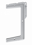
Expansion bracket kit, including an expansion bracket, two pairs of screw anchors and screws, and two locking screws
|
1kit, optional |
ES4200-4T1MS-B ES4200-4T2RMS-B ES4200-4P2RMS-B ES4200-8P2RX |
|
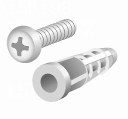
Screw anchor and screw
|
2 pairs, provided |
ES4200-4T2ST ES4200-8T2ST ES4200-4P2ST ES4200-8P2ST ES4200-8T2RS ES4200-8P2RS ES4200-8T2S ES4200-16T2RX ES4200-4P2RS ES4200-4P2RST ES4200-8P2S |
|
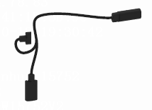
1-to-2 Type-C USB power cord
|
1, provided |
ES4200-2T1S-M |

2 Installing the switch
|
|
CAUTION: Keep the tamper-proof seal on a mounting screw on the chassis cover intact, and if you want to open the chassis, contact H3C for permission. Otherwise, H3C shall not be liable for any consequence. |
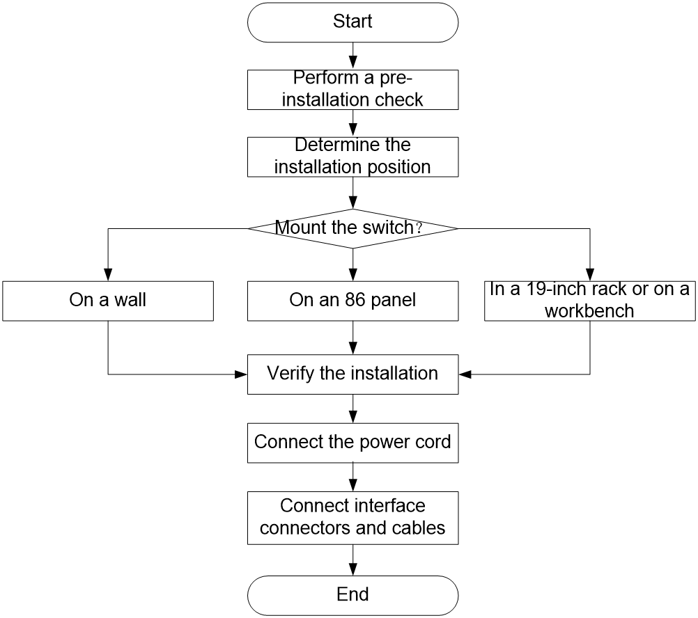
Figure2-1 Installation flowchart
Installation methods
Table2-2 Installation methods
|
Installation method |
Switch model |
Restrictions and guidelines |
Installation procedure |
|
Mounting the switch on a wall |
ES4200-4T2ST ES4200-8T2ST ES4200-4P2ST ES4200-8P2ST ES4200-8T2RS ES4200-8P2RS ES4200-8T2S ES4200-8P2S ES4200-4P2RS ES4200-4P2RST ES4200-16T2RX |
N/A |
|
|
Mounting the switch on an 86 panel |
ES4200-2T1S-M ES4200-4T1MS-B ES4200-4T2RMS-B ES4200-4P2RMS-B ES4200-8P2RX-B |
The ES4200-4T1MS-B, ES4200-4T2RMS-B, or ES4200-4P2RMS-B switch can work alone or in conjunction with the ES4200-2T1S-M switch to provide two or three networks in one switch. The ES4200-2T1S-M switch must be installed on another switch model as an expansion module. It cannot work alone. Do not install the ES4200-2T1S-M expansion module in the front of the ES4200-8P2RX-B switch. |
|
|
Mounting the switch in a 19-inch rack by using front mounting brackets |
ES4200-16P2RX-B ES4200-16P2RS |
N/A |
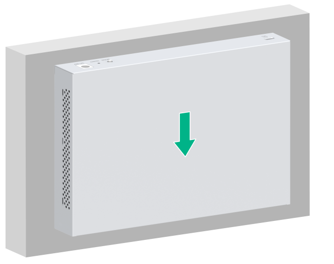
Mounting the switch on a wall
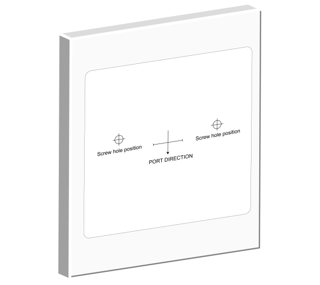
1. Affix the installation positioning sticker horizontally to the wall with the arrow on it facing downwards.
Figure2-2 Installation positioning sticker
2. Drill two holes with a diameter of 6 mm (0.24 in) and a depth of 35 mm (1.38 in) at the screw hole locations on the positioning sticker, and then remove the positioning sticker.
Figure2-3 Drilling holes on the wall

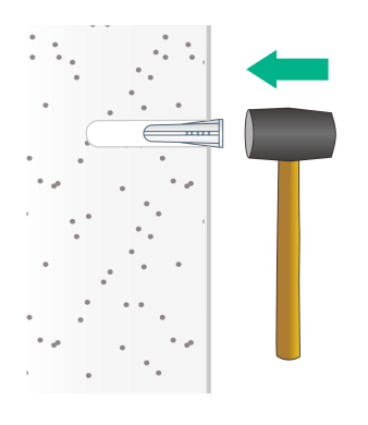
3. Insert a screw anchor into each hole, and tap the screw anchor with a rubber hammer until it is all flush with the wall surface.
Figure2-4 Securing the screw anchors
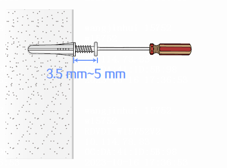
4. Fasten a screw into each screw anchor. Leave 3.5 to 5 mm (0.14 to 0.20 in) between the screw head and the wall for hanging the switch.
Figure2-5 Fastening a screw into a screw anchor
5. Align the installation holes in the switch with the screws on the wall. Make sure the port side faces downwards. Hang the switch on the screws and slide the switch down until the screws seat securely in the installation holes.
Figure2-6 Wall-mounting the switch (1)
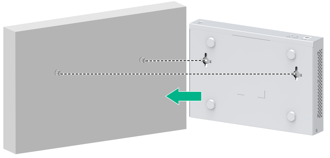
Figure2-7 Wall-mounting the switch (2)
Mounting the switch on an 86 panel
Prerequisites
· Plan the networks and route the cables in advance.
· The switch models that can work alone support both local power supply (using a power adapter) and PoE power supply (using a terminal block). When you use local power supply, arrange the network cables in the 86 panel in advance. When you use PoE power supply, calculate the power consumption of the power source device and power supply distance in advance. Arrange a hybrid copper-fiber cable in the 86 panel and complete pigtail connection.
· Only the ES4200-2T1S-M supports power supply through a Type-C USB power cord. Please prepare a 1-to-2 Type-C USB power cord in advance.
· To use one switch to provide three networks, purchase an expansion bracket.
Mounting the switch on an 86 panel (single switch)
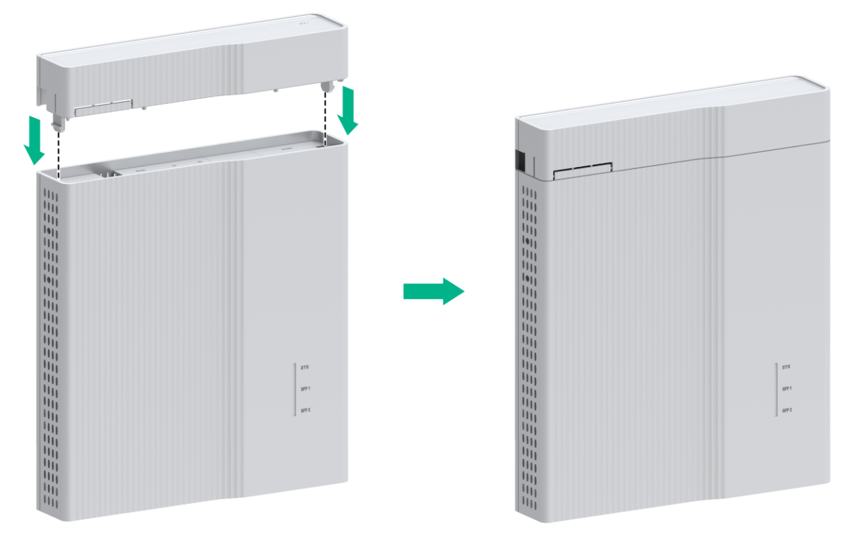
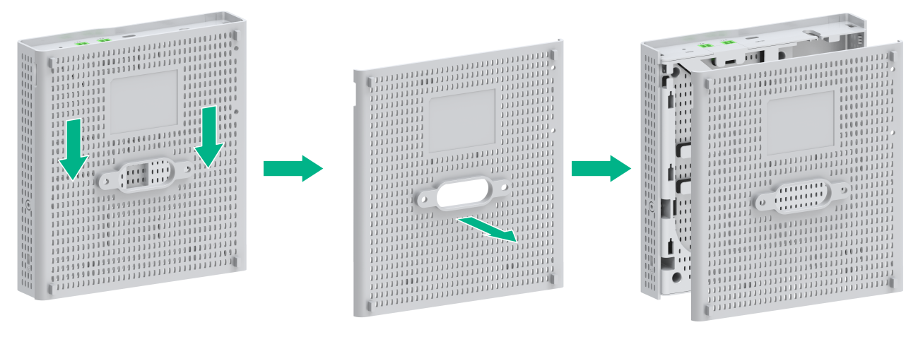
1. Press the clips on both sides of the dust cover with both hands to remove the dust cover.
Figure2-8 Removing the dust cover
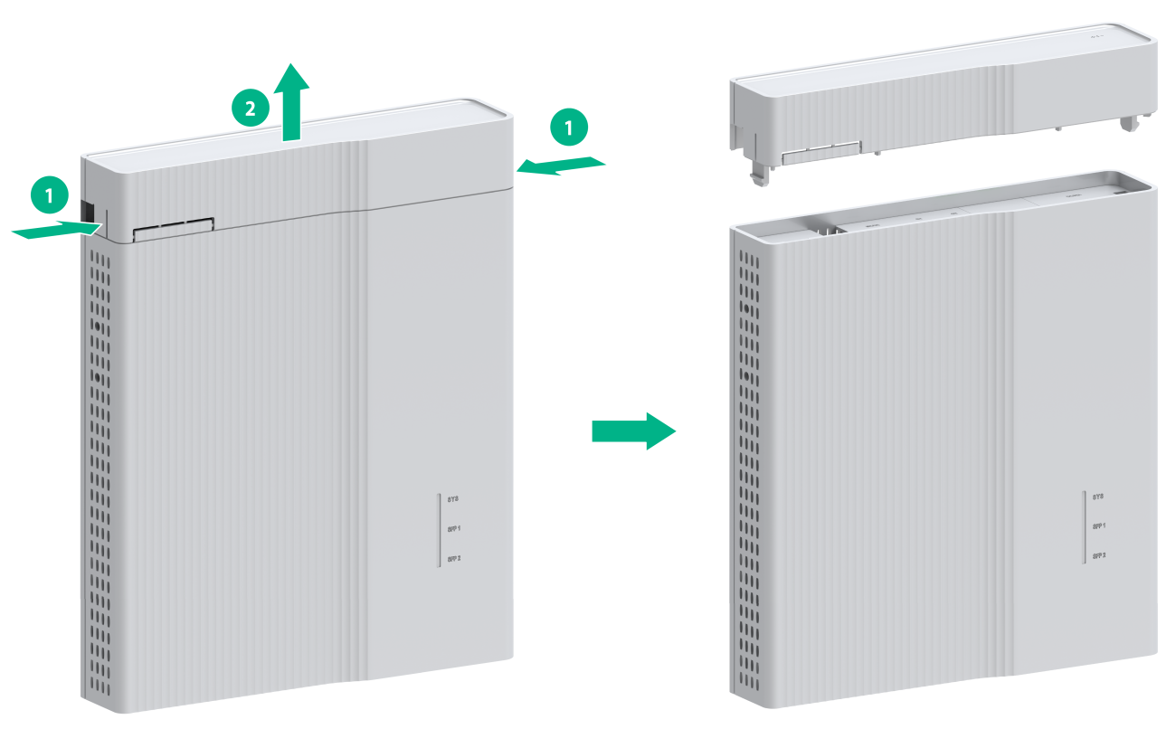
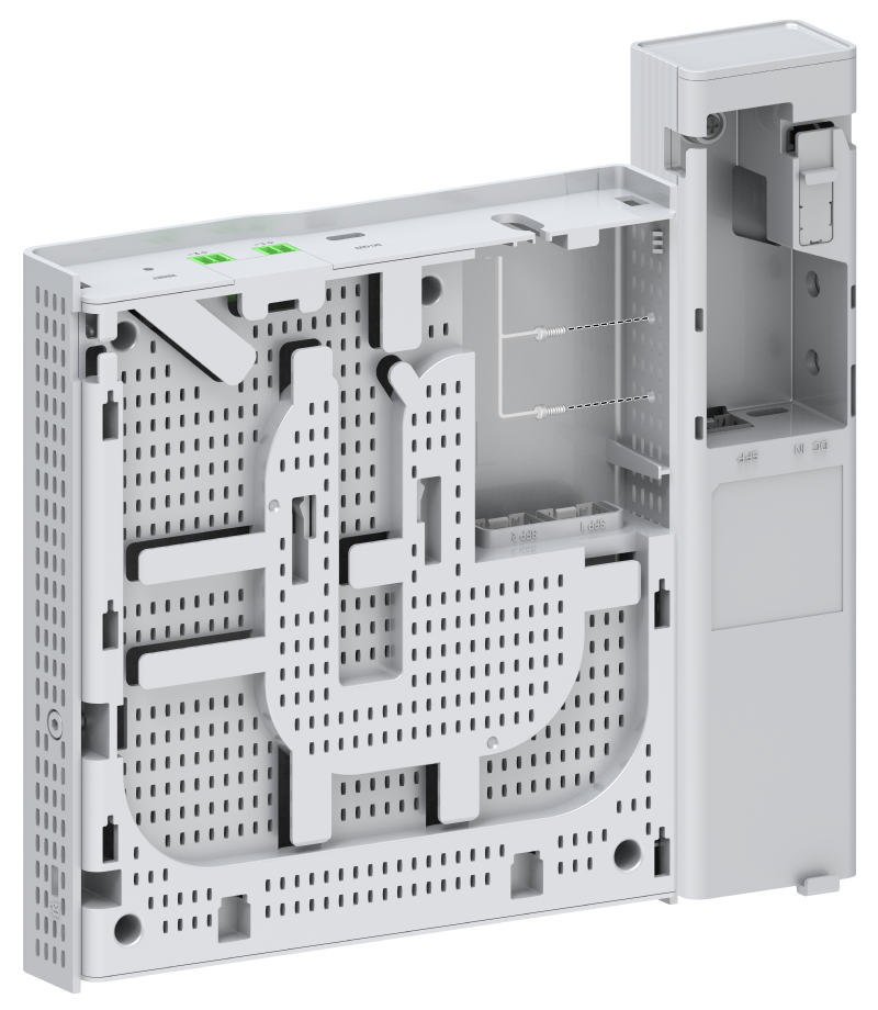
2. Orient the switch so that you face the rear panel of the switch and the port side faces downwards. Gently pull down the rear cover to remove it.
Figure2-9 Removing the rear cover

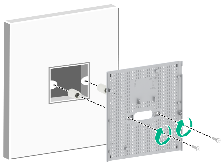
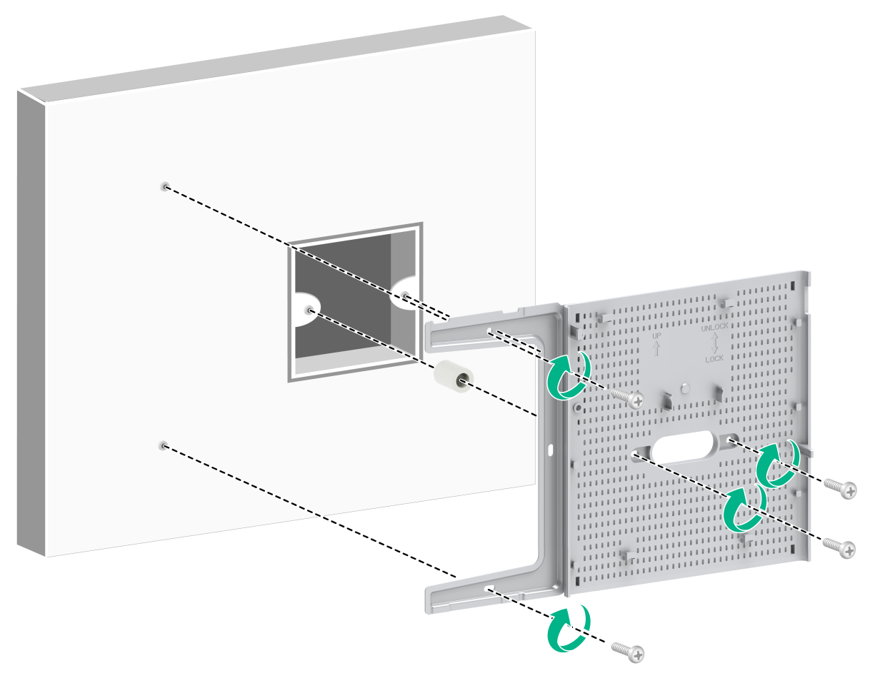
3. Attach the rear cover to the 86 panel and use round-head screws to secure the rear cover.
|
|
CAUTION: · To prevent the rear cover from damage or deformation, do not use excessive force when you attach it to the 86 panel. · Before you attach the rear cover to the 86 panel, thread the pre-arranged hybrid copper-fiber cable or fiber in the 86 panel through the oval hole in the rear cover. · If the distance between the round-head screw hole in the 86 box and the wall is in the range of 3 to 13 mm (0.12 to 0.51 in), add stops by using plastic studs. This prevents the round-head screws from being screwed too deeply and avoids rear cover deformation. If the distance is less than 3 mm (0.12 in), do not use plastic studs. · As a best practice, use an electric screwdriver to fasten the round-head screws. The recommended torque is approximately 1.6 Nm (14.16 lb.in). Fasten the round-head screws until the four supports on the rear cover engage the wall and make sure the rear cover is parallel with the wall. |
Figure2-10 Attaching the rear cover to the 86 panel

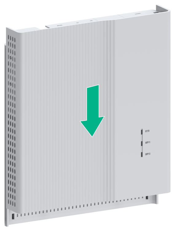
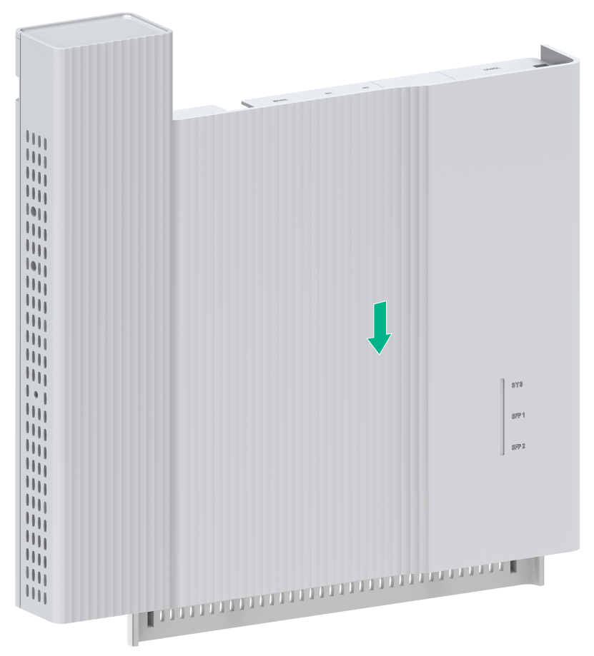
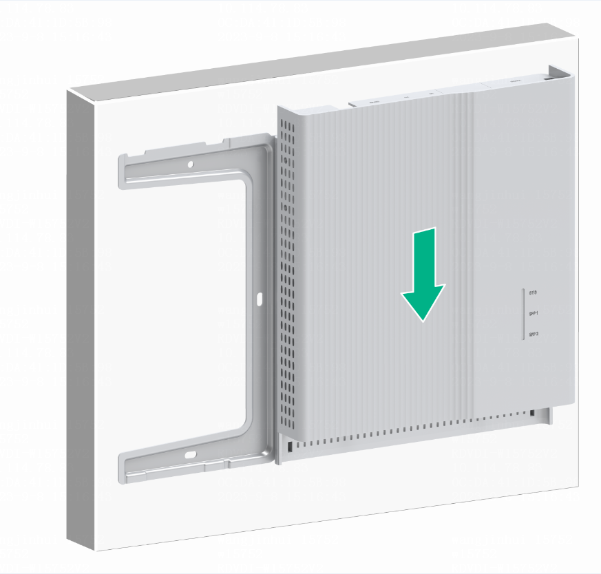
4. Mount the chassis. Position the pegs on the rear cover into the keyhole slots in the chassis and then slide the chassis down until the rear cover sits securely in the keyhole slots, as shown in Figure2-11 and Figure2-12.
|
|
NOTE: · When you use PoE power supply, complete connecting the power cord and fiber before you mount the chassis. For more information, see "Connecting cables to uplink port" and "Connecting the power cord." · When you use local power supply, complete connecting the fiber before you mount the chassis. For more information, see "Connecting cables to uplink port." |
Figure2-11 Mounting the chassis (1)

Figure2-12 Mounting the chassis (2)
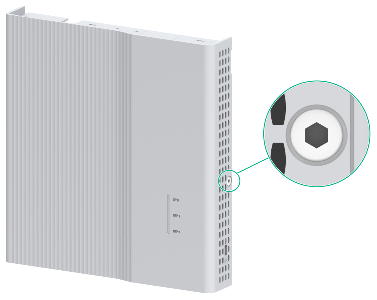
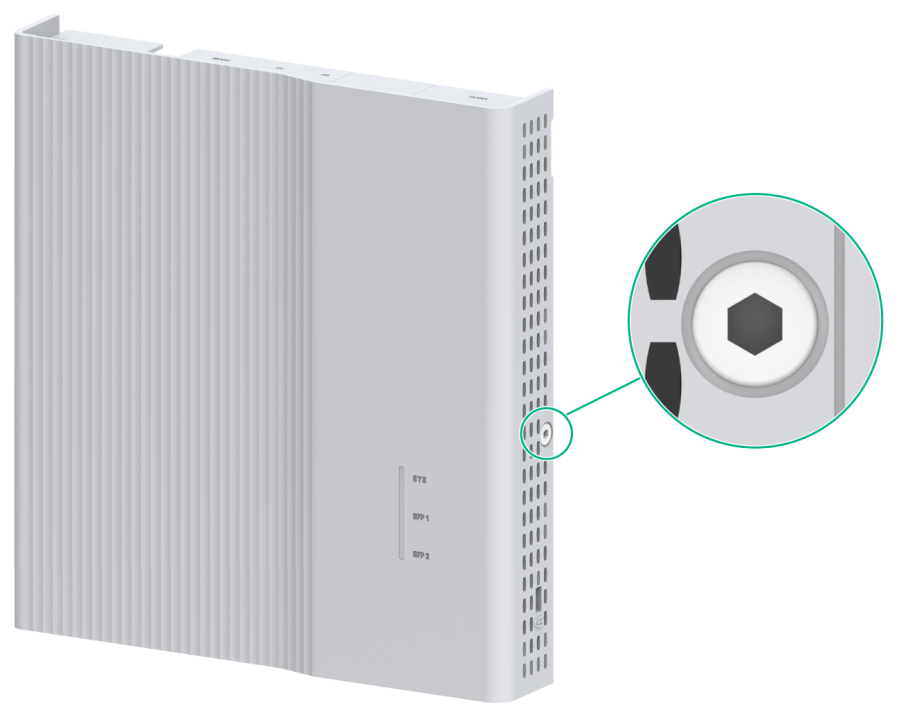
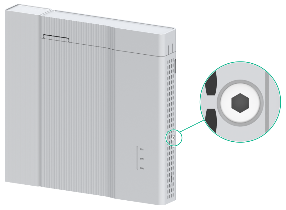
5. Fasten the locking screw by using an Allen wrench to secure the chassis to the rear cover.
Figure2-13 Fastening the locking screw
6. Install the dust cover.
Figure2-14 Installing the dust cover
Mounting the switch on an 86 panel (dual networks in one switch)
This installation method installs an ES4200-2T1S-M expansion module on a switch to provide two networks.
The ES4200-2T1S-M expansion module supports the following installation methods:
· Method 1: Install the ES4200-2T1S-M in the front of the chassis. For the installation procedure, see "Method 1."
· Method 1: Install the ES4200-2T1S-M on the side of the chassis. For the installation procedure, see "Method 2."
The ES4200-8P2RX-B switch does not support method 1.
Method 1
1. Press the clips on both sides of the dust cover with both hands to remove the dust cover.
Figure2-15 Removing the dust cover

2. Orient the switch so that you face the rear panel of the switch and the port side faces downwards. Gently pull down the rear cover to remove it.
Figure2-16 Removing the rear cover

3. Attach the rear cover to the 86 panel and use round-head screws to secure the rear cover.
|
|
CAUTION: · To prevent the rear cover from damage or deformation, do not use excessive force when you attach it to the 86 panel. · Before you attach the rear cover to the 86 panel, thread the pre-arranged hybrid copper-fiber cable or fiber in the 86 panel through the oval hole in the rear cover. · If the distance between the round-head screw hole in the 86 box and the wall is in the range of 3 to 13 mm (0.12 to 0.51 in), add stops by using plastic studs. This prevents the round-head screws from being screwed too deeply and avoids rear cover deformation. If the distance is less than 3 mm (0.12 in), do not use plastic studs. · As a best practice, use an electric screwdriver to fasten the round-head screws. The recommended torque is approximately 1.6 Nm (14.16 lb.in). Fasten the round-head screws until the four supports on the rear cover engage the wall and make sure the rear cover is parallel with the wall. |
Figure2-17 Attaching the rear cover to the 86 panel
4. Mount the chassis. Position the pegs on the rear cover into the keyhole slots in the chassis and then slide the chassis down until the rear cover sits securely in the keyhole slots, as shown in Figure2-18 and Figure2-19.
|
|
NOTE: · When you use PoE power supply, complete connecting the power cord and fiber before you mount the chassis. For more information, see "Connecting cables to uplink port" and "Connecting the power cord." · When you use local power supply, complete connecting the fiber before you mount the chassis. For more information, see "Connecting cables to uplink port." |
Figure2-18 Mounting the chassis (1)
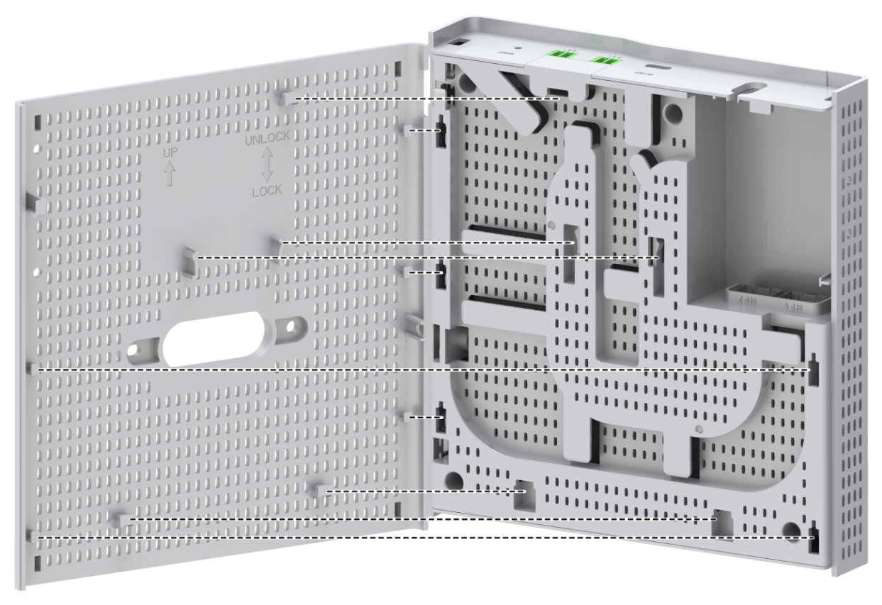
Figure2-19 Mounting the chassis (2)

5. Fasten the locking screw by using an Allen wrench to secure the chassis to the rear cover.
Figure2-20 Fastening the locking screw
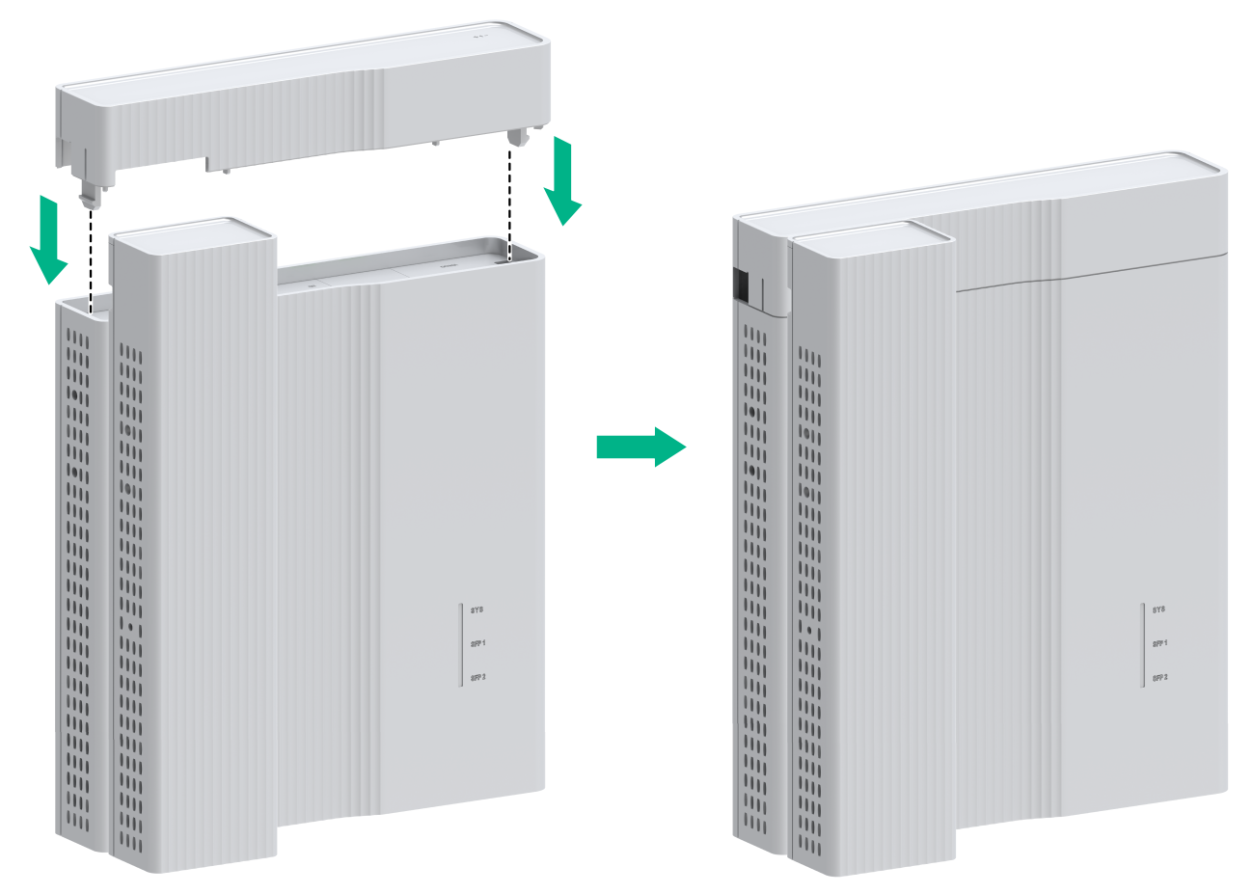
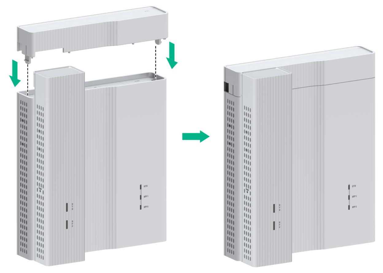
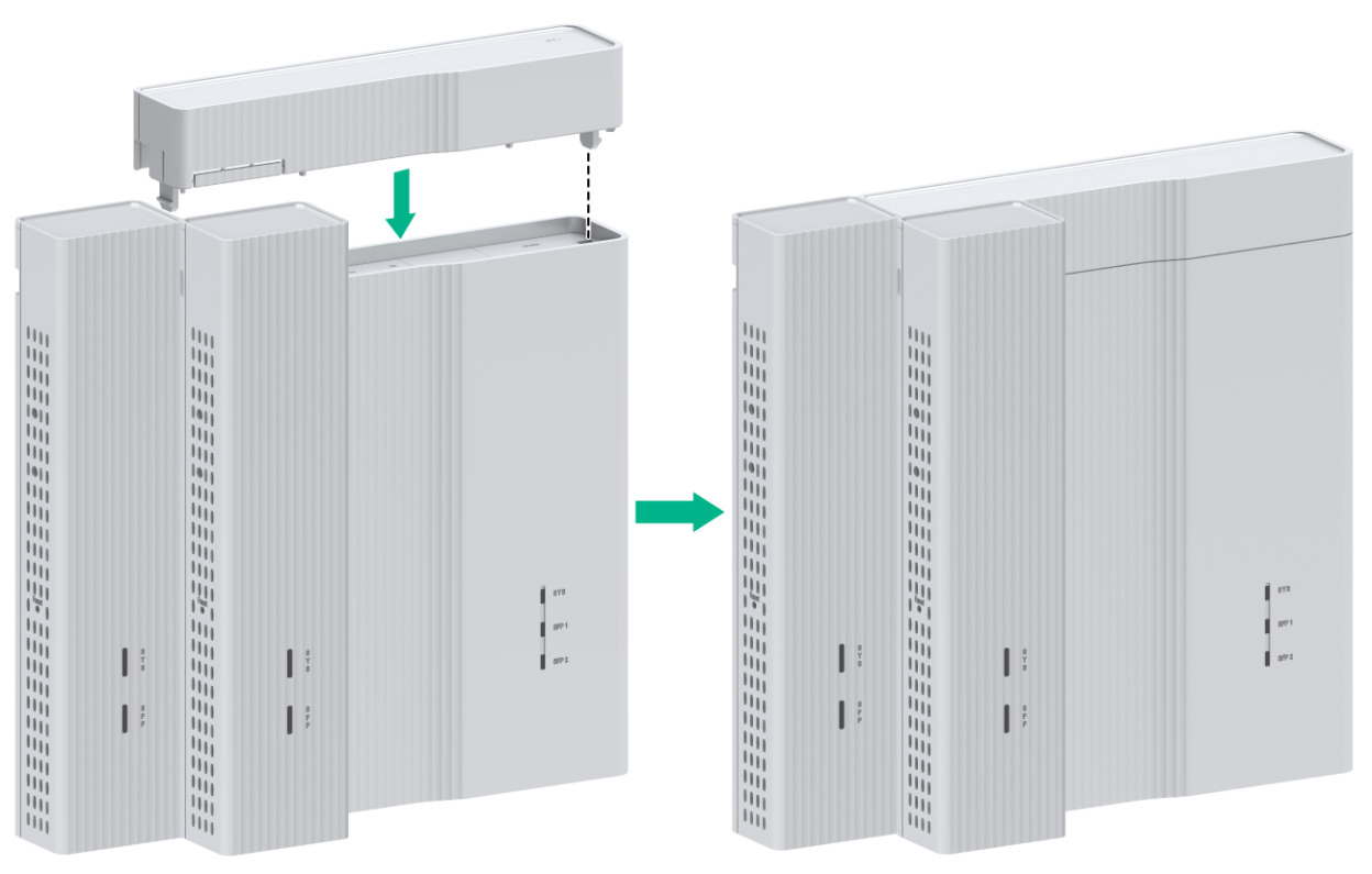
6. Install the expansion module on the chassis. Position the expansion module so that the upper clip on it compresses against the upper edge of the chassis. Gently pull down the expansion module until the lower clip on it compresses against the lower edge of the chassis. Align the left panels of the expansion module and the chassis.
Figure2-21 Installing the expansion module
7. Install the dust cover, as shown in Figure2-22 and Figure2-23.
Figure2-22 Installing the dust cover (1)
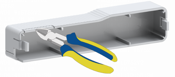
Figure2-23 Installing the dust cover (2)
Method 2
1. Press the clips on both sides of the dust cover with both hands to remove the dust cover.
Figure2-24 Removing the dust cover

2. Orient the switch so that you face the rear panel of the switch and the port side faces downwards. Gently pull down the rear cover to remove it.
Figure2-25 Removing the rear cover
3. Use the provided round-head screws to attach the rear cover to the 86 panel.
|
|
CAUTION: · To prevent the rear cover from damage or deformation, do not use excessive force when you attach it to the 86 panel. · Before you attach the rear cover to the 86 panel, thread the pre-arranged hybrid copper-fiber cable or fiber in the 86 panel through the oval hole in the rear cover. · If the distance between the round-head screw hole in the 86 box and the wall is in the range of 3 to 13 mm (0.12 to 0.51 in), add stops by using plastic studs. This prevents the round-head screws from being screwed too deeply and avoids rear cover deformation. If the distance is less than 3 mm (0.12 in), do not use plastic studs. · As a best practice, use an electric screwdriver to fasten the round-head screws. The recommended torque is approximately 1.6 Nm (14.16 lb.in). Fasten the round-head screws until the four supports on the rear cover engage the wall and make sure the rear cover is parallel with the wall. |
Figure2-26 Attaching the rear cover to the 86 panel

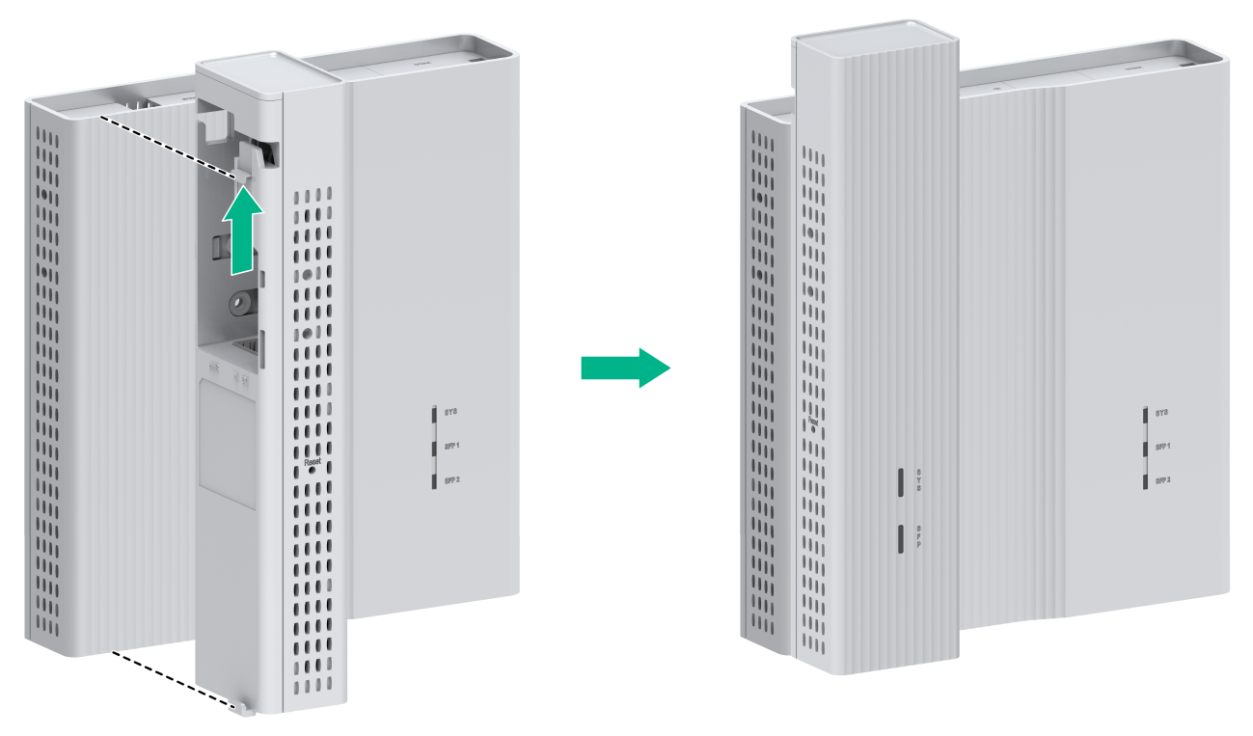
4. Install the expansion module on the chassis. Facing the rear panel of the switch, place the chassis and expansion module side by side, as shown in Figure2-27. Then, fasten the locking screws by using an Allen wrench (user supplied) to secure the expansion module to the chassis.
|
|
NOTE: The expansion module can only be powered by the switch through a 1-to-2 Type-C USB power cord. As a best practice, connect the 1-to-2 Type-C USB power cord when you install the expansion module. For more information, see "Connecting a USB power cord (USB power supply)." |
Figure2-27 Installing the expansion module on the chassis
5. Mount the chassis. Position the pegs on the rear cover into the keyhole slots in the chassis and then slide the chassis down until the rear cover sits securely in the keyhole slots, as shown in Figure2-28 and Figure2-29.
|
|
NOTE: · When you use PoE power supply, complete connecting the power cord and fiber before you mount the chassis. For more information, see "Connecting cables to uplink port" and "Connecting the power cord." · When you use local power supply, complete connecting the fiber before you mount the chassis. For more information, see "Connecting cables to uplink port." |
Figure2-28 Mounting the chassis (1)
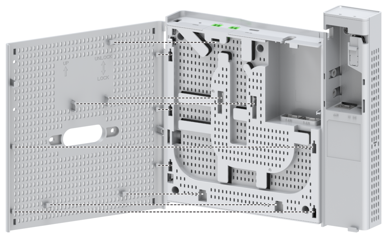
Figure2-29 Mounting the chassis (2)
6. Install the dust cover.
Figure2-30 Installing the dust cover
7. Fasten the locking screw by using an Allen wrench to secure the chassis to the rear cover.
Figure2-31 Fastening the locking screw
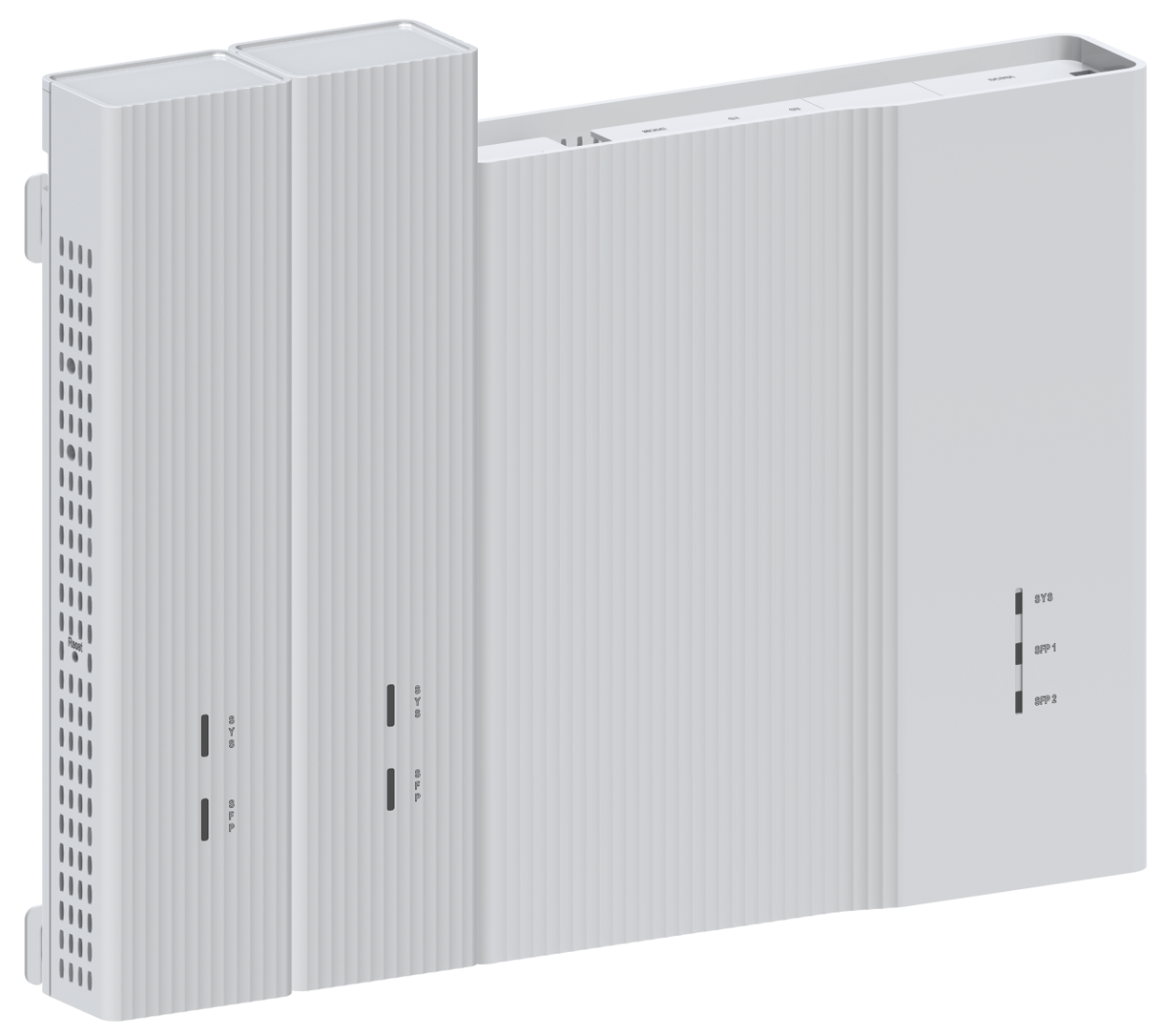
Mounting the switch on an 86 panel (three networks in one switch)
This installation method installs two ES4200-2T1S-M expansion modules on a switch to provide three networks.
The ES4200-2T1S-M expansion modules support the following installation methods:
· Method 1: Install the expansion modules on the expansion bracket secured to the chassis. For the installation procedure, see "Method 1."
· Method 2: Install the expansion modules on the front and side panels of the chassis. For the installation procedure, see "Method 2."
The ES4200-8P2RX-B does not support method 2.
Method 1
1. Press the clips on both sides of the dust cover with both hands to remove the dust cover.
Figure2-32 Removing the dust cover

2. Orient the switch so that you face the rear panel of the switch and the port side faces downwards. Gently pull down the rear cover to remove it.
Figure2-33 Removing the rear cover

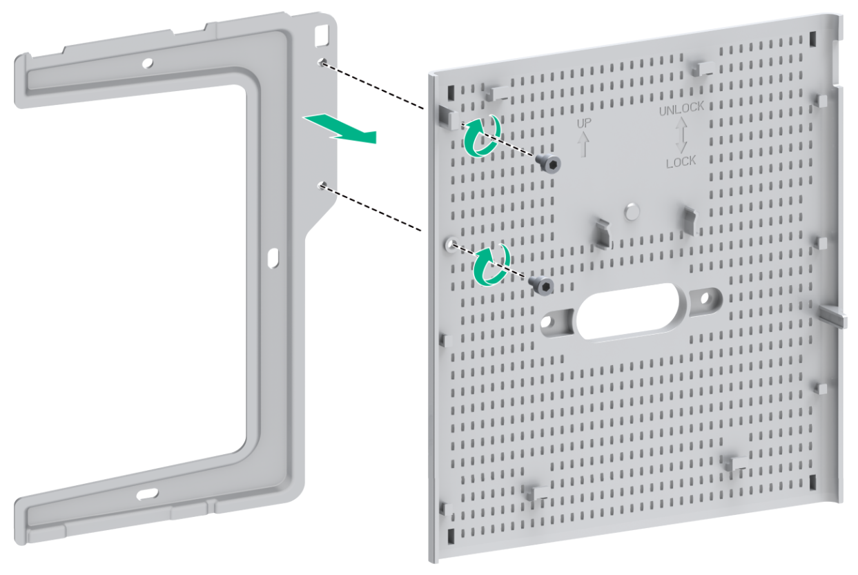
3. Attach the expansion bracket to the switch rear cover
Figure2-34 Attaching the expansion bracket to the switch rear cover
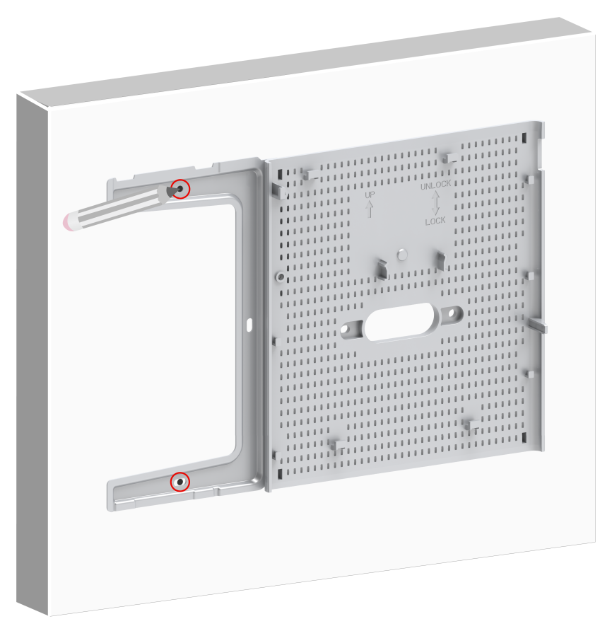
4. Mark the expansion bracket installation holes on the wall, as shown in Figure2-35.
Figure2-35 Marking the expansion bracket installation holes
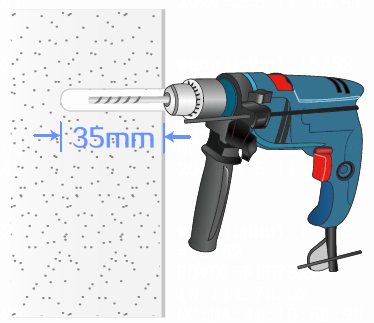
5. Drill two holes with a diameter of 6 mm (0.24 in) and a depth of 35 mm (1.38 in) at the marked locations.
Figure2-36 Drilling holes on the wall
6. Insert a screw anchor into each hole, and tap the screw anchor with a rubber hammer until it is all flush with the wall surface.
Figure2-37 Securing the screw anchors

7. Use the provided round-head screws to attach the rear cover to the 86 panel. Use screws to attach the expansion bracket to the wall.
|
|
CAUTION: · To prevent the rear cover from damage or deformation, do not use excessive force when you attach it to the 86 panel. · Before you attach the rear cover to the 86 panel, thread the pre-arranged hybrid copper-fiber cable or fiber in the 86 panel through the oval hole in the rear cover. · If the distance between the round-head screw hole in the 86 box and the wall is in the range of 3 to 13 mm (0.12 to 0.51 in), add stops by using plastic studs. This prevents the round-head screws from being screwed too deeply and avoids rear cover deformation. If the distance is less than 3 mm (0.12 in), do not use plastic studs. · As a best practice, use an electric screwdriver to fasten the round-head screws. The recommended torque is approximately 1.6 Nm (14.16 lb.in). Fasten the round-head screws until the four supports on the rear cover engage the wall and make sure the rear cover is parallel with the wall. |
Figure2-38 Attaching the rear cover to the 86 panel and the expansion bracket to the wall
8. Mount the chassis. Position the pegs on the rear cover into the keyhole slots in the chassis and then slide the chassis down until the rear cover sits securely in the keyhole slots, as shown in Figure2-39 and Figure2-40.
|
|
NOTE: · When you use PoE power supply, complete connecting the power cord and fiber before you mount the chassis. For more information, see "Connecting cables to uplink port" and "Connecting the power cord." · When you use local power supply, complete connecting the fiber before you mount the chassis. For more information, see "Connecting cables to uplink port." |
Figure2-39 Mounting the chassis (1)
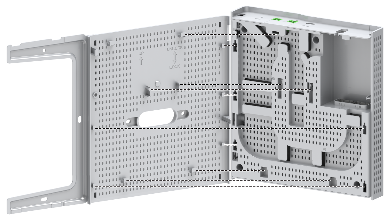
Figure2-40 Mounting the chassis (2)
9. Fasten the locking screw by using an Allen wrench to secure the chassis to the rear cover.
Figure2-41 Fastening the locking screw

10. Install the expansion modules on the chassis. Position an expansion module so that the upper clip on it compresses against an upper notch of the expansion bracket. Gently pull down the expansion module until the lower clip on it compresses against the corresponding lower notch of the expansion bracket. Install the other expansion module in the same way. See Figure2-42 and Figure2-43.
|
|
NOTE: The expansion module can only be powered by the switch through a 1-to-2 Type-C USB power cord. As a best practice, connect the 1-to-2 Type-C USB power cord when you install the expansion module. For more information, see "Connecting a USB power cord (USB power supply)." |
Figure2-42 Installing expansion modules (1)
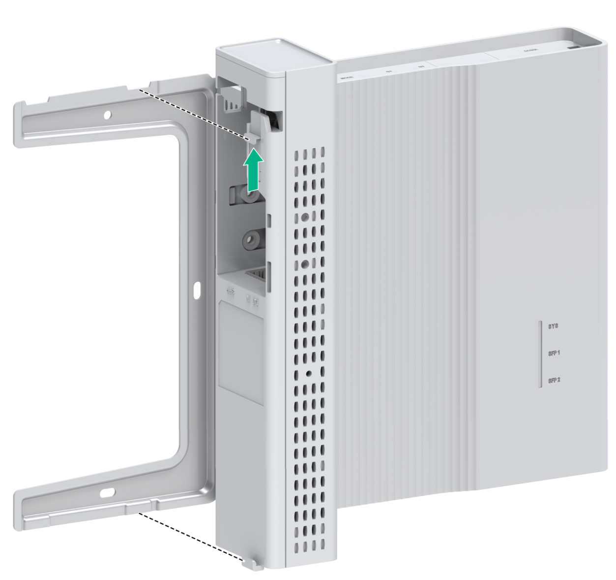
Figure2-43 Installing expansion modules (2)
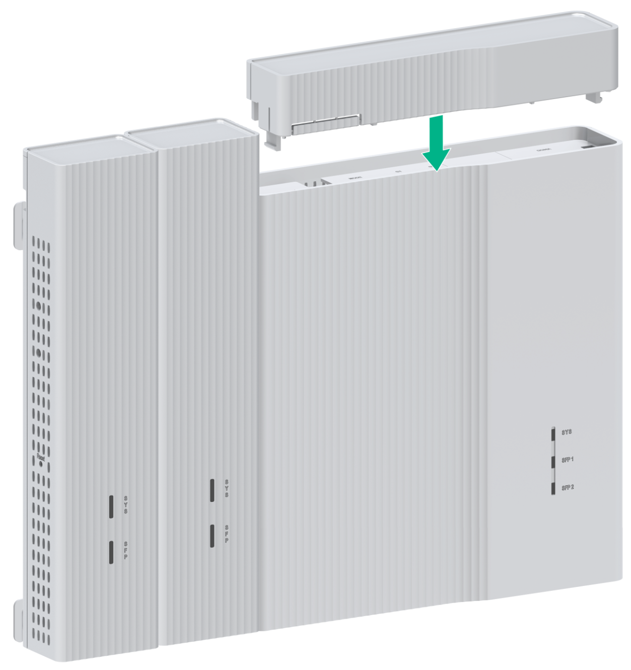
11. Install the dust cover.
Figure2-44 Installing the dust cover
Method 2
1. Press the clips on both sides of the dust cover with both hands to remove the dust cover.
Figure2-45 Removing the dust cover

2. Orient the switch so that you face the rear panel of the switch and the port side faces downwards. Gently pull down the rear cover to remove it.
Figure2-46 Removing the rear cover

3. Install an expansion module on the chassis.
Facing the rear panel of the switch, place the chassis and the expansion module side by side, as shown in Figure2-47. Then, fasten the locking screws by using an Allen wrench (user supplied) to secure the expansion module to the chassis.
|
|
NOTE: The expansion module can only be powered by the switch through a 1-to-2 Type-C USB power cord. As a best practice, connect the 1-to-2 Type-C USB power cord when you install the expansion module. For more information, see "Connecting a USB power cord (USB power supply)." |
Figure2-47 Installing an expansion module on the chassis

4. Mount the chassis. Position the pegs on the rear cover into the keyhole slots in the chassis and then slide the chassis down until the rear cover sits securely in the keyhole slots, as shown in Figure2-48 and Figure2-49.
|
|
NOTE: · When you use PoE power supply, complete connecting the power cord and fiber before you mount the chassis. For more information, see "Connecting cables to uplink port" and "Connecting the power cord." · When you use local power supply, complete connecting the fiber before you mount the chassis. For more information, see "Connecting cables to uplink port." |
Figure2-48 Mounting the chassis (1)
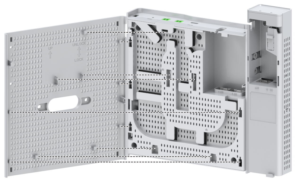
Figure2-49 Mounting the chassis (2)

5. Fasten the locking screw by using an Allen wrench to secure the chassis to the rear cover.
Figure2-50 Fastening the locking screw

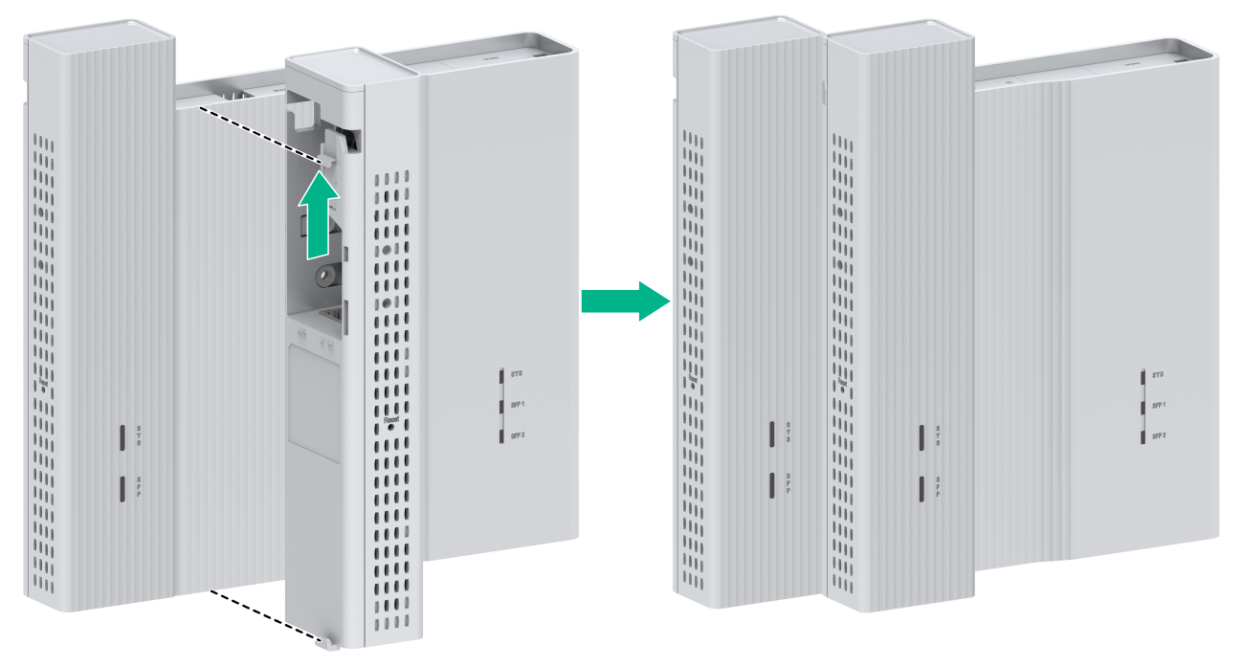
6. Install the other expansion module on the chassis. Position the expansion module so that the upper clip on it compresses against the upper edge of the chassis. Gently pull down the expansion module until the lower clip on it compresses against the lower edge of the chassis. Align the left panels of the expansion module and the chassis.
|
|
NOTE: The expansion module can only be powered by the switch through a 1-to-2 Type-C USB power cord. As a best practice, connect the 1-to-2 Type-C USB power cord when you install the expansion module. For more information, see "Connecting a USB power cord (USB power supply)." |
Figure2-51 Installing expansion modules
7. Install the dust cover, as shown in Figure2-52 and Figure2-53.
Figure2-52 Installing the dust cover (1)

Figure2-53 Installing the dust cover (2)
Mounting the switch in a 19-inch rack
Attaching the front mounting brackets to the switch
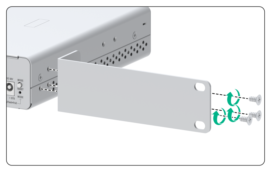
1. Place the narrow flange of the mounting bracket against the chassis side panel. Align the mounting bracket installation holes with the screw holes in the chassis.
2. Fasten the M4 screws (provided) to secure the mounting bracket to the switch.
3. Attach the front mounting bracket to the other side of the chassis in the same way.
Figure2-54 Attaching a front mounting bracket to the chassis
Mounting the switch in a rack
1. Wear an ESD wrist strap and make sure it makes good skin contact and is reliably grounded.
2. Verify that the front mounting brackets have been securely attached to the switch chassis. See "Attaching the front mounting brackets to the switch."
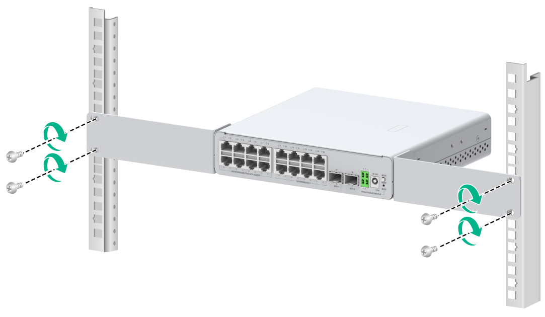
3. One person supports the bottom of the switch, and moves the switch to an appropriate position based on the installation positions of the front mounting brackets.
4. The other person uses user-supplied M6 screws and cage nuts (with surfaces treated for corrosion protection) to attach the mounting brackets to the rack and verifies that the brackets are level and secure.
Figure2-55 Rack-mounting the switch
Mounting the switch on a workbench
|
|
IMPORTANT: · Only the ES4200-4T2ST, ES4200-8T2ST, ES4200-4P2ST, ES4200-8P2ST, ES4200-8T2RS, ES4200-8P2RS, ES4200-16P2RX-B, ES4200-4P2RS, ES4200-4P2RST, ES4200-16T2RX, ES4200-16P2RS, ES4200-8T2S, and ES4200-8P2S switches support workbench mounting. · Ensure 10 cm (3.94 in) of clearance around the chassis for heat dissipation. · Do not place heavy objects on the switch. |
To mount the switch on a workbench:
1. Verify that the workbench is sturdy and reliably grounded.
2. Place the switch with bottom up, and clean the round holes in the chassis bottom with dry cloth.
3. (Applicable to only the ES4200-16P2RX-B and ES4200-16P2RS switches.) Attach the rubber feet to the four round holes in the chassis bottom.
4. Place the switch with upside up on the workbench.
3 Connecting cables to uplink ports
The uplink ports mentioned in this section typically connect to the uplink network, but are not exclusively used for that purpose.
To connect uplink ports, you can use common fibers, copper cables, or fibers in a hybrid copper-fiber cable. The connection method is the same for the cables. The following example connects common fibers to an uplink port on the switch.
To connect common fibers to an uplink port on the switch:
1. Install a transceiver module.
Close the bail latch upward to catch the knob on the top of the transceiver module. Grasp the transceiver module between your thumb and index finger and correctly orient it. Align it with the fiber port and push it gently into the port until you feel it snaps into place. See Figure3-2.
Transceiver modules and fiber ports have disorientation rejection designs. If you cannot insert a transceiver module easily into a port, the orientation might be wrong. Remove and reorient the transceiver module.
Figure3-2 Installing a transceiver module
2. Connect the fibers.
(Skip this step when a copper cable is used.) Grasping the fiber connector between your thumb and index finger, align it with the transceiver module optical bore and push it into the bore. Transceiver module optical bores and fiber connectors have disorientation rejection designs. If you cannot insert a fiber connector easily into a transceiver module optical bore, the orientation might be wrong. Remove and reorient the connector.
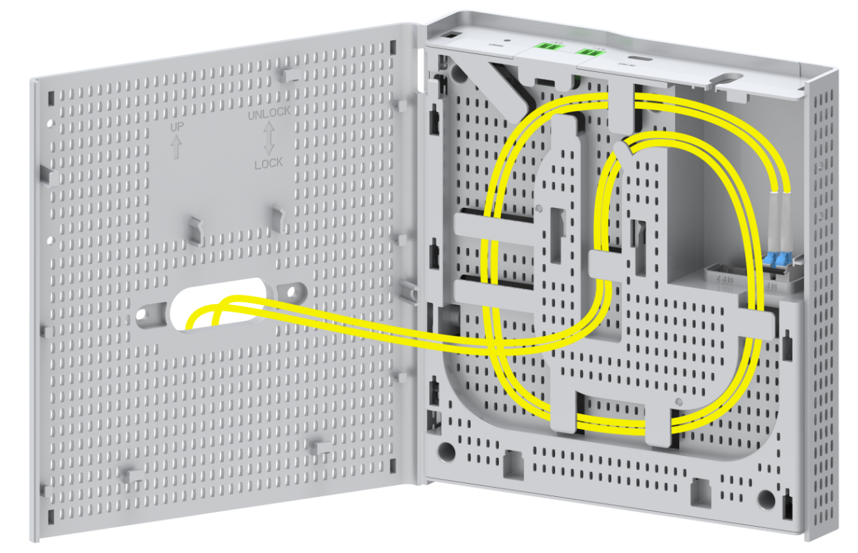
3. Coil the cable.
After you connect the fiber connectors or copper cable, fit the fibers or copper cable into the cabling channel at the chassis rear in counterclockwise direction.
4 Connecting the power cord
|
|
CAUTION: · Provide a circuit breaker for each power cord. · Before connecting the power cord, make sure the circuit breaker on the power cord is turned off. |
Table4-1 displays the power supply methods supported by the switch.
Table4-1 Power supply methods supported by the switch
|
Power supply method |
Switch model |
Power cord connection procedure |
|
Local power supply (using a power adapter) |
ES4200-4T2ST ES4200-8T2ST ES4200-4T1MS-B ES4200-4T2RMS-B ES4200-8T2RS ES4200-4P2ST ES4200-8P2ST ES4200-8P2RS ES4200-4P2RMS-B ES4200-8T2S ES4200-8P2S ES4200-4P2RS ES4200-4P2RST ES4200-16T2RX ES4200-16P2RS |
|
|
PoE power supply (using a terminal block) |
ES4200-4T2RMS-B ES4200-4P2RMS-B ES4200-4P2RS ES4200-4P2RST ES4200-8T2RS ES4200-8P2RS ES4200-16T2RX ES4200-16P2RS |
Connecting the power cord by using a terminal block (PoE power supply)_Ref146444329 |
|
USB power supply |
ES4200-2T1S-M |
|
|
Ethernet cable power supply |
ES4200-4P2RST |
Inserting the Ethernet cable that connects to the powering source switch into the power input port on the switch |
Connecting a power adapter (local power supply)
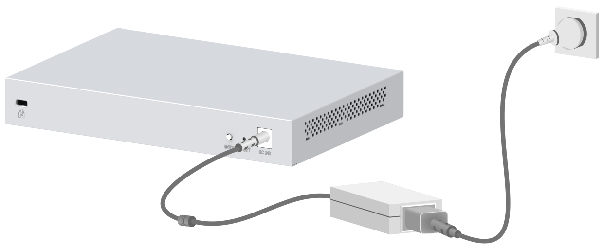
The switch supports the following types of power adapters. The supported power adapter varies by switch model.
· Type-1 power adapter: A type-1 power adapter can meet the power supply requirements.
· Type-2 power adapter: A type-2 power adapter must be connected to an AC power cord to supply power.
To connecting a power adapter:
1. Connect the power adapter to an AC power cord. (This step is only applicable to a type-2 power adapter.)
2. Insert the circular plug of the power adapter into the power adapter receptacle on the switch.
3. Connect the other end of the power adapter to an external AC power source.
Figure4-1 Connecting a type-1 power adapter
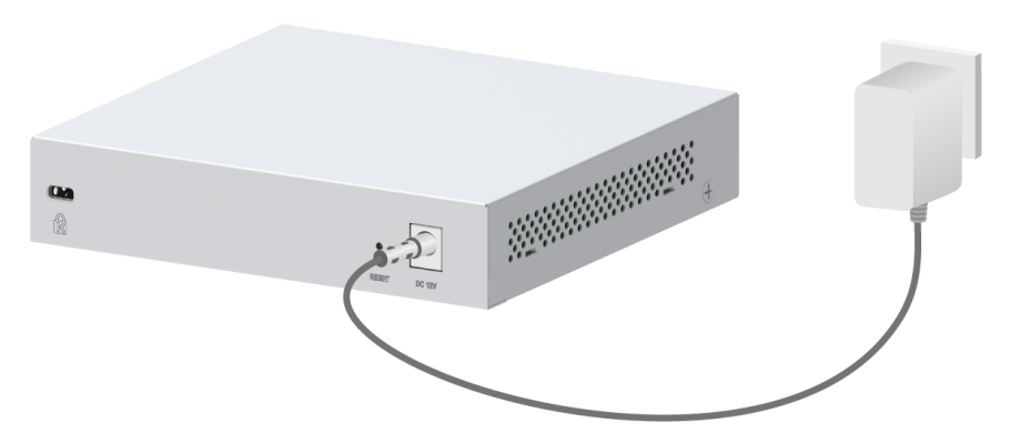
Figure4-2 Connecting a type-2 power adapter
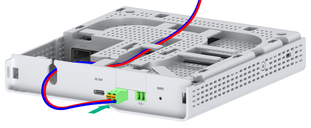
Connecting the power cord by using a terminal block (PoE power supply)
1. Remove the outer rubber sheath from the ends of the positive and negative power wires in the hybrid copper-fiber cable.
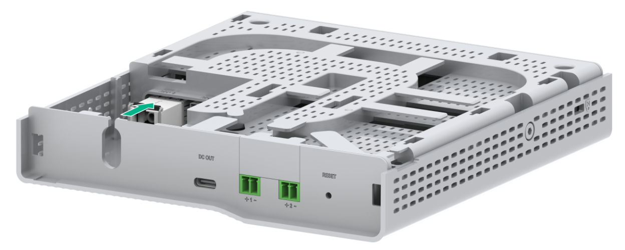
2. Use a flat-head screwdriver to press down the yellow button on the terminal block, and then insert the power wire ends into the terminal block. See Figure4-3.
3. Connect the terminal block to the PoE in port on the switch. See Figure4-4.
Figure4-3 Connecting the power wires by using a terminal block (1)
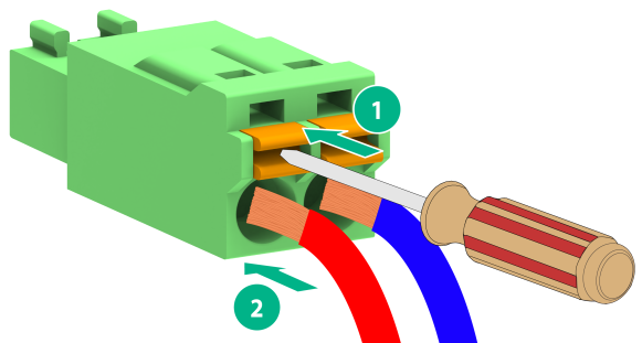
Figure4-4 Connecting the power wires by using a terminal block (2)
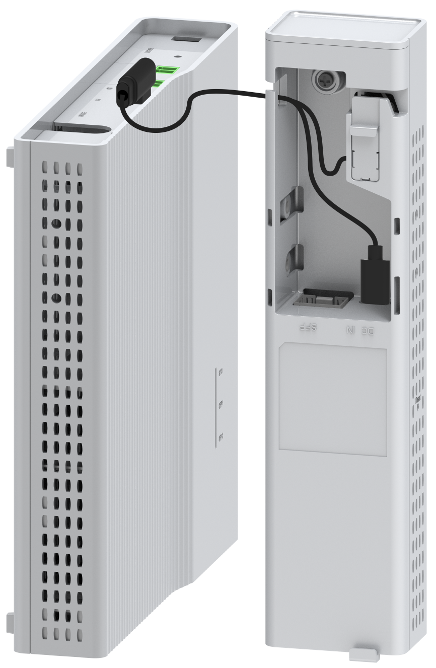
Connecting a USB power cord (USB power supply)
1. Insert the end of the 1-to-2 Type-C USB power cord that has one connector into the Type-C USB port on the switch, as shown in Figure4-5 and Figure4-6.
Figure4-5 Connecting a USB power cord to the switch that integrates two networks (method 1)
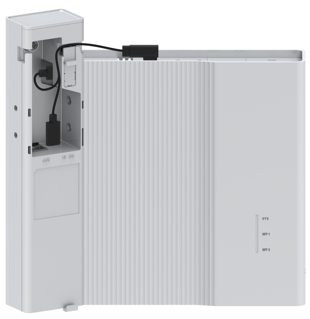
Figure4-6 Connecting a USB power cord to the switch that integrates two networks (method 2)
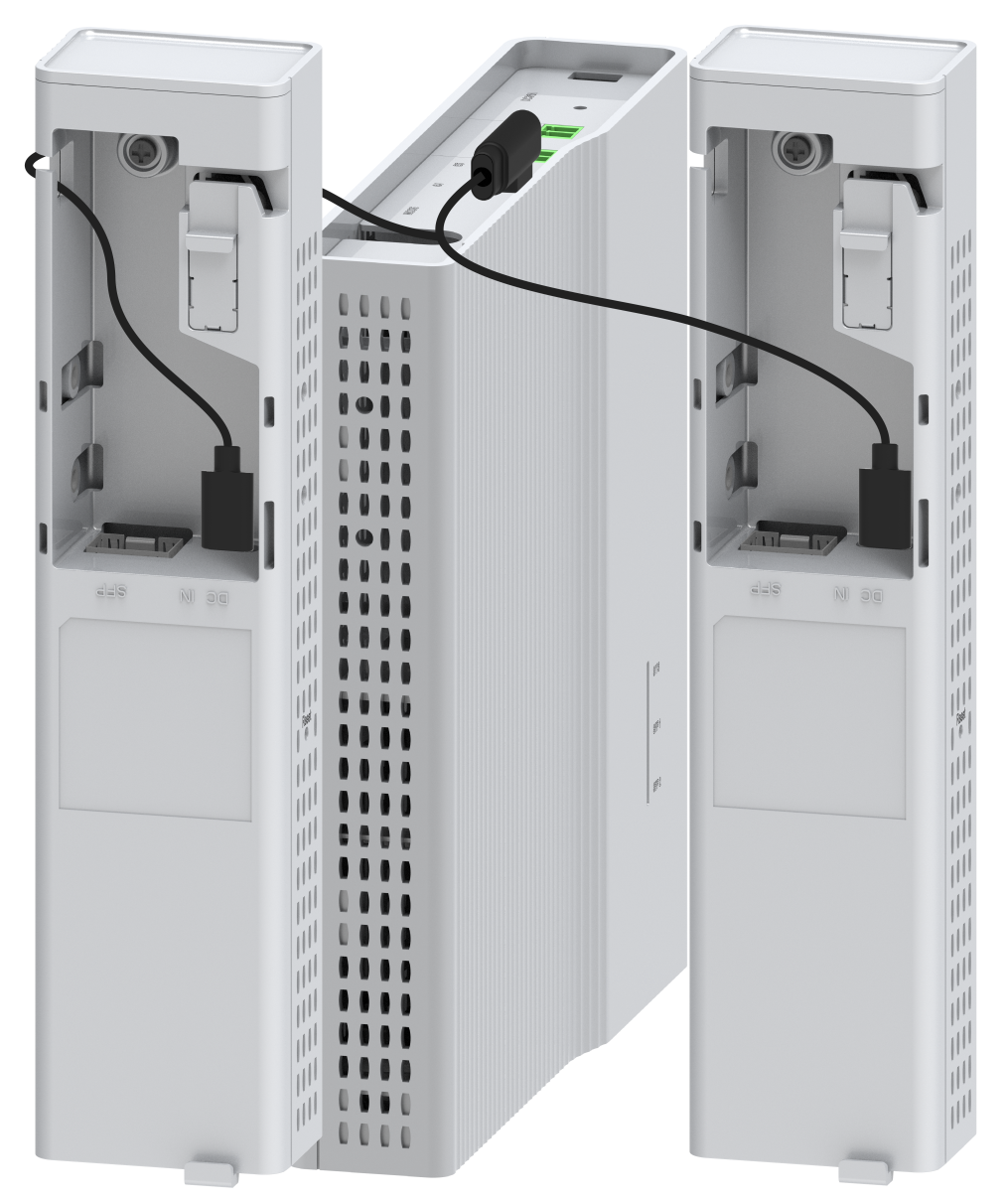
2. Insert the end of the 1-to-2 Type-C USB power cord that has two connectors into the Type-C USB ports on the expansion module, as shown in Figure4-7 and Figure4-8.
Figure4-7 Connecting a USB power cord to the switch that integrates three networks (method 1)
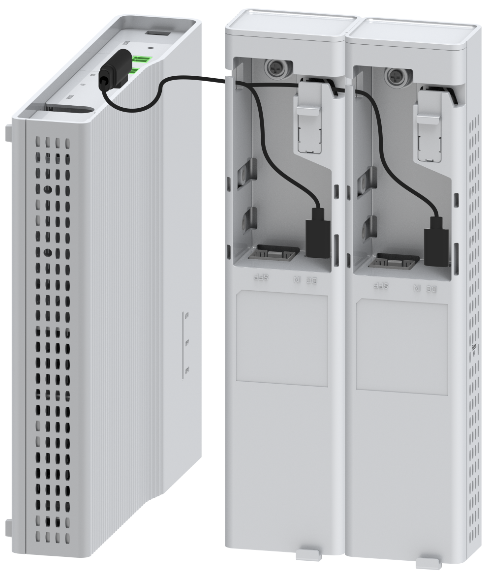
Figure4-8 Connecting a USB power cord to the switch that integrates three networks (method 2)
5 Verifying the installation
After you complete the installation, verify the following information:
· There is enough space around the switch for heat dissipation.
· The rack or workbench is stable.
· The grounding cable is connected correctly.
· The power source is as required by the switch.
· The power cords are correctly connected.
· If part of the network cable for a port is routed outdoors, verify that a network port lightning protector is used for the port. If a power line is routed from outdoors, verify that a surge protected power strip is used for the switch.
