- Table of Contents
-
- 08-Local forwarding
- 01-Local Forwarding Mode and Local Portal Authentication Configuration Examples
- 02-Local Forwarding Mode Direct Portal Authentication Configuration Examples
- 03-Local Forwarding Mode Direct Portal Authentication (IPv6) Configuration Examples
- 04-Local Forwarding Configuration Examples
- 05-Wired Port Local Forwarding through Wireless Terminator Configuration Examples
- 06-Remote AP Configuration Examples
- 07-Downlink VLAN Management for Fit-Mode APs Configuration Examples
- 08-Downlink VLAN Management for Fit-Mode APs and Cloud-Mode APs Configuration Examples
- Related Documents
-
| Title | Size | Download |
|---|---|---|
| 07-Downlink VLAN Management for Fit-Mode APs Configuration Examples | 107.31 KB |
|
|
|
H3C Access Controllers |
|
Downlink VLAN Management for Fit-Mode APs |
|
Configuration Examples |
Copyright © 2024 New H3C Technologies Co., Ltd. All rights reserved.
No part of this manual may be reproduced or transmitted in any form or by any means without prior written consent of New H3C Technologies Co., Ltd.
Except for the trademarks of New H3C Technologies Co., Ltd., any trademarks that may be mentioned in this document are the property of their respective owners.
The information in this document is subject to change without notice.
Introduction
The following information provides a downlink VLAN management configuration example for fit-mode APs.
Prerequisites
The following information applies to Comware-based access controllers and access points. Procedures and information in the examples might be slightly different depending on the software or hardware version of the access controllers and access points.
The configuration examples in this document were created and verified in a lab environment, and all the devices were started with the factory default configuration. When you are working on a live network, make sure you understand the potential impact of every command on your network.
This document assumes that you have basic knowledge of AP management, radio management, WLAN access, VLAN, and local forwarding.
Example: Configuring downlink VLAN management for fit-mode APs
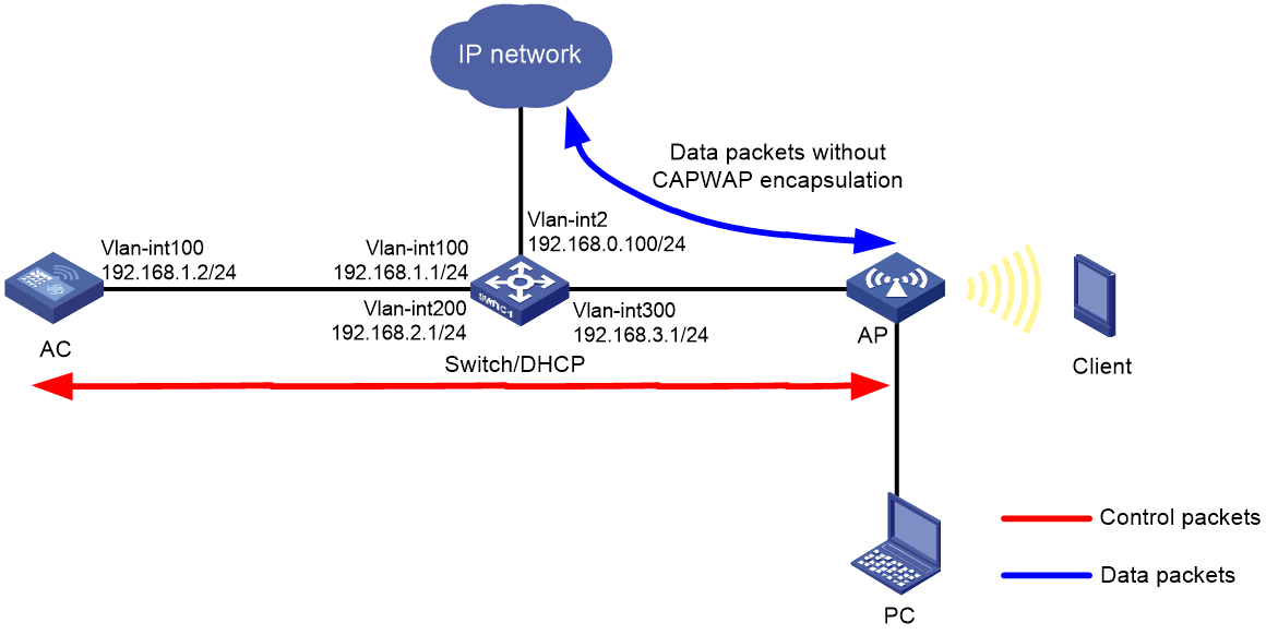
Network configuration
As shown in Figure 1, the switch acts as the DHCP server to assign IP addresses to the AP, the client, and the PC. The AP and the AC use VLAN 100 to establish a CAPWAP tunnel, the client uses VLAN 200 to access the wireless network, and the PC uses VLAN 300 to access the wired network.
· Configure local forwarding on the AC for the AP to directly forward client traffic.
· Connect the PC to a downlink Ethernet interface on the AP and make sure the PC can visit the external network.
Analysis
For the configuration to be deployed to the AP, configure remote configuration synchronization or deploy the map file.
Restrictions and guidelines
· For configuration to be deployed correctly, do not attach Tab characters or spaces to the end of command lines in the map file.
· Use the actual AP model and serial ID to configure the AP.
· If a backup AC is configured, make sure the backup AC is also uploaded with the map file.
Procedures
Configuring the AC
1. Configure the interfaces of the AC:
# Create VLAN 100 and VLAN-interface 100, and assign an IP address to the interface. The AC will use this IP address to establish a CAPWAP tunnel with the AP.
<AC> system-view
[AC] vlan 100
[AC-vlan100] quit
[AC] interface vlan-interface 100
[AC-Vlan-interface100] ip address 192.168.1.2 24
[AC-Vlan-interface100] quit
# Configure GigabitEthernet 1/0/1 that connects the AC to the switch as a trunk port, and assign the port to VLAN 100.
[AC] interface gigabitethernet 1/0/1
[AC-GigabitEthernet1/0/1] port link-type trunk
[AC-GigabitEthernet1/0/1] port trunk permit vlan 100
[AC-GigabitEthernet1/0/1] quit
2. Configure a wireless service:
# Create service template 1 and enter its view.
[AC] wlan service-template 1
# Set the SSID to service.
[AC-wlan-st-1] ssid service
# Set the VLAN to VLAN 200.
[AC-wlan-st-1] vlan 200
# Specify PSK as the AKM mode and specify 12345678 as the plaintext key.
[AC-wlan-st-1] akm mode psk
[AC-wlan-st-1] preshared-key pass-phrase simple 12345678
# Specify CCMP as the cipher suite and specify RSN as the security IE.
[AC-wlan-st-1] cipher-suite ccmp
[AC-wlan-st-1] security-ie rsn
# Configure the AP to forward client data traffic.
[AC-wlan-st-1] client forwarding-location ap
# Enable the service template.
[AC-wlan-st-1] service-template enable
[AC-wlan-st-1] quit
3. Configure AP settings:
|
|
NOTE: To simply AP configuration on a large-scale network, configure AP settings on a per AP group basis as a best practice. |
# Create manual AP ap1.
[AC] wlan ap ap1 model WA6320H
# Specify the AP serial ID.
[AC-wlan-ap-ap1] serial-id 219801A28N819CE0002T
[AC-wlan-ap-ap1] quit
# Create AP group group1 and configure ap1 as the AP grouping rule.
[AC] wlan ap-group group1
[AC-wlan-ap-group-group1] ap ap1
# Bind service template 1 to radio 2 for AP group group1.
[AC-wlan-ap-group-group1] ap-model WA6320H
[AC-wlan-ap-group-group1-ap-model-WA6320H] radio 2
[AC-wlan-ap-group-group1-ap-model-WA6320H-radio-2] service-template 1
# Enable radio 2.
[AC-wlan-ap-group-group1-ap-model-WA6320H-radio-2] radio enable
[AC-wlan-ap-group-group1-ap-model-WA6320H-radio-2] quit
[AC-wlan-ap-group-group1-ap-model-WA6320H] quit
4. To deploy configuration through remote configuration synchronization:
# Create VLANs 200 and 300 in AP group group1.
[AC-wlan-ap-group-group1] vlan 200
[AC-wlan-ap-group-group1-vlan200] quit
[AC-wlan-ap-group-group1] vlan 300
[AC-wlan-ap-group-group1-vlan300] quit
# Specify uplink Ethernet interface GE1/0/1 that connects the AP to the switch as a trunk port, assign the port to all VLANs, set the PVID to 1, and disable port isolation.
[AC-wlan-ap-group-group1] ap-model WA6320H
[AC-wlan-ap-group-group1-ap-model-WA6320H] gigabitethernet 1
[AC-wlan-ap-group-group1-ap-model-WA6320H-gigabitethernet-1] port-isolate disable
[AC-wlan-ap-group-group1-ap-model-WA6320H-gigabitethernet-1] port link-type trunk
[AC-wlan-ap-group-group1-ap-model-WA6320H-gigabitethernet-1] port trunk permit vlan all
[AC-wlan-ap-group-group1-ap-model-WA6320H-gigabitethernet-1] port trunk pvid vlan 1
[AC-wlan-ap-group-group1-ap-model-WA6320H-gigabitethernet-1] quit
# Specify all downlink Ethernet interfaces that connect the AP to the PC as access ports, assign the ports to VLAN 300, and disable port isolation. This step uses GE 1/0/2 as an example.
[AC-wlan-ap-group-group1-ap-model-WA6320H] gigabitethernet 2
[AC-wlan-ap-group-group1-ap-model-WA6320H-gigabitethernet-2] port-isolate disable
[AC-wlan-ap-group-group1-ap-model-WA6320H-gigabitethernet-2] port access vlan 300
[AC-wlan-ap-group-group1-ap-model-WA6320H-gigabitethernet-2] quit
[AC-wlan-ap-group-group1-ap-model-WA6320H] quit
# Enable remote configuration synchronization.
[AC-wlan-ap-group-group1] remote-configuration enable
# Synchronize the configuration to the AP.
[AC-wlan-ap-group-group1] remote-configuration synchronize
5. To deploy configuration through a map configuration file:
|
|
NOTE: · Use a text editor to edit the content of the apcfg.txt file in the configuration order, and upload the file to the AC. After the AP associates with the AC, use the map-configuration command to deploy the file to the AP for the configuration to take effect on the AP. · Specify all downlink Ethernet interfaces that connect the AP to the PC as access ports, assign the ports to VLAN 300, and disable port isolation. This step uses GE 1/0/2 as an example. |
# Edit the apcfg.txt file.
system-view
vlan 200
quit
vlan 300
quit
interface GigabitEthernet 1/0/1
undo port-isolate enable
port link-type trunk
port trunk permit vlan all
quit
interface GigabitEthernet 1/0/2
undo port-isolate enable
port access vlan 300
quit
# Specify the AP configuration file as apcfg.txt in the AP group's AP model view.
[AC] wlan ap-group group1
[AC-wlan-ap-group-group1] ap-model WA6320H
[AC-wlan-ap-group-group1-ap-model-WA6320H] map-configuration apcfg.txt
Configuring the switch
1. Configure switch interfaces:
# Create VLAN 2, VLAN 100, VLAN 200, VLAN 300, and the VLAN interfaces, and assign IP addresses to the VLAN interfaces. The switch will use VLAN 2 as the egress to the external network, VLAN 100 to forward packets between AC and AP, VLAN 200 to forward client traffic, and VLAN 300 for wired network access of the PC.
<Switch> system-view
[Switch] vlan 2
[Switch-vlan2] quit
[Switch] interface vlan-interface 2
[Switch-Vlan-interface2] ip address 192.168.0.100 24
[Switch-Vlan-interface2] quit
[Switch] vlan 100
[Switch-vlan100] quit
[Switch] interface vlan-interface 100
[Switch-Vlan-interface100] ip address 192.168.1.1 24
[Switch-Vlan-interface100] quit
[Switch] vlan 200
[Switch-vlan200] quit
[Switch] interface vlan-interface 200
[Switch-Vlan-interface200] ip address 192.168.2.1 24
[Switch-Vlan-interface200] quit
[Switch] vlan 300
[Switch-vlan300] quit
[Switch] interface vlan-interface 300
[Switch-Vlan-interface300] ip address 192.168.3.1 24
[Switch-Vlan-interface300] quit
# Specify GigabitEthernet 1/0/1 that connects the switch to the AC as a trunk port, and assign the port to VLAN 100.
[Switch] interface GigabitEthernet 1/0/1
[Switch-GigabitEthernet1/0/1] port link-type trunk
[Switch-GigabitEthernet1/0/1] port trunk permit vlan 100
[Switch-GigabitEthernet1/0/1] quit
# Specify GigabitEthernet 1/0/2 that connects the switch to the AP as a trunk port, assign the port to all VLANs, and set the PVID to 100.
[Switch] interface GigabitEthernet 1/0/2
[Switch-GigabitEthernet1/0/2] port link-type trunk
[Switch-GigabitEthernet1/0/2] port trunk permit vlan all
[Switch-GigabitEthernet1/0/2] port trunk pvid vlan 100
# Enable PoE on GigabitEthernet 1/0/2 that connects the switch to the AP.
[Switch-GigabitEthernet1/0/2] poe enable
[Switch-GigabitEthernet1/0/2] quit
# Specify GigabitEthernet 1/0/3 that connects the switch to the external network as an access port, and configure the port to permit traffic from VLAN 2.
[Switch] interface gigabitethernet 1/0/3
[Switch-GigabitEthernet1/0/3] port link-type access
[Switch-GigabitEthernet1/0/3] port access vlan 2
[Switch-GigabitEthernet1/0/3] quit
2. Configure DHCP:
# Enable DHCP.
[Switch] dhcp enable
# Create DHCP address pool vlan100 to assign an IP address to the AP, and specify subnet 192.168.1.0/24 in the DHCP address pool.
[Switch] dhcp server ip-pool vlan100
[Switch-dhcp-pool-vlan100] network 192.168.1.0 mask 255.255.255.0
[Switch-dhcp-pool-vlan100] forbidden-ip 192.168.1.2
[Switch-dhcp-pool-vlan100] gateway-list 192.168.1.1
[Switch-dhcp-pool-vlan100] quit
# Create DHCP address pool vlan200 to assign an IP address to the client, specify subnet 192.168.2.0/24 in the DHCP address pool, and specify the gateway address as 192.168.2.1. Set the DNS server address according to the actual networking planning.
[Switch] dhcp server ip-pool vlan200
[Switch-dhcp-pool-vlan200] network 192.168.2.0 mask 255.255.255.0
[Switch-dhcp-pool-vlan200] gateway-list 192.168.2.1
[Switch-dhcp-pool-vlan200] dns-list 192.168.2.1
[Switch-dhcp-pool-vlan200] quit
# Create DHCP address pool vlan300 to assign an IP address to the PC, specify subnet 192.168.3.0/24 in the DHCP address pool, and specify the gateway address as 192.168.3.1. Set the DNS server address according to the actual networking planning.
[Switch] dhcp server ip-pool vlan300
[Switch-dhcp-pool-vlan300] network 192.168.3.0 mask 255.255.255.0
[Switch-dhcp-pool-vlan300] gateway-list 192.168.3.1
[Switch-dhcp-pool-vlan300] dns-list 192.168.3.1
[Switch-dhcp-pool-vlan300] quit
3. Configure default routes for the switch to visit the external IP network. (Details not shown.)
Verifying the configuration
# Verify that the IP address of the client is 192.168.2.2, the IP address of the PC is 192.168.3.2, and both the client and the PC can visit the external network.
Configuration files
· AC:
#
Vlan 100
#
wlan service-template 1
ssid service
vlan 200
client forwarding-location ap
akm mode psk
preshared-key pass-phrase cipher $c$3$N//5BVbsOqdBTxi+7MJZKT6Zqh5MAmYs2ZzM
cipher-suite ccmp
security-ie rsn
service-template enable
#
interface Vlan-interface100
ip address 192.168.1.2 255.255.255.0
#
interface GigabitEthernet1/0/1
port link-type trunk
port trunk permit vlan 1 100
#
wlan ap-group group1
ap ap1
ap-model WA6320H
map-configuration flash:/apcfg.txt
radio 1
radio 2
radio enable
service-template 1
#
wlan ap ap1 model WA6320H
serial-id 219801A28N819CE0002T
#
· Switch:
#
dhcp enable
#
vlan 2
#
vlan 100
#
vlan 200
#
vlan 300
#
dhcp server ip-pool vlan100
gateway-list 192.168.1.1
network 192.168.1.0 mask 255.255.255.0
forbidden-ip 192.168.1.2
#
dhcp server ip-pool vlan200
gateway-list 192.168.2.1
network 192.168.2.0 mask 255.255.255.0
dns-list 192.168.2.1
#
dhcp server ip-pool vlan300
gateway-list 192.168.3.1
network 192.168.3.0 mask 255.255.255.0
dns-list 192.168.3.1
#
interface Vlan-interface2
ip address 192.168.0.100 255.255.255.0
#
interface Vlan-interface100
ip address 192.168.1.1 255.255.255.0
#
interface Vlan-interface200
ip address 192.168.2.1 255.255.255.0
#
interface Vlan-interface300
ip address 192.168.3.1 255.255.255.0
#
interface GigabitEthernet1/0/1
port link-mode bridge
port link-type trunk
port trunk permit vlan 1 100
#
interface GigabitEthernet1/0/2
port link-mode bridge
port link-type trunk
port trunk permit vlan all
port trunk pvid vlan 100
poe enable
#
interface GigabitEthernet1/0/3
port link-type access
port access vlan 2
#
Related documentation
· AP and WT Management Command Reference in H3C Access Controllers Command References
· AP and WT Management Configuration Guide in H3C Access Controllers Configuration Guides
· WLAN Access Command Reference in H3C Access Controllers Command References
· WLAN Access Configuration Guide in H3C Access Controllers Configuration Guides