- Table of Contents
- Related Documents
-
| Title | Size | Download |
|---|---|---|
| 02-Ethernet interface configuration | 128.90 KB |
Contents
Configuring Ethernet interfaces
Configuring common Ethernet interface settings
Configuring basic settings of an Ethernet interface
Configuring basic settings of an Ethernet subinterface
Configuring jumbo frame support
Configuring physical state change suppression on an Ethernet interface
Configuring dampening on an Ethernet interface
Setting the statistics polling interval
Enabling loopback testing on an Ethernet interface
Configuring interface alarm functions
Displaying the operating status and information of an interface
Shutting down all physical interfaces
Restoring the default settings for an interface
Configuring a Layer 3 Ethernet interface
Setting the MTU for an Ethernet interface or subinterface
Setting the MAC address of an Ethernet interface or subinterface
Display and maintenance commands for an Ethernet interface or subinterface
Configuring Ethernet interfaces
About Ethernet interface
Your device supports the following types of Ethernet interfaces:
· Layer 3 Ethernet interfaces—Physical Ethernet interfaces operating at the network layer (Layer 3) to route packets. You can assign an IP address to a Layer 3 Ethernet interface.
· Layer 3 Ethernet subinterfaces—Logical interfaces operating at the network layer. You can assign an IP address to a Layer 3 Ethernet subinterface. To enable a Layer 3 Ethernet interface to transport packets for multiple VLANs, you must create Layer 3 subinterfaces on the Layer 3 Ethernet interface. For information about how a Layer 3 Ethernet subinterface sends and receives VLAN-tagged packets, see Layer 2—LAN Switching Configuration Guide.
Configuring common Ethernet interface settings
Configuring basic settings of an Ethernet interface
About this task
You can configure an Ethernet interface to operate in one of the following duplex modes:
· Full-duplex mode—The interface can send and receive packets simultaneously.
· Autonegotiation mode—The interface negotiates a duplex mode with its peer.
You can set the speed of an Ethernet interface or enable it to automatically negotiate a speed with its peer.
Restrictions and guidelines
The shutdown and loopback commands are mutually exclusive.
When you configure the speed for a fixed SFP+ port in an RT-HRIC-XP8-H transceiver module, follow these restrictions and guidelines:
· If you install an SFP-GE-T or SFP-GE-T-D transceiver module on the fixed SFP+ port, you can set the speed of the port to 100 Mbps or 1000 Mbps.
· If you install other transceiver modules on the fixed SFP+ port, you can set the speed of the port to 1000 Mbps or 10000 Mbps.
Procedure
1. Enter system view.
system-view
2. Enter Ethernet interface view.
interface interface-type interface-number
3. Set the description for the Ethernet interface.
description text
The default setting is interface-name Interface. For example, Ten-GigabitEthernet2/0/0 Interface.
4. Set the duplex mode for the Ethernet interface.
duplex { auto | full }
By default, the duplex mode is auto for Ethernet interfaces.
5. Set the speed for the Ethernet interface.
speed { 100 | 1000 | 10000 | 25000 | 50000 | 100000 | auto }
By default, the speed is auto for an Ethernet interface.
6. Set the expected bandwidth for the Ethernet interface.
bandwidth bandwidth-value
By default, the expected bandwidth (in kbps) is the interface baud rate divided by 1000.
7. Bring up the Ethernet interface.
undo shutdown
By default, an Ethernet interface is up.
Configuring basic settings of an Ethernet subinterface
About this task
By default, a Layer 3 Ethernet subinterface processes packets for only the VLAN whose ID is the same as the subinterface number.
Restrictions and guidelines for Ethernet subinterface basic settings
To transmit and receive packets through an Ethernet subinterface, you must associate it with a VLAN. For more information, see Layer 2—LAN Switching Configuration Guide.
To transmit packets between a local Ethernet subinterface and a remote Ethernet subinterface, configure them with the same subinterface number and VLAN ID.
The shutdown command cannot be executed on an Ethernet interface in a loopback test.
Procedure
1. Enter system view.
system-view
2. Create an Ethernet subinterface.
interface interface-type interface-number.subnumber
3. Set the description for the Ethernet subinterface.
description text
The default setting is interface-name Interface. For example, Ten-GigabitEthernet2/0/0.1 Interface.
4. Set the expected bandwidth for the Ethernet subinterface.
bandwidth bandwidth-value
By default, the expected bandwidth (in kbps) is the interface baud rate divided by 1000.
5. Bring up the Ethernet subinterface.
undo shutdown
By default, an Ethernet subinterface is up.
Configuring jumbo frame support
About this task
Jumbo frames are frames larger than a fixed size and are typically received by an Ethernet interface during high-throughput data exchanges, such as file transfers.
The Ethernet interface processes jumbo frames in the following ways:
· When you configure the Ethernet interface to deny jumbo frames by using the undo jumboframe enable command, the Ethernet interface discards jumbo frames.
· When you configure the Ethernet interface with jumbo frame support, the Ethernet interface performs the following operations:
¡ Processes jumbo frames within the specified length.
¡ Discards jumbo frames that exceed the specified length.
Procedure
1. Enter system view.
system-view
2. Enter Ethernet interface view.
interface interface-type interface-number
3. Configure jumbo frame support.
jumboframe enable [ size ]
By default, the device allows jumbo frames within 10240 bytes to pass through.
Configuring physical state change suppression on an Ethernet interface
About this task
The physical link state of an Ethernet interface is either up or down. Each time the physical link of an interface comes up or goes down, the interface immediately reports the change to the CPU. The CPU then performs the following operations:
· Notifies the upper-layer protocol modules (such as routing and forwarding modules) of the change for guiding packet forwarding.
· Automatically generates traps and logs to inform users to take the correct actions.
To prevent frequent physical link flapping from affecting system performance, configure physical state change suppression. You can configure this feature to suppress only link-down events, only link-up events, or both. If an event of the specified type still exists when the suppression interval expires, the system reports the event to the CPU.
Restrictions and guidelines
You can configure different suppression intervals for link-up and link-down events.
If you execute the link-delay command multiple times on an interface, the following rules apply:
· You can configure the suppression intervals for link-up and link-down events separately.
· If you configure the suppression interval multiple times for link-up or link-down events, the most recent configuration takes effect.
Procedure
1. Enter system view.
system-view
2. Enter Ethernet interface view.
interface interface-type interface-number
3. Configure physical state change suppression.
link-delay { down | up } [ msec ] delay-time
By default, an interface immediately reports its physical state changes to the CPU.
Configuring dampening on an Ethernet interface
About this task
The interface dampening feature uses an exponential decay mechanism to prevent excessive interface flapping events from adversely affecting routing protocols and routing tables in the network. Suppressing interface state change events protects the system resources.
If an interface is not dampened, its state changes are reported. For each state change, the system also generates an SNMP trap and log message.
After a flapping interface is dampened, it does not report its state changes to the CPU. For state change events, the interface only generates SNMP trap and log messages.
Parameters
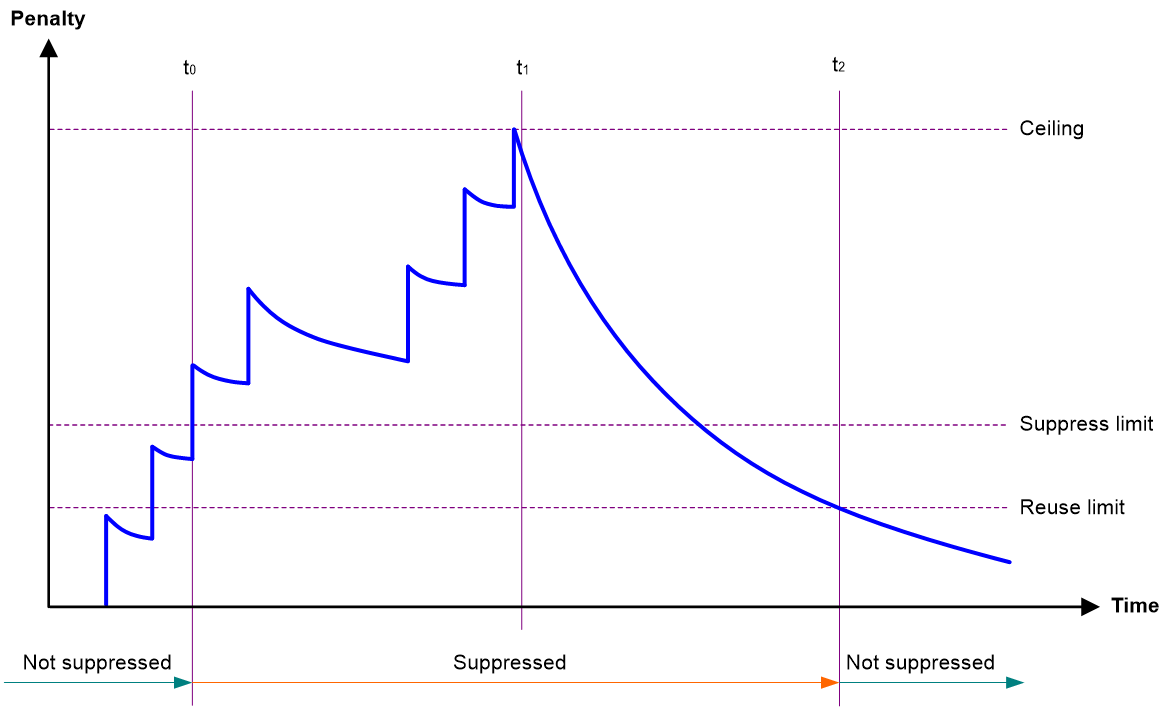
· Penalty—The interface has an initial penalty of 0. When the interface flaps, the penalty increases by 1000 for each down event until the ceiling is reached. It does not increase for up events. When the interface stops flapping, the penalty decreases by half each time the half-life timer expires until the penalty drops to the reuse threshold.
· Ceiling—The penalty stops increasing when it reaches the ceiling.
· Suppress-limit—The accumulated penalty that triggers the device to dampen the interface. In dampened state, the interface does not report its state changes to the CPU. For state change events, the interface only generates SNMP traps and log messages.
· Reuse-limit—When the accumulated penalty decreases to this reuse threshold, the interface is not dampened. Interface state changes are reported to the upper layers. For each state change, the system also generates an SNMP trap and log message.
· Decay—The amount of time (in seconds) after which a penalty is decreased.
· Max-suppress-time—The maximum amount of time the interface can be dampened. If the penalty is still higher than the reuse threshold when this timer expires, the penalty stops increasing for down events. The penalty starts to decrease until it drops below the reuse threshold.
When configuring the dampening command, follow these rules to set the values mentioned above:
· The ceiling is equal to 2(Max-suppress-time/Decay) × reuse-limit. It is not user configurable.
· The configured suppress limit is lower than or equal to the ceiling.
· The ceiling is lower than or equal to the maximum suppress limit supported.
Figure 1 shows the change rule of the penalty value. The lines t0 and t2 indicate the start time and end time of the suppression, respectively. The period from t0 to t2 indicates the suppression period, t0 to t1 indicates the max-suppress-time, and t1 to t2 indicates the complete decay period.
Figure 1 Change rule of the penalty value
Restrictions and guidelines
The dampening command does not take effect on the administratively down events. When you execute the shutdown command, the penalty restores to 0, and the interface reports the down event to the upper-layer protocols.
Procedure
1. Enter system view.
system-view
2. Enter Ethernet interface view.
interface interface-type interface-number
3. Enable dampening on the interface.
dampening [ half-life reuse suppress max-suppress-time ]
By default, interface dampening is disabled on Ethernet interfaces.
Setting the statistics polling interval
About this task
By setting the statistics polling interval, you can collect statistics of packets and analyze packets at the specified interval. Based on the interface traffic statistics, you can take traffic control measures promptly to avoid network congestion and service interruption.
· When network congestion is detected, you can set the statistics polling interval to be smaller than 300 seconds (30 seconds when congestion deteriorates). Then, check traffic distribution on interfaces within a short period of time. For data packets that cause congestion, take traffic control measures.
· When the network bandwidth is sufficient and services are operating normally, you can set the statistics polling interval to be greater than 300 seconds. Once traffic parameter anomalies occur, modify the statistics polling interval promptly so that you can observe the traffic parameter trend in real time.
To display the interface statistics collected in the last statistics polling interval, use the display interface command. To clear the interface statistics, use the reset counters interface command.
The statistics polling interval configured in system view takes effect on all Ethernet interfaces.
Restrictions and guidelines for setting the statistics polling interval
As a best practice, use the default statistics polling interval in system view. A short statistics polling interval in system view might decrease the system performance and result in inaccurate statistics.
Setting the statistics polling interval in system view
1. Enter system view.
system-view
2. Set the statistics polling interval.
flow-interval interval
By default, the statistics polling interval is 300 seconds.
Enabling loopback testing on an Ethernet interface
About this task
Perform this task to determine whether an Ethernet link works correctly.
Loopback testing includes the following types:
· Internal loopback testing—Tests the device where the Ethernet interface resides. The Ethernet interface sends outgoing packets back to the local device. If the device fails to receive the packets, the device fails.
· External loopback testing—Tests the inter-device link. The Ethernet interface sends incoming packets back to the remote device. If the remote device fails to receive the packets, the inter-device link fails.
Restrictions and guidelines
After you enable this feature on an Ethernet interface, the interface does not forward data traffic.
The shutdown and loopback commands are mutually exclusive.
After you enable this feature on an Ethernet interface, the Ethernet interface switches to full duplex mode. After you disable this feature, the Ethernet interface restores to its duplex setting.
Procedure
1. Enter system view.
system-view
2. Enter Ethernet interface view.
interface interface-type interface-number
3. Enable loopback testing.
loopback { external | internal }
Configuring interface alarm functions
About this task
With the interface alarm functions enabled, when the number of sent or received error packets or the input or output bandwidth usage on an interface in normal state within the specified interval exceeds the upper threshold, the interface generates an upper threshold exceeding alarm and enters the alarm state. When the number of sent or received error packets or the input or output bandwidth usage on an interface in the alarm state within the specified interval drops below the lower threshold, the interface generates a recovery alarm and restores to the normal state.
Restrictions and guidelines
You can configure the error packet alarm parameters in system view and interface view.
· The configuration in system view takes effect on all interfaces of the specified slot. The configuration in interface view takes effect only on the current interface.
· For an interface, the configuration in interface view takes priority, and the configuration in system view is used only when no configuration is made in interface view.
An interface that is shut down because of error packet alarms cannot automatically recover. To bring up the interface, execute the undo shutdown command on the interface.
Enabling interface alarm functions
1. Enter system view.
system-view
2. Enable alarm functions for the interface monitoring module.
snmp-agent trap enable ifmonitor [ crc-error | input-error | input-usage | output-error | output-usage ] *
By default, all alarm functions are enabled for interfaces.
Configuring CRC error packet alarm parameters
1. Enter system view.
system-view
2. Configure global CRC error packet alarm parameters.
ifmonitor crc-error slot slot-number high-threshold high-value low-threshold low-value interval interval [ shutdown ]
By default, the upper threshold is 1000, the lower threshold is 100, and the statistics collection and comparison interval is 10 seconds for CRC error packets.
3. Enter Ethernet interface view.
interface interface-type interface-number
4. Configure CRC error packet alarm parameters for the interface.
port ifmonitor crc-error [ ratio ] high-threshold high-value low-threshold low-value interval interval [ shutdown ]
By default, an interface uses the global CRC error packet alarm parameters.
Configuring input error packet alarm parameters
1. Enter system view.
system-view
2. Configure global input error packet alarm parameters.
ifmonitor input-error slot slot-number high-threshold high-value low-threshold low-value interval interval [ shutdown ]
By default, the upper threshold is 1000, the lower threshold is 100, and the statistics collection and comparison interval is 10 seconds for input error packets.
3. Enter Ethernet interface view.
interface interface-type interface-number
4. Configure input error packet alarm parameters for the interface.
port ifmonitor input-error high-threshold high-value low-threshold low-value interval interval [ shutdown ]
By default, an interface uses the global input error packet alarm parameters.
Configuring output error packet alarm parameters
1. Enter system view.
system-view
2. Configure global output error packet alarm parameters.
ifmonitor output-error slot slot-number high-threshold high-value low-threshold low-value interval interval [ shutdown ]
By default, the upper threshold is 1000, the lower threshold is 100, and the statistics collection and comparison interval is 10 seconds for output error packets.
3. Enter Ethernet interface view.
interface interface-type interface-number
4. Configure output error packet alarm parameters.
port ifmonitor output-error high-threshold high-value low-threshold low-value interval interval [ shutdown ]
By default, an interface uses the global output error packet alarm parameters.
Configuring input bandwidth usage alarm parameters
1. Enter system view.
system-view
2. Configure global input bandwidth usage alarm parameters.
ifmonitor input-usage slot slot-number high-threshold high-value low-threshold low-value
By default, the upper threshold is 90 and the lower threshold is 80 for input bandwidth usage alarms.
3. Enter Ethernet interface view.
interface interface-type interface-number
4. Configure input bandwidth usage alarm parameters.
port ifmonitor input-usage high-threshold high-value low-threshold low-value
By default, an interface uses the global input bandwidth usage alarm parameters.
Configuring output bandwidth usage alarm parameters
1. Enter system view.
system-view
2. Configure global output bandwidth usage alarm parameters.
ifmonitor output-usage slot slot-number high-threshold high-value low-threshold low-value
By default, the upper threshold is 90 and the lower threshold is 80 for output bandwidth usage alarms.
3. Enter Ethernet interface view.
interface interface-type interface-number
4. Configure output bandwidth usage alarm parameters.
port ifmonitor output-usage high-threshold high-value low-threshold low-value
By default, an interface uses the global output bandwidth usage alarm parameters.
Displaying the operating status and information of an interface
About this task
In interface view, to quickly view the operating status or packet statistics of the interface, execute this command.
For an interface, the output from the display this interface command in interface view is the same as the output from the display interface interface-type interface-number command in any view.
Procedure
1. Enter system view.
system-view
2. Enter Ethernet interface view.
interface interface-type interface-number
3. Display the operating status and information of an interface.
display this interface
Shutting down all physical interfaces
About this task
This feature allows you to shut down all physical interfaces except the management Ethernet interfaces on a device. Physical interfaces shut down by using this command are in ADM state.
Restrictions and guidelines
To shut down all physical interfaces or the specified interface, execute the shutdown all-physical-interfaces command in system view or execute the shutdown command in interface view.
To bring up a shutdown interface, execute the undo shutdown all-physical-interfaces command in system view and execute the undo shutdown command in interface view.
Procedure
1. Enter system view.
system-view
2. Shut down all physical interfaces.
shutdown all-physical-interfaces
By default, this feature is not configured.
Restoring the default settings for an interface
Restrictions and guidelines
|
|
CAUTION: This feature might interrupt ongoing network services. Make sure you are fully aware of the impacts of this feature when you use it in a live network. |
This feature might fail to restore the default settings for some commands because of command dependencies or system restrictions. You can use the display this command in interface view to check for these commands and perform their undo forms or follow the command reference to restore their default settings. If your restoration attempt still fails, follow the error message to resolve the problem.
Procedure
1. Enter system view.
system-view
2. Enter Ethernet interface view or Ethernet subinterface view.
interface interface-type { interface-number | interface-number.subnumber }
3. Restore the default settings for the interface.
default
Configuring a Layer 3 Ethernet interface
Setting the MTU for an Ethernet interface or subinterface
About this task
The maximum transmission unit (MTU) determines the maximum number of bytes in a single IP packet that can be sent. The length of an IP packet refers to the number of bytes starting from the IP header to the payload.
When the IP layer receives an IP data packet to be sent, the IP layer determines the local destination interface of the packet and obtains the MTU of the interface. The IP layer compares the MTU with the length of the data packet to be sent. If the length is greater than the MTU, the IP layer fragments the packet. The length of a fragment can be smaller than or equal to the MTU to ensure that big packets are not lost on the network.
As a best practice, use the default MTU. When the packet length or the packet receiver changes, you can adjust the MTU as needed. When configuring the MTU, follow these restrictions and guidelines:
· If the configured MTU is small but the packet length is large, the following events might occur:
¡ Packets will be dropped when they are forwarded by hardware.
¡ Packets will be fragmented into too many fragments when packets are forwarded through the CPUs, which affects normal data transmission.
· If the configured MTU is too large, the MTU will exceed the receiving capabilities of the receiver or a device along the transmission path. As a result, packets will be fragmented or even dropped, which increases the network transmission load and affects data transmission.
Restrictions and guidelines
The MTU of an Ethernet interface or subinterface affects the fragmentation and reassembly of IP packets on the interface. Typically, you do not need to modify the MTU of an interface.
The mtu size command executed in main interface view takes effect only on the main interface. The mtu size command executed in subinterface view takes effect only on the subinterface.
The mtu size spread command executed in main interface view can modify the MTU for both the main interface and its subinterfaces. However, the MTU separately configured for a subinterface takes priority.
Procedure
1. Enter system view.
system-view
2. Enter Ethernet interface or subinterface view.
interface interface-type { interface-number | interface-number.subnumber }
3. Set the MTU.
¡ Separately set the MTU for the Ethernet interface or subinterface.
mtu size
¡ Set the MTU for the main interface and its subinterfaces.
mtu size spread
Subinterfaces do not support this command.
The default setting is 1500 bytes.
Setting the MAC address of an Ethernet interface or subinterface
About this task
In a network, when the Layer 3 Ethernet interfaces or subinterfaces of different devices have the same MAC address, the devices might fail to communicate correctly. To eliminate the MAC address conflicts, use the mac-address command to modify the MAC addresses of Layer 3 Ethernet interfaces or subinterfaces.
Additionally, when a Layer 3 Ethernet subinterface is created, it uses the MAC address of its main interface by default. As a result, all Layer 3 Ethernet subinterfaces of a Layer 3 Ethernet interface share the same MAC address. To set a different MAC address for a Layer 3 Ethernet subinterface, use the mac-address command.
Procedure
1. Enter system view.
system-view
2. Enter Ethernet interface or subinterface view.
interface interface-type { interface-number | interface-number.subnumber }
3. Set the MAC address of the Ethernet interface or subinterface.
mac-address mac-address
By default, no MAC address is set for a Layer 3 Ethernet interface, and all Layer 3 Ethernet subinterfaces of a Layer 3 Ethernet interface use the MAC address of the main interface.
As a best practice, do not set a MAC address in the VRRP-reserved MAC address range for a Layer 3 Ethernet subinterface.
Display and maintenance commands for an Ethernet interface or subinterface
Execute display commands in any view and reset commands in user view.
|
Task |
Command |
|
Display interface traffic statistics. |
display counters { inbound | outbound } interface [ interface-type [ interface-number ] ] |
|
Display traffic rate statistics of interfaces in up state over the last statistics polling interval. |
display counters rate { inbound | outbound } interface [ interface-type [ interface-number ] ] |
|
Display the Ethernet module statistics. |
display ethernet statistics slot slot-number |
|
Display the operational and status information of the specified interfaces. |
display interface [ interface-type [ interface-number | interface-number.subnumber ] ] [ brief [ description | down ] ] |
|
Display the status and packet statistics of interfaces. |
display interface link-info [ main ] |
|
Display the physical attributes of an interface. |
display interface [ interface-type [ interface-number ] ] phy-option |
|
Display operating status and information of all interfaces except subinterfaces. |
display interface [ interface-type ] [ brief [ description | down ] ] main |
|
Display information about dropped packets on the specified interfaces. |
display packet-drop { interface [ interface-type [ interface-number ] ] | summary } |
|
Clear interface or subinterface statistics. |
reset counters interface [ interface-type [ interface-number ] ] |
|
Clear the Ethernet module statistics. |
reset ethernet statistics [ slot slot-number ] |
|
Clear the statistics of dropped packets on the specified interfaces. |
reset packet-drop interface [ interface-type [ interface-number ] ] |
