- Table of Contents
-
- 06-Layer 3 - IP Routing Configuration Guides
- 00-Preface
- 01-Basic IP routing configuration
- 02-Static routing configuration
- 03-RIP configuration
- 04-OSPF configuration
- 05-IS-IS configuration
- 06-BGP configuration
- 07-Policy-based routing configuration
- 08-IPv6 static routing configuration
- 09-RIPng configuration
- 10-OSPFv3 configuration
- 11-IPv6 policy-based routing configuration
- 12-Routing policy configuration
- 13-DCN configuration
- 14-Dual-stack PBR configuration
- Related Documents
-
| Title | Size | Download |
|---|---|---|
| 07-Policy-based routing configuration | 311.89 KB |
Contents
Restrictions and guidelines: PBR configuration
Setting match criteria for a node
Configuring actions for a node
Specifying a policy for local PBR
Specifying a policy for interface PBR
Specifying a policy for global PBR
Display and maintenance commands for PBR
Example: Configuring packet type-based local PBR
Example: Configuring packet type-based interface PBR
Example: Configuring packet application-type-based interface PBR
Example: Configuring packet service-type-based interface PBR
Example: Configuring packet type-based global PBR
Example: Configuring EVPN-based service chain PBR
Configuring PBR
About PBR
Policy-based routing (PBR) uses user-defined policies to route packets. A policy can specify parameters for packets that match specific criteria such as ACLs or that have specific lengths. The parameters include the next hop, output interface, default next hop, and default output interface.
Packet forwarding process
When the device receives a packet, the device searches the PBR policy for a matching node to forward that packet.
· If a matching node is found and its match mode is permit, the device performs the following operations:
a. Uses the next hops specified on the node to forward the packet.
b. Searches the routing table for a route (except the default route) to forward the packet if one of the following conditions exists:
- No next hops are specified on the node.
- Forwarding failed based on the next hops.
c. Uses the default next hops specified on the node to forward the packet if one of the following conditions exists:
- No matching route was found in the routing table.
- The routing table-based forwarding failed.
d. Uses the default route to forward the packet if one of the following conditions exists:
- No default next hops are specified on the node.
- The forwarding failed based on the default next hops.
· The device perfoms routing table lookup to forward the packet in either of the following conditions:
¡ No matching node is found.
¡ A matching node is found, but its match mode is deny.
PBR types
PBR includes the following types:
· Local PBR—Guides the forwarding of locally generated packets, such as ICMP packets generated by using the ping command.
· Interface PBR—Guides the forwarding of packets received on an interface.
· Outbound PBR on a VXLAN tunnel interface—Guides the forwarding of outgoing packets when equal-cost routes exist.
Policy
A policy includes match criteria and actions to be taken on the matching packets. A policy can have one or multiple nodes as follows:
· Each node is identified by a node number. A smaller node number has a higher priority.
· A node contains if-match and apply clauses. An if-match clause specifies a match criterion, and an apply clause specifies an action.
· A node has a match mode of permit or deny.
A policy compares packets with nodes in priority order. If a packet matches the criteria on a node, it is processed by the action on the node. If the packet does not match any criteria on the node, it goes to the next node for a match. If the packet does not match the criteria on any node, the device performs a routing table lookup.
Relationship between if-match clauses
On a node, you can specify multiple types of if-match clauses but only one if-match clause for each type.
To match a node, a packet must match all types of the if-match clauses for the node but only one if-match clause for each type.
Relationship between apply clauses
You can specify multiple apply clauses for a node, but some of them might not be executed. For more information about relationship between apply clauses, see "Configuring actions for a node."
Relationship between the match mode and clauses on the node
|
Does a packet match all the if-match clauses on the node? |
Match mode |
|
|
Permit |
Deny |
|
|
Yes. |
· If the node contains apply clauses, PBR executes the apply clauses on the node. ¡ If PBR-based forwarding succeeds, PBR does not compare the packet with the next node. ¡ If PBR-based forwarding fails, PBR does not compare the packet with the next node. · If the node does not contain apply clauses, the device performs a routing table lookup for the packet. |
The device performs a routing table lookup for the packet. |
|
No. |
PBR compares the packet with the next node. |
PBR compares the packet with the next node. |
|
|
NOTE: A node that has no if-match clauses matches any packet. |
PBR and Track
PBR can work with the Track feature to dynamically adapt the availability status of an apply clause to the link status of a tracked object. The tracked object can be a next hop, output interface, default next hop, or default output interface.
· When the track entry associated with an object changes to Negative, the apply clause is invalid.
· When the track entry changes to Positive or NotReady, the apply clause is valid.
For more information about Track and PBR collaboration, see High Availability Configuration Guide.
Restrictions and guidelines: PBR configuration
If a packet destined for the local device matches a PBR policy, PBR will execute the apply clauses in the policy, including the clause for forwarding. When you configure a PBR policy, be careful to avoid this situation.
In an MPLS L3VPN or IPv6 MPLS L3VPN network, PBR configuration does not take effect on a VLAN interface used by a PE to connect to the public network. For more information about MPLS L3VPN and IPv6 MPLS L3VPN, see MPLS L3VPN configuration in MPLS Configuration Guide.
PBR tasks at a glance
To configure PBR, perform the following tasks:
b. Setting match criteria for a node
c. Configuring actions for a node
2. Specifying a policy for PBR
Choose the following tasks as needed:
¡ Specifying a policy for local PBR
¡ Specifying a policy for interface PBR
¡ Specifying a policy for global PBR
Configuring a policy
Creating a node
1. Enter system view.
system-view
2. Create a node for a policy, and enter its view.
policy-based-route policy-name [ deny | permit ] node node-number
3. (Optional.) Configure a description for the policy node.
description text
By default, no description is configured for a policy node.
Setting match criteria for a node
Restrictions and guidelines
On a transport network device, you can configure PBR on the Layer 3 interface to guide the forwarding of packets based on VXLAN IDs. On a VTEP, you can configure PBR on the tunnel interface to guide the forwarding of packets based on VXLAN IDs.
Procedure
1. Enter system view.
system-view
2. Enter policy node view.
policy-based-route policy-name [ deny | permit ] node node-number
3. Set match criteria.
¡ Set an ACL match criterion.
if-match acl { acl-number | name acl-name }
By default, no ACL match criterion is set.
The ACL match criterion cannot match Layer 2 information.
When using the ACL to match packets, PBR ignores the action (permit or deny) and time range settings in the ACL. If the specified ACL does not exist, no packets will match this criterion.
¡ Set a local QoS ID match criterion.
if-match qos-local-id local-id-value qppb-manipulation
By default, no local QoS ID match criterion is set.
¡ Set a service chain match criterion.
if-match service-chain path-id service-path-id [ path-index service-path-index ]
By default, no service chain match criterion is set.
If you are applying a PBR policy to a Layer 3 Ethernet interface or Layer 3 aggregate interface, do not configure both the if-match service-chain and apply default-next-hop clauses on any nodes in the policy.
The if-match service-chain clause is not supported on Layer 3 Ethernet subinterfaces or Layer 3 aggregate subinterfaces.
Configuring actions for a node
About this task
The apply clauses allow you to specify the actions to be taken on matching packets on a node.
The following apply clauses determine the packet forwarding paths in a descending order:
· apply next-hop
· apply output-interface
· apply default-next-hop
· apply default-output-interface
PBR supports the apply clauses in Table 1.
Table 1 Apply clauses supported in PBR
|
Clause |
Meaning |
Remarks |
|
apply precedence |
Sets an IP precedence. |
This clause is always executed. |
|
apply loadshare { next-hop | default-next-hop } |
Enables load sharing among multiple next hops or default next hops. |
Multiple next hops or default next hops options operate in either primary/backup or load sharing mode. · Primary/backup mode—One option is selected from all options in configuration order for packet forwarding, with all remaining options as backups. For example, if multiple next hops are configured, the first configured next hop is selected. When the selected next hop fails, the next available next hop takes over. · Load sharing mode—Matching traffic is distributed across the available options in round robin manner, starting from the first configured option. They perform per-packet load sharing for traffic that does not match any fast forwarding entry, and perform per-flow load sharing for traffic that matches a fast forwarding entry. By default, the primary/backup mode applies. For the load sharing mode to take effect, make sure multiple next hops or default next hops are set in the policy. |
|
apply next-hop and apply output-interface |
Sets next hops and sets output interfaces. |
If both clauses are configured, only the apply next-hop clause is executed. |
|
apply service-chain |
Sets service chain information. |
For this clause to take effect, you must also use the apply next-hop clause to specify a reachable next hop. |
|
apply mirror-to-destination |
Sets a mirroring action that mirrors packets to the specified destination IP address |
This clause enables the device to mirror packets to a specific destination device through a tunnel (for example, a GRE tunnel) for packet analysis and monitoring. The device will encapsulate the specified parameters in the outer header of the mirrored packets. This clause is always executed for matching packets. |
|
apply default-next-hop and apply default-output-interface |
Sets default next hops and sets default output interfaces. |
If both clauses are configured, only the apply default-next-hop clause is executed. The clauses take effect only in the following cases: · No next hops or output interfaces are set or the next hops and output interfaces are invalid. · The packet does not match any route in the routing table. |
|
apply statistics |
Counts successful matches on the policy node. |
To include the number of successful matches on a policy node in the statistics displayed by a display command, execute this command. This clause is always executed for matching packets. |
Restrictions and guidelines
For outbound PBR on a VXLAN tunnel interface, you can specify only one next hop and the next hop must be directly connected.
For correct packet forwarding on a DRNI DR system, do not configure the following settings in a PBR policy:
· Specify DR interfaces as output interfaces by using the apply output-interface command.
· Specify DR interfaces as default output interfaces by using the apply default-output-interface command.
· Specify the IP address of a DR interface for the ip-address argument when you execute the apply next-hop command.
· Specify the IP address of a DR interface for the ip-address argument when you execute the apply default-next-hop command.
For more information about DR interfaces, see DRNI configuration in Layer 2—LAN Switching Configuration Guide.
If you specify a next hop or default next hop, PBR periodically performs FIB table lookup to determine its availability. Temporary service interruption might occur if PBR does not update the route immediately after its availability status changes.
PBR can guide packets that match a service chain only to VXLAN tunnels in IPv4 networks.
If you configure both the apply service-chain and apply loadshare { default-next-hop | next-hop } commands, the apply loadshare { default-next-hop | next-hop } command does not take effect.
If you specify service chain parameters for the apply next-hop or apply default-next-hop command, the apply loadshare { default-next-hop | next-hop } command does not take effect.
Configuring actions to modify packet fields
1. Enter system view.
system-view
2. Enter policy node view.
policy-based-route policy-name [ deny | permit ] node node-number
3. Set an IP precedence.
apply precedence { type | value }
By default, no IP precedence is specified.
Configuring actions to direct packet forwarding
1. Enter system view.
system-view
2. Enter policy node view.
policy-based-route policy-name [ deny | permit ] node node-number
3. Configure actions.
¡ Set next hops.
apply next-hop [ vpn-instance vpn-instance-name ] { ip-address [ direct ] [ track track-entry-number ] [ service-chain path-id service-path-id [ path-index service-path-index ] ] }&<1-8>
By default, no next hops are specified.
On a node, you can specify a maximum of eight next hops for backup or load sharing in one command line or by executing this command multiple times.
If multiple next hops on the same subnet are specified for backup, the device first uses the subnet route for the next hops to forward packets when the primary next hop fails. If the subnet route is not available, the device selects a backup next hop.
¡ Enable load sharing among multiple next hops.
apply loadshare next-hop
By default, the next hops operate in primary/backup mode.
¡ Set output interfaces.
apply output-interface null 0 [ track track-entry-number ]
By default, no output interfaces are specified.
¡ Set default next hops.
apply default-next-hop [ vpn-instance vpn-instance-name ] { ip-address [ direct ] [ track track-entry-number ] [ service-chain path-id service-path-id [ path-index service-path-index ] ] }&<1-8>
By default, no default next hops are specified.
On a node, you can specify a maximum of eight default next hops for backup or load sharing in one command line or by executing this command multiple times.
¡ Enable load sharing among multiple default next hops.
apply loadshare default-next-hop
By default, the default next hops operate in primary/backup mode.
¡ Set default output interfaces.
apply default-output-interface null 0 [ track track-entry-number ]
By default, no default output interfaces are specified.
¡ Set service chain information.
apply service-chain path-id service-path-id [ path-index service-path-index ]
By default, no service chain information is set.
¡ Set a mirroring action that mirrors packets to the specified destination IP address.
apply mirror-to-destination [ vpn-instance vpn-instance-name ] destination-ip-address [ source-ip source-ip-address ] [ dscp dscp-value ]
By default, the mirroring action is not set.
Collecting policy node statistics
1. Enter system view.
system-view
2. Enter policy node view.
policy-based-route policy-name [ deny | permit ] node node-number
3. Count successful matches on the policy node.
apply statistics
By default, counting successful matches is disabled on policy nodes.
Specifying a policy for PBR
|
|
IMPORTANT: A PBR policy applied to a super VLAN interface takes effect on the interfaces of all sub-VLANs associated with the super VLAN. |
Specifying a policy for local PBR
About this task
Perform this task to specify a policy for local PBR to guide the forwarding of locally generated packets.
Restrictions and guidelines
You can specify only one policy for local PBR and must make sure the specified policy already exists. Before you apply a new policy, you must first remove the current policy.
Local PBR might affect local services such as ping and Telnet. When you use local PBR, make sure you fully understand its impact on local services of the device.
Procedure
1. Enter system view.
system-view
2. Specify a policy for local PBR.
ip local policy-based-route policy-name
By default, local PBR is not enabled.
Specifying a policy for interface PBR
About this task
Perform this task to apply a policy to an interface to guide the forwarding of packets received on the interface.
Restrictions and guidelines
You can apply only one policy to an interface and must make sure the specified policy already exists. Before you can apply a new interface PBR policy to an interface, you must first remove the current policy from the interface.
You can apply a policy to multiple interfaces.
Procedure
1. Enter system view.
system-view
2. Enter interface view.
interface interface-type interface-number
3. Specify a policy for interface PBR.
ip policy-based-route policy-name
By default, no interface policy is applied to an interface.
Specifying a policy for global PBR
About this task
Perform this task to apply a policy to all interfaces on the device to guide the forwarding of packets received on the interfaces.
Restrictions and guidelines
You can apply only one policy for global PBR and the specified policy must already exist. Before you can apply a new policy, you must first remove the current policy.
Interface PBR takes precedence over global PBR on an interface. When they are both configured and packets fail to match the interface PBR policy, global PBR applies.
Procedure
1. Enter system view.
system-view
2. Specify a policy for global PBR.
ip global policy-based-route policy-name
By default, no policy is specified for global PBR.
Display and maintenance commands for PBR
Execute display commands in any view and reset commands in user view.
|
Task |
Command |
|
Display PBR policy information. |
display ip policy-based-route [ policy policy-name ] |
|
Display global PBR configuration and statistics. |
In standalone mode: display ip policy-based-route global [ slot slot-number ] In IRF mode: display ip policy-based-route global [ chassis chassis-number slot slot-number ] |
|
Display interface PBR configuration and statistics. |
In standalone mode: display ip policy-based-route interface interface-type interface-number [ slot slot-number ] In IRF mode: display ip policy-based-route interface interface-type interface-number [ chassis chassis-number slot slot-number ] |
|
Display local PBR configuration and statistics. |
In standalone mode: display ip policy-based-route local [ slot slot-number ] In IRF mode: display ip policy-based-route local [ chassis chassis-number slot slot-number ] |
|
Display PBR configuration. |
display ip policy-based-route setup |
|
Clear PBR statistics. |
reset ip policy-based-route statistics [ policy policy-name ] |
PBR configuration examples
Example: Configuring packet type-based local PBR
Network configuration
As shown in Figure 1, Switch B and Switch C do not have a route to reach each other.
Configure PBR on Switch A to forward all TCP packets to the next hop 1.1.2.2 (Switch B).

Procedure
1. Configure Switch A:
# Create VLAN 10 and VLAN 20.
<SwitchA> system-view
[SwitchA] vlan 10
[SwitchA-vlan10] quit
[SwitchA] vlan 20
[SwitchA-vlan20] quit
# Configure the IP addresses of VLAN-interface 10 and VLAN-interface 20.
[SwitchA] interface vlan-interface 10
[SwitchA-Vlan-interface10] ip address 1.1.2.1 24
[SwitchA-Vlan-interface10] quit
[SwitchA] interface vlan-interface 20
[SwitchA-Vlan-interface20] ip address 1.1.3.1 24
[SwitchA-Vlan-interface20] quit
# Configure ACL 3101 to match TCP packets.
[SwitchA] acl advanced 3101
[SwitchA-acl-ipv4-adv-3101] rule permit tcp
[SwitchA-acl-ipv4-adv-3101] quit
# Configure Node 5 for the policy aaa to forward TCP packets to next hop 1.1.2.2.
[SwitchA] policy-based-route aaa permit node 5
[SwitchA-pbr-aaa-5] if-match acl 3101
[SwitchA-pbr-aaa-5] apply next-hop 1.1.2.2
[SwitchA-pbr-aaa-5] quit
# Configure local PBR by applying the policy aaa to Switch A.
[SwitchA] ip local policy-based-route aaa
2. Configure Switch B:
# Create VLAN 10.
<SwitchB> system-view
[SwitchB] vlan 10
[SwitchB-vlan10] quit
# Configure the IP address of VLAN-interface 10.
[SwitchB] interface vlan-interface 10
[SwitchB-Vlan-interface10] ip address 1.1.2.2 24
3. Configure Switch C:
# Create VLAN 20.
<SwitchC> system-view
[SwitchC] vlan 20
[SwitchC-vlan20] quit
# Configure the IP address of VLAN-interface 20.
[SwitchC] interface vlan-interface 20
[SwitchC-Vlan-interface20] ip address 1.1.3.2 24
Verifying the configuration
1. Perform telnet operations to verify that local PBR on Switch A operates as configured to forward the matching TCP packets to the next hop 1.1.2.2 (Switch B), as follows:
# Verify that you can telnet to Switch B from Switch A successfully. (Details not shown.)
# Verify that you cannot telnet to Switch C from Switch A. (Details not shown.)
2. Verify that Switch A forwards packets other than TCP packets through VLAN-interface 20. For example, verify that you can ping Switch C from Switch A. (Details not shown.)
Example: Configuring packet type-based interface PBR
Network configuration
As shown in Figure 2, Switch B and Switch C do not have a route to reach each other.
Configure PBR on Switch A to forward all TCP packets received on VLAN-interface 11 to the next hop 1.1.2.2 (Switch B).

Procedure
1. Configure IP addresses and unicast routing protocol settings to make sure Switch B and Switch C can reach Host A. (Details not shown.)
2. Configure Switch A:
# Configure ACL 3101 to match TCP packets.
[SwitchA] acl advanced 3101
[SwitchA-acl-ipv4-adv-3101] rule permit tcp
[SwitchA-acl-ipv4-adv-3101] quit
# Configure Node 5 for the policy aaa to forward TCP packets to next hop 1.1.2.2.
[SwitchA] policy-based-route aaa permit node 5
[SwitchA-pbr-aaa-5] if-match acl 3101
[SwitchA-pbr-aaa-5] apply next-hop 1.1.2.2
[SwitchA-pbr-aaa-5] quit
# Configure interface PBR by applying the policy aaa to VLAN-interface 11.
[SwitchA] interface vlan-interface 11
[SwitchA-Vlan-interface11] ip policy-based-route aaa
[SwitchA-Vlan-interface11] quit
Verifying the configuration
1. Perform telnet operations to verify that interface PBR on Switch A operates as configured to forward the matching TCP packets to the next hop 1.1.2.2 (Switch B), as follows:
# Verify that you can telnet to Switch B from Host A successfully. (Details not shown.)
# Verify that you cannot telnet to Switch C from Host A. (Details not shown.)
2. Verify that Switch A forwards packets other than TCP packets through VLAN-interface 20. For example, verify that you can ping Switch C from Host A. (Details not shown.)
Example: Configuring packet application-type-based interface PBR
Network configuration
As shown in Figure 3, Switch B and Switch C do not have a route to reach each other.
Configure interface PBR on Switch A to forward all HTTP packets received on VLAN-interface 11 to the next hop 1.1.2.2/24 (Switch B).

Procedure
1. Configure IP addresses and unicast routing protocol settings to make sure Switch B and Switch C can reach Host A. (Details not shown.)
2. Configure Switch A:
# Create the application group http to match HTTP packets.
[SwitchA] app-group http
[SwitchA -app-group-http] include application http
[SwitchA -app-group-http] quit
# Configure Node 5 for the policy aaa, and specify the application group http for the policy node to forward HTTP packets to next hop 1.1.2.2.
[SwitchA] policy-based-route aaa permit node 5
[SwitchA-pbr-aaa-5] if-match app-group http
[SwitchA-pbr-aaa-5] apply next-hop 1.1.2.2
[SwitchA-pbr-aaa-5] quit
# Configure interface PBR by applying the policy aaa to VLAN-interface 11.
[SwitchA] interface vlan-interface 11
[SwitchA-Vlan-interface11] ip policy-based-route aaa
[SwitchA-Vlan-interface11] quit
Verifying the configuration
1. Perform Web logins to verify that interface PBR on Switch A operates as configured to forward the matching HTTP packets to the next hop 1.1.2.2 (Switch B), as follows:
# Verify that you can log in to Switch B from Host A successfully. (Details not shown.)
# Verify that you cannot log in to Switch C from Host A. (Details not shown.)
2. Verify that Switch A forwards packets other than HTTP packets through VLAN-interface 20. For example, verify that you can ping Switch C from Host A. (Details not shown.)
Example: Configuring packet service-type-based interface PBR
Network configuration
As shown in Figure 4, Switch B and Switch C do not have a route to reach each other.
Configure interface PBR on Switch A to forward all FTP packets received on HundredGigE 3/0/1 to the next hop 1.1.2.2/24 (Switch B).

Procedure
1. Configure IP addresses and unicast routing protocol settings to make sure Switch B and Switch C can reach Host A. (Details not shown.)
2. Configure Switch A:
# Configure Node 5 for the policy aaa, and specify the system-predefined service object group ftp for the policy node to forward FTP packets to next hop 1.1.2.2.
[SwitchA] policy-based-route aaa permit node 5
[SwitchA-pbr-aaa-5] if-match object-group service ftp
[SwitchA-pbr-aaa-5] apply next-hop 1.1.2.2
[SwitchA-pbr-aaa-5] quit
# Configure interface PBR by applying the policy aaa to VLAN-interface 11.
[SwitchA] interface vlan-interface 11
[SwitchA-Vlan-interface11] ip policy-based-route aaa
[SwitchA-Vlan-interface11] quit
Verifying the configuration
1. Perform logins through FTP to verify that interface PBR on Switch A operates as configured to forward the matching FTP packets to the next hop 1.1.2.2 (Switch B), as follows:
# Verify that you can log in to Switch B from Host A successfully. (Details not shown.)
# Verify that you cannot log in to Switch C from Host A. (Details not shown.)
2. Verify that Switch A forwards packets other than FTP packets through VLAN-interface 20. For example, verify that you can ping Switch C from Host A. (Details not shown.)
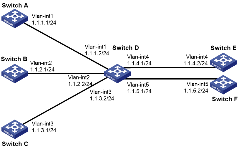
Example: Configuring packet type-based global PBR
Network configuration
As shown in Figure 5, Switch E and Switch F do not have a route to reach each other.
Configure global PBR on Switch D to forward TCP packets to the next hop 1.1.4.2 (Switch E).
Procedure
1. Assign IP addresses to the interfaces, as shown in Figure 5. (Details not shown.)
2. Configure unicast routing protocol settings to make sure Switch A, B and C can communicate with Switch E and Switch F, respectively. (Details not shown.)
3. Configure Switch D:
# Configure ACL 3101 to match TCP packets sourced from networks 1.1.1.0/24, 1.1.2.0/24, and 1.1.3.0/24.
<SwitchD> system-view
[SwitchD] acl advanced 3101
[SwitchD-acl-ipv4-adv-3101] rule permit tcp source 1.1.1.0 0.0.0.0.255
[SwitchD-acl-ipv4-adv-3101] rule permit tcp source 1.1.2.0 0.0.0.0.255
[SwitchD-acl-ipv4-adv-3101] rule permit tcp source 1.1.3.0 0.0.0.0.255
[SwitchD-acl-ipv4-adv-3101] quit
# Configure node 5 in PBR policy aaa to forward TCP packets that match ACL 3101 to next hop 1.1.4.2.
[SwitchD] policy-based-route aaa permit node 5
[SwitchD-pbr-aaa-5] if-match acl 3101
[SwitchD-pbr-aaa-5] apply next-hop 1.1.4.2
[SwitchD-pbr-aaa-5] quit
# Specify PBR policy aaa as the global PBR policy.
[SwitchD] ip global policy-based-route aaa
Verifying the configuration
1. Perform telnet operations to verify that global PBR on Switch D operates as configured to forward the matching TCP packets to the next hop 1.1.4.2 (Switch E), as follows:
# Verify that you can telnet to Switch E from Switch A, Switch B, and Switch C successfully. (Details not shown.)
# Verify that you cannot telnet to Switch F from Switch A, Switch B, or Switch C. (Details not shown.)
2. Verify that Switch D forwards packets other than TCP packets as long as a route is available. For example, verify that you can ping Switch F from Switch A, Switch B, and Switch C. (Details not shown.)
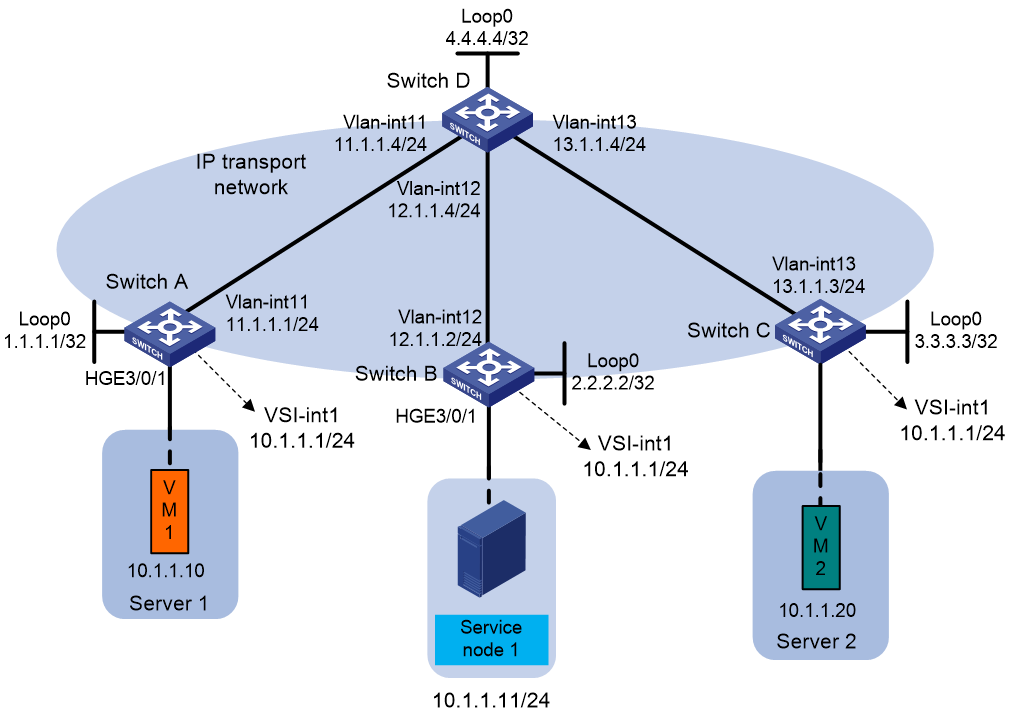
Example: Configuring EVPN-based service chain PBR
Network configuration
As shown in Figure 6, Switch A, Switch B, and Switch C are distributed EVPN gateway devices. Switch D acts as a route reflector to reflect BGP routes for the other switches.
Configure PBR to direct packets sent by Server 1 to Service node 1. After being processed, the packets are forwarded to Server 2.
Procedure
1. Configure IP addresses and subnet masks for interfaces, as shown in Figure 6. (Details not shown.)
2. Configure Switch A:
# Enable L2VPN.
<SwitchA> system-view
[SwitchA] l2vpn enable
# Disable remote-MAC address learning and remote ARP learning.
[SwitchA] vxlan tunnel mac-learning disable
[SwitchA] vxlan tunnel arp-learning disable
# Create an EVPN instance in VSI instance view, and configure the system to automatically generate an RT and RD.
[SwitchA] vsi vpna
[SwitchA-vsi-vpna] evpn encapsulation vxlan
[SwitchA-vsi-vpna-evpn-vxlan] route-distinguisher auto
[SwitchA-vsi-vpna-evpn-vxlan] vpn-target auto
[SwitchA-vsi-vpna-evpn-vxlan] quit
# Create VXLAN 10.
[SwitchA-vsi-vpna] vxlan 10
[SwitchA-vsi-vpna-vxlan-10] quit
[SwitchA-vsi-vpna] quit
# Configure BGP to advertise EVPN routes.
[SwitchA] bgp 200
[SwitchA-bgp-default] peer 4.4.4.4 as-number 200
[SwitchA-bgp-default] peer 4.4.4.4 connect-interface loopback 0
[SwitchA-bgp-default] address-family l2vpn evpn
[SwitchA-bgp-default-evpn] peer 4.4.4.4 enable
[SwitchA-bgp-default-evpn] quit
[SwitchA-bgp-default] quit
# Create VPN instance vpna.
[SwitchA] ip vpn-instance vpna
[SwitchA-vpn-instance-vpna] route-distinguisher 1:1
[SwitchA-vpn-instance-vpna] address-family ipv4
[SwitchA-vpn-ipv4-vpna] vpn-target 2:2
[SwitchA-vpn-ipv4-vpna] quit
[SwitchA-vpn-instance-vpna] address-family evpn
[SwitchA-vpn-evpn-vpna] vpn-target 1:1
[SwitchA-vpn-evpn-vpna] quit
[SwitchA-vpn-instance-vpna] quit
# Configure VSI-interface 1.
[SwitchA] interface vsi-interface 1
[SwitchA-Vsi-interface1] ip binding vpn-instance vpna
[SwitchA-Vsi-interface1] ip address 10.1.1.1 255.255.255.0
[SwitchA-Vsi-interface1] mac-address 0001-0001-0001
[SwitchA-Vsi-interface1] local-proxy-arp enable
[SwitchA-Vsi-interface1] distributed-gateway local
[SwitchA-Vsi-interface1] quit
# Configure VSI-interface 3, associate the interface with VPN instance vpna, and set the L3 VXLAN ID to 1000.
[SwitchA] interface vsi-interface 3
[SwitchA-Vsi-interface3] ip binding vpn-instance vpna
[SwitchA-Vsi-interface3] l3-vni 1000
[SwitchA-Vsi-interface3] quit
# Associate VSI instance vpna with VSI-interface 1.
[SwitchA] vsi vpna
[SwitchA-vsi-vpna] gateway vsi-interface 1
[SwitchA-vsi-vpna] quit
# Configure VLAN-interface 11.
[SwitchA] interface vlan-interface 11
[SwitchA-Vlan-interface11] ip address 11.1.1.1 255.255.255.0
[SwitchA-Vlan-interface11] ospf 1 area 0.0.0.0
[SwitchA-Vlan-interface11] quit
# Associate Ethernet service instance 1000 with VSI instance vpna.
[SwitchA] interface hundredgige 3/0/1
[SwitchA-HundredGigE3/0/1] port link-mode bridge
[SwitchA-HundredGigE3/0/1] service-instance 1000
[SwitchA-HundredGigE3/0/1-srv1000] encapsulation s-vid 2
[SwitchA-HundredGigE3/0/1-srv1000] xconnect vsi vpna
# Create ACL 3000 to permit packets with source IP address 10.1.1.10 and destination IP address 10.1.1.20.
<SwitchA> system-view
[SwitchA] acl advanced 3000
[SwitchA-acl-ipv4-adv-3000] rule 0 permit ip source 10.1.1.10 0 destination 10.1.1.20
# Create node 0 that uses ACL 3000 to filter packets. Apply next hop 10.1.1.11 and service chain path ID 1 to packets with source IP address 10.1.1.10 and destination IP address 10.1.1.20.
[SwitchA] policy-based-route aa permit node 0
[SwitchA-pbr-aa-0] if-match acl 3000
[SwitchA-pbr-aa-0] apply service-chain path-id 1
[SwitchA-pbr-aa-0] apply next-hop vpn-instance vpna 10.1.1.11
# Apply policy aa to VSI-interface 1.
[SwitchA] interface vsi-interface 1
[SwitchA-Vsi-interface1] ip policy-based-route aa
[SwitchA-Vsi-interface1] quit
3. Configure Switch B:
# Enable L2VPN.
<SwitchB> system-view
[SwitchB] l2vpn enable
# Disable remote-MAC address learning and remote ARP learning.
[SwitchB] vxlan tunnel mac-learning disable
[SwitchB] vxlan tunnel arp-learning disable
# Create an EVPN instance in VSI instance view, and configure the system to automatically generate an RT and RD.
[SwitchB] vsi vpna
[SwitchB-vsi-vpna] evpn encapsulation vxlan
[SwitchB-vsi-vpna-evpn-vxlan] route-distinguisher auto
[SwitchB-vsi-vpna-evpn-vxlan] vpn-target auto
[SwitchB-vsi-vpna-evpn-vxlan] quit
# Configure VXLAN 10.
[SwitchB-vsi-vpna] vxlan 10
[SwitchB-vsi-vpna-vxlan-10] quit
[SwitchB-vsi-vpna] quit
# Configure BGP to advertise EVPN routes.
[SwitchB] bgp 200
[SwitchB-bgp-default] peer 4.4.4.4 as-number 200
[SwitchB-bgp-default] peer 4.4.4.4 connect-interface loopback0
[SwitchB-bgp-default] address-family l2vpn evpn
[SwitchB-bgp-default-evpn] peer 4.4.4.4 enable
# Create VPN instance vpna.
[SwitchB] ip vpn-instance vpna
[SwitchB-vpn-instance-vpna] route-distinguisher 1:1
[SwitchB-vpn-instance-vpna] address-family ipv4
[SwitchB-vpn-ipv4-vpna] vpn-target 2:2
[SwitchB-vpn-ipv4-vpna] quit
[SwitchB-vpn-instance-vpna] address-family evpn
[SwitchB-vpn-evpn-vpna] vpn-target 1:1
[SwitchB-vpn-evpn-vpna] quit
[SwitchB-vpn-instance-vpna] quit
# Configure VSI-interface 1.
[SwitchB] interface vsi-interface 1
[SwitchB-Vsi-interface1] ip binding vpn-instance vpna
[SwitchB-Vsi-interface1] ip address 10.1.1.1 255.255.255.0
[SwitchB-Vsi-interface1] mac-address 0001-0001-0001
[SwitchB-Vsi-interface1] local-proxy-arp enable
[SwitchB-Vsi-interface1] distributed-gateway local
[SwitchB-Vsi-interface1] quit
# Associate VSI instance vpna with VSI-interface 1.
[SwitchB] vsi vpna
[SwitchB-vsi-vpna] gateway vsi-interface 1
[SwitchB-vsi-vpna] quit
# Configure VSI-interface 3.
[SwitchB] interface vsi-interface 3
[SwitchB-Vsi-interface3] ip binding vpn-instance vpna
[SwitchB-Vsi-interface3] l3-vni 1000
[SwitchB-Vsi-interface3] quit
# Configure HundredGigE 3/0/1 as an AC interface.
[SwitchB] interface hundredgige 3/0/1
[SwitchB-HundredGigE3/0/1] port link-mode bridge
[SwitchB-HundredGigE3/0/1] service-instance 1000
[SwitchB-HundredGigE3/0/1-srv1000] encapsulation s-vid 2
[SwitchB-HundredGigE3/0/1-srv1000] xconnect vsi vpna
[SwitchB-HundredGigE3/0/1-srv1000] quit
[SwitchB-HundredGigE3/0/1] quit
# Create node 0 and apply next hop 10.1.1.11 to packets with service chain path ID 1.
[SwitchB] policy-based-route aa permit node 0
[SwitchB-pbr-aa-0] if-match service-chain path-id 1
[SwitchB-pbr-aa-0] apply next-hop vpn-instance vpna 10.1.1.11
[SwitchB-pbr-aa-0] quit
# Apply policy aa to VSI-interface 3.
[SwitchB] interface vsi-interface 3
[SwitchB-Vsi-interface3] ip policy-based-route aa
[SwitchB-Vsi-interface3] quit
4. Configure Switch C:
# Enable L2VPN.
<SwitchC> system-view
[SwitchC] l2vpn enable
# Disable remote-MAC address learning and remote ARP learning.
[SwitchC] vxlan tunnel mac-learning disable
[SwitchC] vxlan tunnel arp-learning disable
# Create an EVPN instance in VSI instance view, and configure the system to automatically generate an RT and RD.
[SwitchC] vsi vpna
[SwitchC-vsi-vpna] evpn encapsulation vxlan
[SwitchC-vsi-vpna-evpn-vxlan] route-distinguisher auto
[SwitchC-vsi-vpna-evpn-vxlan] vpn-target auto
[SwitchC-vsi-vpna-evpn-vxlan] quit
# Configure VXLAN 10.
[SwitchC-vsi-vpna] vxlan 10
[SwitchC-vsi-vpna-vxlan-10] quit
[SwitchC-vsi-vpna] quit
# Configure BGP to advertise EVPN routes.
[SwitchC] bgp 200
[SwitchC-bgp-default] peer 4.4.4.4 as-number 200
[SwitchC-bgp-default] peer 4.4.4.4 connect-interface loopback 0
[SwitchC-bgp-default] address-family l2vpn evpn
[SwitchC-bgp-default-evpn] peer 4.4.4.4 enable
[SwitchC-bgp-default-evpn] quit
[SwitchC-bgp-default] quit
# Create VPN instance vpna.
[SwitchC] ip vpn-instance vpna
[SwitchC-vpn-instance-vpna] route-distinguisher 1:1
[SwitchC-vpn-instance-vpna] address-family ipv4
[SwitchC-vpn-ipv4-vpna] vpn-target 2:2
[SwitchC-vpn-ipv4-vpna] quit
[SwitchC-vpn-instance-vpna] address-family evpn
[SwitchC-vpn-evpn-vpna] vpn-target 1:1
[SwitchC-vpn-evpn-vpna] quit
[SwitchC-vpn-instance-vpna] quit
# Create VSI-interface 1, assign an IP address to it, and specify the interface as a distributed gateway in VXLAN 10.
[SwitchC] interface vsi-interface 1
[SwitchC-Vsi-interface1] ip binding vpn-instance vpna
[SwitchC-Vsi-interface1] ip address 10.1.1.1 255.255.255.0
[SwitchC-Vsi-interface1] mac-address 0001-0001-0001
[SwitchC-Vsi-interface1] local-proxy-arp enable
[SwitchC-Vsi-interface1] distributed-gateway local
[SwitchC-Vsi-interface1] quit
# Configure VSI-interface 3, associate the interface with VPN instance vpna, and set the L3 VXLAN ID to 1000.
[SwitchC] interface vsi-interface 3
[SwitchC-Vsi-interface3] ip binding vpn-instance vpna
[SwitchC-Vsi-interface3] l3-vni 1000
[SwitchC-Vsi-interface3] quit
# Associate VSI instance vpna with VSI-interface 1.
[SwitchC] vsi vpna
[SwitchC-vsi-vpna] gateway vsi-interface 1
[SwitchC-vsi-vpna] quit
# Bind VSI instance vpna to HundredGigE 3/0/1.
[SwitchC] interface hundredgige 3/0/1
[SwitchC-HundredGigE3/0/1] port link-mode bridge
[SwitchC-HundredGigE3/0/1] service-instance 2000
[SwitchC-HundredGigE3/0/1-srv2000] encapsulation s-vid 2
[SwitchC-HundredGigE3/0/1] xconnect vsi vpna
[SwitchC-HundredGigE3/0/1] quit
5. Configure Switch D:
# Configure Switch D to establish BGP connections with the other switches.
<SwitchD> system-view
[SwitchD] bgp 200
[SwitchD-bgp-default] group evpn
[SwitchD-bgp-default] peer 1.1.1.1 group evpn
[SwitchD-bgp-default] peer 2.2.2.2 group evpn
[SwitchD-bgp-default] peer 3.3.3.3 group evpn
[SwitchD-bgp-default] peer evpn as-number 200
[SwitchD-bgp-default] peer evpn connect-interface loopback 0
# Configure BGP to advertise EVPN routes, and disable route target filtering for BGP EVPN routes.
[SwitchD-bgp-default] address-family l2vpn evpn
[SwitchD-bgp-default-evpn] peer evpn enable
[SwitchD-bgp-default-evpn] undo policy vpn-target
# Configure Switch D as a route reflector.
[SwitchD-bgp-default-evpn] peer evpn reflect-client
[SwitchD-bgp-default-evpn] quit
[SwitchD-bgp-default] quit
# Configure VLAN-interface 11.
[SwitchD] interface vlan-interface 11
[SwitchD-Vlan-interface11] ip address 11.1.1.4 255.255.255.0
[SwitchD-Vlan-interface11] ospf 1 area 0.0.0.0
[SwitchD-Vlan-interface11] quit
# Configure VLAN-interface 12.
[SwitchD] interface vlan-interface 12
[SwitchD-Vlan-interface12] ip address 12.1.1.4 255.255.255.0
[SwitchD-Vlan-interface12] ospf 1 area 0.0.0.0
[SwitchD-Vlan-interface12] quit
# Configure VLAN-interface 13.
[SwitchD] interface Vlan-interface 13
[SwitchD-Vlan-interface13] ip address 13.1.1.4 255.255.255.0
[SwitchD-Vlan-interface13] ospf 1 area 0.0.0.0
[SwitchD-Vlan-interface13] quit
Verifying the configuration
# Capture packets sent from Server 1 to Server 2 in Ethernet service instance 1000. (Details not shown.)
The packets are processed by Service node 1 before they are delivered to Server 2.
