- Table of Contents
-
- 11-Network Management and Monitoring Configuration Examples
- 01-EAA Configuration Examples
- 02-Mirroring Configuration Examples
- 03-NQA Configuration Examples
- 04-NTP Configuration Examples
- 05-PTP Configuration Examples
- 06-sFlow Configuration Examples
- 07-SNMP Configuration Examples
- 08-VCF Fabric Configuration Examples
- Related Documents
-
| Title | Size | Download |
|---|---|---|
| 05-PTP Configuration Examples | 231.83 KB |
Example: Configuring Layer 2 IEEE 1588v2 PTP
Applicable hardware and software versions
Example: Configuring Layer 3 IEEE 1588v2 PTP in multicast mode
Applicable hardware and software versions
Example: Configuring Layer 3 IEEE 1588v2 PTP in unicast mode
Applicable hardware and software versions
Example: Configuring IEEE 802.1AS PTP
Applicable hardware and software versions
Example: Configuring SMPTE ST 2059-2 PTP in multicast mode
Applicable hardware and software versions
Example: Configuring SMPTE ST 2059-2 PTP in unicast mode
Applicable hardware and software versions
Introduction
This document provides PTP configuration examples.
Prerequisites
This document is not restricted to specific software or hardware versions.
The configuration examples in this document were created and verified in a lab environment, and all the devices were started with the factory default configuration. When you are working on a live network, make sure you understand the potential impact of every command on your network.
This document assumes that you have basic knowledge of PTP.
Example: Configuring Layer 2 IEEE 1588v2 PTP
Network configuration
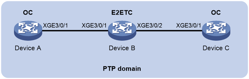
As shown in Figure 1, a PTP domain contains Device A, Device B, and Device C. Configure Layer 2 IEEE 1588v2 PTP as follows for time synchronization:
· Specify the IEEE 1588v2 PTP profile for the devices.
· Specify the OC clock node type for Device A and Device C, and E2ETC clock node type for Device B. These clock nodes elect a GM through BMC based on their respective default GM attributes.
Applicable hardware and software versions
The following matrix shows the hardware and software versions to which this configuration example is applicable:
|
Hardware |
Software version |
|
S12500G-AF |
Release 8053P05 and later |
|
S12500CR |
Release 8053P05 and later |
|
S10500X-G |
Release 7753P05 and later |
|
S7500X-G |
Not supported |
Procedures
Configuring Device A
# Specify the IEEE 1588v2 PTP profile.
<DeviceA> system-view
[DeviceA] ptp profile 1588v2
# Specify the OC clock node type.
[DeviceA] ptp mode oc
# Specify a PTP domain.
[DeviceA] ptp domain 0
# Enable PTP globally.
[DeviceA] ptp global enable
# Specify PTP for obtaining the time on the default MDC.
[DeviceA] clock protocol ptp mdc 1
# Enable PTP on Ten-GigabitEthernet 3/0/1.
[DeviceA] interface ten-gigabitEthernet3/0/1
[DeviceA-Ten-GigabitEthernet3/0/1] ptp enable
[DeviceA-Ten-GigabitEthernet3/0/1] quit
Configuring Device B
# Specify the IEEE 1588v2 PTP profile.
<DeviceB> system-view
[DeviceB] ptp profile 1588v2
# Specify the E2ETC clock node type.
[DeviceB] ptp mode e2etc
# Specify a PTP domain.
[DeviceB] ptp domain 0
# Enable PTP globally.
[DeviceB] ptp global enable
# Specify PTP for obtaining the time on the default MDC.
[DeviceB] clock protocol ptp mdc 1
# Enable PTP on Ten-GigabitEthernet 3/0/1.
[DeviceB] interface ten-gigabitEthernet3/0/1
[DeviceB-Ten-GigabitEthernet3/0/1] ptp enable
[DeviceB-Ten-GigabitEthernet3/0/1] quit
# Enable PTP on Ten-GigabitEthernet 3/0/2.
[DeviceB] interface ten-gigabitEthernet3/0/2
[DeviceB-Ten-GigabitEthernet3/0/2] ptp enable
[DeviceB-Ten-GigabitEthernet3/0/2] quit
Configuring Device C
# Specify the IEEE 1588v2 PTP profile.
<DeviceC> system-view
[DeviceC] ptp profile 1588v2
# Specify the OC clock node type.
[DeviceC] ptp mode oc
# Specify a PTP domain.
[DeviceC] ptp domain 0
# Enable PTP globally.
[DeviceC] ptp global enable
# Specify PTP for obtaining the time on the default MDC.
[DeviceC] clock protocol ptp mdc 1
# Enable PTP on Ten-GigabitEthernet 3/0/1.
[DeviceC] interface ten-gigabitEthernet3/0/1
[DeviceC-Ten-GigabitEthernet3/0/1] ptp enable
[DeviceC-Ten-GigabitEthernet3/0/1] quit
Verifying the configuration
When the network topology is stable, perform the following tasks to verify the PTP configuration:
· Use the display ptp clock command to display PTP clock information.
· Use the display ptp interface brief command to display brief information about PTP interfaces.
# Display PTP clock information on Device A.
[DeviceA] display ptp clock
PTP global state : Enabled
PTP profile : IEEE 1588 Version 2
PTP mode : OC
Slave only : No
Lock status : Locked
Clock ID : 000FE2-FFFE-FF0000
Clock type : Local
Clock domain : 0
Number of PTP ports : 1
Priority1 : 128
Priority2 : 128
Clock quality :
Class : 248
Accuracy : 254
Offset (log variance) : 65535
Offset from master : 0 (ns)
Mean path delay : 0 (ns)
Steps removed : 0
Local clock time : Sun Jan 15 20:57:29 2011
# Display brief information about PTP interfaces on Device A.
[DeviceA] display ptp interface brief
Name State Delay mechanism Clock step Asymmetry correction
XGE3/0/1 Master E2E Two 0
# Display PTP clock information on Device B.
[DeviceB] display ptp clock
PTP global state : Enabled
PTP profile : IEEE 1588 Version 2
PTP mode : E2ETC
Slave only : No
Lock status : Locked
Clock ID : 000FE2-FFFE-FF0001
Clock type : Local
Clock domain : 0
Number of PTP ports : 2
Priority1 : 128
Priority2 : 128
Clock quality :
Class : 248
Accuracy : 254
Offset (log variance) : 65535
Offset from master : N/A
Mean path delay : N/A
Steps removed : N/A
Local clock time : Sun Jan 15 20:57:29 2011
# Display brief information about PTP interfaces on Device B.
[DeviceB] display ptp interface brief
Name State Delay mechanism Clock step Asymmetry correction
XGE3/0/1 N/A E2E Two 0
XGE3/0/2 N/A E2E Two 0
# Display PTP clock information on Device C.
[DeviceC] display ptp clock
PTP global state : Enabled
PTP profile : IEEE 1588 Version 2
PTP mode : OC
Slave only : No
Lock status : Locked
Clock ID : 000FE2-FFFE-FF0002
Clock type : Local
Clock domain : 0
Number of PTP ports : 1
Priority1 : 128
Priority2 : 128
Clock quality :
Class : 248
Accuracy : 254
Offset (log variance) : 65535
Offset from master : 0 (ns)
Mean path delay : 0 (ns)
Steps removed : 0
Local clock time : Sun Jan 15 20:57:29 2019
# Display brief information about PTP interfaces on Device C.
[DeviceC] display ptp interface brief
Name State Delay mechanism Clock step Asymmetry correction
XGE3/0/1 Slave E2E Two 0
The command outputs show that Device A is elected as the GM and Ten-GigabitEthernet 3/0/1 on Device A is the master port.
Configuration files
· Device A and Device C:
#
clock protocol ptp mdc 1
#
ptp profile 1588v2
ptp mode oc
ptp domain 0
ptp global enable
#
interface Ten-gigabitEthernet3/0/1
ptp enable
#
· Device B:
#
clock protocol ptp mdc 1
#
ptp profile 1588v2
ptp mode e2etc
ptp domain 0
ptp global enable
#
interface Ten-gigabitEthernet3/0/1
ptp enable
#
interface Ten-gigabitEthernet3/0/2
ptp enable
#
Example: Configuring Layer 3 IEEE 1588v2 PTP in multicast mode
Network configuration
As shown in Figure 2, a PTP domain contains Device A, Device B, and Device C. Configure Layer 3 IEEE 1588v2 PTP in multicast mode as follows for time synchronization:
· Specify the IEEE 1588v2 PTP profile for the devices.
· Specify the OC clock node type for Device A and Device C, and the P2PTC clock node type for Device B. These clock nodes elect a GM through BMC based on their respective default GM attributes.
· Configure the multicast PTP transport mode and UDP (IPv4) transport protocol for the devices.
· Configure the peer delay measurement mechanism (p2p) for Device A and Device C.

Applicable hardware and software versions
The following matrix shows the hardware and software versions to which this configuration example is applicable:
|
Hardware |
Software version |
|
S12500G-AF |
Release 8053P05 and later |
|
S12500CR |
Release 8053P05 and later |
|
S10500X-G |
Release 7753P05 and later |
|
S7500X-G |
Not supported |
Procedures
Configuring Device A
# Specify the IEEE 1588v2 PTP profile.
<DeviceA> system-view
[DeviceA] ptp profile 1588v2
# Specify the OC clock node type.
[DeviceA] ptp mode oc
# Specify a PTP domain.
[DeviceA] ptp domain 0
# Enable PTP globally.
[DeviceA] ptp global enable
# Configure the source IP address for multicast PTP transport.
[DeviceA] ptp source 10.10.10.1
# Specify PTP for obtaining the time on the default MDC.
[DeviceA] clock protocol ptp mdc 1
# On Ten-GigabitEthernet 3/0/1, specify the UDP (IPv4) transport protocol and the peer delay measurement mechanism (p2p) and enable PTP.
[DeviceA] interface ten-gigabitEthernet3/0/1
[DeviceA-Ten-GigabitEthernet3/0/1] ptp transport-protocol udp
[DeviceA-Ten-GigabitEthernet3/0/1] ptp delay-mechanism p2p
[DeviceA-Ten-GigabitEthernet3/0/1] ptp enable
[DeviceA-Ten-GigabitEthernet3/0/1] quit
Configuring Device B
# Specify the IEEE 1588v2 PTP profile.
<DeviceB> system-view
[DeviceB] ptp profile 1588v2
# Specify the P2PTC clock node type.
[DeviceB] ptp mode p2ptc
# Specify a PTP domain.
[DeviceB] ptp domain 0
# Enable PTP globally.
[DeviceB] ptp global enable
# Configure the source IP address for multicast PTP transport.
[DeviceB] ptp source 10.10.10.2
# Specify PTP for obtaining the time on the default MDC.
[DeviceB] clock protocol ptp mdc 1
# On Ten-GigabitEthernet 3/0/1, specify the UDP (IPv4) transport protocol and enable PTP.
[DeviceB] interface ten-gigabitEthernet3/0/1
[DeviceB-Ten-GigabitEthernet3/0/1] ptp transport-protocol udp
[DeviceB-Ten-GigabitEthernet3/0/1] ptp enable
[DeviceB-Ten-GigabitEthernet3/0/1] quit
# On Ten-GigabitEthernet 3/0/2, specify the UDP transport protocol and enable PTP.
[DeviceB] interface ten-gigabitEthernet3/0/2
[DeviceB-Ten-GigabitEthernet3/0/2] ptp transport-protocol udp
[DeviceB-Ten-GigabitEthernet3/0/2] ptp enable
[DeviceB-Ten-GigabitEthernet3/0/2] quit
Configuring Device C
# Specify the IEEE 1588v2 PTP profile.
<DeviceC> system-view
[DeviceC] ptp profile 1588v2
# Specify the OC clock node type.
[DeviceC] ptp mode oc
# Specify a PTP domain.
[DeviceC] ptp domain 0
# Enable PTP globally.
[DeviceC] ptp global enable
# Configure the source IP address for multicast PTP transport.
[DeviceC] ptp source 11.10.10.1
# Specify PTP for obtaining the time on the default MDC.
[DeviceC] clock protocol ptp mdc 1
# On Ten-GigabitEthernet 3/0/1, specify the UDP (IPv4) transport protocol and the peer delay measurement mechanism (p2p) and enable PTP.
[DeviceC] interface ten-gigabitEthernet3/0/1
[DeviceC-Ten-GigabitEthernet3/0/1] ptp transport-protocol udp
[DeviceC-Ten-GigabitEthernet3/0/1] ptp delay-mechanism p2p
[DeviceC-Ten-GigabitEthernet3/0/1] ptp enable
[DeviceC-Ten-GigabitEthernet3/0/1] quit
Verifying the configuration
When the network topology is stable, perform the following tasks to verify the PTP configuration:
· Use the display ptp clock command to display PTP clock information.
· Use the display ptp interface brief command to display brief information about PTP interfaces.
# Display PTP clock information on Device A.
[DeviceA] display ptp clock
PTP global state : Enabled
PTP profile : IEEE 1588 Version 2
PTP mode : OC
Slave only : No
Lock status : Locked
Clock ID : 000FE2-FFFE-FF0000
Clock type : Local
Clock domain : 0
Number of PTP ports : 1
Priority1 : 128
Priority2 : 128
Clock quality :
Class : 248
Accuracy : 254
Offset (log variance) : 65535
Offset from master : 0 (ns)
Mean path delay : 0 (ns)
Steps removed : 0
Local clock time : Sun Jan 15 20:57:29 2011
# Display brief information about PTP interfaces on Device A.
[DeviceA] display ptp interface brief
Name State Delay mechanism Clock step Asymmetry correction
XGE3/0/1 Master P2P Two 0
# Display PTP clock information on Device B.
[DeviceB] display ptp clock
PTP global state : Enabled
PTP profile : IEEE 1588 Version 2
PTP mode : P2PTC
Slave only : No
Lock status : Locked
Clock ID : 000FE2-FFFE-FF0001
Clock type : Local
Clock domain : 0
Number of PTP ports : 2
Priority1 : 128
Priority2 : 128
Clock quality :
Class : 248
Accuracy : 254
Offset (log variance) : 65535
Offset from master : N/A
Mean path delay : N/A
Steps removed : N/A
Local clock time : Sun Jan 15 20:57:29 2011
# Display brief information about PTP interfaces on Device B.
[DeviceB] display ptp interface brief
Name State Delay mechanism Clock step Asymmetry correction
XGE3/0/1 N/A P2P Two 0
XGE3/0/2 N/A P2P Two 0
# Display PTP clock information on Device C.
[DeviceC] display ptp clock
PTP global state : Enabled
PTP profile : IEEE 1588 Version 2
PTP mode : OC
Slave only : No
Lock status : Locked
Clock ID : 000FE2-FFFE-FF0002
Clock type : Local
Clock domain : 0
Number of PTP ports : 1
Priority1 : 128
Priority2 : 128
Clock quality :
Class : 248
Accuracy : 254
Offset (log variance) : 65535
Offset from master : 0 (ns)
Mean path delay : 0 (ns)
Steps removed : 0
Local clock time : Sun Jan 15 20:57:29 2019
# Display brief information about PTP interfaces on Device C.
[DeviceC] display ptp interface brief
Name State Delay mechanism Clock step Asymmetry correction
XGE3/0/1 Slave P2P Two 0
The command outputs show that Device A is elected as the GM and Ten-GigabitEthernet 3/0/1 on Device A is the master port.
Configuration files
· Device A:
#
clock protocol ptp mdc 1
#
ptp profile 1588v2
ptp mode oc
ptp domain 0
ptp global enable
ptp source 10.10.10.1
#
interface Ten-GigabitEthernet3/0/1
ptp delay-mechanism p2p
ptp transport-protocol udp
ptp enable
#
· Device B:
#
clock protocol ptp mdc 1
#
ptp profile 1588v2
ptp mode p2ptc
ptp domain 0
ptp global enable
ptp source 10.10.10.2
#
interface Ten-GigabitEthernet3/0/1
ptp transport-protocol udp
ptp enable
#
interface Ten-GigabitEthernet3/0/2
ptp transport-protocol udp
ptp enable
#
· Device C:
#
clock protocol ptp mdc 1
#
ptp profile 1588v2
ptp mode oc
ptp domain 0
ptp global enable
ptp source 11.10.10.1
#
interface Ten-GigabitEthernet3/0/1
ptp delay-mechanism p2p
ptp transport-protocol udp
ptp enable
#
Example: Configuring Layer 3 IEEE 1588v2 PTP in unicast mode
Network configuration
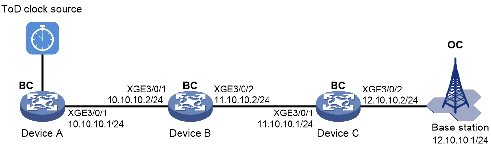
As shown in Figure 3, configure PTP (IEEE 1588 version 2, IPv4 UDP transport, and unicast transmission) to enable Device A, Device B, Device C, and the base station to synchronize the time with the ToD clock source.
· Specify the IEEE 1588 version 2 PTP profile and unicast IPv4 UDP transport of PTP messages for Device A, Device B, and Device C.
· Assign Device A, Device B, Device C, and the base station to PTP domain 0. Specify the BC clock node type for Device A, Device B, and Device C.
· Connect Device A to the ToD clock source and Device C to the base station.
· Use the default Request_Response delay measurement mechanism on all clock nodes in the PTP domain.
Applicable hardware and software versions
The following matrix shows the hardware and software versions to which this configuration example is applicable:
|
Hardware |
Software version |
|
S12500G-AF |
Release 8053P05 and later |
|
S12500CR |
Release 8053P05 and later |
|
S10500X-G |
Release 7753P05 and later |
|
S7500X-G |
Not supported |
Prerequisites
As shown in Figure 3, assign IP addresses to the interfaces and make sure the devices can reach each other. (Details not shown.)
Procedures
Configuring Device A
# Specify the IEEE 1588v2 PTP profile.
<DeviceA> system-view
[DeviceA] ptp profile 1588v2
# Specify the BC clock node type.
[DeviceA] ptp mode bc
# Specify a PTP domain.
[DeviceA] ptp domain 0
# Enable PTP globally.
[DeviceA] ptp global enable
# Configure the device to receive ToD clock signals and set the delay time correction to 1000 nanoseconds.
[DeviceA] ptp tod0 input delay 1000
# Set priority 1 to 0 for the ToD clock.
[DeviceA] ptp priority clock-source tod0 priority1 0
# On Ten-GigabitEthernet 3/0/1, specify the UDP (IPv4) transport protocol and a unicast destination IP address for PTP messages and enable PTP.
[DeviceA] interface ten-gigabitEthernet3/0/1
[DeviceA-Ten-GigabitEthernet3/0/1] ptp transport-protocol udp
[DeviceA-Ten-GigabitEthernet3/0/1] ptp unicast-destination 10.10.10.2
[DeviceA-Ten-GigabitEthernet3/0/1] ptp enable
[DeviceA-Ten-GigabitEthernet3/0/1] quit
Configuring Device B
# Specify the IEEE 1588v2 PTP profile.
<DeviceB> system-view
[DeviceB] ptp profile 1588v2
# Specify the BC clock node type.
[DeviceB] ptp mode bc
# Specify a PTP domain.
[DeviceB] ptp domain 0
# Enable PTP globally.
[DeviceB] ptp global enable
# Specify PTP for obtaining the time on the default MDC.
[DeviceB] clock protocol ptp mdc 1
# On Ten-GigabitEthernet 3/0/1, specify the UDP (IPv4) transport protocol and a unicast destination IP address for PTP messages and enable PTP.
[DeviceB] interface ten-gigabitEthernet3/0/1
[DeviceB-Ten-GigabitEthernet3/0/1] ptp transport-protocol udp
[DeviceB-Ten-GigabitEthernet3/0/1] ptp unicast-destination 10.10.10.1
[DeviceB-Ten-GigabitEthernet3/0/1] ptp enable
[DeviceB-Ten-GigabitEthernet3/0/1] quit
# On Ten-GigabitEthernet 3/0/2, specify the UDP (IPv4) transport protocol and a unicast destination IP address for PTP messages and enable PTP.
[DeviceB] interface ten-gigabitEthernet3/0/2
[DeviceB-Ten-GigabitEthernet3/0/2] ptp transport-protocol udp
[DeviceB-Ten-GigabitEthernet3/0/2] ptp unicast-destination 11.10.10.1
[DeviceB-Ten-GigabitEthernet3/0/2] ptp enable
[DeviceB-Ten-GigabitEthernet3/0/2] quit
Configuring Device C
# Specify the IEEE 1588v2 PTP profile.
<DeviceC> system-view
[DeviceC] ptp profile 1588v2
# Specify the BC clock node type.
[DeviceC] ptp mode bc
# Specify a PTP domain.
[DeviceC] ptp domain 0
# Enable PTP globally.
[DeviceC] ptp global enable
# Specify PTP for obtaining the time on the default MDC.
[DeviceC] clock protocol ptp mdc 1
# On Ten-GigabitEthernet 3/0/1, specify the UDP (IPv4) transport protocol and a unicast destination IP address for PTP messages and enable PTP.
[DeviceC] interface ten-gigabitEthernet3/0/1
[DeviceC-Ten-GigabitEthernet3/0/1] ptp transport-protocol udp
[DeviceC-Ten-GigabitEthernet3/0/1] ptp unicast-destination 11.10.10.2
[DeviceC-Ten-GigabitEthernet3/0/1] ptp enable
[DeviceC-Ten-GigabitEthernet3/0/1] quit
# On GigabitEthernet 3/0/2, specify the UDP (IPv4) transport protocol and a unicast destination IP address for PTP messages and enable PTP.
[DeviceC] interface ten-gigabitEthernet3/0/2
[DeviceC-Ten-GigabitEthernet3/0/2] ptp transport-protocol udp
[DeviceC-Ten-GigabitEthernet3/0/2] ptp unicast-destination 12.10.10.1
[DeviceC-Ten-GigabitEthernet3/0/2] ptp enable
[DeviceC-Ten-GigabitEthernet3/0/2] quit
Configuring the base station
# Specify PTP domain 0.
# Specify IPv4 UDP transport of PTP messages.
# Set the destination IP address of unicast PTP messages to 12.10.10.2.
# Specify the Request_Response delay measurement mechanism.
For more information, see the configuration guide for the base station.
Verifying the configuration
When the network topology is stable, perform the following tasks to verify the PTP configuration:
· Use the display ptp clock command to display PTP clock information.
· Use the display ptp interface brief command to display brief information about PTP interfaces.
# Display PTP clock information on Device A.
[DeviceA] display ptp clock
PTP global state : Enabled
PTP profile : IEEE 1588 Version 2
PTP mode : BC
Slave only : No
Lock status : Locked
Clock ID : 000FE2-FFFE-FF0000
Clock type : ToD0
ToD direction : In
ToD delay time : 1000 (ns)
Clock domain : 0
Number of PTP ports : 1
Priority1 : 0
Priority2 : 128
Clock quality :
Class : 6
Accuracy : 32
Offset (log variance) : 65535
Offset from master : 0 (ns)
Mean path delay : 0 (ns)
Steps removed : 0
Local clock time : Sun Jan 15 20:57:29 2011
# Display brief information about PTP interfaces on Device A.
[DeviceA] display ptp interface brief
Name State Delay mechanism Clock step Asymmetry correction
XGE3/0/1 Master E2E Two 0
# Display PTP clock information on Device B.
[DeviceB] display ptp clock
PTP global state : Enabled
PTP profile : IEEE 1588 Version 2
PTP mode : BC
Slave only : No
Lock status : Locked
Clock ID : 000FE2-FFFE-FF0001
Clock type : Local
Clock domain : 0
Number of PTP ports : 2
Priority1 : 128
Priority2 : 128
Clock quality :
Class : 248
Accuracy : 254
Offset (log variance) : 65535
Offset from master : N/A
Mean path delay : N/A
Steps removed : N/A
Local clock time : Sun Jan 15 20:57:29 2011
# Display brief information about PTP interfaces on Device B.
[DeviceB] display ptp interface brief
Name State Delay mechanism Clock step Asymmetry correction
XGE3/0/1 N/A E2E Two 0
XGE3/0/2 N/A E2E Two 0
# Display PTP clock information on Device C.
[DeviceC] display ptp clock
PTP global state : Enabled
PTP profile : IEEE 1588 Version 2
PTP mode : BC
Slave only : No
Lock status : Locked
Clock ID : 000FE2-FFFE-FF0002
Clock type : Local
Clock domain : 0
Number of PTP ports : 1
Priority1 : 128
Priority2 : 128
Clock quality :
Class : 248
Accuracy : 254
Offset (log variance) : 65535
Offset from master : 0 (ns)
Mean path delay : 0 (ns)
Steps removed : 0
Local clock time : Sun Jan 15 20:57:29 2019
# Display brief information about PTP interfaces on Device C.
[DeviceC] display ptp interface brief
Name State Delay mechanism Clock step Asymmetry correction
XGE3/0/1 0 Slave E2E Two 0
XGE3/0/2 0 Master E2E Two 0
The command outputs show that Device A is elected as the GM and Ten-GigabitEthernet 3/0/1 on Device A is the master port.
Configuration files
· Device A:
#
ptp profile 1588v2
ptp mode bc
ptp domain 0
ptp global enable
ptp tod0 input delay 1000
ptp priority clock-source tod0 priority1 0
#
interface Ten-GigabitEthernet3/0/1
ptp transport-protocol udp
ptp unicast-destination 10.10.10.2
ptp enable
#
· Device B:
#
clock protocol ptp mdc 1
#
ptp profile 1588v2
ptp mode bc
ptp domain 0
ptp global enable
#
interface Ten-GigabitEthernet3/0/1
ptp transport-protocol udp
ptp unicast-destination 10.10.10.1
ptp enable
#
interface Ten-GigabitEthernet3/0/2
ptp transport-protocol udp
ptp unicast-destination 11.10.10.1
ptp enable
#
· Device C:
#
clock protocol ptp mdc 1
#
ptp profile 1588v2
ptp mode bc
ptp domain 0
ptp global enable
#
interface Ten-GigabitEthernet3/0/1
ptp transport-protocol udp
ptp unicast-destination 11.10.10.2
ptp enable
#
# interface Ten-GigabitEthernet3/0/1
ptp transport-protocol
ptp unicast-destination 12.10.10.1
ptp enable
#
Example: Configuring IEEE 802.1AS PTP
Network configuration
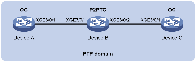
As shown in Figure 4, a PTP domain contains Device A, Device B, and Device C. Configure IEEE 802.1AS PTP as follows for time synchronization:
· Specify the IEEE 802.1AS PTP profile for the devices.
· Specify the OC clock node type for Device A and Device C, and the P2PTC clock node type for Device B. These clock nodes elect a GM through BMC based on their respective default GM attributes.
Applicable hardware and software versions
The following matrix shows the hardware and software versions to which this configuration example is applicable:
|
Hardware |
Software version |
|
S12500G-AF |
Release 8053P05 and later |
|
S12500CR |
Release 8053P05 and later |
|
S10500X-G |
Release 7753P05 and later |
|
S7500X-G |
Not supported |
Procedures
Configuring Device A
# Specify the IEEE 802.1AS PTP profile.
<DeviceA> system-view
[DeviceA] ptp profile 802.1AS
# Specify the OC clock node type.
[DeviceA] ptp mode oc
# Specify a PTP domain.
[DeviceA] ptp domain 0
# Enable PTP globally.
[DeviceA] ptp global enable
# Specify PTP for obtaining the time on the default MDC.
[DeviceA] clock protocol ptp mdc 1
# Enable PTP on Ten-GigabitEthernet 3/0/1.
[DeviceA] interface ten-gigabitEthernet 3/0/1
[DeviceA-Ten-GigabitEthernet3/0/1] ptp enable
[DeviceA-Ten-GigabitEthernet3/0/1] quit
Configuring Device B
# Specify the IEEE 802.1AS PTP profile.
<DeviceB> system-view
[DeviceB] ptp profile 802.1AS
# Specify the P2PTC clock node type.
[DeviceB] ptp mode p2ptc
# Specify a PTP domain.
[DeviceB] ptp domain 0
# Enable PTP globally.
[DeviceB] ptp global enable
# Specify PTP for obtaining the time on the default MDC.
[DeviceB] clock protocol ptp mdc 1
# Enable PTP on Ten-GigabitEthernet 3/0/1.
[DeviceB] interface ten-gigabitEthernet3/0/1
[DeviceB-Ten-GigabitEthernet3/0/1] ptp enable
[DeviceB-Ten-GigabitEthernet3/0/1] quit
# Enable PTP on Ten-GigabitEthernet 3/0/2.
[DeviceB] interface ten-gigabitEthernet3/0/2
[DeviceB-Ten-GigabitEthernet3/0/2] ptp enable
[DeviceB-Ten-GigabitEthernet3/0/2] quit
Configuring Device C
# Specify the IEEE 1588 802.1AS PTP profile.
<DeviceC> system-view
[DeviceC] ptp profile 802.1AS
# Specify the OC clock node type.
[DeviceC] ptp mode oc
# Specify a PTP domain.
[DeviceC] ptp domain 0
# Enable PTP globally.
[DeviceC] ptp global enable
# Specify PTP for obtaining the time on the default MDC.
[DeviceC] clock protocol ptp mdc 1
# Enable PTP on Ten-GigabitEthernet 3/0/1.
[DeviceC] interface ten-gigabitEthernet3/0/1
[DeviceC-Ten-GigabitEthernet3/0/1] ptp enable
[DeviceC-Ten-GigabitEthernet3/0/1] quit
Verifying the configuration
When the network topology is stable, perform the following tasks to verify the PTP configuration:
· Use the display ptp clock command to display PTP clock information.
· Use the display ptp interface brief command to display brief information about PTP interfaces.
# Display PTP clock information on Device A.
[DeviceA] display ptp clock
PTP global state : Enabled
PTP profile : IEEE 802.1AS
PTP mode : OC
Slave only : No
Lock status : Locked
Clock ID : 000FE2-FFFE-FF0000
Clock type : Local
Clock domain : 0
Number of PTP ports : 1
Priority1 : 246
Priority2 : 248
Clock quality :
Class : 248
Accuracy : 254
Offset (log variance) : 16640
Offset from master : 0 (ns)
Mean path delay : 0 (ns)
Steps removed : 0
Local clock time : Sun Jan 15 20:57:29 2011
# Display brief information about PTP interfaces on Device A.
[DeviceA] display ptp interface brief
Name State Delay mechanism Clock step Asymmetry correction
XGE3/0/1 Master P2P Two 0
# Display PTP clock information on Device B.
[DeviceB] display ptp clock
PTP global state : Enabled
PTP profile : IEEE 802.1AS
PTP mode : P2PTC
Slave only : No
Lock status : Locked
Clock ID : 000FE2-FFFE-FF0001
Clock type : Local
Clock domain : 0
Number of PTP ports : 2
Priority1 : 246
Priority2 : 248
Clock quality :
Class : 248
Accuracy : 254
Offset (log variance) : 16640
Offset from master : N/A
Mean path delay : N/A
Steps removed : N/A
Local clock time : Sun Jan 15 20:57:29 2011
# Display brief information about PTP interfaces on Device B.
[DeviceB] display ptp interface brief
Name State Delay mechanism Clock step Asymmetry correction
XGE3/0/1 N/A P2P Two 0
XGE3/0/2 N/A P2P Two 0
# Display PTP clock information on Device C.
[DeviceC] display ptp clock
PTP global state : Enabled
PTP profile : IEEE 802.1AS
PTP mode : OC
Slave only : No
Lock status : Locked
Clock ID : 000FE2-FFFE-FF0002
Clock type : Local
Clock domain : 0
Number of PTP ports : 1
Priority1 : 128
Priority2 : 128
Clock quality :
Class : 248
Accuracy : 254
Offset (log variance) : 65535
Offset from master : 0 (ns)
Mean path delay : 0 (ns)
Steps removed : 0
Local clock time : Sun Jan 15 20:57:29 2019
# Display brief information about PTP interfaces on Device C.
[DeviceC] display ptp interface brief
Name State Delay mechanism Clock step Asymmetry correction
XGE3/0/1 Slave P2P Two 0
The command outputs show that Device A is elected as the GM and Ten-GigabitEthernet 3/0/1 on Device A is the master port.
Configuration files
· Device A and Device C:
#
clock protocol ptp mdc 1
#
ptp profile 8021as
ptp mode oc
ptp domain 0
ptp global enable
#
interface Ten-GigabitEthernet3/0/1
ptp enable
#
· Device B:
#
clock protocol ptp mdc 1
#
ptp profile 8021as
ptp mode p2ptc
ptp domain 0
ptp global enable
#
interface Ten-GigabitEthernet3/0/1
ptp enable
#
interface Ten-GigabitEthernet3/0/2
ptp enable
#
Example: Configuring SMPTE ST 2059-2 PTP in multicast mode
Network configuration
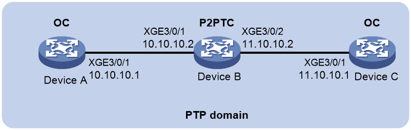
As shown in Figure 5, Device A, Device B, and Device C are in a PTP domain. Configure SMPTE ST 2059-2 PTP in multicast mode as follows for time synchronization:
· Specify the SMPTE ST 2059-2 PTP profile for the devices.
· Configure the multicast PTP transport mode for the devices.
· Specify the OC clock node type for Device A and Device C, and the P2PTC clock node type for Device B. All clock nodes elect a GM through BMC based on their respective default GM attributes.
· Configure the peer delay measurement mechanism (p2p) for Device A and Device C.
Applicable hardware and software versions
The following matrix shows the hardware and software versions to which this configuration example is applicable:
|
Hardware |
Software version |
|
S12500G-AF |
Release 8053P05 and later |
|
S12500CR |
Release 8053P05 and later |
|
S10500X-G |
Release 7753P05 and later |
|
S7500X-G |
Not supported |
Procedures
Configuring Device A
# Specify the SMPTE ST 2059-2 PTP profile.
<DeviceA> system-view
[DeviceA] ptp profile st2059-2
# Specify the OC clock node type.
[DeviceA] ptp mode oc
# Specify a PTP domain.
[DeviceA] ptp domain 0
# Enable PTP globally.
[DeviceA] ptp global enable
# Configure the source IP address for multicast PTP transport.
[DeviceA] ptp source 10.10.10.1
# Specify PTP for obtaining the time on the default MDC.
[DeviceA] clock protocol ptp mdc 1
# On Ten-GigabitEthernet 3/0/1, specify the peer delay measurement mechanism (p2p) and enable PTP.
[DeviceA] interface ten-gigabitEthernet3/0/1
[DeviceA-Ten-GigabitEthernet3/0/1] ptp delay-mechanism p2p
[DeviceA-Ten-GigabitEthernet3/0/1] ptp enable
[DeviceA-Ten-GigabitEthernet3/0/1] quit
Configuring Device B
# Specify the SMPTE ST 2059-2 PTP profile.
<DeviceB> system-view
[DeviceB] ptp profile st2059-2
# Specify the P2PTC clock node type.
[DeviceB] ptp mode p2ptc
# Specify a PTP domain.
[DeviceB] ptp domain 0
# Enable PTP globally.
[DeviceB] ptp global enable
# Configure the source IP address for multicast PTP transport.
[DeviceB] ptp source 10.10.10.2
# Specify PTP for obtaining the time on the default MDC.
[DeviceB] clock protocol ptp mdc 1
# Enable PTP on Ten-GigabitEthernet 3/0/1.
[DeviceB] interface ten-gigabitEthernet3/0/1
[DeviceB-Ten-GigabitEthernet3/0/1] ptp enable
[DeviceB-Ten-GigabitEthernet3/0/1] quit
# Enable PTP on Ten-GigabitEthernet 3/0/2.
[DeviceB] interface ten-gigabitEthernet3/0/2
[DeviceB-Ten-GigabitEthernet3/0/2] ptp enable
[DeviceB-Ten-GigabitEthernet3/0/2] quit
Configuring Device C
# Specify the SMPTE ST 2059-2 PTP profile.
<DeviceC> system-view
[DeviceC] ptp profile st2059-2
# Specify the OC clock node type.
[DeviceC] ptp mode oc
# Specify a PTP domain.
[DeviceC] ptp domain 0
# Enable PTP globally.
[DeviceC] ptp global enable
# Configure the source IP address for multicast PTP transport.
[DeviceC] ptp source 11.10.10.1
# Specify PTP for obtaining the time on the default MDC.
[DeviceC] clock protocol ptp mdc 1
# On Ten-GigabitEthernet 3/0/1, specify the peer delay measurement mechanism (p2p) and enable PTP.
[DeviceC] interface ten-gigabitEthernet 3/0/1
[DeviceC-Ten-GigabitEthernet3/0/1] ptp delay-mechanism p2p
[DeviceC-Ten-GigabitEthernet3/0/1] ptp enable
[DeviceC-Ten-GigabitEthernet3/0/1] quit
Verifying the configuration
When the network topology is stable, perform the following tasks to verify the PTP configuration:
· Use the display ptp clock command to display PTP clock information.
· Use the display ptp interface brief command to display brief information about PTP interfaces.
# Display PTP clock information on Device A.
[DeviceA] display ptp clock
PTP global state : Enabled
PTP profile : SMPTE ST 2059-2
PTP mode : OC
Slave only : No
Lock status : Locked
Clock ID : 000FE2-FFFE-FF0000
Clock type : Local
Clock domain : 0
Number of PTP ports : 1
Priority1 : 128
Priority2 : 128
Clock quality :
Class : 248
Accuracy : 254
Offset (log variance) : 65535
Offset from master : 0 (ns)
Mean path delay : 0 (ns)
Steps removed : 0
Local clock time : Sun Jan 15 20:57:29 2011
# Display brief information about PTP interfaces on Device A.
[DeviceA] display ptp interface brief
Name State Delay mechanism Clock step Asymmetry correction
XGE3/0/1 Master P2P Two 0
# Display PTP clock information on Device B.
[DeviceB] display ptp clock
PTP global state : Enabled
PTP profile : SMPTE ST 2059-2
PTP mode : P2PTC
Slave only : No
Lock status : Locked
Clock ID : 000FE2-FFFE-FF0001
Clock type : Local
Clock domain : 0
Number of PTP ports : 2
Priority1 : 128
Priority2 : 128
Clock quality :
Class : 248
Accuracy : 254
Offset (log variance) : 65535
Offset from master : N/A
Mean path delay : N/A
Steps removed : N/A
Local clock time : Sun Jan 15 20:57:29 2011
# Display brief information about PTP interfaces on Device B.
[DeviceB] display ptp interface brief
Name State Delay mechanism Clock step Asymmetry correction
XGE3/0/1 N/A P2P Two 0
XGE3/0/2 N/A P2P Two 0
# Display PTP clock information on Device C.
[DeviceC] display ptp clock
PTP global state : Enabled
PTP profile : SMPTE ST 2059-2
PTP mode : OC
Slave only : No
Lock status : Locked
Clock ID : 000FE2-FFFE-FF0002
Clock type : Local
Clock domain : 0
Number of PTP ports : 1
Priority1 : 128
Priority2 : 128
Clock quality :
Class : 248
Accuracy : 254
Offset (log variance) : 65535
Offset from master : 0 (ns)
Mean path delay : 0 (ns)
Steps removed : 0
Local clock time : Sun Jan 15 20:57:29 2019
# Display brief information about PTP interfaces on Device C.
[DeviceC] display ptp interface brief
Name State Delay mechanism Clock step Asymmetry correction
XGE3/0/1 Slave P2P Two 0
The output shows that Device A is elected as the GM and Ten-GigabitEthernet 3/0/1 on Device A is the master port.
Configuration files
· Device A:
#
clock protocol ptp mdc 1
#
ptp profile st2059-2
ptp mode oc
ptp domain 0
ptp global enable
ptp source 10.10.10.1
#
interface Ten-GigabitEthernet3/0/1
ptp delay-mechanism p2p
ptp enable
#
· Device B:
#
clock protocol ptp mdc 1
#
ptp profile st2059-2
ptp mode p2ptc
ptp domain 0
ptp global enable
ptp source 10.10.10.2
#
interface Ten-GigabitEthernet3/0/1
ptp enable
#
interface Ten-GigabitEthernet3/0/2
ptp enable
#
· Device C:
#
clock protocol ptp mdc 1
#
ptp profile st2059-2
ptp mode oc
ptp domain 0
ptp global enable
ptp source 11.10.10.1
#
interface Ten-GigabitEthernet3/0/1
ptp delay-mechanism p2p
ptp enable
#
Example: Configuring SMPTE ST 2059-2 PTP in unicast mode
Network configuration
As shown in Figure 6, configure PTP (SMPTE ST 2059-2, IPv4 UDP transport, unicast transmission) to enable Device A, Device B, Device C, and the base station to synchronize time with the ToD clock source .
· Specify the SMPTE ST 2059-2 PTP profile and unicast IPv4 UDP transport of PTP messages for Device A, Device B, and Device C.
· Assign Device A, Device B, Device C, and the base station to PTP domain 0. Specify the BC clock node type for Device A, Device B, and Device C.
· Connect Device A to the ToD clock source and Device C to the base station.
· Use the default Request_Response delay measurement mechanism on all clock nodes in the PTP domain.

Applicable hardware and software versions
The following matrix shows the hardware and software versions to which this configuration example is applicable:
|
Hardware |
Software version |
|
S12500G-AF |
Release 8053P05 and later |
|
S12500CR |
Release 8053P05 and later |
|
S10500X-G |
Release 7753P05 and later |
|
S7500X-G |
Not supported |
Prerequisites
As shown in Figure 6, assign IP addresses to the interfaces, and make sure the devices can reach each other. (Details not shown.)
Procedures
|
|
IMPORTANT: The SMPTE ST 2059-2 PTP profile supports IPv4 UDP transport rather than IEEE 802.3/Ethernet transport of PTP messages. It supports both multicast and unicast transmission of PTP messages. |
Configuring Device A
# Specify the SMPTE ST 2059-2 PTP profile.
<DeviceA> system-view
[DeviceA] ptp profile st2059-2
# Specify the OC clock node type.
[DeviceA] ptp mode oc
# Specify a PTP domain.
[DeviceA] ptp domain 0
# Enable PTP globally.
[DeviceA] ptp global enable
# Configure the device to receive ToD clock signals and set the delay correction value to 1000 nanoseconds.
[DeviceA] ptp tod0 input delay 1000
# Set priority 1 to 0 for the ToD clock.
[DeviceA] ptp priority clock-source tod0 priority1 0
# On Ten-GigabitEthernet 3/0/1, specify a unicast destination IP address for PTP messages and enable PTP.
[DeviceA] interface ten-gigabitEthernet 3/0/1
[DeviceA-Ten-GigabitEthernet3/0/1] ptp unicast-destination 10.10.10.2
[DeviceA-Ten-GigabitEthernet3/0/1] ptp enable
[DeviceA-Ten-GigabitEthernet3/0/1] quit
Configuring Device B
# Specify the SMPTE ST 2059-2 PTP profile.
<DeviceB> system-view
[DeviceB] ptp profile st2059-2
# Specify the BC clock node type.
[DeviceB] ptp mode bc
# Specify a PTP domain.
[DeviceB] ptp domain 0
# Enable PTP globally.
[DeviceB] ptp global enable
# Specify PTP for obtaining the time on the default MDC.
[DeviceB] clock protocol ptp mdc 1
# On Ten-GigabitEthernet 3/0/1, specify a unicast destination IP address for PTP messages and enable PTP.
[DeviceB] interface ten-gigabitEthernet3/0/1
[DeviceB-Ten-GigabitEthernet3/0/1] ptp unicast-destination 10.10.10.1
[DeviceB-Ten-GigabitEthernet3/0/1] ptp enable
[DeviceB-Ten-GigabitEthernet3/0/1] quit
# On Ten-GigabitEthernet 3/0/2, specify a unicast destination IP address for PTP messages and enable PTP.
[DeviceB] interface ten-gigabitEthernet3/0/2
[DeviceB-Ten-GigabitEthernet3/0/2] ptp unicast-destination 11.10.10.1
[DeviceB-Ten-GigabitEthernet3/0/2] ptp enable
[DeviceB-Ten-GigabitEthernet3/0/2] quit
Configuring Device C
# Specify the SMPTE ST 2059-2 PTP profile.
<DeviceC> system-view
[DeviceC] ptp profile st2059-2
# Specify the BC clock node type.
[DeviceC] ptp mode bc
# Specify a PTP domain.
[DeviceC] ptp domain 0
# Enable PTP globally.
[DeviceC] ptp global enable
# Specify PTP for obtaining the time on the default MDC.
[DeviceC] clock protocol ptp mdc 1
# On Ten-GigabitEthernet 3/0/1, specify a unicast destination IP address for PTP messages and enable PTP.
[DeviceC] interface ten-gigabitEthernet 3/0/1
[DeviceC-Ten-GigabitEthernet3/0/1] ptp unicast-destination 11.10.10.2
[DeviceC-Ten-GigabitEthernet3/0/1] ptp enable
[DeviceC-Ten-GigabitEthernet3/0/1] quit
# On Ten-GigabitEthernet 3/0/2, configure the destination IP address for unicast PTP messages and enable PTP. (The SMPTE ST 2059-2 PTP profile transports PTP messages over IPv4 UDP by default.)
[DeviceC] interface ten-gigabitEthernet 3/0/2
[DeviceC-Ten-GigabitEthernet3/0/2] ptp unicast-destination 12.10.10.1
[DeviceC-Ten-GigabitEthernet3/0/2] ptp enable
[DeviceC-Ten-GigabitEthernet3/0/2] quit
Configure the base station.
# Specify PTP domain 0.
# Specify IPv4 UDP transport of PTP messages.
# Set the destination IP address of unicast PTP messages to 12.10.10.2.
# Specify the Request_Response delay measurement mechanism.
For more information, see the configuration guide for the base station.
Verifying the configuration
When the network topology is stable, perform the following tasks to verify the PTP configuration:
· Use the display ptp clock command to display PTP clock information.
· Use the display ptp interface brief command to display brief information about PTP interfaces.
# Display PTP clock information on Device A.
[DeviceA] display ptp clock
PTP global state : Enabled
PTP profile : SMPTE ST 2059-2
PTP mode : BC
Slave only : No
Lock status : Locked
Clock ID : 000FE2-FFFE-FF0000
Clock type : ToD0
ToD direction : In
ToD delay time : 1000 (ns)
Clock domain : 0
Number of PTP ports : 1
Priority1 : 0
Priority2 : 128
Clock quality :
Class : 6
Accuracy : 32
Offset (log variance) : 65535
Offset from master : 0 (ns)
Mean path delay : 0 (ns)
Steps removed : 0
Local clock time : Sun Jan 15 20:57:29 2011
# Display brief Information about PTP interfaces on Device A.
[DeviceA] display ptp interface brief
Name State Delay mechanism Clock step Asymmetry correction
XGE3/0/1 Master E2E Two 0
# Display PTP clock information on Device B.
[DeviceB] display ptp clock
PTP global state : Enabled
PTP profile : SMPTE ST 2059-2
PTP mode : BC
Slave only : No
Lock status : Locked
Clock ID : 000FE2-FFFE-FF0001
Clock type : ToD0
ToD direction : In
Clock domain : 0
Number of PTP ports : 2
Priority1 : 128
Priority2 : 128
Clock quality :
Class : 248
Accuracy : 254
Offset (log variance) : 65535
Offset from master : N/A
Mean path delay : N/A
Steps removed : N/A
Local clock time : Sun Jan 15 20:57:29 2011
# Display brief Information about PTP interfaces on Device B.
[DeviceB] display ptp interface brief
Name State Delay mechanism Clock step Asymmetry correction
XGE3/0/1 N/A E2E Two 0
XGE3/0/2 N/A E2E Two 0
# Display PTP clock information on Device C.
[DeviceC] display ptp clock
PTP global state : Enabled
PTP profile : SMPTE ST 2059-2
PTP mode : OC
Slave only : No
Lock status : Locked
Clock ID : 000FE2-FFFE-FF0002
Clock type : Local
Clock domain : 0
Number of PTP ports : 1
Priority1 : 128
Priority2 : 128
Clock quality :
Class : 248
Accuracy : 254
Offset (log variance) : 65535
Offset from master : 0 (ns)
Mean path delay : 0 (ns)
Steps removed : 0
Local clock time : Sun Jan 15 20:57:29 2019
# Display brief information about PTP interfaces on Device C.
[DeviceC] display ptp interface brief
Name State Delay mechanism Clock step Asymmetry correction
XGE3/0/1 Slave E2E Two 0
XGE3/0/2 0 Master E2E Two 0
The command outputs show that Device A is elected as the GM and Ten-GigabitEthernet 3/0/1 on Device A is the master port.
Configuration files
· Device A:
#
ptp profile st2059-2
ptp mode bc
ptp domain 0
ptp global enable
ptp tod0 input delay 1000
ptp priority clock-source tod0 priority1 0
#
interface Ten-GigabitEthernet3/0/1
ptp unicast-destination 10.10.10.2
ptp enable
#
· Device B:
#
clock protocol ptp mdc 1
#
ptp profile st2059-2
ptp mode bc
ptp domain 0
ptp global enable
#
interface Ten-GigabitEthernet3/0/1
ptp unicast-destination 10.10.10.1
ptp enable
#
interface Ten-GigabitEthernet3/0/2
ptp unicast-destination 11.10.10.1
ptp enable
#
· Device C
#
ptp profile st2059-2
ptp mode bc
ptp domain 0
ptp global enable
#
interface Ten-GigabitEthernet3/0/1
ptp unicast-destination 11.10.10.2
ptp enable
#
interface Ten-GigabitEthernet3/0/2
ptp unicast-destination 12.10.10.1
ptp enable
#