- Table of Contents
- Related Documents
-
| Title | Size | Download |
|---|---|---|
| 01-Hardware Information and Specifications | 403.90 KB |
1 Product models and technical specifications
Product models
This document is applicable to the S12500R-48Y8C (product code LS-12500R-48Y8C).
Technical specifications
Table1-1 Technical specifications
|
Item |
S12500R-48Y8C |
|
Dimensions (H × W × D) |
44.0 × 440 × 460 mm (1.73 × 17.32 × 18.11 in) |
|
Weight |
≤ 10 kg (22.05 lb) |
|
Console port |
1 |
|
Management Ethernet port |
1 |
|
USB port |
1 |
|
SFP28 port |
48 |
|
QSFP28 port |
8 |
|
SMB clock input port |
1 |
|
SMB clock output port |
1 |
|
1PPS/ToD time synchronization port |
1 |
|
Fan tray slot |
4 |
|
Power supply slot |
2 |
|
Minimum power consumption (For the power consumption data collection standard, see Table1-2) |
· Single AC input: 218 W · Dual AC inputs: 229 W · Single DC input: 220 W · Dual DC inputs: 226 W |
|
Typical power consumption (For the power consumption data collection standard, see Table1-2) |
· Single AC input: 449 W · Dual AC inputs: 456 W · Single DC input: 523 W · Dual DC inputs: 527 W |
|
Maximum power consumption (For the power consumption data collection standard, see Table1-2) |
· Single AC input: 599 W · Dual AC inputs: 619 W · Single DC input: 625 W · Dual DC inputs: 629 W |
|
Chassis leakage current compliance |
· GB 4943.1 · IEC 60950-1 · IEC 62368-1 · EN 62368-1 · UL 62368-1 |
|
Sound pressure level at 27°C (80.6°F) |
66.7 dB(A) |
|
Operating temperature |
0°C to 40°C (32°F to 104°F) |
|
Operating humidity |
5% RH to 95% RH, noncondensing |
|
Storage humidity |
5% RH to 95% RH, noncondensing |
|
Fire resistance compliance |
· GB 4943.1 · IEC 60950-1 · IEC 62368-1 · EN 62368-1 · UL 62368-1 |
Table1-2 Power consumption data collection standard
|
Item |
Minimum power consumption |
Typical power consumption |
Maximum power consumption |
|
Configuration |
· Two power supplies · No transceiver modules/cables installed in ports |
· Two power supplies · Fully configured with copper cables |
· Two power supplies · Fully configured with transceiver modules |
|
Load |
N/A |
50% load |
100% load |
2 Chassis views
Figure2-1 Front panel

|
(1) System status LED (SYS) |
(2) Power status LED (PSU) |
|
(3) Fan tray status LED (FAN) |
(4) SFP28 port |
|
(5) QSFP28 port |
(6) QSFP28 port LED |
|
(7) SFP28 port LED |
|

|
(1) Power supply 1 |
(2) Management Ethernet port LED (ACT) |
|
(3) Management Ethernet port (MGMT) |
(4) Management Ethernet port LED (LINK) |
|
(5) SMB clock output port |
(6) SMB clock input port |
|
(7) Fan tray 1 |
(8) Fan tray 2 |
|
(9) Fan tray 3 |
(10) Fan tray 4 |
|
(11) Grounding screw 1 |
(12) Power supply 2 |
|
(13) Grounding screw 2 |
(14) Reset button |
|
(15) System status LED (SYS) |
(16) 1PPS/ToD time synchronization port |
|
(17) Console port |
(18) USB port |
The S12500R-48Y8C came with power supply slot PSU1 empty and power supply slot PSU2 installed with a filler panel. You can install one or two power supplies for the device as needed. In Figure2-2, two LSVM1AC650 power supplies are installed in the power supply slots.
The S12500R-48Y8C came with the four fan tray slots empty. You must install four fan trays of the same model for the device. In Figure2-2, four FAN-40B-1-C fan trays are installed in the fan tray slots.
The S12500R-48Y8C provides a reset button on the rear panel for you to reset the device.
3 FRUs
The device uses modular design. Table3-1 describes the FRUs available for the device.
Table3-1 FRUs available for the device
|
FRUs |
BOM code |
S12500R-48Y8C |
|
Power supplies |
||
|
LSVM1AC650 |
0231A0QM |
Yes |
|
LSVM1DC650 |
0231A0QP |
Yes |
|
PSR650B-12A2-F |
0231AK5E |
Yes |
|
PSR650B-12AHD-F |
0231AG9Y |
Yes |
|
Fan trays |
||
|
FAN-40B-1-C |
9803A00F |
Yes |
You can install both LSVM1AC650 and LSVM1DC650 power supplies on the device.
The device can operate correctly with only one power supply. You can install two power supplies for 1+1 redundancy.
To ensure heat dissipation, make sure all fan tray slots on the device have fan trays installed and the fan trays are the same model.
Power supplies
|
|
CAUTION: When the device has power supplies in redundancy, you can replace a power supply without powering off the device. Make sure the power supply to be replaced is powered off before you replace it. |
Table3-2 Power supply specifications
|
Power supply model |
Specifications |
Remarks |
|
LSVM1AC650 |
· Rated AC input voltage: 100 VAC to 240 VAC @ 50 Hz or 60 Hz · Rated HVDC input voltage: 240 VDC · Max output power: 650 W |
For more information about the power supplies, see H3C LSVM1AC650 & LSVM1DC650 Power Modules User Manual. |
|
LSVM1DC650 |
· Rated input voltage: –40 VDC to –60 VDC · Max output power: 650 W |
|
|
PSR650B-12A2-F |
· Rated AC input voltage: 100 VAC to 240 VAC @ 50 Hz or 60 Hz · Rated HVDC input voltage: 240 VDC · Max output power: 650 W |
For more information about the power supply, see H3C PSR650B-12A2-F Power Module User Manual. |
|
PSR650B-12AHD-F |
· Rated AC input voltage: 100 VAC to 240 VAC @ 50 Hz or 60 Hz · Rated HVDC input voltage: 240 VDC to 380 VDC · Max output power: 650 W |
For more information about the power supply, see H3C SecPath PSR650B-12AHD-F Power Supply User Manual. |
Fan trays
Table3-3 Fan tray specifications
|
Fan tray model |
Item |
Specifications |
|
FAN-40B-1-C (air exhaust on fan tray panel) |
Dimensions (H × W × D, including the handle) |
40 × 40 × 136 mm (1.57 × 1.57 × 5.35 in) |
|
Fan speed |
29000 R.P.M |
|
|
Max airflow |
38 CFM (1.08 m3/min) |
|
|
Input voltage |
12 V |
|
|
Max power consumption |
60 W |
|
|
Documentation reference |
H3C FAN-40B-1-C Fan Tray User Guide |
4 Ports and LEDs
As a best practice, use H3C transceiver modules and cables for the device. H3C transceiver modules and cables are subject to change over time. For the most up-to-date list of H3C transceiver modules and cables, contact H3C Support or marketing staff. For information about the specifications and views of H3C transceiver modules and cables, see H3C Transceiver Modules User Guide.
Ports
Console port
The device has one serial console port.
Table4-1 Console port specifications
|
Item |
Console port |
|
Connector type |
RJ-45 |
|
Compliant standard |
EIA/TIA-232 |
|
Transmission baud rate |
9600 bps (default) to 115200 bps |
|
Services |
· Provides connection to an ASCII terminal. · Provides connection to the serial port of a local PC running terminal emulation program. |
Management Ethernet port
The device has one management Ethernet port. You can connect the port to a local PC for software loading and debugging or to a remote management station for remote management.
Table4-2 Management Ethernet port specifications
|
Item |
Specifications |
|
Connector type |
RJ-45/LC |
|
Port transmission rate |
10/100/1000BASE-T management port: · 10/100 Mbps, half/full duplex, MDI/MDI-X auto-sensing. · 1000 Mbps, full duplex, MDI/MDI-X auto-sensing. |
|
Transmission medium and max transmission distance |
100 m (328.08 ft) over category 5 UTP cable. |
|
Functions and services |
Software upgrade and network management. |
USB port
The device has one OHCI-compliant USB 2.0 port that can upload and download data at a rate up to 480 Mbps. You can use this USB port to access the file system on the Flash of the device, for example, to upload or download application and configuration files.
The USB port supplies power as per USB 2.0 specifications. Use only USB 2.0-compliant USB devices for the USB port. The port might not identity USB devices that are not compliant with USB 2.0.
|
|
NOTE: USB devices from different vendors vary in compatibilities and drivers. H3C does not guarantee correct operation of USB devices from other vendors on the device. If a USB device fails to operate on the device, replace it with one from another vendor. |
QSFP28 port
The device provides eight QSFP28 ports on the front panel.
You can install the following transceiver modules and cables in the QSFP28 ports:
· QSFP28 transceiver modules in Table4-3.
· QSFP28 copper cables in Table4-4.
· QSFP28 fiber cables in Table4-5.
Table4-3 QSFP28 transceiver modules available for the QSFP28 ports
|
QSFP28 transceiver module |
Central wavelength (nm) |
Connector |
Fiber type and diameter (µm) |
Modal bandwidth (MHz*km) |
Maximum transmission distance |
|
QSFP-100G-SR4-MM850 |
850 |
MPO (PC polished, 12-fiber) |
Multi-mode, 50/125 |
2000 |
70 m (229.66 ft) |
|
4700 |
100 m (328.08 ft) |
||||
|
QSFP-100G-eSR4-MM850 |
850 |
MPO (PC polished, 12-fiber) |
Multi-mode, 50/125 |
4700 |
300 m (984.25 ft) |
|
QSFP-100G-PSM4-SM1310 |
1295 to 1325 |
MPO (APC polished, 12-fiber) |
Single-mode, 9/125 |
N/A |
500 m (1640.42 ft) |
|
QSFP-100G-LR4-WDM1300 |
Four lanes: · 1295.56 · 1300.05 · 1304.58 · 1309.14 |
LC |
Single-mode, 9/125 |
N/A |
10 km (6.21 miles) |
|
QSFP-100G-LR4L-WDM1300 |
Four lanes: · 1271 · 1291 · 1311 · 1331 |
LC |
Single-mode, 9/125 |
N/A |
2 km (1.24 miles) |
|
QSFP-100G-SWDM4-MM850 |
Four lanes: · 850 · 880 · 910 · 940 |
LC |
Multi-mode, 50/125 |
2000 |
75 m (246.06 ft) |
|
4700 |
100 m (328.08 ft) |
||||
|
QSFP-100G-ER4L-WDM1300 |
Four lanes: · 1295.56 · 1300.05 · 1304.58 · 1309.14 |
LC |
Single-mode, 9/125 |
N/A |
40 km (24.86 miles) |
Table4-4 QSFP28 copper cables available for the QSFP28 ports
|
QSFP28 copper cable |
Cable length |
|
QSFP-100G-D-CAB-1M |
1 m (3.28 ft) |
|
QSFP-100G-D-CAB-3M |
3 m (9.84 ft) |
|
QSFP-100G-D-CAB-5M |
5 m (16.40 ft) |
Table4-5 QSFP28 fiber cables available for the QSFP28 ports
|
QSFP28 fiber cable |
Cable length |
|
QSFP-100G-D-AOC-7M |
7 m (22.97 ft) |
|
QSFP-100G-D-AOC-10M |
10 m (32.81 ft) |
|
QSFP-100G-D-AOC-20M |
20 m (65.62 ft) |
SFP28 port
The device provides 48 SFP28 ports and supports the following transceiver modules and cables:
· SFP28 transceiver modules in Table4-6.
· SFP28 copper cables in Table4-7.
· SFP28 fiber cables in Table4-8.
· 10-GE SFP+ transceiver modules in Table4-9.
· 10-GE SFP+ copper cables in Table4-10.
· 10-GE SFP+ fiber cables in Table4-11.
|
|
IMPORTANT: · To use an SFP28 or SFP+ copper cable to connect an SFP28 port on an S12500R-48Y8C to a peer port that does not support speed and duplex autonegotiation, you must configure the same duplex mode and speed for the two ports. The speed must be the same as that of the transceiver module installed in the port. · For more information about SFP28 port configurations, see Ethernet interface configuration in H3C S12500R Switch Router Series Layer 2—LAN Switching Configuration Guide. |
Table4-6 SFP28 transceiver modules available for the SFP28 ports
|
SFP28 transceiver module |
Central wavelength (nm) |
Connector |
Fiber type and diameter (µm) |
Modal bandwidth (MHz*km) |
Maximum transmission distance |
|
SFP-25G-SR-MM850 |
850 |
LC |
Multi-mode, 50/125 |
2000 |
· FEC negotiation disabled: 30 m (98.43 ft) · FEC negotiation enabled: 70 (229.66 ft) |
|
4700 |
· FEC negotiation disabled: 40 m (131.23 ft) · FEC negotiation enabled: 100 m (328.08 ft) |
||||
|
SFP-25G-LR-SM1310 |
1310 |
LC |
Single-mode, 9/125 |
N/A |
10 km (6.21 miles) |
|
|
NOTE: For more information about FEC negotiation, see Ethernet interface configuration in H3C S12500R Switch Router Series Layer 2—LAN Switching Configuration Guide. |
Table4-7 25G SFP28 copper cables available for the SFP28 ports
|
25G SFP28 copper cable |
Max transmission distance |
|
SFP-25G-D-CAB-1M |
1 m (3.28 ft) |
|
SFP-25G-D-CAB-3M |
3 m (9.84 ft) |
|
SFP-25G-D-CAB-5M |
5 m (16.40 ft) |
Table4-8 25G SFP28 fiber cables available for the SFP28 ports
|
25G SFP28 fiber cable |
Max transmission distance |
|
SFP-25G-D-AOC-3M |
3 m (9.84 ft) |
|
SFP-25G-D-AOC-5M |
5 m (16.40 ft) |
|
SFP-25G-D-AOC-7M |
7 m (22.97 ft) |
|
SFP-25G-D-AOC-10M |
10 m (32.81 ft) |
|
SFP-25G-D-AOC-20M |
20 m (65.62 ft) |
Table4-9 10-GE SFP+ transceiver modules available for the SFP28 ports
|
10-GE SFP+ transceiver module |
Central wavelength (nm) |
Connector |
Fiber type and diameter (µm) |
Modal bandwidth (MHz × km) |
Max transmission distance |
|
SFP-XG-SX-MM850-A |
850 |
LC |
Multi-mode, 50/125 |
2000 |
300 m (984.25 ft) |
|
500 |
82 m (269.03 ft) |
||||
|
400 |
66 m (216.54 ft) |
||||
|
Multi-mode, 62.5/125 |
200 |
33 m (108.27 ft) |
|||
|
160 |
26 m (85.30 ft) |
||||
|
SFP-XG-LX-SM1310 |
1310 |
LC |
Single-mode, 9/125 |
N/A |
10 km (6.21 miles) |
|
SFP-XG-LH40-SM1550 SFP-XG-LH40-SM1550-D |
1550 |
LC |
Single-mode, 9/125 |
N/A |
40 km (24.86 miles) |
|
SFP-XG-LH80-SM1550 SFP-XG-LH80-SM1550-D |
1550 |
LC |
Single-mode, 9/125 |
N/A |
80 km (49.71 miles) |
|
SFP-XG-LX-SM1270-BIDI |
· TX: 1270 · RX: 1330 |
LC |
Single-mode, 9/125 |
N/A |
10 km (6.21 miles) |
|
SFP-XG-LX-SM1330-BIDI |
· TX: 1330 · RX: 1270 |
LC |
Single-mode, 9/125 |
N/A |
10 km (6.21 miles) |
|
SFP-XG-LH40-SM1270-BIDI |
· TX: 1270 · RX: 1330 |
LC |
Single-mode, 9/125 |
N/A |
40 km (24.86 miles) |
|
SFP-XG-LH40-SM1330-BIDI |
· TX: 1330 · RX: 1270 |
LC |
Single-mode, 9/125 |
N/A |
40 km (24.86 miles) |
|
SFP-XG-LH80-SM1490-BIDI |
· TX: 1490 · RX: 1550 |
LC |
Single-mode, 9/125 |
N/A |
80 km (49.71 miles) |
|
SFP-XG-LH80-SM1550-BIDI |
· TX: 1550 · RX: 1490 |
LC |
Single-mode, 9/125 |
N/A |
80 km (49.71 miles) |
Table4-10 10-GE SFP+ copper cables available for the SFP28 ports
|
10-GE SFP+ copper cable |
Max transmission distance |
|
LSWM1STK |
0.65 m (2.13 ft) |
|
LSWM2STK |
1.2 m (3.94 ft) |
|
LSWM3STK |
3 m (9.84 ft) |
|
LSTM1STK |
5 m (16.40 ft) |
Table4-11 10-GE SFP+ fiber cables available for the SFP28 ports
|
10-GE SFP+ fiber cable |
Max transmission distance |
|
SFP-XG-D-AOC-7M |
7 m (22.97 ft) |
|
SFP-XG-D-AOC-10M |
10 m (32.81 ft) |
|
SFP-XG-D-AOC-20M |
20 m (65.62 ft) |
|
|
IMPORTANT: You must use two BIDI transceiver modules in pairs. For example, if one end uses the SFP-XG-LX-SM1270-BIDI transceiver module, the peer end must use the SFP-XG-LX-SM1330-BIDI transceiver module. |
Clock ports
SMB clock input/output port
Table4-1 SMB clock input/output port specifications
|
Item |
Specifications |
|
Connector type |
SMB coaxial |
|
Port standard |
GJB681 |
|
Supported services |
Sends and receives 2.048 MHz clocks and 2.048 Mbps signals to synchronize clocks between the device and other network devices or endpoints. |
1PPS/ToD time synchronization port
Table4-2 1PPS/ToD time synchronization port specifications
|
Item |
Specifications |
|
Connector type |
RJ-45 |
|
Port standard |
QB-B-016-2010 |
|
Supported services |
· You can configure the port as an input port or output port at the CLI. · Synchronizes clocks of the device and other network devices, such as GPS receivers and endpoints. |
LEDs
System status LED
The system status LED shows the operating status of the device.
Table4-3 System status LED description
|
LED mark |
Status |
Description |
|
SYS |
Steady green |
The device is operating correctly. |
|
Flashing green |
The device is performing power-on self test (POST). |
|
|
Steady red |
The system POST has failed or a system failure has occurred. |
|
|
Flashing red |
Some ports failed in POST and do not work. NOTE: The system does not perform POST if the BootWare boot mode is fast mode. |
|
|
Flashing blue (3 Hz) |
Helps you to locate the device. To locate the device in the rack, execute the locator blink blink-time command. The LED then flashes blue at 3 Hz. |
|
|
Off |
The device is powered off or has failed to start up. |
QSFP28 port LED
Table4-4 QSFP28 port LED description
|
LED status |
Description |
|
Steady green |
A transceiver module or cable has been correctly installed and a link is present on the port. |
|
Flashing green |
The port is sending or receiving data. |
|
Off |
No transceiver module or cable has been installed or no link is present on the port. |
SFP28 port LED
Table4-5 SFP28 port LED description
|
LED status |
Description |
|
Steady green |
A transceiver module or cable has been correctly installed and a link is present on the port. |
|
Flashing green |
The port is sending or receiving data. |
|
Off |
No transceiver module or cable has been installed or no link is present on the port. |
Management Ethernet port LEDs
The device provides two status LEDs LINK and ACT for the management Ethernet port.
Table4-6 Management Ethernet port LED description
|
LED mark |
Status |
Description |
|
LINK |
Off |
No link is present on the port |
|
Steady green |
The port is operating at 10/100/1000 Mbps. |
|
|
ACT |
Off |
The port is not receiving or sending data. |
|
Flashing yellow |
The port is sending or receiving data. |
Power status LED
The device provides a power status LED to indicate the operating status of the power supplies.
Table4-7 Power status LED description
|
Mark |
Status |
Description |
|
PSU |
Steady green |
Both power supplies are operating correctly. |
|
Steady yellow |
A power supply has failed or is not present. |
|
|
Off |
Both power supplies have failed or are not present. |
Fan tray status LED
The device provides a fan tray status LED to indicate the operating status of the fan trays.
Table4-8 Fan tray status LED description
|
Status |
Description |
|
|
FAN |
Steady green |
All fan trays are operating correctly. |
|
Steady yellow |
A fan tray has failed or is not present. |
|
|
Steady red |
A minimum of two fan trays have failed or are not present. |
Fan tray alarm LED
Each fan tray provides an alarm LED.
Table4-9 Description for the alarm LEDs on the fan trays
|
Status |
Description |
|
Steady green |
The fan tray is operating correctly. |
|
Steady red |
The fan tray has failed. |
|
Off |
The fan tray is not installed securely or no power is present. |
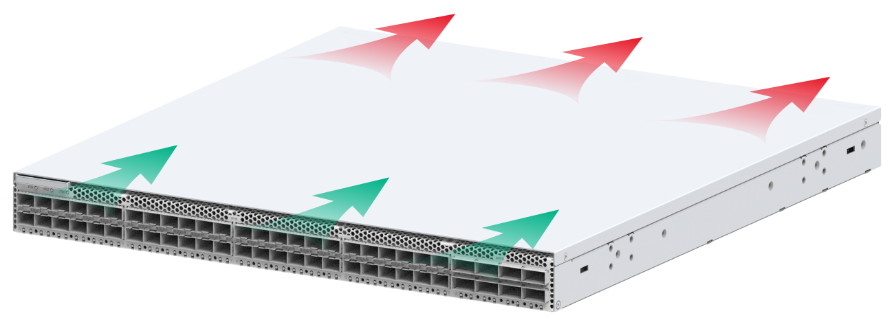
5 Cooling system
|
|
CAUTION: The chassis and power supplies use separate air aisles. Make sure the two aisles are not blocked when the device is operating. |
To dissipate heat timely and ensure system stability, the device uses the front-rear air aisle cooling system. Consider the site ventilation design when you plan the installation site for the device.
Table5-1 Cooling system for the device
|
Device model |
Available fan trays |
Airflow direction |
|
S12500R-48Y8C |
FAN-40B-1-C |
From the port side to the power supply side |
Figure5-1 Airflow from the port side to the power supply side through the chassis