- Table of Contents
- Related Documents
-
| Title | Size | Download |
|---|---|---|
| 04-Slot Arrangment and Interface Numbering | 526.81 KB |
4 Slot arrangment and interface numbering
Slot arrangement for MPUs, switching fabric modules, and service modules
4 Slot arrangment and interface numbering
Slot arrangement
The router provides multiple types of ports, including console port, AUX port, GigabitEthernet port, serial (synchronous) port, POS port, and E1 port.
Figure4-1 Slot arrangement on the SR6604 configured with an RPE-X1/RPE-X3/RPE-X5/RPE-X5E MPU
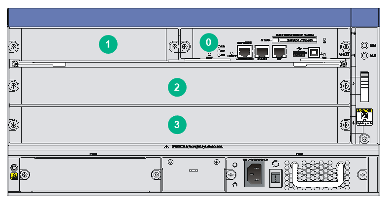
Figure4-2 Slot arrangement on the SR6604 configured with an RSE-X1 or MCP-X1/X2 MPU
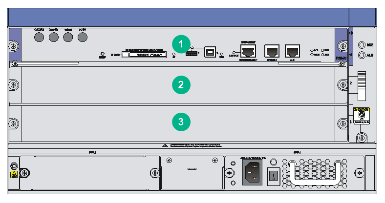
Figure4-3 Slot arrangement on the SR6608 configured with an RPE-X1/RPE-X3/RPE-X5/RPE-X5E MPU
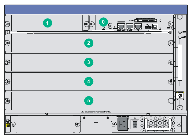
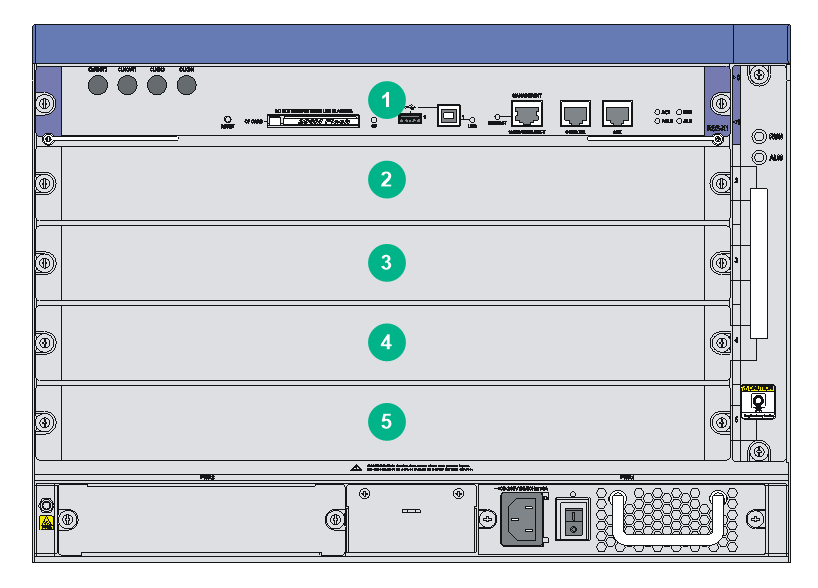
Figure4-4 Slot arrangement on the SR6608 configured with an RSE-X1 or MCP-X1/X2 MPU
|
|
NOTE: · The numbers in Figure4-1 through Figure4-4 represent corresponding slot numbers. · On a router configured with an RSE-X1 or MCP-X1/X2 MPU, the slots are numbered from 1 instead 0. |
Slot arrangement for MPUs, switching fabric modules, and service modules
Table4-1 Slot arrangement for MPUs, switching fabric modules, and service modules
|
MPUs, switching fabric modules, and service modules |
Slot arrangement on the SR6604 |
Slot arrangement on the SR6608 |
|
MPUs |
||
|
RPE-X1/RPE-X3/RPE-X5/RPE-X5E (supporting 1+1 redundancy) |
Slot 0 and slot 1 An SR6608-DS router does not support the RPE-X1 MPU. |
|
|
RSE-X1 (supporting 1+1 redundancy) |
Slot 1 and slot 2 Not supported on an SR6608-DS router. |
|
|
MCP-X1/X2 (supporting 1+1 redundancy) |
Slot 1 and slot 2 Not supported on an SR6608-DS router. |
|
|
Switching fabric modules |
||
|
SFE-L1 |
Slot 2 and slot 3 |
Slot 2 through slot 5 Not supported on an SR6608-DS router. |
|
SFE-L2 |
N/A |
Slot 2 and slot 3 on an SR6608-DS router. (To install the SFE-L2 switching fabric module in slot 3 on an SR6608-DS router, first install a carrier in the slot.) |
|
Service modules |
||
|
FIP-10 FIP-20 FIP-110 FIP-210 FIP-240 FIP-260 FIP-300 FIP-310 FIP-380 FIP-600 FIP-660 FIP-680 SAP/OAP card |
Slot 2 and slot 3 |
· Slot 2 through slot 5 · Slot 3 through slot 5 on an SR6608-DS router |
Numbering interfaces
Before installing a HIM/MIM/MIC/MIC-X, you must install a FIP.
The interfaces of the router are numbered in the form of interface-type X/Y/Z,
Where,
· interface-type—Type of the interface such as GE port and serial port.
· X—Number of the slot where the FIP/SAP resides, in the range of 2 to 3 on the SR6604 and 2 to 5 on the SR6608.
· Y—Number of the slot where the HIM/MIM/MIC/MIC-X resides on the FIP. For a SAP, the subslot number is 0.
· Z—Number of the interface on the HIM/MIM/MIC/MIC-X or on the SAP.
For each interface type on a HIM/MIM/MIC/MIC-X or SAP, the number Z starts from 0.
|
|
NOTE: · Different interface modules on the same FIP have the same slot number. · Different interfaces on the same HIM/MIM/MIC/MIC-X have the same subslot number. |
Examples
Example 1
A MIM-2GBE module is installed on a FIP-110 in slot 3 of the router.
· Fixed GigabitEthernet interfaces 0 and 1 on the FIP-110 are numbered GigabitEthernet 3/0/0 and GigabitEthernet 3/0/1, respectively.
|
|
NOTE: The subslot number Y of fixed GE interfaces on a FIP is 0. |
· If the MIM-2GBE module is installed in slot 1 of the FIP-110, the two GigabitEthernet interfaces 0 and 1 on the MIM-2GBE are numbered GigabitEthernet 3/1/0 and GigabitEthernet 3/1/1, respectively,
· If the MIM-2GBE module is installed in slot 2 of the FIP-110, the two GigabitEthernet interfaces 0 and 1 on the MIM-2GBE are numbered GigabitEthernet 3/2/0 and GigabitEthernet 3/2/1, respectively.
Example 2
A HIM-4GBE module is installed on a FIP-210 in slot 3 of the router.
· The two fixed GigabitEthernet interfaces 0 and 1 on the FIP-210 are numbered GigabitEthernet 3/0/0 and GigabitEthernet 3/0/1, respectively.
· If the HIM-4GBE is installed in slot 1 of the FIP-210, the GigabitEthernet interfaces 0 and 3 on the HIM-4GBE are numbered GigabitEthernet 3/1/0 to GigabitEthernet 3/1/3, respectively.
· If the HIM-4GBE is installed in slot 2 of the FIP-210, the GigabitEthernet interfaces 0 and 3 on the HIM-4GBE are numbered GigabitEthernet 3/2/0 to GigabitEthernet 3/2/3, respectively.
