- Table of Contents
- Related Documents
-
| Title | Size | Download |
|---|---|---|
| 02-Installation Guide | 2.33 MB |
Contents
Examining the installation site
Installing the switch in a 19-inch rack
Attaching the mounting brackets to the switch
Mounting the switch on a workbench
Connecting the Ethernet electric port cables
Connecting the Ethernet optical cables
1 Preparing for installation
Safety recommendations
To avoid any equipment damage or bodily injury caused by incorrect use, read the following safety recommendations before installation. Note that the recommendations do not cover every possible hazardous condition.
· Before cleaning the switch, remove all power cords from the switch. Do not clean the switch with wet cloth or liquid.
· Do not place the switch near water or in a damp environment. Prevent water or moisture from entering the switch chassis.
· Do not place the switch on an unstable case or desk. The switch might be severely damaged in case of a fall.
· Ensure good ventilation of the equipment room and keep the air inlet and outlet vents of the switch free of obstruction.
· Make sure the operating voltage is in the required range.
· To avoid electrical shocks, do not open the chassis while the switch is operating or when the switch is just powered off.
· During the installation, wear a well-grounded ESD wrist strap to avoid damaging the units.
Examining the installation site
The switch must be used indoors. Mount your switch in a rack or on a workbench and verify the following items:
· Adequate clearance is reserved at the air inlet and outlet vents for ventilation.
· The rack and the workbench have a good ventilation system.
· The rack and the workbench are sturdy enough to support the switch and its accessories.
· The rack and the workbench are reliably grounded.
To ensure correct operation and long service life of your switch, install it in an environment that meets the requirements described in the following subsections.
Temperature/Humidity
Maintain appropriate temperature and humidity in the equipment room.
· Lasting high relative humidity can cause poor insulation, electricity leakage, mechanical property change of materials, and metal corrosion.
· Lasting low relative humidity can cause washer contraction and ESD and cause problems including loose mounting screws and circuit failure.
· High temperature can accelerate the aging of insulation materials and significantly lower the reliability and lifespan of the switch.
For the temperature and humidity requirements for the switch, see the hardware information and specifications of the installation guide.
Cleanliness
Dust buildup on the chassis might cause electrostatic adsorption and dust corrosion, resulting in poor contact of metal connectors and contact points. This might shorten the device's lifetime and even cause device failure in the worst case. The dust concentration limit in the equipment room is shown in the table below.
Table1-1 Dust concentration limit in the equipment room
|
Substance |
Unit |
Concentration limit |
|
Dust particle (diameter ≥ 0.5 μm) |
/m³ |
≤ 3.5×10⁶ |
|
Dust particle (diameter ≥ 5 μm) |
/m³ |
≤ 3×10⁴ |
|
Suspending dust (diameter ≤ 75 μm) |
mg/m³ |
0.2 |
|
Descending dust (75 μm ≤ diameter ≤ 150 μm) |
mg/(m2h) |
1.5 |
To maintain cleanliness in the equipment room, follow these guidelines:
· Keep the equipment room away from pollution sources. Do not smoke, eat, or drink in the equipment room.
· Use double-layer glass in windows and seal doors and windows with dust-proof rubber strips. Use screen doors and window screens for doors and windows open to the outside and make sure the external windows are air tight.
· Use dustproof materials for floors, walls, and ceilings and use wallpaper or matt paint that does not produce powders.
· Clean the equipment room regularly and clean the air filters of the rack each month.
· Wear ESD clothing and shoe covers before entering the equipment room, keep the ESD clothing and shoe covers clean, and change them frequently.
Corrosive gas limit
Corrosive gases can accelerate corrosion and aging of metal components. Make sure the corrosive gases do not exceed the concentration limits as shown in the table below.
Table1-2 Corrosive gas concentration limits
|
Gas |
Average concentration (mg/m³) |
Maximum concentration (mg/m3) |
|
SO2 |
0.3 |
1.0 |
|
H2S |
0.1 |
0.5 |
|
Cl2 |
0.1 |
0.3 |
|
HCI |
0.1 |
0.5 |
|
HF |
0.01 |
0.03 |
|
NH3 |
1.0 |
3.0 |
|
O3 |
0.05 |
0.1 |
|
NOx |
0.5 |
1.0 |
|
Caution: The average concentration is a long-term value and the maximum concentration is the peak or limit value. Make sure the corrosive gas concentrations do not exceed 30 minutes per day at their maximum values. |
||
To maintain cleanliness in the equipment room, follow these guidelines:
· As a best practice, do not build the equipment room in a place with a high concentration of corrosive gases.
· Make sure the equipment room is not connected to sewer, vertical shaft, or septic tank pipelines and keep it far away from these pipelines. The air inlet of the equipment room must be away from such pollution sources.
· Use environmentally friendly materials to decorate the equipment room. Avoid using organic materials that contains harmful gases, such as sulfur or chlorine-containing insulation cottons, rubber mats, sound-proof cottons, and avoid using plasterboards with high sulfur concentration.
· Place fuel (diesel or gasoline) engines separately. Do not place them in the same equipment room with the device. Make sure the exhausted air of the engines will not flow into the equipment room or towards the air inlet of the air conditioners.
· Place batteries separately. Do not place them in the same room with the device.
· Employ a professional company to monitor and control corrosive gases in the equipment room regularly.
EMI
All electromagnetic interference (EMI) sources, from outside or inside of the switch and application system, adversely affect the switch in the following ways:
· A conduction pattern of capacitance coupling.
· Inductance coupling.
· Electromagnetic wave radiation.
· Common impedance (including the grounding system) coupling. To prevent EMI, use the following guidelines:
¡ If AC power is used, use a single-phase three-wire power receptacle with protection earth (PE) to filter interference from the power grid.
¡ Keep the switch far away from radio transmitting stations, radar stations, and high-frequency devices.
¡ Use electromagnetic shielding, for example, shielded interface cables, when necessary.
¡ To prevent signal ports from getting damaged by overvoltage or overcurrent caused by lightning strikes, route interface cables only indoors.
Laser safety
The switch is a Class 1 laser device.
|
|
WARNING! Disconnected optical fibers or transceiver modules might emit invisible laser light. Do not stare into beams or view directly with optical instruments when the switch is operating. |
Package contents
Table1-3 Package contents
|
S/N |
Item |
Quantity |
Description |
|
1 |
Switch |
1 |
- |
|
2 |
Power cord |
1 |
1.5 m (59.05 in) |
|
3 |
Mounting brackets |
2 |
· For equipment at the width of 294 mm (11.57 in): 95×25×43.6 mm (3.74×0.98×1.72 in) · For equipment at the width of 440 mm (17.32 in): 39×21×43.6 mm (1.54×0.83×1.72 in) |
|
4 |
Rubber foot |
4 |
Φ13×4.5 mm (0.18 in) |
|
5 |
Screw |
1 |
· For equipment at the width of 294 mm (11.57 in): M4×6 mm (0.24 in), four · For equipment at the width of 440 mm (17.32 in): M3×6 mm (0.24 in), eight |
|
6 |
All-in-one document (including the warranty card) |
1 |
- |
|
7 |
Compliance and safety information |
1 |
- |
Installation tools
· ESD wrist strap.
· Phillips screwdriver.
· Nipper pliers
· Diagonal pliers
|
|
WARNING! No installation tools are provided with the switch. Prepare the following tools yourself. |
2 Installing the switch
Installing the switch in a 19-inch rack
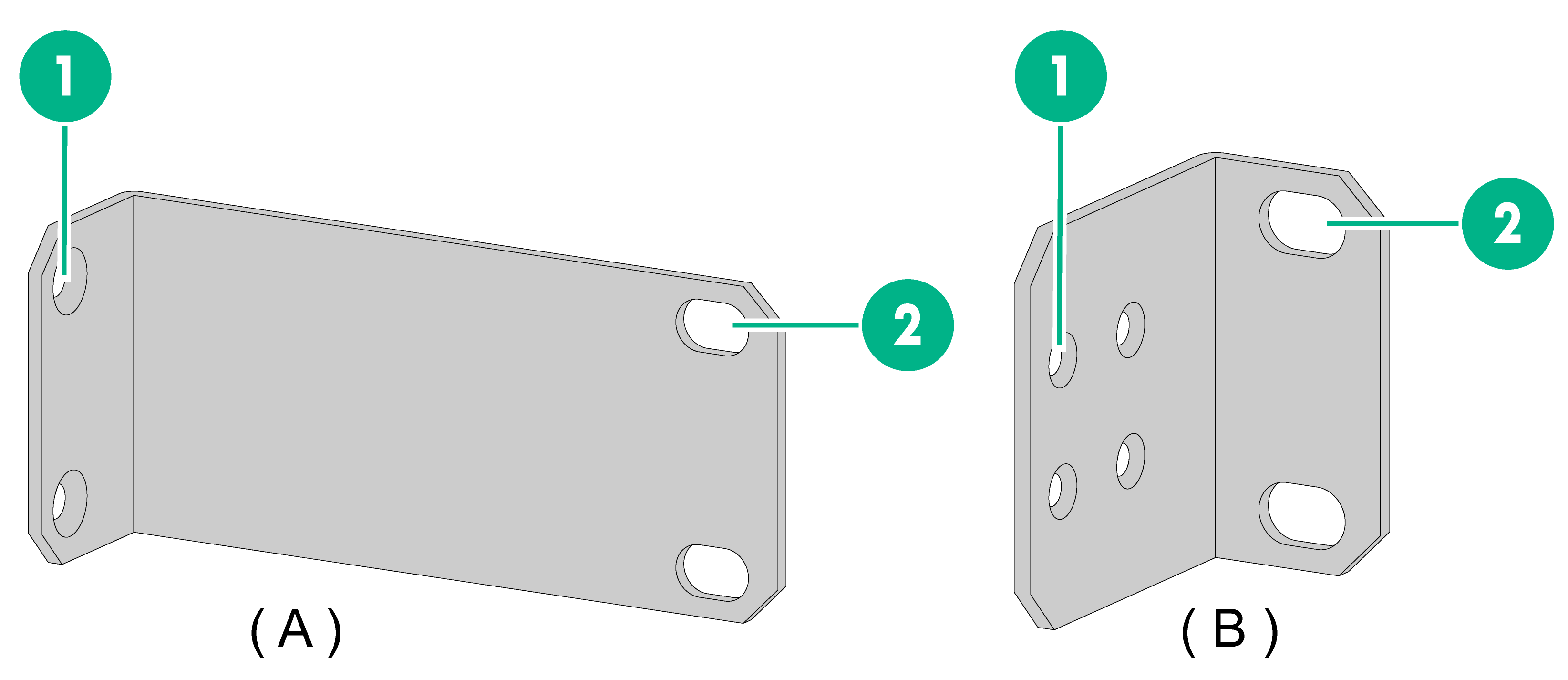
Mounting brackets
Table2-1 Mounting brackets applicable to the switch
|
Switch model |
Mounting brackets |
Description |
|
BS216 BS224 |
Mounting bracket A (provided) |
See A in Figure2-1 |
|
BS218F-HP |
Mounting bracket B (provided) |
See B in Figure2-1 |
|
(1) Screw hole for attaching the bracket to the switch |
(2) Screw hole for attaching the bracket to the rack post |
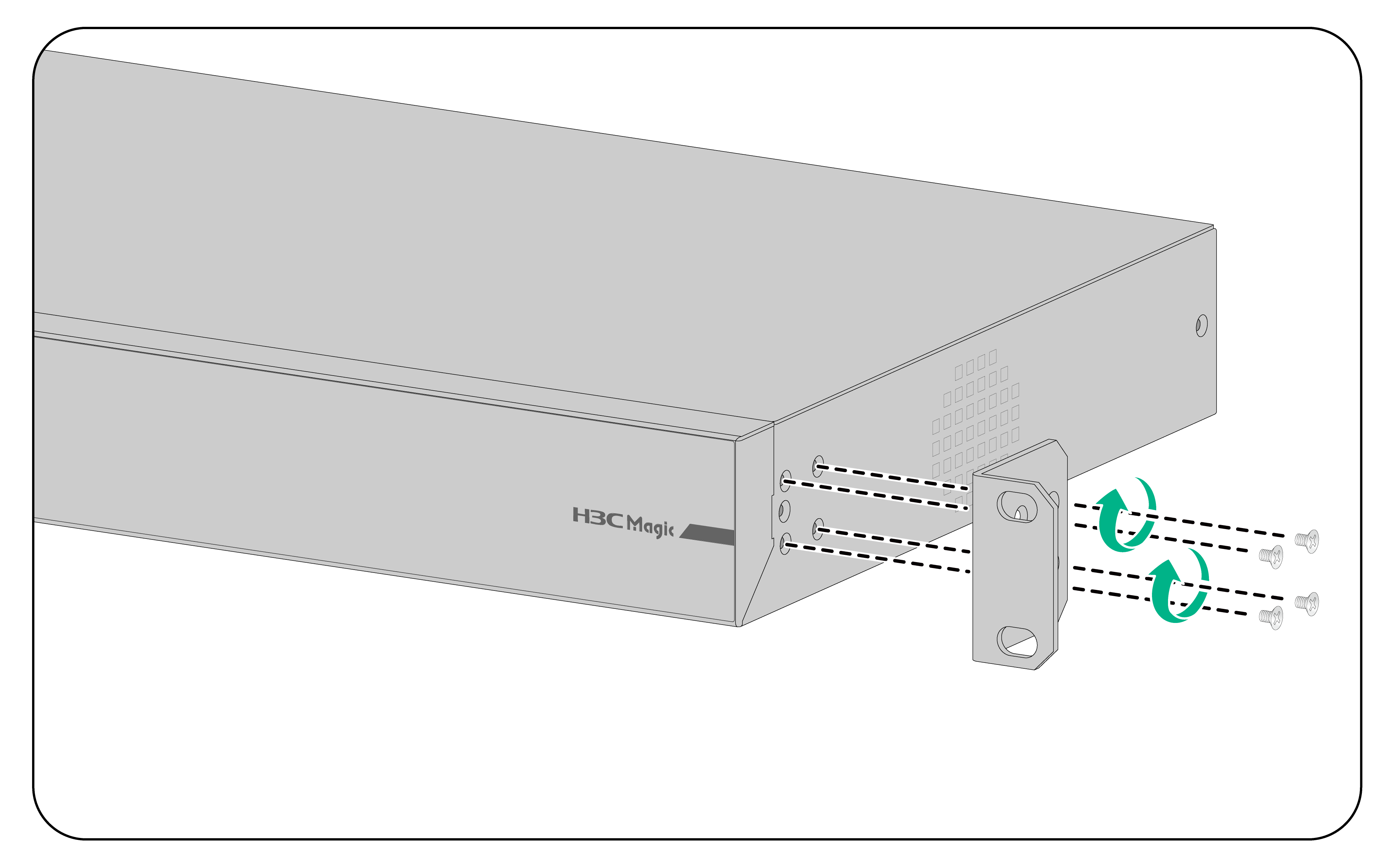
Attaching the mounting brackets to the switch
Align one mounting bracket with the screw holes at the mounting position. Use screws to attach the mounting bracket to the chassis. See Figure2-2 for installing mounting bracket A, and Figure2-3 for installing mounting bracket B
|
|
NOTE: Repeat step 1 to attach the other mounting bracket to the chassis. |
Figure2-2 Attaching mounting bracket A (BS216 switch)
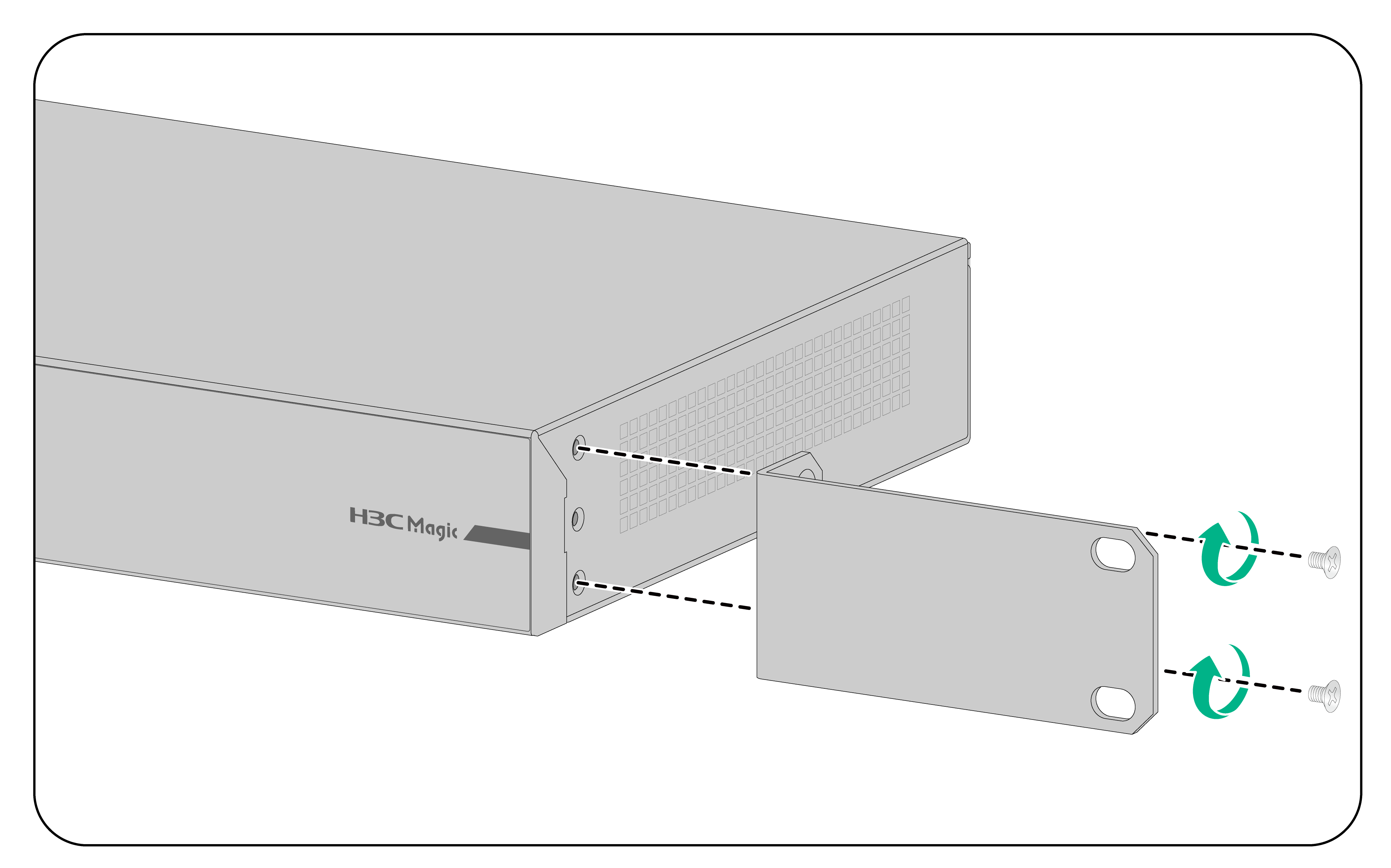
Figure2-3 Attaching mounting bracket B (BS218F-HP switch)
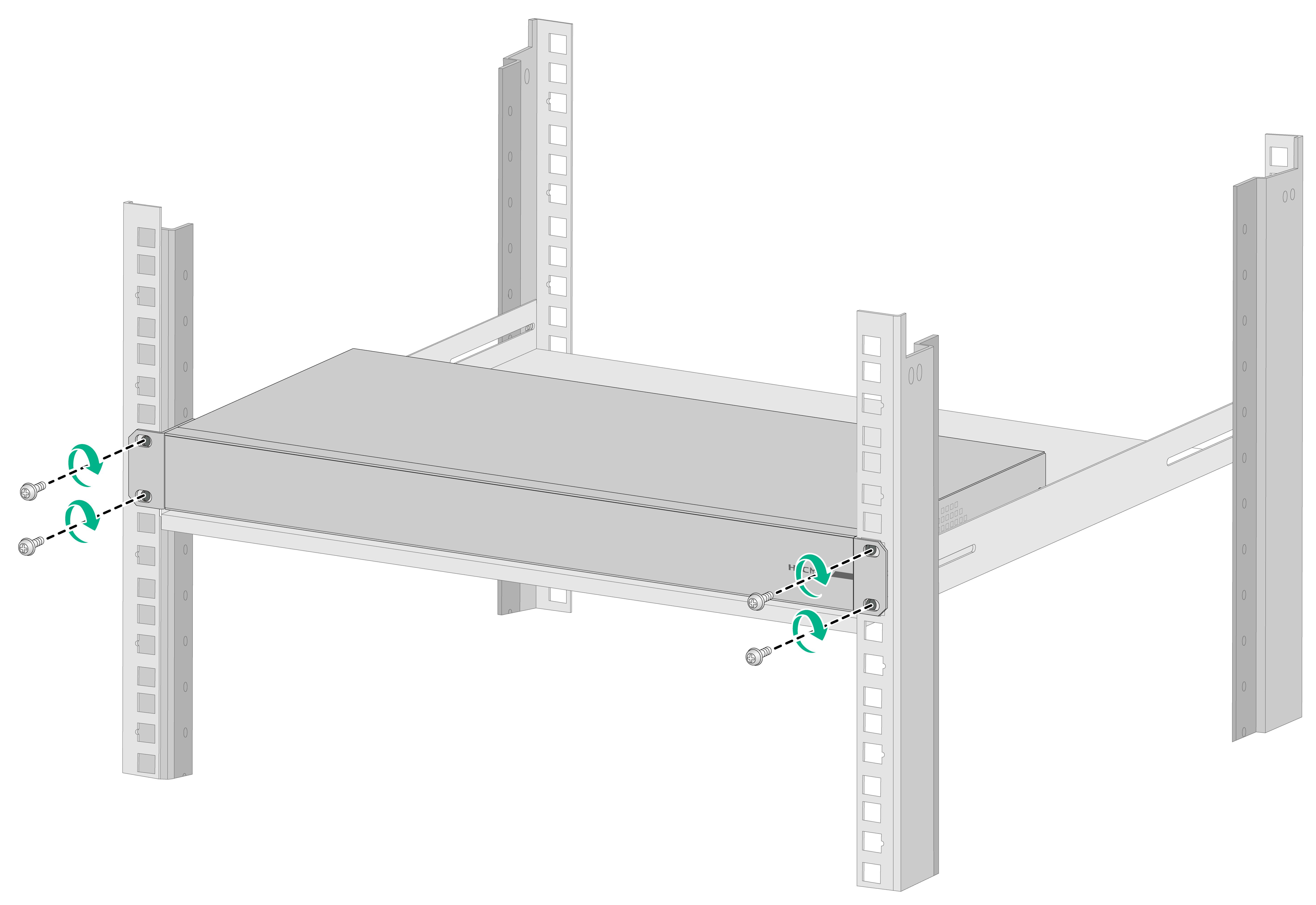
Rack-mounting the switch
|
|
NOTE: The mounting brackets are for fixation, instead of weight bearing. A rack is required to be fixed under the chassis for support during installation. |
1. Wear an ESD wrist strap. Make sure it makes good skin contact and is reliably grounded.
2. Verify that the mounting brackets have been securely attached to the switch chassis.
3. Install cage nuts in the mounting holes in the rack posts. Make sure the nuts on both sides are on the same water level. (No cage nuts are provided with the switch. Prepare them yourself.)
4. Place the switch chassis and aligns the mounting brackets with the mounting holes in the rack posts.
5. Attaches the mounting brackets to the rack with M6×12 mm screws and verify that the switch chassis is horizontal and secure. (No M6×12 mm screws are provided with the switch. Prepare them yourself.)
Figure2-4 Mounting a BS216 switch in the rack
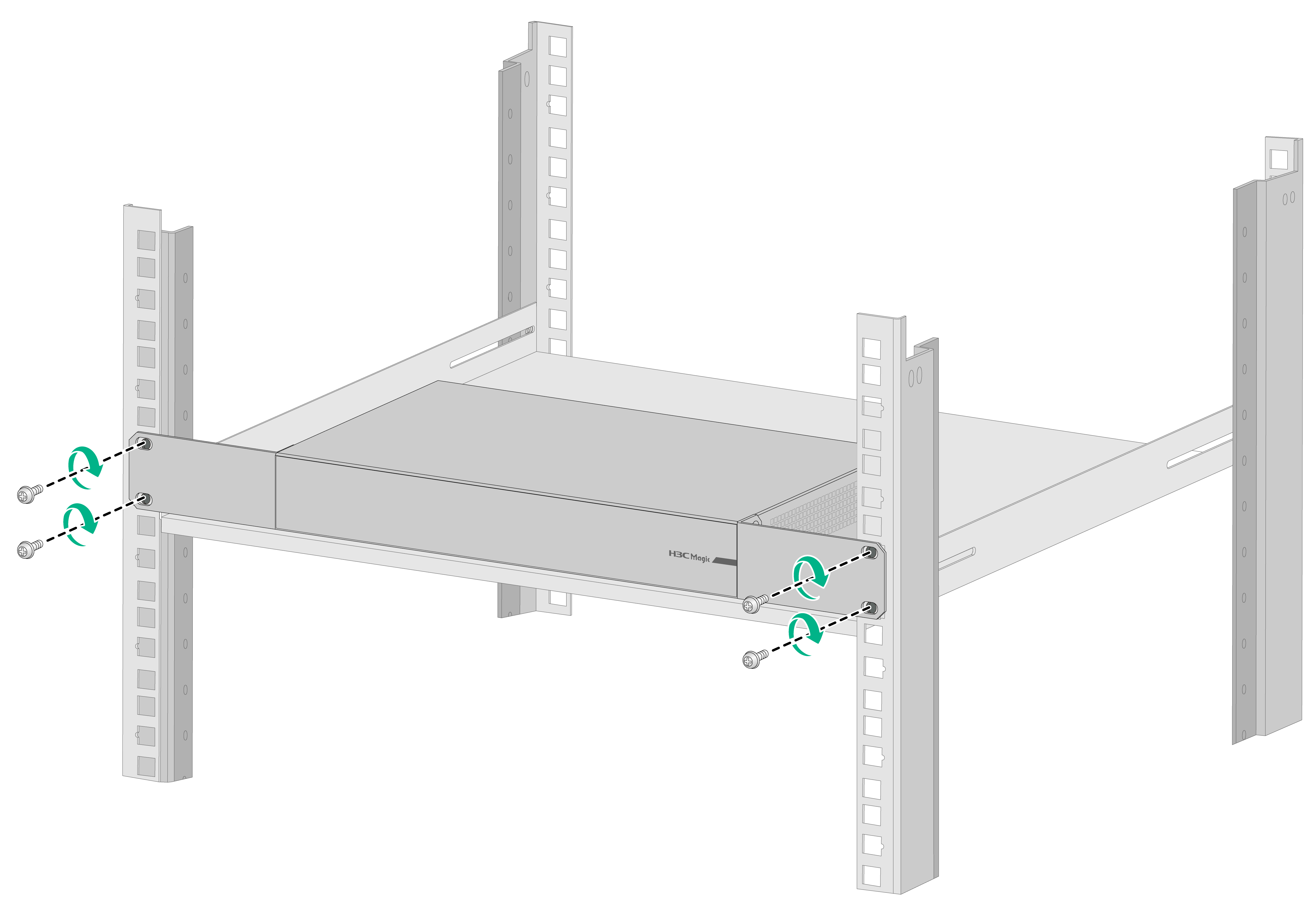
Figure2-5 Mounting a BS218F-HP switch in the rack
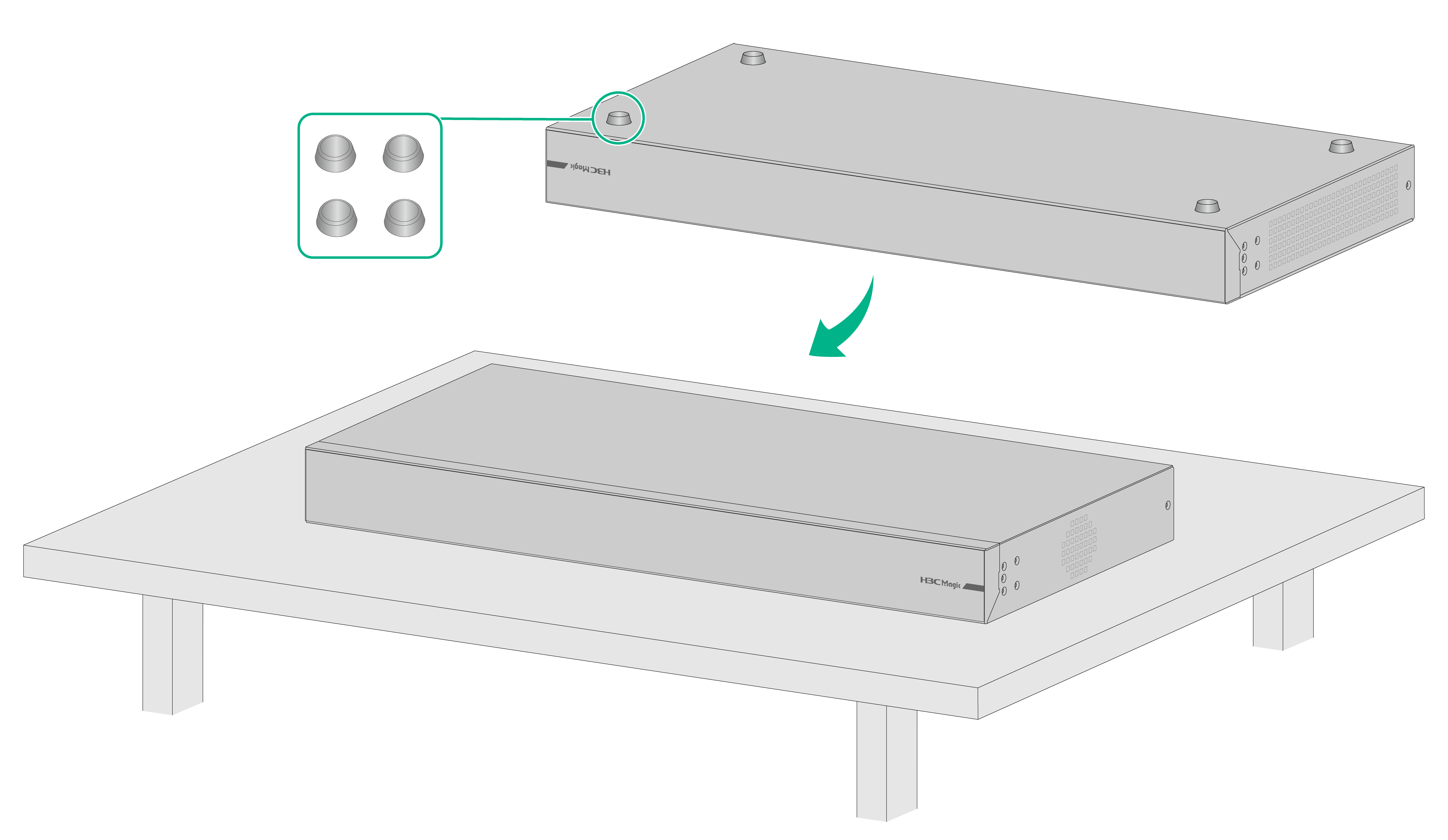
Mounting the switch on a workbench
If a standard 19-inch rack is not available, you can place you switch on a workbench. To mount the switch on a workbench:
1. Place the switch with bottom up. Clean the round holes in the chassis bottom with dry cloth.
2. Attach the rubber feet to the four round holes in the chassis bottom.
3. Place the switch with upside up on the workbench.
Figure2-6 Mounting the switch on a workbench
Following the guidelines:
· Verify that the workbench is sturdy and reliably grounded.
· Ensure 10 cm (3.94 in) of clearance around the chassis for heat dissipation.
· Do not place heavy objects on the switch.
Grounding the switch
|
|
WARNING! · Correctly connecting the switch grounding cable is crucial to lightning protection, ESD, and EMI protection. · Connect the grounding cable to the grounding system in the equipment room. Do not connect it to a fire main or lightning rod. · The chassis power supply and grounding terminal positions in the following figures are for illustration only. · The grounding cables are not provided with the switch. Prepare them yourself. |
The power input of the switch is connected to a noise filter, and its center grounding is directly connected to the switch, called the chassis ground (i.e., protection ground). This chassis ground must be well grounded, in order to make induced electricity and leaked electricity can safely flow into the earth, improving the electromagnetic immunity of the switch.
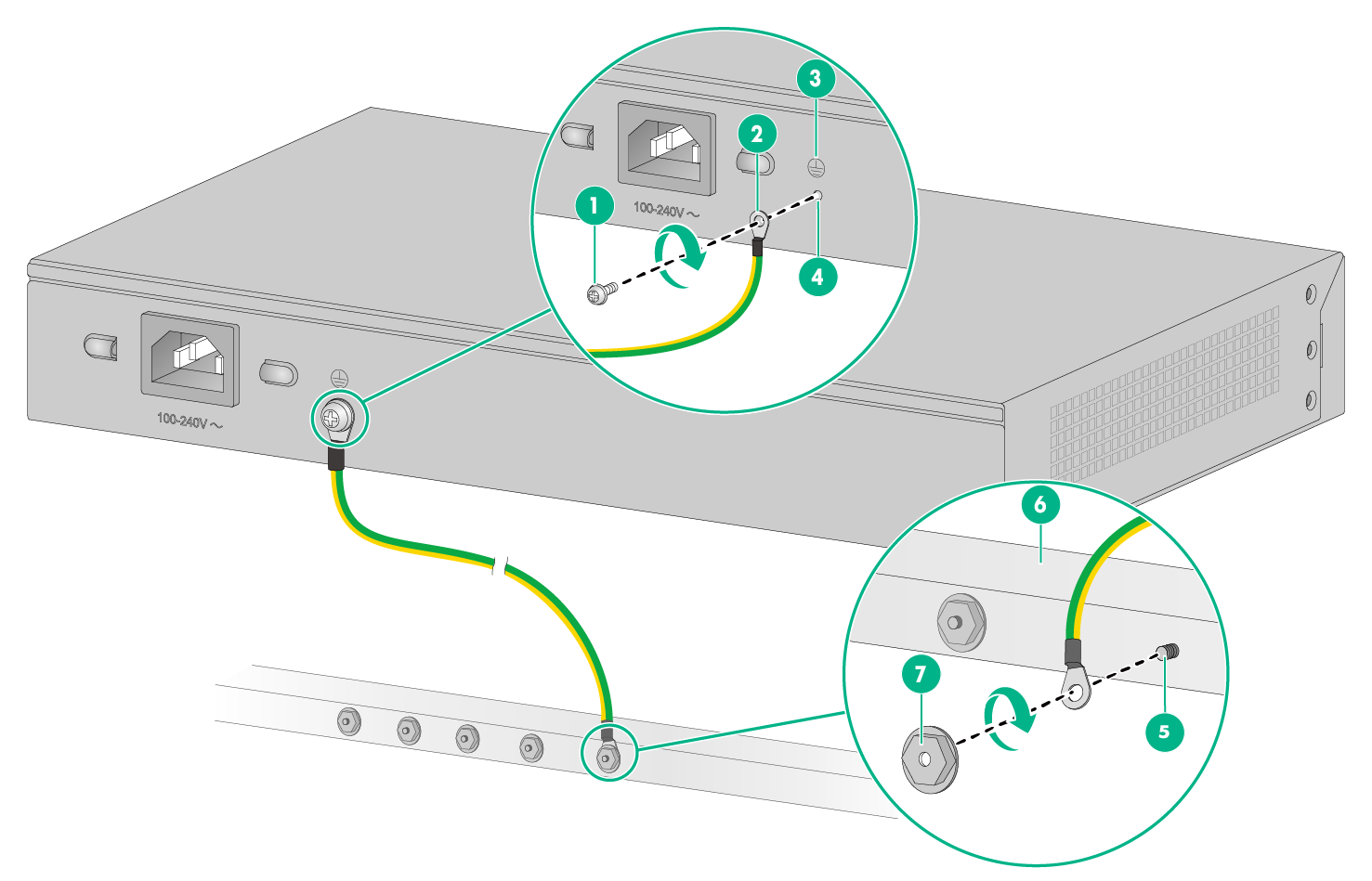
1. Attach the ring terminal end of the grounding cable to the grounding hole in the switch:
Remove the grounding screw from the grounding hole in the rear panel of the switch.
Attach the grounding screw to the ring terminal of the grounding cable.
Use a screwdriver to fasten the grounding screw into the grounding screw hole.
2. Connect the other end of the grounding cable to the grounding strip. And use the hex nut to secure the cable to the post.
Figure2-7 Attaching the grounding cable to the grounding hole of the switch (BS216 switch)
|
(1): Grounding screw |
(2): Ring terminal |
|
(3): Grounding sign |
(4): Grounding hole |
|
(5): Grounding post |
(6): Grounding strip |
|
(7): Hex nut |
|
Connecting the port cables
Connecting the Ethernet electric port cables
1. Connect one end of the Ethernet cable to the Ethernet port on the switch, and the other end to the Ethernet port of the other device. Ethernet electric port supports MDI/MDIX self-adaptive.
2. Power on and verify that the LEDs of the Ethernet ports are normal. For the status of the indicators, see LEDs in Hardware Introduction and Specifications.
Connecting the Ethernet optical cables
|
|
CAUTION: · The radius of curvature of optical cables shall not be smaller than 100 mm. Do not bend. · Maintain the cleanliness of the ends on the optical cables. · Confirm that the types of the selected optical cable connectors and modules match. · Install the optical module and the optical cables. Do not insert the optical cables directly to the optical port. |
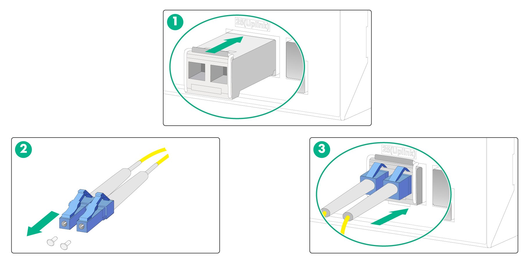
To install the optical cables:
1. Wear an ESD wrist strap. Make sure the handle of the optical module flips up vertically and locks in the top buckle. Pinch the sides of the optical module with your hands and slowly insert the end without the handle into the optical slot.
2. Verify the Rx and Tx ports on the optical module and remove the protection cap on the optical cable.
3. Plug the two LC-type connectors at one end of the cable into the Rx and Tx ports respectively. Plug the two LC-type connectors at the other end of the fiber into the Tx and Rx ports of the other device respectively.
4. Power on and verify that the LEDs on the panel are normal:
¡ On - The link is present on the port.
¡ Off - The link is not present. The sending port and the receiving port might be connected wrong. Exchange the Rx and Tx ports on the optical cable.
|
WARNING! Do not stare into the optical port and optical cable connectors to prevent the beam from hurting your eyes. |
Figure2-8 Install the optical module and optical cables.
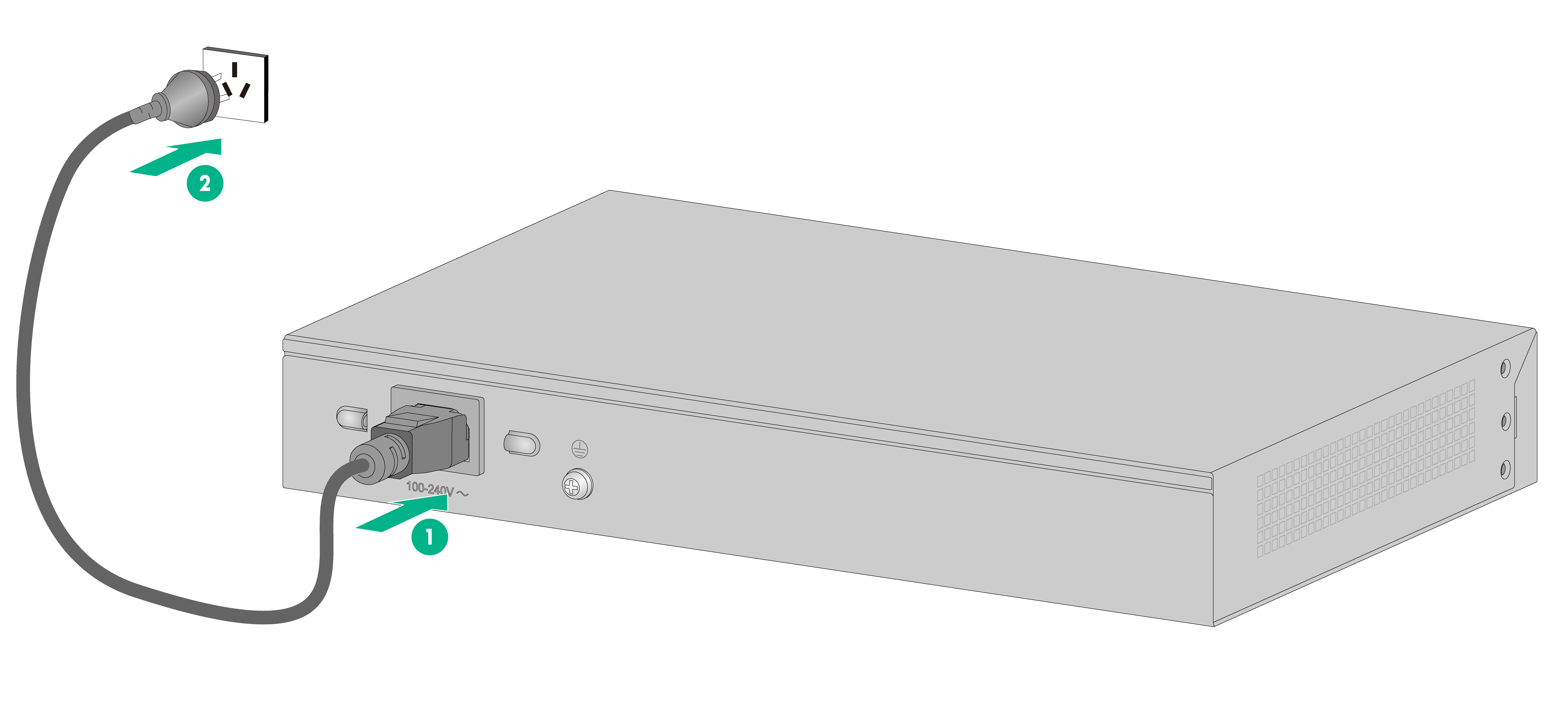
Connecting the AC power cord
1. Wear an ESD wrist strap. Make sure it makes good skin contact and is reliably grounded.
2. Plug the end of the AC power cord of the switch with the socket into the power input connector of the switch.
3. Connect the other end of the power cord to an external AC socket.
Figure2-9 Connect the AC power cord
Verifying the installation
After you complete the installation, verify that:
· There is enough space for heat dissipation around the switch, and the rack or workbench is stable.
· The grounding cable is securely connected.
· The power cords are securely and correctly connected.
· All the interface cables are routed indoors. If any cable is routed outdoors, verify that the socket strip with lightning protection and lightning arresters for network ports have been correctly connected.
3 Troubleshooting
This documentation provides some regular for troubleshooting. If any fault persists, contact H3C customer support.
|
Fault |
Troubleshooting |
|
Power LED off |
1. Verify that the power cords are correctly connected. 2. Verify that the power supply is on. |
|
LAN interface LED off |
1. Verify that the network cable is securely inserted in the Ethernet port. 2. Plug both ends of the cable into the two Ethernet ports of the switch. If both LEDs of the ports are on, the cable is not defected; otherwise replace the cable and try again. |
|
Restore the factory settings |
Use the function button: With the switch powered on, press and hold the function button for 10 seconds. When four operation mode LEDs are on at the same time, the switch is then restored to the factory settings. |