- Table of Contents
- Related Documents
-
| Title | Size | Download |
|---|---|---|
| 01-Hardware Information and Specifications | 692.21 KB |
1 Introduction
Overview
H3C Magic BS200 Switch Series (hereinafter referred to as BS200) are a portfolio of GE cloud-managed network switches.
The switch, adopting a brand new software and hardware platform, supports one-key switching among four operating modes (standard switch, port isolation, uplink aggregation, and network clone), providing an effective response to a variety of complex network environments. The switch, featuring easy installation and abundant service features, also can be managed and maintained in a unified manner through a cloud network (cloud + gateway), making it applicable to small and micro enterprises, commercial chains, hotels, and campuses.
Product models
Table1-1 describes the models of the BS200 Ethernet switch series.
|
Series |
Model |
Short name |
|
|
Magic BS200 series |
Non-PoE switch models |
H3C Magic BS216 |
BS216 |
|
H3C Magic BS224 |
BS224 |
||
|
PoE switch models |
H3C Magic BS218F-HP |
BS218F-HP |
|
Technical specifications
Table1-2 Technical specifications for non-PoE switch models of Magic BS200 Ethernet Switch Series
|
Item |
BS216 |
BS224 |
|
Dimensions (H × W × D) |
294 × 179 × 43.6 mm (11.57 × 7.05 × 1.72 in) |
|
|
Weight |
≤ 1.3 kg (2.87 lb) |
|
|
10/100/1000BASE-T autosensing Ethernet port |
16 (including 2 Uplink ports) |
24 (including 2 Uplink ports) |
|
Input voltage |
100 V to 240 V AC, 50 or 60 Hz |
|
|
Minimum power consumption |
7.8 W |
|
|
Maximum power consumption |
≤ 11 W |
≤ 16.5 W |
|
Working mode |
Supporting 4 operating models, including standard, isolation, aggregation, and clone |
|
|
Cooling system |
Natural cooling |
|
|
Chassis leakage current compliance |
EN/IEC 62368-1 |
|
|
Operating temperature |
0°C to 40°C (32°F to 104°F) |
|
|
Operating humidity |
5% to 95%, noncondensing |
|
|
Fire resistance compliance |
EN/IEC 62368-1 |
|
Table1-3 Technical specifications for PoE switch models of Magic BS200 Ethernet Switch Series
|
Item |
BS218F-HP |
|
Dimensions (H × W × D) |
440 × 210 × 43.6 mm (17.32 × 8.27 × 1.72 in) |
|
Weight |
≤ 2.4 kg (5.29 lb) |
|
10/100/1000BASE-T autosensing Ethernet port |
16 (including 2 Uplink ports) |
|
1000Base-X SFP port |
2 (Uplink ports) |
|
Input voltage |
100 V to 240 V AC, 50 or 60 Hz |
|
Maximum PoE power per port |
30 W |
|
Total PoE power |
225 W |
|
Minimum power consumption |
20 W |
|
Maximum power consumption (including PoE power consumption) |
≤ 255 W (including 225 W total PoE power) |
|
Working mode |
Supporting 4 operating models, including standard, isolation, aggregation, and clone |
|
Cooling system |
Cooling with fan |
|
Chassis leakage current compliance |
EN/IEC 62368-1 |
|
Operating temperature |
0°C to 40°C (32°F to 104°F) |
|
Operating humidity |
5% to 95%, noncondensing |
|
Fire resistance compliance |
EN/IEC 62368-1 |
2 Chassis view
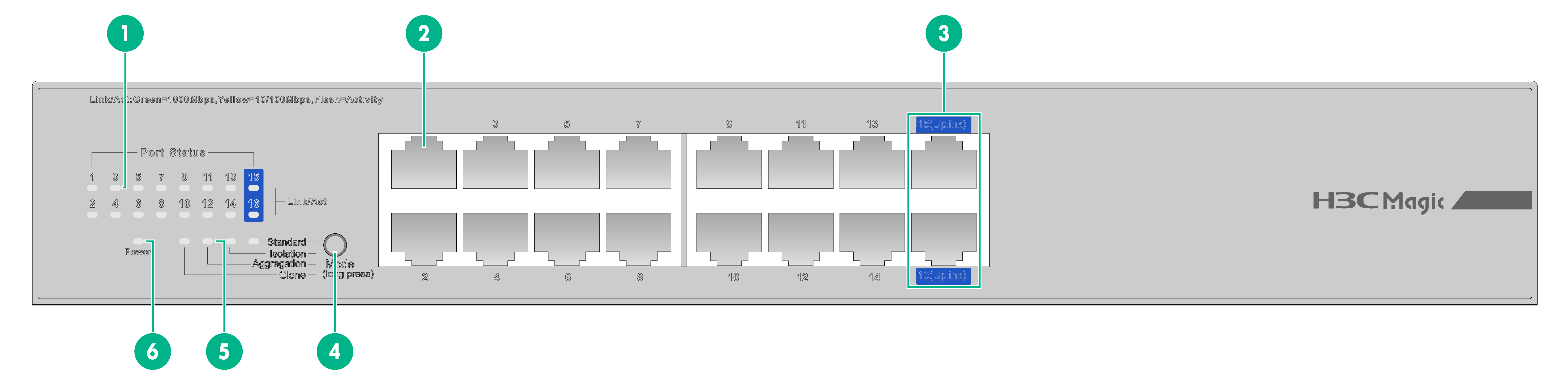
BS216 switch
|
(1): Ethernet port LED |
(2): 10/100/1000Base-T Ethernet port |
|
(3): 10/100/1000Base-T Ethernet port (Uplink port) |
(4): Function key |
|
(5): Mode LED |
(6): Power status LED (Power) |
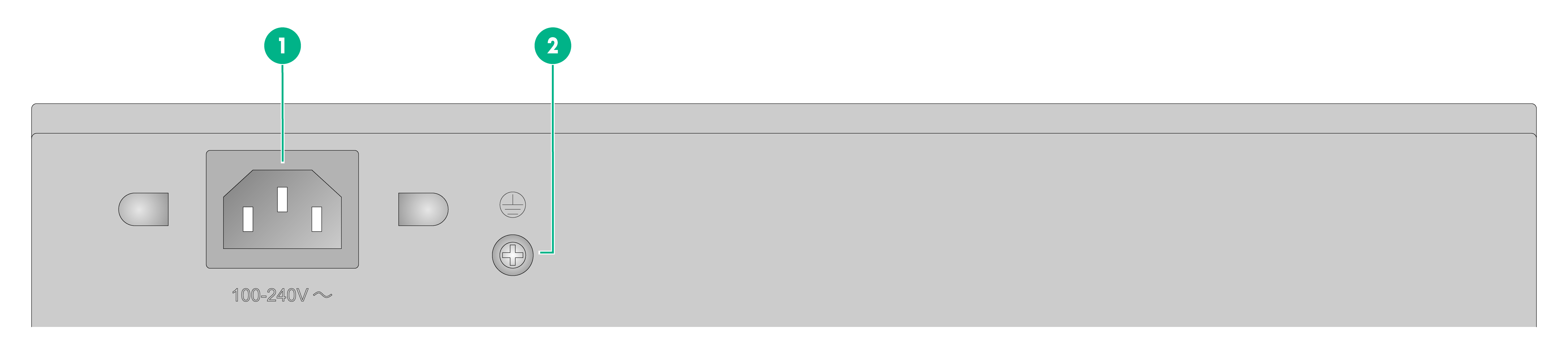
Figure2-2 BS216 rear panel
|
(1): AC-input power receptacle |
(2): Grounding screw |
BS218F-HP switch
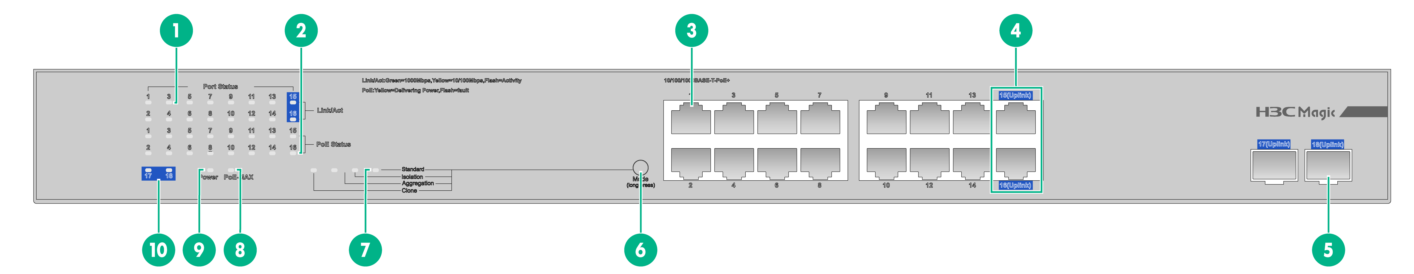
Figure2-3 BS218F-HP front panel
|
(1): Ethernet port LED |
(2): PoE status LED |
|
(3): 10/100/1000Base-T Ethernet port |
(4): 10/100/1000Base-T Ethernet port (Uplink port) |
|
(5): 1000Base-X SFP optical port (Uplink port) |
(6): Function key |
|
(7): Mode LED |
(8): PoE MAX status LED |
|
(9): Power status LED (Power) |
(10): Optical port status LED |
Figure2-4 BS218F-HP rear panel

|
(1): AC-input power receptacle |
(2): Grounding screw |
BS224 switch
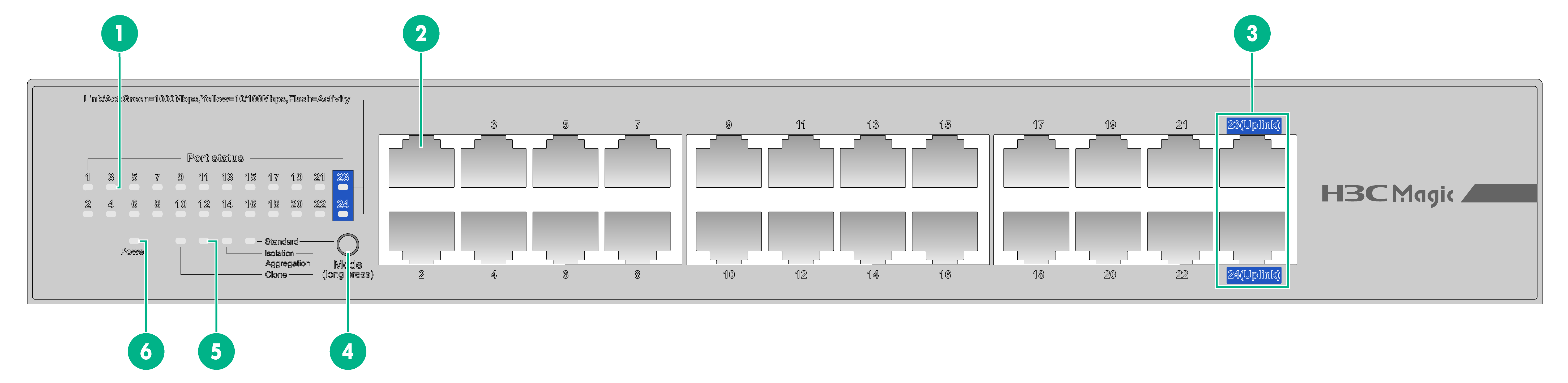
Figure2-5 BS224 front panel
|
(1): Ethernet port LED |
(2): 10/100/1000Base-T Ethernet port |
|
(3): 10/100/1000Base-T Ethernet port (Uplink port) |
(4): Function key |
|
(5): Mode LED |
(6): Power status LED (Power) |
Figure2-6 BS224 rear panel

|
(1): AC-input power receptacle |
(2): Grounding screw |
3 Ports and LEDs
Ports
Function key
The switch series provide a function key for selecting one operating mode among the 4 operating modes. The default operating mode is "standard switch".
Operation instructions
The function key employs an anti-miscontact design. Table3-1 describes the instructions for using the function key.
Table3-1 Operation instructions
|
Operation |
Description |
|
Unlock button |
Press and hold the function key for 3 seconds to unlock the function key. Then, the mode LED flashes. |
|
Mode switch/taking effect |
After the function key is unlocked, press it once to switch to another operating mode. After the function key is pressed, a corresponding mode LED is on. The mode is selected when 5 seconds elapse after the function key is pressed. In this case, the mode LED becomes steady, the mode takes effect, and the function key becomes locked again. |
|
Factory reset |
Press and hold the function key for more than 10 seconds until the 4 mode LEDs are on. In this case, the device will restore its factory setting and automatically reboot. |
Mode description
Table3-2 describes the 4 operating modes.
|
Working mode |
Description |
Application |
|
Standard switch |
Enable traffic control and port negotiation. |
Serve as one standard full GE switch. |
|
Port isolation |
Enable layer-2 isolation between downlink ports so that each port can communicate only with its Uplink ports. |
Apply to scenarios with high privacy requirements for downlink network, reduce broadcasting storms, and isolate DHCP broadcasting. For example, isolate hosts in an Internet cafe. |
|
Uplink aggregation |
Enable traffic control and port negotiation, and provide port trunking for 2 Uplink optical ports or 2 Uplink electrical ports (source MAC + target MAC, static trunking). WARNING! In this case, the peer device port of the Uplink port also requires static trunking. Otherwise, a loop may occur. |
Apply to the requirements for expanding bandwidth when the network bandwidth is inadequate, without replacing a device. |
|
Network clone |
Disable traffic control, but enable port negotiation. |
Apply to the "network clone" application scenario mode. |
|
|
NOTE: · Traffic control: When a local port receives a packet that is faster than a line speed from a remote end, the local port will automatically send flow control frames to the remote port to request the remote port to reduce the transmitting speed, thus ensuring proper communication. · Port negotiation: Negotiate on the transmitting speed before communication, to keep the speed consistent between the two ports. The port speed of the local device can be reduced by enabling port negotiation when it is higher than that of the remote port, to ensure proper communication. · Port trunking: Static trunking is applied for the two Uplink ports to form a trunking group, in which each port undertake loads based on source MAC + target MAC of received data. |
10/100/1000BASE-T Ethernet port
The Ethernet switch series provide 10/100/1000BASE-T autosensing Ethernet ports. Each device provides two 10/100/1000Base-T Ethernet ports (Uplink ports) as its uplink interfaces.
Table3-3 describes the specifications of the 10/100/1000BASE-T Ethernet port.
Table3-3 Specifications of the 10/100/1000BASE-T Ethernet port
|
Item |
Description |
|
Connector type |
RJ-45 |
|
Specification |
· 10 Mbit/s, half/full duplex · 100 Mbit/s, half/full duplex · 1,000 Mbit/s, full duplex · MDI/MDI-X autosensing |
|
Maximum transmission distance |
100 m |
|
Transmission medium |
Category-5 (or above) twisted pair cable |
|
Compatible standards |
IEEE 802.3i, 802.3u, 802.3ab |
SFP optical port
Some models of the switch series provide SFP ports which support GE SFP transceiver modules or GE SFP cables listed in Table3-4.
Table3-4 GE SFP transceiver modules and cables
|
Transceiver module |
Module name |
Center wavelength |
Connector |
Cable specifications |
Maximum Transmission Distance |
|
GE SFP transceiver module |
1000BASE-SX-SFP |
850nm |
LC |
50/125µm multi-mode fiber |
550 m |
|
62.5/125µm multi-mode fiber |
275 m |
||||
|
1000BASE-LX-SFP |
1310 nm |
LC |
9/125µm single-mode fiber |
10 km |
|
|
1000BASE-LH-SFP |
40 km |
||||
|
1000BASE-ZX-LR-SFP |
1550nm |
LC |
9/125µm single-mode fiber |
40 km |
|
|
1000BASE-ZX-VR-SFP |
70 km |
|
|
NOTE: · H3C SFP transceiver modules and cables are recommended. · The H3C SFP transceiver modules and cables available for the SFP ports are subject to change over time. For the most up-to-date list of H3C SFP transceiver modules and cables available for the SFP ports, contact your H3C sales representative or technical support engineer. |
LEDs
Power status LED
The power status LED shows the operating status of the switch. See Table3-5 for more information.
Table3-5 Power status LED description
|
LED mark |
Status |
Description |
|
Steady green |
The switch has been powered on, and the power module operates properly. |
|
|
Flashing green |
The switch is powering on and self-checking. |
|
|
Off |
The switch is powered off or the power module has failed. |
Mode LED
The 4 mode LEDs show the current operating mode of the device. See Table3-6 for more information.
Table3-6 Description for the mode LED
|
LED mark |
Status |
Description |
|
Standard Isolation Aggregation Clone |
Steady green |
The mode has taken effect. |
|
Flashing green |
The operating mode is being selected. |
|
|
Off |
The mode hasn't taken effect. |
10/100/1000BASE-T Ethernet port LED
Each Ethernet port of one switch has an LED, the Link/Act LED. Table3-7 describes the Link/Act LED.
Table3-7 10/100/1000BASE-T Ethernet port LED
|
LED mark |
Status |
Description |
|
Link/Act |
Steady green |
The port is operating at 1,000 Mbps. The port is properly connected to a remote device. |
|
Flashing green |
The port, operating at 1,000 Mbps, is receiving/sending data. |
|
|
Steady yellow |
The port, operating at 10/100 Mbps, is properly connected to a remote device. |
|
|
Flashing yellow |
The port, operating at 10/100Mbps, is receiving/sending data. |
|
|
Off |
The port is not connected to a remote device or the port connection has failed. |
SFP optical port status LED
Some models of the switch series provide SFP optical ports. Table3-8 describes the SFP optical port status LEDs.
Table3-8 SFP optical interface status LED
|
Switch model |
Status |
Description |
|
BS218F-HP |
Steady green |
The port, operating at 1,000 Mbps, is properly connected to a remote device. |
|
Flashing green |
The port, operating at 1,000 Mbps, is receiving/sending data. |
|
|
Off |
The port is not connected to a remote device or the port connection has failed. |
PoE status LED
Some PoE models of the switch series provide PoE status LEDs. Table3-9 describes the PoE status LEDs.
|
Switch model |
LED mark |
Status |
Description |
|
BS218F-HP |
PoE status |
Steady yellow |
Power supply to a remote device is proper. |
|
Flashing yellow |
Power supply to a remote device is improper. |
||
|
Off |
No power supply to a remote device. |
PoE MAX status LED
Some PoE models of the switch series provide PoE MAX LEDs. Table3-10 describes the PoE MAX LED.
|
Switch model |
LED mark |
Status |
Description |
|
BS218F-HP |
PoE-MAX |
Steady yellow |
The power is within its protection power range: · The BS218F-HP protection power ranges from 205 W to 225 W. |
|
Off |
The power does not reach the lower limit of the protection power range. |
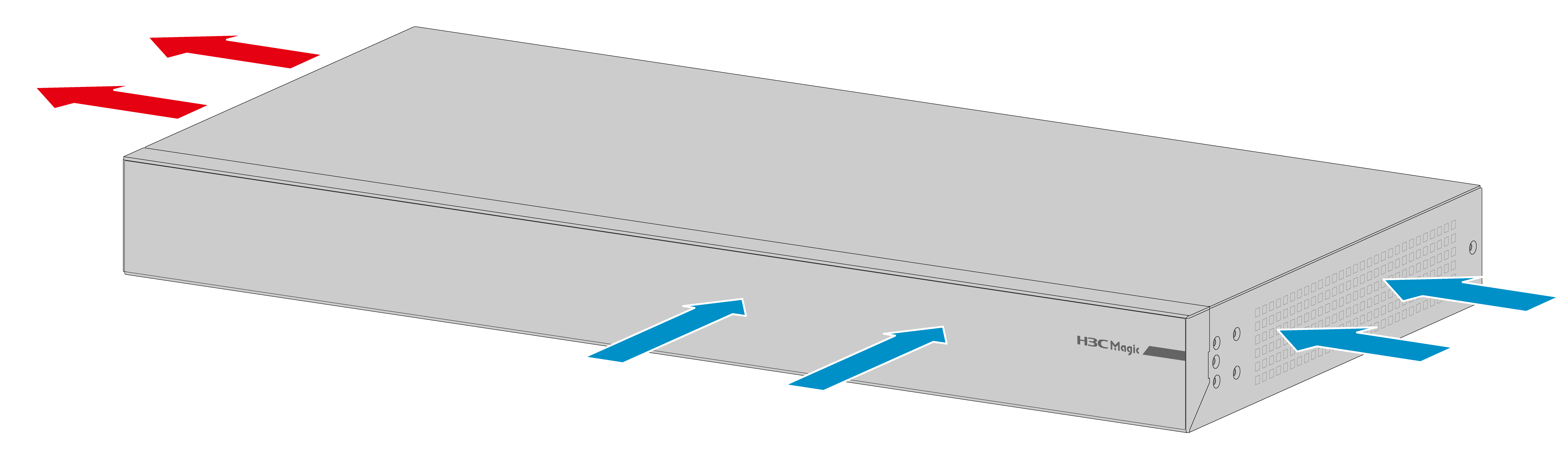
4 Cooling system
With an efficient cooling system, the switch ensures that the heat generated can be discharged in time to improve its stability. Install the switch by considering the ventilation conditions of the environment.
Some models of the switch series are provided with fixed fans:
· BS218F-HP: Cooling air flows in from the right side of the chassis and the port and flows out from the left side of the chassis (views of the user facing the side panel of the device port).
Figure4-1 Cooling air flow (BS218F-HP)