- Table of Contents
- Related Documents
-
| Title | Size | Download |
|---|---|---|
| 01-Text | 1.33 MB |
Preventing electrostatic discharge
Grounding methods to prevent electrostatic discharge
Overview of the BX608FE FC switch module
Internal connections between ICM and mezzanine network adapter
Internal connections between ICM and mezzanine network adapter port
Compatibility between switch modules and mezzanine network adapters
Compatibility between switch modules and optical modules/cables
Powering on and powering off the switch module
Powering off the switch module
Logging in to the switch module
Logging in to the switch module through the SYS serial port (console port)
Logging in to the SOL serial port through redirection
Configuring the management IP address of the switch module
Obtaining and planning related data
Configuring the management IP address from the OM Web interface
Configuring the management IP address through the CLI of the OM module
Configuring the management IP address through the CLI of the switch module
Configuring switch module services
Logging in to the OM Web interface
Safety
Safety information
To avoid personal injury or damage to the device, read the following information carefully before you operate the device. Safety precautions in actual operation include but are not limited to safety information mentioned in this document.
General operating safety
· Only H3C authorized or professional engineers are allowed to operate the device.
· Keep the device clean and dust-free. Do not place it in a humid place or allow liquids to enter it.
· Before powering on the device, ensure that the blade server chassis is securely grounded.
· To maintain sufficient heat dissipation, use filler panels on idle slots.
Electrical safety
· Carefully check any potential hazards in the work area, for example, whether the ground is wet and whether the blade server chassis is grounded or reliably grounded.
· Do not work alone when performing live-line maintenance.
· Do not touch the power supply directly or indirectly through conductive objects to prevent electric shock.
Safety precautions
· When maintaining the device, place the device on a clean, stable table or floor.
· To avoid personal injury from hot surfaces or internal components, allow the device and its internal components to cool before touching them.
· When using tools to maintain the device, follow the correct operation methods to avoid damage to the personnel or device.
· When connecting, testing or replacing optical fibers, do not look directly into the optical fiber outlet to prevent the laser beam from hurting your eyes.
· Gently and slowly transport or place the device with force evenly distributed.
ESD prevention
Preventing electrostatic discharge
Electrostatic charges that build up on people and conductors damage or shorten the lifespan of the main board and electrostatic-sensitive components.
To prevent electrostatic damage, follow these guidelines:
· Transport or store the device in an ESD bag.
· Place the device on a grounded table before taking it out of the ESD bag.
· Avoid touching pins or circuitry of the device without taking any ESD prevention measures.
Grounding methods to prevent electrostatic discharge
When removing or installing the device, you can use one or multiple of the following grounding methods to prevent electrostatic discharge:
· Wear an ESD wrist strap and ensure that it is reliably grounded. Ensure that the ESD wrist strap makes good skin contact and can be flexibly stretched out and draw back.
· In the work areas, wear the ESD clothing and shoes.
· Use conductive field service tools.
· Use a portable field service kit with a folding ESD tool mat.
Overview of the BX608FE FC switch module
Product overview
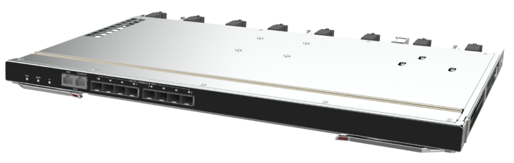
As an FC switching control unit inside the blade server chassis, the H3C UniServer BX608FE switch module provides data switching functions for servers installed in the blade server chassis and centrally provides external data ports, to achieve the communication between blade servers and external networks.
Figure 1 shows the appearance of the BX608FE FC.
Specifications
Table 1 describes the specifications of the switch module.
|
Category |
Item |
Description |
|
Physical specifications |
Dimensions (H × W × D) |
27 × 491.6 × 296.5 mm (1.06 × 19.35 × 11.67 in) |
|
Maximum weight |
3.80 kg (8.38 lb) |
|
|
Power consumption |
Maximum power consumption |
95 W |
|
Environment specifications |
Temperature |
· Operating temperature: 5°C to 45°C (41°F to 113°F) · Storage temperature: –40°C to +70°C (–40°F to +158°F) |
|
· Operating humidity: 8% to 90% (non-condensing) · Storage humidity: 5% to 95% (non-condensing) |
||
|
· Operating altitude: –60 m to +5000 m (–196.85 ft to +16404.20 ft) (The allowed maximum temperature decreases by 0.33 °C (32.59°F) as the altitude increases by 100 m (328.08 ft) from 900 m (2952.76 ft)) · Storage altitude: –60 m to +5000 m (–196.85 ft to +16404.20 ft) |
Port
This section describes numbering rules, positions, quantity, and other information about the ports of the switch module.
Port numbering rules
Ports of the switch module are numbered in three dimensions: A, B, and C.
· A: Indicates the number of the IRF member device. Since the switch module does not have any IRF by default, the default value of A is 1. Devices with the same IRF member ID cannot form an IRF fabric. To change the member ID of a device, use the irf member renumber command.
· B: Indicates an internal or external port. 0 indicates an internal port, and 1 indicates an external port.
· C: Indicates the sequence number of the port.
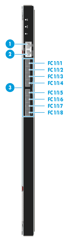
External ports
Figure 2 shows the external ports provided by the switch module. Table 2 describes specific functions of the external ports.
|
(1) AMC serial port |
(2) SYS serial port (Console port) |
|
(3) 16GE FC optical port |
|
Table 2 Description of external ports
|
SN |
Port Name |
Port Type |
Port Quantity |
Description |
|
1 |
AMC serial port |
RJ-45 |
1 |
Serial port used to enter the AMC CLI of the switch module. The baud rate is 115200 bit/s. It is only used by technical support engineers to upgrade the AMC firmware. |
|
2 |
SYS serial port (Console port) |
RJ-45 |
1 |
Serial port used for local management, debugging, and maintenance of the switch module. The baud rate is 9600 bit/s. You can log in to the CLI of the switch module through the SYS serial port. |
|
3 |
16GE FC optical port |
FC16 |
8 |
N/A |
|
For details about the optical modules and cables supported by the switch module as well as their specifications, see "Compatibility between switch modules and optical modules/cables." |
||||
Internal ports
Table 3 shows the internal port provided by the switch module.
Table 3 Description of the internal port
|
Port type |
Port quantity |
Description |
|
|
FC port |
FC16 |
16 |
A total of 16 ports are provided to connect to blade servers. |
|
10GE port |
N/A |
4 |
Used to connect to switch modules installed in pairs in slots 1 and 4, 2 and 5, and 3 and 6. The ports are numbered XGE1/0/17 through XGE1/0/20. The four ports are connected to each other through the mid plane. As a best practice, use the ports as physical ports for IRF connection. |
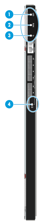
LEDs
Figure 3 shows positions and appearance of LEDs on the switch module. Table 4 describes LED colors and the corresponding meaning.
|
(1) UID LED |
(2) RUN LED |
|
(3) Health LED |
(4) Port LED |
|
The appearance of all port LEDs of the switch module is identical. The figure takes one port LED for illustration. |
|
|
No. |
Name |
Color |
Status |
|
1 |
UID LED |
Blue |
· Steady blue: The UID LED is activated (through the OM module). · Flashing blue (1 Hz): The switch module is under remote management through SOL or the firmware is being updated through the OM module. · Off: The UID LED is not activated. |
|
2 |
RUN LED (RUN) |
Green |
· Steady green/off: The system is faulty. · Flashing green (4 Hz): The system is loading data. · Flashing green (1 Hz): The system is running correctly. |
|
3 |
Health LED ( |
Red/Green |
· Steady green: The switch module is running correctly. · Flashing red (1 Hz): The switch module generates an alarm. · Off: The switch module is not powered on or in position. |
|
4 |
Port LED |
Yellow/Green |
16G FC port · Steady green: The port link is connected, the port rate is 16 Gbit/s, but no data is transmitted. · Flashing green: The port link is connected, the port rate is 16 Gbit/s, and data transmission is in progress. · Steady yellow: The port link is connected, the port rate is 8 Gbit/s, but no data is transmitted. · Flashing yellow: The port link is connected, the port rate is 8 Gbit/s, and data transmission is in progress. · Off: The port link is not connected. |
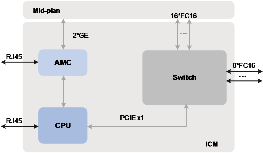
Logical structure
Figure 4 shows major units in the logical structure of the switch module.
· CPU unit: As the control and management core of the switch module, the CPU unit is mainly responsible for device management, system configuration, and special packet processing.
· AMC unit: As the auxiliary management unit of the switch module, the AMC unit is mainly responsible for ICM data collection and reporting, ICM power-on/off control, and system monitoring.
· Switch unit: As the data processing core of the switch module, the switch unit is mainly responsible for internal and external data forwarding and unrecognizable packet reporting.
Installation guidelines
· As shown in Figure 5, up to six switch modules can be installed in the blade server chassis.
· The installation positions of the switch modules and mezzanine network adapters must satisfy internal connection relationships. For details, see Figure 6 and Figure 7.
· Six switch module slots can be divided into three pairs, corresponding to three switching planes. Where, slots 1 and 4, slots 2 and 5, and slots 3 and 6 function as the active and standby slots of three switching planes.
· The switch module is hot swappable.
Figure 5 Guidelines for installing the switch module

|
(1) ICM1 slot |
(2) ICM2 slot |
(3) ICM3 slot |
|
(4) ICM4 slot |
(5) ICM5 slot |
(6) ICM6 slot |
Internal networking
Internal connections between ICM and mezzanine network adapter
Table 5 describes the internal connections between ICMs and mezzanine network adapters on blade servers. Make sure the ICMs and mezzanine network adapters are installed in the correct slots so that the internal connection requirements can be met.
Table 5 Connections between ICM and mezzanine network adapter
|
Model of blade server |
Maximum number of supported mezzanine network adapters |
Internal connections |
|
|
H3C UniServer B5700 G5 |
3 |
The connection diagram is a logical diagram used to identify the mapping between mezzanine network adapter slot and switch module slot. The specific positions of the mezzanine network adapter slots and switch module slots should be subject to the module silkscreens. |
|
|
H3C UniServer B5700 G3 |
3 |
||
|
H3C UniServer B7800 G3 |
6 |
||
|
H3C UniServer B5800 G3 |
3 |
||
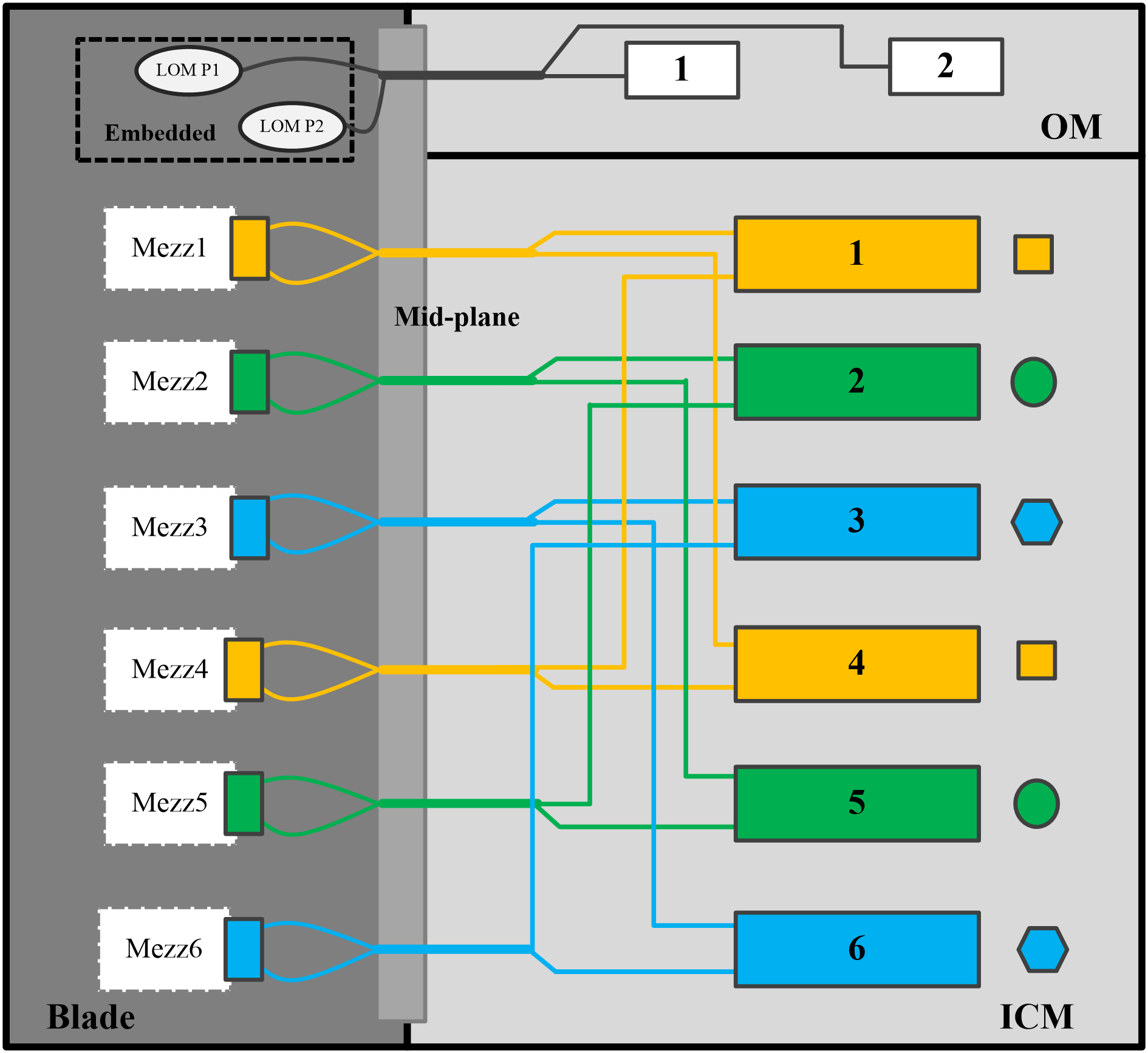
Figure 6 shows the first mode of connections between switch modules and mezzanine network adapters, where:
· The onboard network adapter is connected to the active and standby OM modules.
· Mezzanine network adapter 1 is connected to switch modules in slot 1 and slot 4.
· Mezzanine network adapter 2 is connected to switch modules in slot 2 and slot 5.
· Mezzanine network adapter 3 is connected to switch modules in slot 3 and slot 6.
Figure 6 Connections between switch modules and mezzanine network adapters (1)

Figure 7 shows the second mode of connections between switch modules and mezzanine network adapters, where:
· The onboard network adapter is connected to the active and standby OM modules.
· Mezzanine network adapter 1 and mezzanine network adapter 4 are connected to switch modules in slot 1 and slot 4.
· Mezzanine network adapter 2 and mezzanine network adapter 5 are connected to switch modules in slot 2 and slot 5.
· Mezzanine network adapter 3 and mezzanine network adapter 6 are connected to switch modules in slot 3 and slot 6.
Figure 7 Connections between switch modules and mezzanine network adapters (2)
Internal connections between ICM and mezzanine network adapter port
You must identify the connection relations between ICM and mezzanine network adapter port when configuring a mezzanine network adapter. For more information, contact Technical Support.
Hardware compatibility
This section describes the compatibility between switch modules and mezzanine network adapters and the compatibility between switch modules and optical modules/cables.
Compatibility between switch modules and mezzanine network adapters
Table 6 describes the compatibility between the BX608FE FC switch module and the mezzanine network adapter.
Table 6 Mezzanine network adapters compatible with the switch module
|
Mezz network adapter model |
Port quantity |
Description |
|
NIC-FC680i-Mb-2*16G |
2 |
2-Port 16Gb FC mezzanine network adapter |
|
NIC-FC730i-Mb-2P |
2 |
2-Port 32Gb FC mezzanine network adapter |
Compatibility between switch modules and optical modules/cables
Table 7 describes the compatibility between the BX608FE FC switch module and the optical modules/cables.
Table 7 Optical modules/cables compatible with the switch module
|
Model |
Type |
Center wavelength |
Transmission distance |
Description |
|
QSFP-40G-D-AOC-20M |
QSFP+ |
N/A |
20 m (65.62 ft) |
QSFP+ active cable |
|
QSFP-40G-D-AOC-20M |
QSFP+ |
N/A |
20 m (65.62 ft) |
QSFP+ active cable |
|
SFP-FC-8G-SW-MM850-CM |
SFP |
850 nm |
· 150 m (492.13ft) (8G) · 380 m (1246.72 ft) (4G) · 500 m (1640.42 ft) (2G) |
8G/4G/2G FC optical module |
|
SFP-FC-8G-SW-MM850 |
SFP |
850 nm |
· 150 m (492.13ft) (8G) · 380 m (1246.72 ft) (4G) · 500 m (1640.42 ft) (2G) |
8G/4G/2G FC optical module |
|
SFP-FC-16G-SW-MM850-CM |
SFP |
850 nm |
· 100 m (328.08 ft) (16G) · 150 m (492.13 ft) (8G) · 380 m (1246.72 ft) (4G) |
16G/8G/4G FC optical module |
|
SFP-FC-16G-SW-MM850 |
SFP |
850 nm |
· 100 m (328.08 ft) (16G) · 150 m (492.13 ft) (8G) · 380 m (1246.72 ft) (4G) |
16G/8G/4G FC optical module |
|
SFP-FC-16G-LW-SM1310-CM |
SFP |
1310 nm |
10 km (6.21 miles) |
16G/8G/4G FC optical module |
|
SFP-FC-16G-LW-SM1310 |
SFP |
1310 nm |
10 km (6.21 miles) |
16G/8G/4G FC optical module |
|
|
NOTE: · H3C SFP/SFP+ modules are recommended as switch modules. · For specifications of optical modules or cables, see the H3C Optical Module Manual. · The types of H3C SFP/SFP+ modules may change over time. If you need accurate information about module types, consult H3C marketing or technical support personnel. · When installing optical modules and cables, wear ESD wrist straps. For installation methods and precautions, see the H3C Optical Module and Cable Installation Guide. |
Replacing the switch module
Scenario
· The switch module is faulty.
· The switch module needs to be replaced by a switch module or straight-through module in another model.
Installation tools
The following tools or devices may be required when you install, use, and maintain the equipment.
|
Image |
Name |
Description |
|
|
Diagonal pliers |
Used to clip insulating sleeves and binding straps |
|
|
Multimeter |
Used to measure resistance and voltage and check the circuitry |
|
|
ESD wrist strap |
Used for installing, removing, or maintaining the equipment |
|
|
ESD gloves |
|
|
|
ESD clothing |
|
|
|
Ladder |
Used for work at heights |
|
|
Interface cable (such as an Ethernet cable or optical fiber) |
Used to connect the equipment with the external network |
|
|
Login device (such as a PC) |
Used to log in to the equipment |


Preparations
· Take ESD preventive measures: Wear the ESD clothing. Properly wear and ground the ESD wrist strap. Remove conductive objects (such as jewelry or watch).
· Back up data of the switch module.
· Before replacing a component, check the slots and connectors, and ensure that the pins are not damaged (for example, check whether pins are deformed or whether foreign objects are on the connectors).
· Understand the guidelines for installing the switch module, as described in "Installation guidelines."
Replacement procedure
Remove the switch module. Press the unlock button on the switch module to fully open the ejector, and slowly pull the switch module out of the chassis horizontally.
Put the switch module into the ESD bag.
Install the switch module. Take out the switch module to be installed from the ESD bag.
Press the unlock button to automatically open the ejector.
Slowly insert the switch module into the blade server chassis horizontally with UP facing upwards, and then lock the ejector.
Powering on and powering off the switch module
This section describes how to power on/off the switch module.
Powering on the switch module
This section describes how to power on the switch module.
Supported power-on methods
Table 9 describes power-on methods supported by the switch module.
Table 9 Power-on methods supported by the switch module
|
Power-on mode |
Application scenario |
|
Method 1: Power on the switch module together with the blade server chassis |
· The switch module is installed before the blade server chassis is powered on. · The switch module is installed after the blade server chassis is powered on. |
|
Method 2: Power on the switch module from the OM Web interface |
The blade server chassis is powered on. The switch module is installed but is not energized. The Health LED of the switch module is off. |
|
Method 3: Power on the switch module from the OM CLI |
Operation methods
After the switch module is successfully powered on, the Health LED is steady green. For specific positions of LEDs, see "LEDs."
Method 1: Power on the switch module together with the blade server chassis
If the switch module is installed before the chassis is powered on, it is automatically powered on along with the blade server chassis. If the switch module is installed after the chassis is powered on, it is automatically powered on once installed.
No manual intervention is required.
Method 2: Power on the switch module from the OM Web interface
1. Obtain OM login information.
Table 10 OM login information
|
Data |
Description |
|
OM management IP address |
· Management IP address (default): 192.168.100.100 · Subnet mask (default): 255.255.255.0 |
|
Username and password used for OM login |
· Username (default): admin · Password (default): Password@_ |
|
Switch module slot |
Slot number: 1 |
|
· The default settings refer to settings in the factory defaults. · The data in the table is for illustration only. The actual data during on-site operations shall prevail. |
|
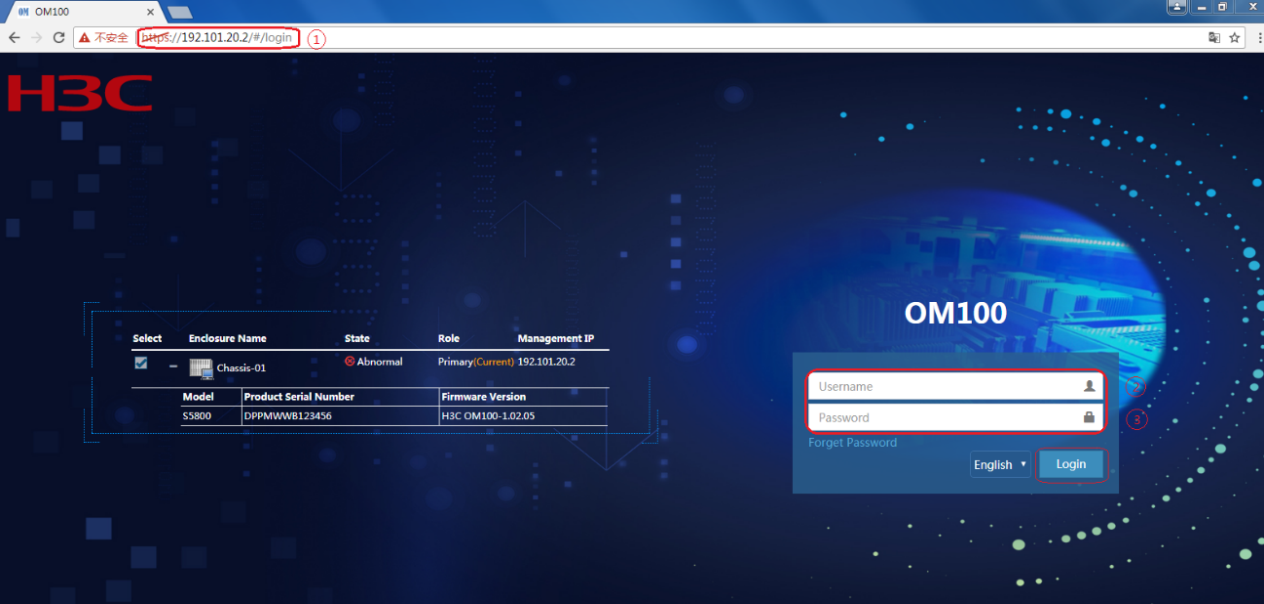
2. Open the browser on the PC and enter the OM login address in the format of https://OM_ip_address. Enter the admin username and password, and then click Login.
Figure 8 Logging in to the OM Web interface

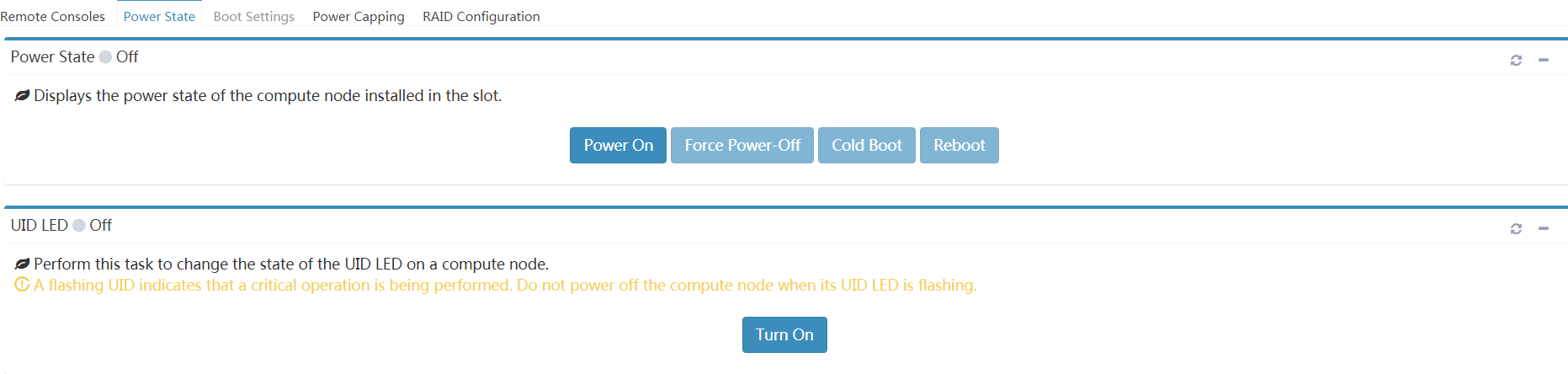
3. Perform the following tasks to power on the switch module:
a. Click Interconnect Module Management.
b. Select the target switch module.
c. Click Power State, and click Power On.
d. Click OK.
Figure 9 Powering on the switch module

4. Verify that the switch module is powered on.
Figure 10 Verifying the switch module power state

Method 3: Power on the switch module from the OM CLI
1. Set the SSH login parameters and log in to the OM CLI by using the remote access software.
|
Login parameters |
Data |
|
Protocol |
SSH |
|
Port number |
22 |
|
· Management IP address (default): 192.168.100.100 · Subnet mask (default): 255.255.255.0 |
|
|
Username and password used for OM login |
· Username (default): admin · Password (default): Password@_ |
|
· SSH access is enabled for the OM module by default. · The default settings refer to settings in the factory defaults. · The data in the table is for illustration only. The actual data during on-site operations shall prevail. |
|
After login, the OM CLI displays the login page.
******************************************************************************
* Copyright (c) 2004-2020 New H3C Technologies Co., Ltd. All rights reserved.*
* Without the owner's prior written consent, *
* no decompiling or reverse-engineering shall be allowed. *
******************************************************************************
<OM>
2. Use io on CPU 1 to power on the switch module in slot 1.
<OM> io 1 CPU on
3. Use display io list to check whether the switch module in slot 1 is powered on.
<OM>display io list
Slot : 1
Running status : Normal
UID LED : Off
PSU : On
Management URL : http://192.168.200.1/web/index.html
Product name : BX608FE
CPU usage : 15%
Powering off the switch module
This section describes how to power off the switch module.
Supported power-off methods
Table 12 describes power-off methods supported by the switch module.
Table 12 Power-off methods supported by the switch module
|
Power-off method |
Application scenario |
|
Method 1: Power off the switch module together with the blade server chassis. |
N/A |
|
Method 2: Power off the switch module from the OM Web interface. |
The blade server chassis and switch module are powered on, the switch module works correctly. |
|
Method 3: Power off the switch module from the OM CLI. |
Operation methods
After the switch module is successfully powered off, the Health LED is off. For specific positions of LEDs, see "LEDs."
Method 1: Power off the switch module together with the blade server chassis
The switch module is automatically powered off as the blade server chassis is powered off. No manual intervention is required.
Method 2: Power off the switch module from the OM Web interface
1. Obtain the OM login information.
Table 13 OM login information
|
Data |
Description |
|
OM management IP address |
· Management IP address (default): 192.168.100.100 · Subnet mask (default): 255.255.255.0 |
|
Username and password used for OM login |
· Username (default): admin · Password (default): Password@_ |
|
Switch module slot |
Slot number: 1 |
|
· The default settings refer to settings in the factory defaults. · The data in the table is for illustration only. The actual data during on-site operations shall prevail. |
|
2. Open the browser on the PC and enter the OM login address in the format of https://OM_ip_address. Enter the admin username and password, and then click Login.
Figure 11 Logging in to the OM Web interface
3. Power off the switch module:
a. Click Interconnect Module Management.
b. Select the target switch module.
c. Click Power state, and then click Power Off.
d. Click OK.
Figure 12 Powering off the switch module

4. Verify that the switch module is powered off.
Figure 13 Verifying the power state of the switch module
Method 3: Power off the switch module from the OM CLI
1. Set the SSH login parameters and log in to the OM CLI by using the remote access software.
Table 14 SSH login parameters
|
Login parameters |
Data |
|
Protocol |
SSH |
|
Port number |
22 |
|
OM management IP address |
· Management IP address (default): 192.168.100.100 · Subnet mask (default): 255.255.255.0 |
|
Username and password used for OM login |
· Username (default): admin · Password (default): Password@_ |
|
· SSH access is enabled for the OM module by default. · The default settings refer to settings in the factory defaults. · The data in the table is for illustration only. The actual data during on-site operations shall prevail. |
|
After login, the OM CLI displays the login page.
******************************************************************************
* Copyright (c) 2004-2020 New H3C Technologies Co., Ltd. All rights reserved.*
* Without the owner's prior written consent, *
* no decompiling or reverse-engineering shall be allowed. *
******************************************************************************
<OM>
2. Use io 1 CPU off to power off the switch module in slot 1.
<OM> io 1 CPU off
3. Use display io list to check whether the switch module in slot 1 is powered off.
<OM>display io list
Slot : 1
Running status : Normal
UID LED : Off
PSU : Off
Management URL :
Product name : BX608FE
CPU usage : 0%
Configuring the switch module
|
|
NOTE: The data in operations of this section is used for illustration only. The actual operation data on site shall prevail. |
Logging in to the switch module
Obtaining the related data
Before logging in to the switch module, obtain the related data, as described in Table 15.
|
Required data |
Example |
|
OM management IP address |
· Management IP address (default): 192.168.100.100 · Subnet mask (default): 255.255.255.0 |
|
Username and password used for OM login |
· Username (default): admin · Password (default): Password@_ |
|
Switch module slot |
· Slot number: 1 |
|
· The default settings refer to settings in the factory defaults. · The data in the table is for illustration only. The actual data during on-site operations shall prevail. |
|
Login methods
You can log in to the switch module in either of the following methods:
· Log in to the switch module through the SYS serial port (Console port) on the switch module. For more information, see "Logging in to the switch module through the SYS serial port (console port)."
· Log in to the switch module from the OM CLI through SOL serial port redirection. For more information, see "Logging in to the SOL serial port through redirection."
Logging in to the switch module through the SYS serial port (console port)
Prerequisites
· The switch module has been powered on. For more information, see "Powering on the switch module."
· The PC has been connected to the SYS serial port (Console port) of the switch module. For more information about the position of the SYS serial port (console port), see "External ports."
Procedure
1. Set the login parameters and log in to the CLI of the switch module through the console port by using the remote login software.
|
Data |
|
|
Serial Line to connect to |
COMn, where n indicates the serial port number. The value is an integer. The specific value is subject to the actual settings. |
|
Speed (baud) |
9600 (default) |
|
Data bits |
8 (default) |
|
Stop bits |
1 (default) |
|
Parity |
None (default) |
|
Flow control |
None (default) |
|
The default settings refer to settings in the factory defaults. |
|
After login, the CLI of the switch module displays the login page.
********************************************************************************
* Copyright (c) 2004-2019 New H3C Technologies Co., Ltd. All rights reserved. *
* Without the owner's prior written consent, *
* no decompiling or reverse-engineering shall be allowed. *
********************************************************************************
<Sysname>
Logging in to the SOL serial port through redirection
Prerequisites
· The switch module has been powered on. For more information, see "Powering on the switch module."
· You have logged in to the CLI of the OM module. For more information, see "Logging in to the CLI of the OM module."
Procedure
Use the sol connect command from the OM CLI to log in to the CLI of the switch module in slot 1.
<OM>sol connect io 1
Begin to edit commands.
<Sysname>%Jul 29 13:42:35:975 2013 H3C SHELL/5/SHELL_LOGIN: Console logged in from c
on1.
<Sysname>
|
|
NOTE: After logging in to the CLI of the switch module through the SOL serial port in the redirection method, enter "~" and "." in sequence (the entered "~" is not displayed on the CLI) in any view. Press Enter to log out and go back to the OM CLI. |
Configuring the management IP address of the switch module
Obtaining and planning related data
Before configuring the management IP address of the switch module, obtain and plan the related data, as described in Table 17.
|
Data |
Example |
|
Required Data |
|
|
OM management IP address |
· Management IP address (default): 192.168.100.100 · Subnet mask (default): 255.255.255.0 |
|
Username and password used for OM login |
· Username (default): admin · Password (default): Password@_ |
|
Switch module slot |
· Slot number: 1 |
|
Planned data |
|
|
Data planned for the switch module |
· IP address: 192.168.200.1 · Subnet mask: 255.255.255.0 · Gateway: 192.168.200.254 |
|
· The default settings refer to settings in the factory defaults. · The data in the table is for illustration only. The actual data during on-site operations shall prevail. |
|
Configuration methods
You can configure the management IP address of the switch module in one of the following methods:
· Configure the management IP address of the switch module through the OM Web interface. For more information, see "Configuring the management IP address from the OM Web interface."
· Configure the management IP address of the switch module through the CLI of the OM module. For more information, see "Configuring the management IP address through the CLI of the OM module."
· Configure the management IP address of the switch module through the CLI of the switch module. For more information, see "Configuring the management IP address through the CLI of the switch module."
Configuring the management IP address from the OM Web interface
Prerequisites
· The switch module has been powered on. For more information, see "Powering on the switch module."
· For more information about how to log in to the OM Web interface, see "Logging in to the OM Web interface."
Procedure
1. Select Enclosure > Enclosure > Network > IPv4 Setting.
Figure 14 Configure the management IP address (1)

2. Toggle on the Enable in Position button to enable the function of configuring the management IPv4 address of the ICM module, and configure the management IP address of the ICM module. Click Apply.
Figure 15 Configure the management IP address (2)
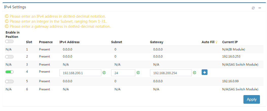
3. In the window that appears, click OK.
Figure 16 Configure the management IP address (3)

|
|
NOTE: (Optional.) In the window that appears, enable Save Configuration File. Select the slot in which the switch module resides. Then, the system can save the current configuration information of the switch module in the selected slot. |
Configuring the management IP address through the CLI of the OM module
Prerequisites
· The switch module has been powered on. For more information, see "Powering on the switch module."
· You have logged in to the CLI of the OM module. For more information, see "Logging in to the CLI of the OM module."
Procedure
From the OM CLI, use the auto-ipv4 command to configure the management IP address of the switch module in slot 1. When configuring the management IP address of the switch module, you can determine whether to save the configuration in the profile. The configuration methods include:
· Configure the management IP address and save the configuration in the profile:
<OM>auto-ipv4 address 192.168.200.1 mask 255.255.255.0 gateway 192.168.200.254 io 1 save enable
· Configure the management IP address but do not save the configuration in the profile:
<OM>auto-ipv4 address 192.168.200.1 mask 255.255.255.0 gateway 192.168.200.254 io 1 save disable
Configuring the management IP address through the CLI of the switch module
Prerequisites
· The switch module has been powered on. For more information, see "Powering on the switch module."
· You have logged in to the switch module. For more information, see "Logging in to the switch module."
Procedure
For the procedures, see the configuration guides and command references for the H3C UniServer BX608FE switch module.
Configuring switch module services
Prerequisites
· The switch module has been powered on. For more information, see "Powering on the switch module."
· You have logged in to the switch module. For more information, see "Logging in to the switch module."
· You have planned functions required by services of the switch module according to actual requirements.
Procedure
For the procedures, see the configuration guides and command references for the H3C UniServer BX608FE switch module.
Saving the configuration file
Prerequisites
· The switch module has been powered on. For more information, see "Powering on the switch module."
· You have logged in to the switch module. For more information, see "Logging in to the switch module."
Procedure
1. In the user view on the CLI of the switch module, use the dir command to view the current file system of the switch module. Check the boot file name, profile name, and available space of the Flash memory, and ensure that the flash memory has sufficient space to save new boot file.
<Sysname> dir
Directory of flash:
0 drw- - Apr 17 2019 17:43:29 diagfile
1 drw- - Apr 08 2019 14:49:27 flyfishlog
2 -rw- 412 Apr 29 2019 10:50:54 ifindex.dat
3 drw- - Apr 17 2019 17:43:29 logfile
4 drw- - Apr 08 2019 14:51:51 pki
5 drw- - Apr 08 2019 14:49:17 seclog
6 -rw- 2649 Apr 29 2019 10:50:54 startup.cfg
7 -rw- 669171 Apr 29 2019 10:50:55 startup.mdb
8 -rw- 5705728 Apr 28 2019 14:35:55 uis-cmw710-boot-1.00.10.bin
9 -rw- 108381184 Apr 28 2019 14:36:52 uis-cmw710-system-1.00.10.bin
10 -rw- 7168 Apr 29 2019 14:06:09 uis.db
11 -rw- 7168 Apr 29 2019 14:06:09 uis_bak.db
12 drw- - Apr 22 2019 11:19:19 versionInfo
<Sysname>
2. In any view on the CLI of the switch module, use the save command to save the current configuration information of the switch module.
<Sysname> save
The current configuration will be written to the device. Are you sure? [Y/N]:y
Please input the file name(*.cfg)[flash:/startup.cfg]
(To leave the existing filename unchanged, press the enter key):
flash:/startup.cfg exists, overwrite? [Y/N]:y
Validating file. Please wait...
Saved the current configuration to mainboard device successfully.
<Sysname>
3. In the user view on the CLI of the switch module, run the tftp put command to back up the system file and boot file on the TFTP file server.
<Sysname>tftp 192.168.1.1 put flash:/uis-cmw710-system-1.00.10.bin
Press CTRL+C to abort.
% Total % Received % Xferd Average Speed Time Time Time Current
Dload Upload Total Spent Left Speed
84 103M 0 0 84 87.0M 0 851k 0:02:04 0:01:44 0:00:20 837k
<Sysname>tftp 192.168.1.1 put flash:/uis-cmw710-boot-1.00.10.bin
Press CTRL+C to abort.
% Total % Received % Xferd Average Speed Time Time Time Current
Dload Upload Total Spent Left Speed
100 5572k 0 0 100 5572k 0 832k 0:00:06 0:00:06 --:--:-- 828k
<Sysname>
4. In the user view on the CLI of the switch module, use the tftp put command to back up profile startup.cfg on the TFTP file server:
<Sysname>tftp 192.168.1.1 put startup.cfg
Press CTRL+C to abort.
% Total % Received % Xferd Average Speed Time Time Time Current
Dload Upload Total Spent Left Speed
100 6549 0 0 100 6549 0 270k --:--:-- --:--:-- --:--:-- 319k
<Sysname>
Interconnection suggestions
Interconnection suggestions
Table 18 describes suggestions for configuring the interconnection between the FC switch module and the FC switch of another vendor in FCoE mode.
Table 18 Interconnection configuration suggestions
|
Peer device |
Local device |
Configuration suggestions |
|
FC core switch of another vendor |
Core switch |
It is recommended that the FCoE mode of the FC switch module be set to FCF mode. For specific configuration methods, see "Setting the FCoE mode to FCF." |
|
FC non-core switch of another vendor |
Non-core switch |
It is recommended that the FCoE mode of the FC switch module be set to NPV mode. For specific configuration methods, see "Setting the FCoE mode to NPV." |
Setting the FCoE mode to FCF
Prerequisites
· You have configured the mezzanine network adapter. For more information, see the mezzanine network adapter user guide.
· You have logged in to the switch module. For more information, see "Logging in to the switch module."
Procedure
|
|
NOTE: Before setting the FCoE mode to FCF, check whether the switch module works in another FCoE mode. If yes, disable the corresponding FCoE mode. Run the following command in the system view: [BX608FE]undo fcoe-mode All current FC configuration will be lost. Continue? [Y/N]:y |
1. Access the system view.
<BX608FE>system-view
2. In the system view, set the FCoE mode of the BX608FE FC switch module to FCF.
[BX608FE]fcoe-mode fcf
3. Configure the interface mode.
Configure the interface mode of the BX608FE FC switch module based on the type and interface mode of the peer device on the actual network, as shown in Table 19. For details about the configuration commands and procedures, see the configuration guides and command references for the BX608FE FC switch module.
Table 19 Configuring the interface mode in FCF mode
|
Peer device and interface mode |
Local interface mode |
|
E_Port of another switch |
E_Port |
|
· NP_Port of another switch · N_Port of the node device |
F_Port |
|
Note: When the BX608FE FC switch module works in FCF mode, the interface supports Auto, E, and F modes, and the Auto mode is selected by default. The interfaces working in E and F modes are known as E_Port and F_Port respectively. |
|
Setting the FCoE mode to NPV
Prerequisites
· You have configured the mezzanine network adapter. For more information, see the mezzanine network adapter user guide.
· You have logged in to the switch module. For details, see "Logging in to the switch module."
Procedure
|
|
NOTE: Before setting the FCoE mode to NPV, check whether the switch module works in another FCoE mode. If yes, disable the corresponding FCoE mode. Run the following command in the system view: [BX608FE]undo fcoe-mode All current FC configuration will be lost. Continue? [Y/N]:y |
1. Access the system view.
<BX608FE>system-view
2. In the system view, set the FCoE mode of the BX608FE FC switch module to NPV.
[BX608FE]fcoe-mode npv
3. Configure the interface mode.
Configure the interface mode of the BX608FE FC switch module based on the type and interface mode of the peer device on the actual network, as shown in Table 20. For details about the configuration commands and procedures, see the configuration guides and command references for the BX608FE FC switch module.
Table 20 Configuring the interface mode in NPV mode
|
Peer device and interface mode |
Local interface mode |
|
· NP_Port of another switch · N_Port of the node device |
F_Port |
|
F_Port of another switch |
NP_Port |
|
When the BX608FE FC switch module works in NPV mode, the interface supports F and NP modes, which are known as F_Port and NP_Port. By default, the F mode is selected. |
|
Common operations
Logging in to the OM Web interface
Prerequisites
· The blade server chassis has been powered on.
· You have obtained the login data of the OM module.
Procedure
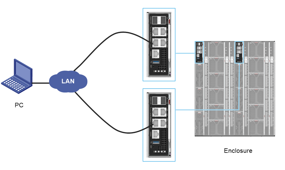
1. Connect the Ethernet interface of the PC to the MGMT interfaces of the active or standby OM module through a LAN. Make sure the PC and OM module can reach each other at Layer 3.
Figure 17 Setting up the hardware environment

2. Open the browser on the PC and enter the OM login address in the format of https://OM_ip_address. Enter the admin username and password, and then click Login.
Figure 18 Logging in to the OM Web interface

Logging in to the CLI of the OM module
Prerequisites
· The blade server chassis has been powered on.
· You have obtained the login data of the OM module.
Procedure
1. Connect the Ethernet interface of the PC to the MGMT interfaces of the active or standby OM module through a LAN. Make sure the PC and OM module can reach each other at Layer 3.
Figure 19 Setting up the hardware environment
2. Set the login parameters and log in to the OM CLI by using the remote access software.
|
Login parameter |
Data |
|
Protocol |
SSH |
|
Port number |
22 |
|
OM management IP address |
· Management IP address (default): 192.168.100.100 · Subnet mask (default): 255.255.255.0 |
|
Username and password used for OM login |
· Username (default): admin · Password (default): Password@_ |
|
· SSH access is enabled for the OM module by default. · The default settings refer to settings in the factory defaults. · The data in the table is for illustration only. The actual data during on-site operations shall prevail. |
|
After login, the OM CLI displays the login page.
******************************************************************************
* Copyright (c) 2004-2019 New H3C Technologies Co., Ltd. All rights reserved.*
* Without the owner's prior written consent, *
* no decompiling or reverse-engineering shall be allowed. *
******************************************************************************
<OM>
Firmware upgrade
For specific procedures, see H3C UniServer B16000 Blade Server Upgrade Guide.
