- Table of Contents
- Related Documents
-
| Title | Size | Download |
|---|---|---|
| 01-Text | 2.35 MB |
Preventing electrostatic discharge
Grounding methods to prevent electrostatic discharge
Powering on and powering off the OM module
Login through the console port
Login through the Web interface
Client configuration requirements
Logging in to the Web interface of the OM module
Logging in to the Web interface of the OM module
Setting basic information about the chassis
Setting basic information about the chassis
Setting the management IP address of the OM module
Setting the management IP address of chassis slot
Setting the working mode of the power supply
Changing the default user password
(Optional) Managing the cascaded chassis
Safety
Safety Information
To avoid personal injury or damage to the OM module, read the following information carefully before you operate the device. Safety precautions in actual operation include but are not limited to safety information mentioned in this document.
General Operating Safety
· Only H3C authorized or professional engineers are allowed to operate the OM module.
· Place the OM module on a clean, stable table or floor for servicing.
· Ensure that all cables are correctly connected before you power on the OM module.
· Keep the OM module clean and dust-free. Do not place it in a humid place or allow liquids to enter it.
· Gently and slowly transport or place the OM module with force evenly distributed.
· To avoid personal injury from hot surfaces, allow the OM module to cool before operation.
Electrical safety
· Carefully check any potential hazards in the work area, for example, whether the chassis is grounded or reliably grounded, and whether the ground is wet.
· Do not operate the OM module alone when the module is powered on.
Safety precautions
The safety precautions are as follows:
· To maintain sufficient heat dissipation, use filler panels on idle slots of the OM modules.
· When using tools, follow the correct operation methods to avoid damage to the OM module.
ESD prevention
Preventing electrostatic discharge
Electrostatic charges that build up on people and conductors damage or shorten the lifespan of the OM module.
To prevent electrostatic damage, follow these guidelines:
· Transport or store the OM modules in ESD bags.
· Keep the electrostatic-sensitive components in the ESD bags until they arrive at an ESD-protected area.
· Place the OM modules on a grounded table before taking them out of their ESD bags.
· Avoid touching pins, cables, or circuitry of the OM modules without taking any ESD prevention measures.
· Ensure that you take proper ESD measures when touching an electrostatic-sensitive component or assembly.
Grounding methods to prevent electrostatic discharge
When removing or installing components, you can use one or multiple of the following grounding methods to prevent electrostatic discharge:
· Wear an ESD wrist strap and ensure that it is reliably grounded. Ensure that the ESD wrist strap makes good skin contact and can be flexibly stretched out and draw back.
· In the work areas, wear the ESD clothing and shoes.
· Use conductive field service tools.
· Use a portable field service kit with a folding ESD work mat.
OM module overview
Overview
As a core management unit, the OM module interconnects with other modules inside the chassis through the mid-plane to manage and monitor all modules in a centralized manner. The OM module supports multiple protocols, including: SNMPv1, SNMPv2c, SNMPv3, SSL, SSH, SFTP, HTTPS, NTP, DNS, LDAP, and SMTP. In addition, the OM module integrates the GE switching function, which allows you to use the OM module as an extended service plane, thereby flexibly adapting to diversified external networks.
At least one OM module must be configured for a chassis. When two OM modules are configured, they work in active/standby mode. A single OM module is hot swappable.
Figure 1 shows the appearance of the OM module.

Function
Management
· Monitor the running status of each module in the chassis and implements intelligent power consumption management and speed regulation in an integrated manner.
· Collect alarms generated by modules inside the chassis and report the alarms to the upper-layer NMS.
· Provide functions such as remote startup and shutdown and power-on/off management for blade servers, ICM modules, and AE modules.
· Support log recording and query.
· Manage users, including local users and LDAP users.
· Manage multi-chassis cascading.
Remote control
By leveraging the remote control function of the OM module, you can log in to the blade server system or HDM to operate the system, manage the hardware, and mount images.
SOL
With the SOL function, the OM module can establish a serial data transmission channel to communicate with the blade server or ICM module, so as to remotely operate the serial port of the blade server or ICM module.
Unified upgrade
The OM module can uniformly upgrade the firmware of itself, ICM module, blade server, and AE module.
Power limit
The power limits of the chassis and blade server can be configured based on actual requirements.
Integrated service plane
The OM module integrates the GE switching function, which allows you to use the OM module as an extended service plane. The front panel provides four service ports used to connect the chassis to the external service network.
Specifications
Table 1 describes the OM module specifications.
|
Category |
Item |
Description |
|
Physical specifications |
Dimensions (W × H × D) |
115.5 × 40.5 × 295.8 mm (4.55 × 1.59 × 11.65 in) |
|
Maximum weight |
0.96 kg (2.12 lb) |
|
|
Power consumption |
Maximum power consumption |
30 W |
|
Environment specifications |
Temperature |
· Operating temperature: 5°C to 45°C (41°F to 113°F) · Storage temperature: –40°C to +70°C (–40°F to +158°F) |
|
· Operating humidity: 8% to 90% (non-condensing) · Storage humidity: 5% to 95% (non-condensing) |
||
|
· Operating altitude: –60 m to +5000 m (–196.85 ft to +16404.20 ft) (The allowed maximum temperature decreases by 0.33 °C (32.59°F) as the altitude increases by 100 m (328.08 ft) from 900 m (2952.76 ft)) · Storage altitude: –60 m to +5000 m (–196.85 ft to +16404.20 ft) |
Interfaces
External interfaces
Figure 2 shows the external interfaces provided by the OM module. Table 2 describes specific functions of the external interfaces.
Figure 2 External interfaces of the OM module

Table 2 Description of external interfaces
|
No. |
Interface Name |
Type |
Quantity |
Description |
|
1 |
10GE fiber port |
SFP+ |
2 |
Service plane interface of the OM module |
|
2 |
GE copper port |
RJ-45 |
2 |
Service plane interface of the OM module |
|
3 |
MGMT interface |
RJ-45 |
1 |
Chassis management |
|
4 |
Console interface |
RJ-45 |
1 |
System debugging or remote management over the OM module |
|
5 |
USB3.0 interface |
Standard USB3.0 |
1 |
USB device connection |
|
6 |
STACK interface |
RJ-45 |
1 |
Chassis cascading |
Interface interfaces
Table 3 shows the internal interfaces provided by the OM module.
Table 3 Description of internal interfaces
|
Interface Name |
Type |
Quantity |
Description |
|
GE interface |
N/A |
18 |
Connection with the blade server or AE module |
LEDs and buttons
Figure 3 shows the LEDs of the OM module. Table 4 describes names, positions, colors, and meaning of the LEDs.
Figure 3 LEDs and buttons of the OM module

Table 4 Description of LEDs and buttons
|
No. |
LED |
Color |
Description |
|
1 |
Reset button (RESET) |
N/A |
Used to reset and restart the OM module. To avoid data loss, do not press the Reset button when the system is executing commands. |
|
2 |
UID LED (UID) |
Blue |
· Off: The UID LED of the OM module is not activated. · Steady blue: The UID LED of the OM module is activated. · Flashing blue (1 Hz): The software of the OM module is being upgraded. |
|
3 |
ACT LED (ACT) |
Green |
· Steady green: The OM module works in active state. · Off: The OM module works in standby state. |
|
4 |
Health LED
( |
Red, green, and orange |
· Off: The OM module is not in position, or the OM module works in standby state. · Steady green: The modules in the chassis are operating correctly. · Flashing orange (1 Hz): A non-critical alarm is present for a module in the chassis. · Flashing red (1 Hz): A critical alarm is present for a module in the chassis. |
|
5 |
RUN LED (RUN) |
Green |
· Steady on/off: The software of the OM module is faulty. · Flashing green (4 Hz): The OM module is loading the software. · Flashing green (1 Hz): The software of the OM module is running properly. |
|
6 |
Port LEDs |
· Green · Green and amber |
The appearance of the port LEDs is identical. This section uses one port LED as an example. The meaning of the port LED is as follows: · GE copper port ¡ Steady green: The port link is connected, the port rate is 1 Gbps, but no data is transmitted. ¡ Flashing green: The port link is connected, the port rate is 1 Gbps, and data transmission is in progress. ¡ Off: The port link is not connected. · 10GE fiber port ¡ Steady green: The port link is connected, the port rate is 10 Gbps, but no data is transmitted. ¡ Flashing green: The port link is connected, the port rate is 10 Gbps, and data transmission is in progress. ¡ Steady amber: The port link is connected, the port rate is 1 Gbps, but no data is transmitted. ¡ Flashing amber: The port link is connected, the port rate is 1 Gbps, and data transmission is in progress. ¡ Off: The port link is not connected. · MGMT interface ¡ Steady green: The port link is connected but no data is transmitted. ¡ Flashing green: The port link is connected and data transmission is in progress. ¡ Off: The port link is not connected. · STACK interface ¡ Steady green: The port link is connected but no data is transmitted. ¡ Flashing green: The port link is connected and data transmission is in progress. ¡ Off: The port link is not connected. |
Logical structure
Figure 4 shows major units in the logical structure of the OM module.
· CPU unit: As the control and management core of the OM module, it controls data processing on the management plane and service plane. In one aspect, it implements management and maintenance, device communication, status control, version reporting, and error recovery. In another aspect, it processes service packets.
· Switch unit: It is the core of receiving, forwarding, and processing service packets of the OM module. The management and service channel chips of the switch unit and the CPU unit are internally connected to receive management packets from the CPU unit and send special packets to the CPU unit for processing. In addition, the chips receive, forward, and process service packets.
· CPLD unit: As the logical control unit of the OM module, the CPLD unit collects and reports hardware status of the OM module and controls the Flash memory, power supply, and system LEDs.

Internal networking
The chassis implements out-of-band management on each module through the OM module, as shown in Figure 5.
· Two OM modules internally interconnect with each other through the internal interfaces to work in active/standby mode.
· The OM modules are connected to the blade server, BMC of the AE module, and AMC of the ICM module for out-of-band management through the internal GE management plane.
· The communication and information synchronization of the OM modules is conducted through the TTL serial port and LCD module. The LCD module can only be installed in the E1 slot. That is, the LCD module and AE module (also installed in the E1 slot) cannot co-exist.
· The OM modules manage the power supplies and fans through the internal I2C bus.
· Each OM module externally provides one management interface (MGMT), one cascading interface (STACK), and four service interfaces. The MGMT interface is used for logging in to the management software of the chassis. The STACK interface is used for multi-frame cascading. The service interfaces are used to connect the blade servers to the external network.
Figure 5 Internal connections between the OM module and the chassis

Installation guidelines
· Up to two OM modules can be installed in the chassis. Figure 6 shows the specific slots. The suggested installation sequence is slot 1 > slot 2.
· When two OM modules are installed, they should both work in active/standby mode.
· The OM module is hot swappable.
Figure 6 Guidelines for installing the OM module

|
(1) and (2) OM1 and OM2 |
Hardware compatibility
This section describes the compatibility between OM modules and optical modules.
Optical modules
Table 5 lists the optical modules compatible with OM modules.
Table 5 Optical modules or cables compatible with OM modules
|
Module/cable type |
Module/cable name |
Center wavelength |
Type of module interface connector |
Interface cable specifications |
Max transmission distance |
|
10GB SFP+ module |
SFP-XG-SX-MM850-A1 |
850 nm |
LC |
50/125 µm multimode optical fiber |
300 m (984.25 ft) |
|
62.5/125 µm multimode optical fiber |
33 m (108.27 ft) |
||||
|
SFP-XG-SX-MM850-E1 |
50/125 µm multimode optical fiber |
300 m (984.25 ft) |
|||
|
62.5/125 µm multimode optical fiber |
33 m (108.27 ft) |
||||
|
Gigabit SFP optical module |
SFP-GE-SX-MM850-CM |
850 nm |
LC |
50/125 µm multimode optical fiber |
550 m (1804.46 ft) |
|
62.5/125 µm multimode optical fiber |
275 m (902.23 ft) |
||||
|
Gigabit SFP electrical module |
SFP-GE-T-CM |
- |
RJ-45 |
UTP/STP |
100 m (328.08 ft) |
|
10GE SFP+ cable |
SFP-XG-CAB-3M-CM |
- |
- |
SFP+ cable |
3 m (9.84 ft) |
|
SFP-XG-CAB-5M-CM |
5 m (16.40 ft) |
|
|
NOTE: · H3C SFP/SFP+ modules are recommended as OM modules. · The types of H3C SFP/SFP+ modules may change over time. If you need accurate information about module types, consult H3C marketing or technical support personnel. · For specifications of optical modules, see the H3C Optical Module Manual. · When installing optical modules and cables, wear ESD wrist straps. For installation methods and precautions, see the H3C Optical Module and Cable Installation Guide. |
Replacing the OM module
Scenario
· The OM module is faulty.
Preparations
· Take ESD preventive measures: Wear the ESD clothing. Properly wear and ground the ESD wrist strap. Remove conductive objects (such as jewelry or watch).
· The OM module is hot swappable.
· Before replacing a component, check the slots and connectors, and ensure that the pins are not damaged (for example, check whether pins are deformed or whether foreign objects are on the connectors).
· Understand the guidelines for installing the OM module. For more information, see "Installation guidelines."
Required tools
Table 6 lists the tools that you may need when you install, use, and maintain the OM module.
|
Image |
Name |
Description |
|
|
Diagonal pliers |
Used to clip insulating sleeves |
|
|
Multimeter |
Used to measure resistance and voltage and check the circuitry |
|
|
ESD wrist strap |
Used to operate the OM module |
|
|
ESD gloves |
|
|
|
ESD clothing |
|
|
|
Ladder |
Used for work at heights |
|
|
Interface cable (such as an Ethernet cable or optical fiber) |
N/A |
|
|
Login device (such as a PC) |
Used to log in to the OM module |


Replacement procedure
1. Remove the OM module. Press the unlock button on the OM module to fully open the ejector, and slowly pull the OM module out of the chassis horizontally.
2. Put the OM module into the ESD bag.
3. Install the OM module. Take out the OM module to be installed from the ESD bag.
4. Press the unlock button to automatically open the ejector.
5. Slowly insert the OM module into the chassis horizontally with TOP facing upward, and then lock the ejector.
Powering on and powering off the OM module
The OM module is automatically powered on and off with the chassis. No manual intervention is required.
Logging in to the OM module
|
|
NOTE: To ensure system security, change the default user password upon initial login to the OM module. In addition, periodically change the password. You can change the default password through OM web UI and OM CLI view. This section takes the OM web UI as an example to describe specific steps. For more information, see "Changing the default user password." |
Before logging in to the OM module, check the health status of the OM module based on the LED on the front panel of the OM module. For details about LED description, see "LEDs and buttons."
|
|
NOTE: The data in operations of this section is used for illustration only. The actual operation data on site shall prevail. |
Default data
Table 7 lists the default data of the OM module.
|
Item |
Value |
Description |
|
Management IP address |
· Management IP address (default): 192.168.100.100 · Mask (default): 255.255.255.0 |
N/A |
|
Default administrator |
· User name (default): admin · Password (default): Password@_ |
· The default administrator is the default local user instead of the LDAP user. · One chassis has only one default administrator. · The default administrator has the highest permissions of the administrator role. |
Login through CLI
Login mode
Table 8 lists the CLI login modes supported by the OM module.
|
Mode |
Description |
|
N/A |
|
|
This function is enabled by default. |
|
|
This function is disabled by default. |
Login through the console port
Prerequisites
· The OM module has been powered on.
· The PC has been connected to the OM module through the console port. For details about the position of the console port of the OM module, see "External interfaces."
Procedure
1. Set the login parameters and log in to the OM CLI using the remote login software. Table 9 lists the login parameters.
|
Value |
|
|
Serial Line to connect to |
COMn, where n indicates the serial port No. The value is an integer. The specific value is subject to the actual settings. |
|
Speed (baud) |
9600 |
|
Data bits |
8 |
|
Stop bits |
1 |
|
Parity |
None |
|
Flow control |
None |
2. After login, the OM CLI displays the login page, as shown below.
******************************************************************************
* Copyright (c) 2004-2019 New H3C Technologies Co., Ltd. All rights reserved.*
* Without the owner's prior written consent, *
* no decompiling or reverse-engineering shall be allowed. *
******************************************************************************
<OM>
Login through SSH connection
Prerequisites
· The OM module has been powered on.
· The management IP address of the OM module has been obtained.
· The PC has been connected to the management network of the OM module.
Procedure
1. Set the SSH login parameters and log in to the OM CLI using the remote access software. Table 10 lists the login parameters.
|
Parameter |
Value |
|
Protocol |
SSH |
|
Port number |
22 |
|
· Management IP address (default): 192.168.100.100 · Mask (default): 255.255.255.0 |
|
|
User name and password |
· User name (default): admin · Password (default): Password@_ |
|
The SSH access mode is enabled for the OM module by default. |
|
2. After login, the OM CLI displays the login page, as shown below.
******************************************************************************
* Copyright (c) 2004-2019 New H3C Technologies Co., Ltd. All rights reserved.*
* Without the owner's prior written consent, *
* no decompiling or reverse-engineering shall be allowed. *
******************************************************************************
<OM>
Login through Telnet
Prerequisites
· The OM module has been powered on.
· The management IP address of the OM module has been obtained.
· The PC has been connected to the management network of the OM module.
Procedure
1. Set the login parameters and log in to the OM CLI using the remote access software. Table 11 lists the login parameters.
Table 11 Telnet login parameters
|
Parameter |
Value |
|
Protocol |
Telnet |
|
Port number |
23 |
|
Management IP address of the OM module |
· Management IP address (default): 192.168.100.100 · Mask (default): 255.255.255.0 |
|
The Telnet access mode is disabled for the OM module by default. For details about how to remotely log in to the OM module through Telnet, see the OM Online Help. |
|
2. On the OM CLI, enter the related parameters to log in.
¡ Login: Username of the OM module. The default value is admin.
¡ Password: password of the OM module. The default value is Password@_.
******************************************************************************
* Copyright (c) 2004-2019 New H3C Technologies Co., Ltd. All rights reserved.*
* Without the owner's prior written consent, *
* no decompiling or reverse-engineering shall be allowed. *
******************************************************************************
Login: admin
Password:
<OM>
Login through the Web interface
Client configuration requirements
You can directly log in to the OM Web interface using a Web browser provided by the client.
Table 12 lists the browsers and versions supported by the OM Web interface.
Table 12 Client configuration requirements
|
Browser Version |
Resolution |
|
Google Chrome 58.0 or later |
1600*900 (recommended) or higher |
Logging in to the Web interface of the OM module
Prerequisites
· The OM module has been powered on.
· The management IP address of the OM module has been obtained. This section takes 192.168.100.100/24 as an example.
· The user name and password used for login to the OM module have been obtained. This section takes default user name (admin) and password (Password@_) as an example.
· The PC has been connected to the management network of the OM module.
Procedure
1. Connect the PC with the MGMT interface of the active and standby OM modules through the LAN, as shown in Figure 7. For details about the specific position of the MGMT port, see "Interfaces."
|
|
NOTE: Configure the IP address of the PC in the same network segment as the management IP address of the OM module. |
Figure 7 Setting up the hardware environment

2. As shown in ① of Figure 8, open the browser on the PC and enter the URL (in the format of https://OM_ip_address) used to log in to the OM Web interface. As shown in ②, enter the admin user name and password. As shown in ③, click Login.
Figure 8 Logging in to the web UI of the OM module

Login through RESTful API
This section describes how to log in to the chassis management software through the RESTful API.
|
|
NOTE: This section uses the RESTful tool "\Postman\app-6.1.3" as an example to log in to management software with IP address 172.17.0.139. The actual operations should be subject to actual settings. |
1. Obtain a random login string.
a. As shown in ① and ② of Figure 9, set the operation type to POST and enter the RESTful API used to obtain the random login string in the interface bar.
b. As shown in ③ and ④ of Figure 9, enter the login user name in the Body bar and click Send to obtain the random login string.
c. As shown in ⑤ of Figure 9, copy the random login string.
Figure 9 Obtaining a random login string

2. Generate the encryption password.
|
|
NOTE: · Use the MD5 encryption tool to generate an encryption password in the username: random login string: ‘password’ format, where username indicates the login user name and password indicates the corresponding login password. · Ensure that the encryption password is made of 32 lower-case letters. |
3. Log in to the OM module.
a. As shown in ① and ② of Figure 10, set the operation type to POST and enter the login interface in the interface bar.
b. As shown in ③ and ④ of Figure 10, enter the login user name in the Body bar and click Send. If session_key shown in red frame numbered a is generated, the login is successful.
Figure 10 Logging in to the OM module

For details about managing the server through the RESTful API, see the RESTful API Interface Guide.
Web navigation
|
|
NOTE: The software UI may be updated from time to time. Please refer to the actual product UI. |
Overview of login page
Figure 11 shows the login page of the OM module. Table 13 describes the relevant parameters.
Figure 11 Login page of the OM module

Table 13 Description of parameters on the login page
|
Parameter |
Description |
|
Chassis |
All cascaded chassis in the topology. The page displays the name of each chassis. If a chassis has anonymous data access permissions, you can click the "+" icon of the chassis to expand the anonymous data, including: · Chassis model: Indicates the chassis model. · SN: Indicates the chassis SN. · Firmware version: Indicates the firmware version of the OM module. |
|
Status |
Overall status of the chassis, including normal, degraded, alarm, abnormal, and unknown. The overall status of the chassis is determined based on the highest-level status of each subsystem. The status levels are ranked from high to low as follows: abnormal > degraded > alarm > unknown > normal. |
|
Connection |
Cascading status of the chassis, including primary and secondary. When you access the current chassis, the connection column shows "current". · Primary: Indicates the top-level chassis in the cascading topology. · Secondary: Indicates other chassis except for the primary chassis in the cascading topology. |
|
Management IP address |
Management IP address of the OM module. The IP address of the current chassis is in white font and does not support redirection. The IP address of the non-current chassis is in blue font and supports redirection. You can click the non-current chassis IP address to redirect to the login page of the corresponding chassis. In the cascading topology, if management IP addresses of secondary chassis conflict, the IP addresses are highlighted red. If management IP addresses of primary chassis and secondary chassis conflict, you cannot log in to the web UI of the OM module. |
Overview of page layout
If you need any assistance, you can click ![]() in the upper right corner on any
operation page to view the online help.
in the upper right corner on any
operation page to view the online help.
The OM Web interface is divided into five parts, as shown in Figure 12.
Figure 12 Layout the web UI of the OM module

Table 14 Description of page layout
|
No. |
Area |
Description |
|
1 |
Alarm summary area |
Summarizes alarms of all managed chassis. This area only counts the alarm status of all managed chassis. You can click this area to enter the alarm information summary page. |
|
2 |
Navigation pane |
Provides function navigation. You can click a menu to expand the sub-menu. The navigation tree contains menus of all functions. When you select a menu, the corresponding operation page is displayed on the right operation area. |
|
3 |
Operation area |
Shows current operation information. |
|
4 |
User information area |
|
|
5 |
Physical view area |
Shows the number of current in-position
modules. You can view the LED
and status of any in-position modules. When you hover over a desired module,
you can view briefings about the module. If you click the module, the system
redirects to the page of the corresponding module. To hide or display the
physical view, click |
Configuring the OM module
This section describes initial configuration process of the OM module through the Web interface.
Configuration process
This section describes how to configure basic data of the OM module.
Figure 13 Configuration Process

Table 15 describes the initial configuration process of the OM module.
Table 15 Initial configuration process of the OM module
|
Step |
Description |
|
Check the OM module |
Check whether the OM module is in normal status by observing the LEDs on the front panel of the OM module. |
|
Log in to the Web interface of the OM module |
Log in to the OM module using the management IP address of the OM module. |
|
Set basic information about the chassis |
Set basic information about the chassis, including the name, location, and asset label. |
|
Modify the management IP address of the OM module |
The default management IP address of the OM module is 192.168.100.100/24, which can be changed according to the actual requirements. |
|
Set the access control function |
Set the remote login protocol supported by the OM module according to the actual requirements, including: · HTTPS (for web access): This protocol is enabled by default and cannot be disabled. By default, you can access the OM module (port 443) through HTTPS connections. · HTTP: This protocol is enabled by default. If this protocol is enabled, you can access the OM module (port 80) through HTTP connections. · SSH: This protocol is enabled by default. You can access the OM module (port 22) through SSH connections. · Telnet: This protocol is disabled by default. If this protocol is enabled, you can access the OM module (port 23) through Telnet connections. · FTP: This protocol is disabled by default. If this protocol is enabled, you can access the OM module (port 21) through FTP connections. · SNMP (for MIB Browser access): This protocol is disabled by default. If this protocol is enabled, you can access the OM module through SNMP connections. ¡ SNMP version: It indicates the version of SNMP used by the user. This parameter is mandatory. ¡ Community name: It is used to authenticate the SNMP management station by the SNMP agent. This parameter is mandatory only when the SNMP version is SNMPv1 or SNMPv2c. ¡ SNMPv3 authentication algorithm: It supports MD5 (default) and SHA. This parameter is mandatory only when the SNMP version is SNMPv3. ¡ SNMPv3 encryption algorithm: It supports DES (default), AES, 3DES, AES192, and AES256. This parameter is mandatory only when the SNMP version is SNMPv3. ¡ User name and password: They indicate the user name and password of the SNMPv3 user, used as the service ticket when connections are set up based on SNMPv3. This parameter is mandatory only when the SNMP version is SNMPv3. |
|
Set the IP address of the chassis |
Pre-configure the IP address (IPv4 or IPv6) for the slot, used as the management IP address of the module inserted in the slot. |
|
Set the working mode of the power supply |
Set the working mode of the power supply to ensure the stability and reliability of the power supply system and decrease the system power consumption. |
|
Change the default user password |
Change the default user password to ensure system security. |
|
Create a user |
Create a user and assign the specified permissions to the user for routine maintenance. |
|
(Optional) Manage the cascaded chassis |
By cascading multiple chassis, you can manage up to eight chassis on the same page at the same time, so as to improve the management efficiency and convenience. Among multiple cascaded chassis, only one chassis works as the primary chassis, while others work as secondary chassis. |
|
Configure other functions |
Configure other functions according to actual requirements. For details, see the OM Online Help. |
Logging in to the Web interface of the OM module
For more information, see "Login through the Web interface."
Setting basic information about the chassis
This section describes how to set basic information about the chassis, including the date, time, and alarm email address.
Setting basic information about the chassis
The OM module supports custom configuration of chassis name, position, and asset label to facilitate asset and position management.
Data planning
Before configuring basic information about the chassis, plan the data in advance, as shown in Table 16.
Table 16 Data planning for basic information
|
Parameter |
Description |
Example |
|
Chassis name |
Chassis name, which can be customized. |
Chassis-01 |
|
Position |
Position of the chassis, which can be customized, so that you can locate the chassis accurately and rapidly. |
Hangzhou |
|
Asset label |
Asset label used to uniformly identify a chassis, which can be customized. |
ZC311519920330 |
Procedure
1. Select Chassis Management > Basic.
2. Configure basic information based on the planned data settings.
3. Click Apply.

Setting system date and time
You can set the date and time of the OM module. System logs and error, and fault handling are recorded based on system date and time. Therefore, ensure that the date and time of the OM module are correct. You can set the date and time as follows:
· Manual configuration: Manually set the date and time of the OM module.
· Synchronization with the NTP server: The OM module synchronizes the date and time with the Network Time Protocol (NTP) server.
Data planning
Before setting the date and time, plan the data in advance, as shown in Table 17. This section takes the manual configuration mode as an example.
Table 17 Date and time data planning
|
Parameter |
Description |
Example |
|
Manual configuration |
||
|
Date |
Date of the OM module. The value ranges from January 1, 2000 to December 31, 2030 |
November 11, 2018 |
|
Time |
Time of the OM module. It is in 24-hour clock format. |
08:08:08 |
|
Time zone |
Time zone of the server. |
UTC+8:00 |
|
Synchronization with the NTP server |
||
|
Automatic synchronizing date and time with the NTP server |
· Enabled: Enable the Synchronization with the NTP server. · Disabled: Disable the Synchronization with the NTP server. You need to manually set the date and time. |
Disabled |
|
IP address of NTP server |
IPv4 address of the NTP server. |
N/A |
|
Link Status |
Status of the link between the OM module and the NTP server, including connected and not connected. · Connected: The OM module is connected to the NTP server. · Not connected: The OM module is not connected to the NTP server. Refresh the page or check whether the NTP server status or link is normal. |
N/A |
|
Whole subrack synchronization |
||
|
This function can synchronize the data and time of all in-position blade servers, AE modules, ICM modules, and OM modules. · In manual synchronization mode, if you implement whole subrack synchronization, the time is synchronized based on the time of the OM module. · In synchronization with the NTP server mode, if you implement whole subrack synchronization, the time is synchronized based on the time of the NTP server. For details about the whole subrack synchronization function, see the OM online help. |
||
Procedure
1. Select Chassis management > Date and Time.
2. Select OFF for Auto Sync with NTP Server. You need to manually set the date and time.
3. Enter Date, Time, and Time Zone. Click Apply.
Figure 15 Date and time

Alarm email configuration
This section describes how to enable and set the alarm email function of the chassis, which allows you to receive system events by email.
Data planning
Before setting the alarm email, plan the data in advance, as shown in Table 18.
Table 18 Data planning for alarm email
|
Parameter |
Description |
Example |
|
Enabled |
- |
Enabled |
|
Anonymous Sending |
- |
Enabled |
|
Recipient Email |
Indicates the email address used to receive alarm emails. It is only used to receive alarm information generated by the system. You can set up to 10 email addresses of alarm email recipients, separated by semicolon (;). |
|
|
SMTP Server |
Indicates the SMTP server used to send or forward the emails. It should be set to the IPv4 address of the SMTP server. |
192.168.0.99 |
|
Port |
Indicates the SMTP port number. The value ranges from 1 to 65535. The default value is 25. Ensure that this port number is consistent with that configured on the SMTP server. If the SMTP port number is changed but it is not synchronized to the SMTP server, emails may fail to be sent. |
25 |
|
Alarms Severities |
Indicates the level of the alarm email sent to the user. When the severity of a system event reaches the level of the alarm email, the system sends an alarm email to the specified email address. The severity of alarm events includes the following (from high to low): · Critical events: emergency, warning, and error events · Alarms and higher-level events: critical events, alarm events, and higher-level events |
Critical event |
|
Sender Username |
Indicates the user name of the email sender (this parameter is automatically hidden if anonymous access is enabled). |
N/A |
|
Sender Password |
Indicates the password of the email sender (this parameter is automatically hidden if anonymous access is enabled). |
N/A |
|
Sent Test Mails |
Indicates the email address that sends the alarm email. It contains up to 64 characters. This email address is only used to send alarm information generated by the system. · Anonymous access enabled: This parameter is optional. If you do not specify this parameter, alarm emails are sent to the default address ([email protected]). · Anonymous access disabled: This parameter is mandatory. You need to manually enter the email address, which must exist on the SMTP server. |
Procedure
1. Select Enclosure > System Logs and Settings > Alarm Notification.
2. Toggle on the alarm email function. Select Anonymous Setting.
3. Enter the related information and click Sent Test Mails to check whether the alarm email can be successfully received.
4. Click Apply.
Figure 16 Alarm email

Setting the management IP address of the OM module
This section describes how to set the management IP address of the OM module.
Data planning
Before setting the alarm email, plan the data in advance, as shown in Table 19.
Table 19 Data planning for alarm email
|
Parameter |
Description |
Example |
|
OM Network IPv4 Setting By default, IPv4 is enabled and cannot be disabled. |
||
|
IP Mode |
Indicates the mode used by the OM module to obtain the IP address, including DHCP and static IP. |
Static IP is selected. |
|
IPv4 Address |
Indicates the static IPv4 address configured for the management interface of the OM module. |
192.168.100.100 |
|
Subnet |
Indicates the subnet mask configured for the management interface of the OM module. |
255.255.255.0 |
|
Gateway |
Indicates the IPv4 gateway address configured for the management interface of the OM module. |
192.168.100.254 |
|
OM Network IPv6 Setting By default, IPv6 is disabled. |
||
|
IPv6 Address |
Indicates the static IPv6 address and network prefix length configured for the management interface of the OM module. |
N/A |
|
Gateway |
Indicates the IPv6 gateway address configured for the management interface of the OM module. |
N/A |
Procedure
1. Select Enclosure > Network > IP Setting.
2. Select the IPv4 address of the management interface of the OM module by default.
3. Select Static IP and enter the related information.
4. Click Apply.
Figure 17 Setting the management IP address of the chassis

Setting access restrictions
This section describes the meaning and purpose of setting access restrictions. For example, with this function, the administrator access settings related to the OM module in the chassis through the network. The access restrictions only take effect to external access to the OM module and do not affect network settings of the blade server.
Data planning
Before setting the access restrictions, plan the data in advance, as shown in Table 20.
Table 20 Data planning for access restrictions
|
Parameter |
Description |
Example |
|
Access restrictions |
||
|
Enable HTTPS(Web Access) |
This protocol is enabled by default and cannot be disabled. By default, you can access the OM module (port 443) through HTTPS connections. |
N/A |
|
Enable HTTP |
This protocol is enabled by default. If this protocol is enabled, you can access the OM module (port 80) through HTTP connections. |
N/A |
|
Enable SSH |
This protocol is enabled by default. You can access the OM module (port 22) through SSH connections. |
N/A |
|
Enable Telnet |
This protocol is disabled by default. If this protocol is enabled, you can access the OM module (port 23) through Telnet connections. |
Enabled |
|
Enable FTP |
This protocol is disabled by default. If this protocol is enabled, you can access the OM module (port 21) through FTP connections. |
N/A |
|
Enable SNMP (for access using the MIB browser) |
This protocol is disabled by default. If this protocol is enabled, you can access the OM module through SNMP connections. · SNMP version: It indicates the version of SNMP used by the user. This parameter is mandatory. · Community name: It is used to authenticate the SNMP management station by the SNMP agent. This parameter is mandatory only when the SNMP version is SNMPv1 or SNMPv2c. · SNMPv3 authentication algorithm: It supports MD5 (default) and SHA. This parameter is mandatory only when the SNMP version is SNMPv3. · SNMPv3 encryption algorithm: It supports DES (default), AES, 3DES, AES192, and AES256. This parameter is mandatory only when the SNMP version is SNMPv3. · User name and password: They indicate the user name and password of the SNMPv3 user, used as the service ticket when connections are set up based on SNMPv3. This parameter is mandatory only when the SNMP version is SNMPv3. |
N/A |
|
Anonymous data |
||
|
Extended Data on login Page |
This function is enabled by default. If this function is enabled, all users can view the extended data by clicking the "+" icon on the login page. If this function is disabled, the extended data cannot be viewed. |
N/A |
Procedure
1. Click Enclosure. Select Enclosure > Network > Access Control.
2. Enable Telnet.
Figure 18 Enabling the login through Telnet

Setting the management IP address of chassis slot
This function is used to pre-configure the IP address (IPv4 or IPv6) for the slot, used as the management IP address of the module inserted in the slot.
Data planning
Table 21 Data planning for setting the management IP address of the chassis slot
|
Parameter |
Description |
Example |
|
IPv4 information |
||
|
Slot |
Indicates the slot number of the module in the chassis. |
N/A |
|
Presence |
Indicates whether the module is inserted into the slot, including in-position and not-in-position. |
All modules are in position. |
|
IPv4 Address |
Indicates the pre-configured IPv4 address. |
· AE module: 192.168.10.1 to 192.168.10.2 · Blade server: 192.168.20.1 to 192.168.20.16 · ICM module: N/A |
|
Subnet |
Indicates the subnet mask of the pre-configured IPv4 address. |
· AE module: 24 · Blade server: 24 · ICM module: N/A |
|
Gateway |
Indicates the pre-configured gateway address. |
· AE module: 192.168.10.254 · Blade server: 192.168.20.254 · ICM module: N/A |
|
Auto Fill |
If you click the down arrow of Auto Fill, the system automatically allocates IPv4 addresses to slots following the current slot. The IPv4 address is increased by 1 each time, while the subnet mask and gateway remain unchanged. |
N/A |
|
Current IP |
Indicates the management IPv4 address of each module. You can determine whether the pre-configured IPv4 address takes effect on each module by checking whether the IPv4 address and current address are consistent. |
N/A |
|
IPv6 information |
||
|
Slot |
Indicates the slot number of the module in the chassis. |
N/A |
|
Presence |
Indicates whether the module is inserted into the slot, including in-position and not-in-position. |
All modules are in position. |
|
IPv6 Address |
Indicates the pre-configured IPv6 address and length of the network prefix. |
· AE module: N/A · Blade server: N/A · ICM module: 2000::2001/64 to 2000::2006/64 |
|
Gateway |
This parameter is only applicable to the ICM module. It indicates the pre-configured gateway address. |
· AE module: N/A · Blade server: N/A · ICM module: 2000::2100/64 |
|
Auto Fill |
If you click the down arrow of Auto Fill, the system automatically allocates IPv6 addresses to ICM module slots following the current slot. The IPv6 address is increased by 1 each time, while the network prefix length remains unchanged. |
N/A |
|
Current IP |
Indicates the management IPv4 address of each module. You can determine whether the pre-configured IPv4 address takes effect on each module by checking whether the IPv4 address and current address are consistent.
For the ICM module, if the parameter value shows "IRF secondary device", the ICM module in the current slot forms the IRF with another ICM module and works as the secondary ICM module. |
N/A |
Procedure
Configure the IPv4 address for the slot that accommodates the AE module.
1. Configure the IPv4 address for the slot that accommodates the AE module. As shown in Figure 19, click Enclosure-Chassis and select Enclosure > Slot IP > AE Modules
Figure 19 Configuring the IPv4 address for the slot that accommodates the AE module (1)

2. Toggle on enable to enable batch IP address configuration for slots. Enter the related parameters and click Apply. The IPv4 address of the slot that accommodates the AE module is configured.
Configure the IPv4 address for the slot that accommodates the blade server.
1. Batch configure the IPv4 addresses for the slots that accommodate the blade servers. As shown in Figure 20, click Blade Servers.
Figure 20 Batch configuring the IPv4 addresses for the slots that accommodate the blade servers (1)
2. As shown in Figure 21, toggle on Enable to enable batch IP address configuration for slots. Enter the parameters of the blade server in slot 1 and configure the IPv4 information about the blade server in slot 1.
Figure 21 Batch configuring the IPv4 addresses for the slots that accommodate the blade servers (2)

3. As shown in Figure 22, click the down arrow of Auto Fill, the system automatically allocates IPv4 addresses to slots following the current slot. The IPv4 address is increased by 1 each time, while the subnet mask and gateway remain unchanged. After parameters of all blade servers are configured, click Apply. The IPv4 addresses of all blade servers are configured in batches.
Figure 22 Batch configuring the IPv4 addresses for the slots that accommodate the blade servers (3)
Configure the IP address for the slot that accommodates the ICM module.
1. As shown in Figure 23, click Interconnect Modules to configure the IPv6 address of the slot that accommodates the ICM module.
Figure 23 Configuring the IPv6 address for the slot that accommodates the ICM module (1)

2. As shown in Figure 24, toggle on enable to enable batch IP address configuration for slots. Enter the parameters of the ICM module in slot 1 and configure the IPv6 information about the ICM module in slot 1.
Figure 24 Configuring the IPv6 address for the slot that accommodates the ICM module (2)

3. As shown in Figure 25, click the down arrow of Auto Fill, the system automatically allocates IPv6 addresses to slots following the current slot. The IPv6 address is increased by 1 each time, while the gateway remains unchanged. After parameters of all ICM modules are configured, click Apply. In the pop-up window, remain the default settings, and click OK. The IPv6 addresses of all ICM modules are configured in batches.
Figure 25 Configuring the IPv6 address for the slot that accommodates the ICM module (3)

Setting the working mode of the power supply
By means of setting the working mode of the power supply, the failure of a power module will not affect normal operating of the chassis. On the premise of satisfying the power distribution requirements of the chassis, the chassis can automatically set extra power modules to the sleep mode, thereby improving the reliability of the chassis power supply system.
Working mode introduction
Redundancy modes of the power supply
· N+1: N (1, 2, 3, 4, or 5) power modules are used to provide power for the chassis and one power module is used for redundancy. In this mode, when a power module fails, the redundant power module takes over the job of the faulty power module, so as to ensure normal operating of the power supply system.
· N+N: N (1, 2, or 3) power modules are used to provide power for the chassis and N power modules are used for redundancy. In this mode, up to 3+3 power modules can be configured. That is, the chassis can remain normal operating state when up to three power modules fail.
· No redundancy: No redundant power module is configured for the chassis. All power modules share the power load of the chassis. If all power modules are required to provide power, the chassis may be undervoltage when a power module fails.
Intelligent power capability mode
When the distribution power of the chassis is low and there are multiple redundant power modules, power consumption is wasted. According to the power module configuration and the current distribution power of the chassis, the intelligent power capability can automatically set extra power modules to the sleep state under the premise of satisfying the distribution power of the chassis. In intelligent power capability mode, when the distribution power of the chassis increases or a power module fails due to the powering on of a new AE module, blade server, or ICM module, the intelligent power capability wakes up the power module in sleep state according to power requirements. When the distribution power of the chassis increases or decreases, the intelligent power capability automatically adjusts the number of power modules in sleep state based on the rated power of the chassis (the sum of the rated power of all working power modules) and the total distribution power of the chassis.
Procedure
1. Select Power Supply/Fan Setting > Power Mode.
2. Select the power redundancy mode or intelligent power capability mode according to actual requirements, and click Apply.
|
|
CAUTION: To make the selected power redundancy mode take effect, ensure that the number of power modules configured for the chassis and the installation slots satisfy the power module configuration policies. For details about the configuration policies, see the online help. |
Changing the default user password
Default user information
To ensure system security, change the default user name and password upon initial login to the OM management software. In addition, periodically change the password.
Table 22 Default user information
|
Default user |
Username and password |
Description |
|
Default administrator |
· User name (default): admin · Password (default): Password@_ |
· The default administrator is the default local user instead of the LDAP user. · One chassis has only one default administrator. · The administrator has the highest permissions to view and manage all user and device information, for example, creating a user, using the remote console, and setting the power redundancy mode. |
Procedure
1. Select Users > Local Users.
2. Select admin and click Edit.
3. Enter the new password and click Apply.
Figure 26 Changing the default user password

Creating a user
Creating a local user
Create a user and assign the corresponding device operation and user management permissions according to actual requirements for routine maintenance.
Procedure
1. Select Users > Local Users.
2. Click Create and enter the related information.
3. (Optional.) In the front and rear view, select the corresponding device and assign the device operation permissions. Note that device operation permissions of users vary with roles. For details, see Table 23.
4. Click Apply.
Table 23 User roles and permissions
|
Permission role |
User management |
Chassis/OM module/AE module |
Blade server/ICM module/Power fan module |
|
Administrator |
· The administrator can view and manage all user information, but it is not allowed to delete the default administrator, modify the device permissions and roles of the default administrator. · The administrator can view and manage all device information, for example, creating a user, using the remote console, and setting the power redundancy mode. |
||
|
Operator |
· Local users can view their own user management information and modify their own passwords. · LDAP users can only view their own user management information. |
View only information about the chassis, OM module, and AE module, such as chassis status and system logs. |
View and manage selected device information, such as controlling the power-on status of the selected blade server and setting chassis power limits. |
|
Viewer |
· Local users can view their own user management information and modify their own passwords. · LDAP users can only view their own user management information. |
View only information about the chassis, OM module, and AE module, such as chassis status and system logs. |
View only information about the selected device, such as the port status of the selected ICM module and power system status. |
|
If the names of a local user and an LDAP user in a chassis are the same, only the local user can log in to the chassis. |
|||
Creating an LDAP user
To enable users on the LDAP user to access the OM management software and have the corresponding device operation and user management permissions for routine maintenance, you need to create an LDAP group on the OM management software.
Prerequisites
The following prerequisites must be satisfied to ensure that users in the LDAP group can access the OM management software:
· The LDAP group already exists on the LDAP server.
· The OM management software has been associated with the LDAP server.
· Users in the LDAP group have passed the LDAP group test.
Preparations
Prepare the following information about the LDAP to be associated:
Table 24 LDAP server information
|
LDAP server |
Description |
Example |
|
IP address |
IP address of the LDAP server |
192.168.11.12 |
|
Administrator account |
Administrator account of the LDAP server, that is, BindDN |
cn=administrator, cn=users, dc=mcitp, dc=com |
|
Administrator password |
Administrator password of the LDAP server, that is, BindDN password |
Password123 |
|
LDAP group |
LDAP group on the LDAP server to be associated, that is, the group name |
cn=manager, ou=server, dc=mcitp, dc=com |
|
LDAP user name |
User in the group on the LDAP server |
user |
|
LDAP user password |
Password of the user in the group on the LDAP server |
Password1234 |
Procedure
1. Select Users > LDAP Groups.
2. Click Create Enter the group name and role. Click Apply.
Figure 27 Creating an LDAP group

3. Select Users > LDAP Server.
4. Enter the related information to associate the LDAP server and the OM management software.
Figure 28 Setting the LDAP server

Table 25 Setting the LDAP server
|
LDAP server |
Description |
Example |
|
IP address of the destination server |
IP address of the LDAP server, which can only be an IPv4 address |
192.168.11.12 |
|
SSL port of the destination server |
SSL port number of the LDAP server, which can only be port 389 |
N/A |
|
BindDN |
Directory where the LDAP server administrator locates, that is, the DN value of the administrator |
cn=administrator, cn=users, dc=mcitp, dc=com |
|
BindDN password |
Password of the directory where the LDAP server administrator locates |
Password123 |
|
Search context |
Path used to search for a user when the user uses the directory service for identity authentication. Because the user may be in a different directory or unfamiliar with own DN, the management software can attempt to connect to the directory server using the input DN based on the specified search context. Therefore, the user does not need to fill in the complete DN when accessing the management software. |
cn=manager, ou=server, dc=mcitp, dc=com |
|
Active state |
Active |
5. Select Users > LDAP Server.
6. Click LDAP User and Environment Test and enter the related information.
7. Click Test.
Figure 29 Testing the LDAP user
Table 26 Testing the LDAP user
|
LDAP server |
Description |
Example |
|
LDAP username |
Name of the tested LDAP user. Only the uid or cn in the LDAP user attributes can be used as the LDAP user name to access the chassis. |
user |
|
LDAP user password |
Password of the tested LDAP user |
Password1234 |
(Optional) Managing the cascaded chassis
Generally, you need to log in to the OM module of each chassis for management. By cascading multiple chassis, you can manage up to eight chassis on the same page at the same time, so as to improve the management efficiency and convenience. Among multiple cascaded chassis, only one chassis works as the primary chassis, while others work as secondary chassis.
The cabling principles for cascaded chassis are as follows:
· Up to eight chassis can be cascaded.
· Adjacent chassis can only be directly connected. Otherwise, the cascading may fail.
· Among multiple cascaded chassis, only one chassis works as the primary chassis.
· The management port of the OM module in the primary chassis is connected to the management network.
· From the primary chassis, connect the STACK interface of the OM module in the current chassis to the MGMT interface of the OM module in the next chassis, until all chassis for cascading is connected.
· It is unnecessary to consider the active/standby relationships among the OM modules. You only need to connect the STACK interface of the OM module in the current chassis to the MGMT interface of the OM module in the next chassis.
The communication principles for cascaded chassis are as follows:
· As the entry for managing cascaded chassis, the primary chassis directly communicates with the management network. Other chassis, working as the secondary chassis, communicate with the management network through the primary chassis.
· After the cascading is configured, you can log in to the secondary chassis through the primary chassis under the condition that the IP address of the PC and the management IP address of the target secondary chassis are accessible at Layer 3.
Table 27 shows typical cascading modes supported by the chassis.
Table 27 Typical cascading modes
|
Typical Cascading Mode |
Description |
|
This cascading mode is used when there is at least one chassis with only one available OM module among all cascaded chassis. |
|
|
The dual-channel cascading mode is recommended. Compared with the single-channel cascading mode, the dual-channel cascading mode has enhanced network redundancy and reliability. To use the dual-channel cascading mode, ensure that two OM modules of each chassis are in position. |
Single-channel cascading mode
Figure 30 shows the networking in single-channel cascading mode.
· Configure chassis 1 as the primary chassis, and chassis 2, chassis 3, and chassis 4 work as secondary chassis.
· Connect the management port of the OM module in chassis 1 to the management network.
· From chassis 1, connect the STACK interface of the OM module in the current chassis to the MGMT interface of the OM module in the next chassis. Connect chassis 3 and chassis 4 in the same way.
· For details about the positions of the STACK interfaces and MGMT interfaces, see "External interfaces."
Figure 30 Single-channel cascading mode
Dual-channel cascading mode
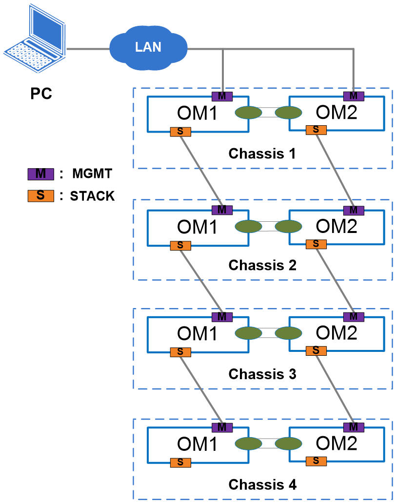
Figure 30 shows the networking in dual-channel cascading mode.
· Configure chassis 1 as the primary chassis, and chassis 2, chassis 3, and chassis 4 work as secondary chassis.
· Connect the management port of the OM module in chassis 1 to the management network.
· From chassis 1, connect the STACK interface of OM module 1 in the current chassis to the MGMT interface of OM module 1 in the next chassis. Connect the STACK interface of OM module 2 in the current chassis to the MGMT interface of OM module 2 in the next chassis. Connect chassis 3 and chassis 4 in the same way.
· For details about the positions of the STACK interfaces and MGMT interfaces, see "External interfaces."
Figure 31 Dual-channel cascading mode
Configuring other functions
For details about how to configure other functions, see the online help and typical configuration cases.
Firmware upgrade
For details about the procedure, see the related product upgrade guide.
