- Table of Contents
- Related Documents
-
| Title | Size | Download |
|---|---|---|
| 03-Appendix B LEDs and ports | 229.14 KB |
Appendix B Ports and LEDs
Ports
The AP provides the following ports:
· One console port
· Four 10/100/1000M Ethernet copper ports
· One 54 VDC power port
· One Uplink/PoE port
· One USB port
It provides also a reset button (RST).
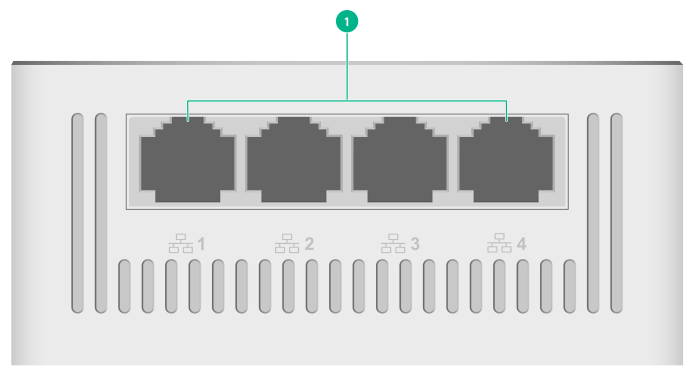
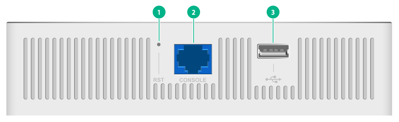
Figure 1 Ports on the AP
|
(1) 10/100/1000M Ethernet copper ports |
|
(1) Reset button (RST) |
(2) Console port |
(3) USB port |

|
(1) Uplink/PoE port |
(2) 54 VDC power port |
Table 1 Port descriptions
|
Port |
Standards and protocols |
Description |
|
Console port |
RS/EIA-232 |
Used by technical personnel only for device configuration and management. |
|
10/100/1000M Ethernet copper port |
· IEEE802.3 · IEEE802.3i · IEEE802.3u · IEEE802.3ab |
Represented by interface number GE1/0/2 to GE1/0/5 in the MAP file and GigabitEthernet 2 to GigabitEthernet 5 on the AC. |
|
Uplink/PoE port (10/100/1000M Ethernet copper port) |
· IEEE802.3 · IEEE802.3i · IEEE802.3u · IEEE802.3ab · IEEE802.3af · IEEE802.3at |
Used for connecting the AP to an uplink device for Internet or MAN access. It can also receive PoE power from the uplink device. It is represented by interface number GE1/0/1 in the MAP file and GigabitEthernet 1 on the AC. |
|
Power port (54 V) |
N/A |
Used for receiving +54 VDC power from a local power source. |
|
USB port |
USB 2.0 |
Used for charging as well as data reading or writing. |
|
Reset button |
N/A |
For more information, see Table 4. |
LEDs
The LED status varies by AP operating mode. For information about the supported operating modes, see the release notes for the AP.
Table 2 LED descriptions (fit mode)
|
LED |
Status |
Description |
|
|
Power status LED |
Off |
No power is present or the LED has been disabled from the CLI. |
|
|
Steady yellow |
The device is initializing or an initialization exception has occurred. |
||
|
Flashing green (once per two seconds) |
The AP has started up but has not registered to any AC. |
||
|
Flashing green (twice per second) |
The AP is upgrading the image. |
||
|
Steady green |
The AP has started up and registered to an AC, and is in standby state. |
||
|
Radio status LED |
Off |
The radios are disabled or the LED has been disabled from the CLI. |
|
|
Flashing yellow (once per second) |
A radio has been enabled but does not have associated clients. |
||
|
Flashing green (once per second) |
A radio has associated clients. |
||
|
Uplink port status LED |
Off |
No link is present on the port. |
|
|
Steady yellow |
The port has been auto-negotiated to operate at 10/100 Mbps. |
||
|
Flashing yellow |
The port is sending or receiving data at 10/100 Mbps. |
||
|
Steady green |
The port has been auto-negotiated to operate at 1000 Mbps. |
||
|
Flashing green |
The port is sending or receiving data at 1000 Mbps. |
||
|
Ethernet copper port LED |
Off |
No link is present on the port. |
|
|
Steady yellow |
The port has been auto-negotiated to operate at 10/100 Mbps. |
||
|
Flashing yellow |
The port is sending or receiving data at 10/100 Mbps. |
||
|
Steady green |
The port has been auto-negotiated to operate at 1000 Mbps. |
||
|
Flashing green |
The port is sending or receiving data at 1000 Mbps. |
||
Table 3 LED descriptions (cloud mode)
|
LED |
Status |
Description |
|
|
Power status LED |
Off |
No power is present or the LED has been disabled from the CLI. |
|
|
Steady yellow |
The device is initializing or an initialization exception has occurred. |
||
|
Flashing green (once per second) |
The AP has started up but has not registered to any AC. |
||
|
Flashing green (twice per second) |
The AP is upgrading the image. |
||
|
Alternating between yellow and green (once per second) |
The AP has connected to the Cloudnet platform and has associated clients. |
||
|
Radio status LED |
Off |
The radios do not have associated clients, or the LED has been disabled from the CLI. |
|
|
Flashing yellow (once per second) |
A radio has been enabled but does not have associated clients. |
||
|
Flashing green (once per second) |
A radio has associated clients. |
||
|
Uplink port status LED |
Off |
No link is present on the port. |
|
|
Steady yellow |
The port has been auto-negotiated to operate at 10/100 Mbps. |
||
|
Flashing yellow |
The port is sending or receiving data at 10/100 Mbps. |
||
|
Steady green |
The port has been auto-negotiated to operate at 1000 Mbps. |
||
|
Flashing green |
The port is sending or receiving data at 1000 Mbps. |
||
|
Ethernet copper port LED |
Off |
No link is present on the port. |
|
|
Steady yellow |
The port has been auto-negotiated to operate at 10/100 Mbps. |
||
|
Flashing yellow |
The port is sending or receiving data at 10/100 Mbps. |
||
|
Steady green |
The port has been auto-negotiated to operate at 1000 Mbps. |
||
|
Flashing green |
The port is sending or receiving data at 1000 Mbps. |
||
Table 4 RESET button descriptions
|
Press and hold duration (sec) |
Button LED status |
Description |
|
|
0 to 5 |
Steady green |
Reset the AP. |
|
|
5 to 20 |
Flashing green (twice per second) |
Restore to the factory defaults. |
|
|
20 to 30 |
Yellow |
Flashing (once per two seconds) |
The AP is operating in fit mode. |
|
Flashing (four times per second) |
The AP is operating in cloud mode. |
||
|
> 30 |
Yellow |
Flashing (twice per second) |
The AP is operating in cloud mode. |
|
Green |
Flashing (twice times per second) |
Change the AP operating mode to cloud. NOTE: If you release the button, the AP will restart for the new mode to take effect. |
|
