- Table of Contents
- Related Documents
-
| Title | Size | Download |
|---|---|---|
| 01-Text | 5.46 MB |
Introduction to system information
Introduction to fast configuration
Configure LAN interface settings
Create a static IP-MAC binding
Create multiple static IP-MAC bindings in bulk
Configure a time range group with only one type of time ranges
Configure a time range group that contains both periodic and absolute time ranges
Configure a network behavior management policy
Configure the website blacklist/whitelist
Configure a self-defined URL type
Introduction to signature database
Update signature database online
Configure application audit logs
Introduction to traffic ranking
Configure user traffic ranking
Configure application traffic ranking
Introduction to the firewall feature
Introduction to attack defense
Introduction to connection limit
Configure network connection limits
Configure VLAN-based network connection limits
Introduction to MAC address filter
Configure a MAC address filter
Add a whitelist or blacklist entry
Bulk add whitelist or blacklist entries
Introduction to ARP attack protection
Configure dynamic ARP learning
Configure dynamic ARP management
Configure attack protection management
Introduction to portal authentication
Configure the authentication page for Web page authentication
Configure the authentication page for WeChat client recognition
Add an authentication-free MAC address
Add an authentication-free IP address or host name
Configure the device as a branch node
Configure the device as a center node
Configure a VE-Bridge interface
Introduction to application services
Introduction to basic settings
Configure basic device information
Manually configure the system time
Automatically synchronize the UTC time
Collect diagnostic information
Configure the packet capture tool
About admin account management
Introduction to remote management
Configure HTTP login and HTTPS login
Introduction to configuration management
Save the running configuration
Restore configuration from a backup file
Export the running configuration
Restrictions and guidelines for license management
View features that require licenses
Send system log to a log server
View system log on the webpage
Configure an outgoing interface
Intelligent port identification
Replace a faulty device automatically
Replace a faulty member manually
Replace configuration manually
Products
H3C MSR router series includes the following series:
· H3C MSR 810 routers
· H3C MSR 830 routers
· H3C MSR 1000S routers
· H3C MSR 2600 routers
· H3C MSR 3600 routers
· H3C MSR 5600 routers
|
|
NOTE: For chassis views and installation methods for a product model, see the installation guide or hardware information and specifications for that product model. The Web pages vary by product series. The Web pages in this document are for illustration only. |
System information
Introduction to system information
System information allows you to obtain device operation information, use the wizard to configure basic settings, and obtain technology support.
View system information
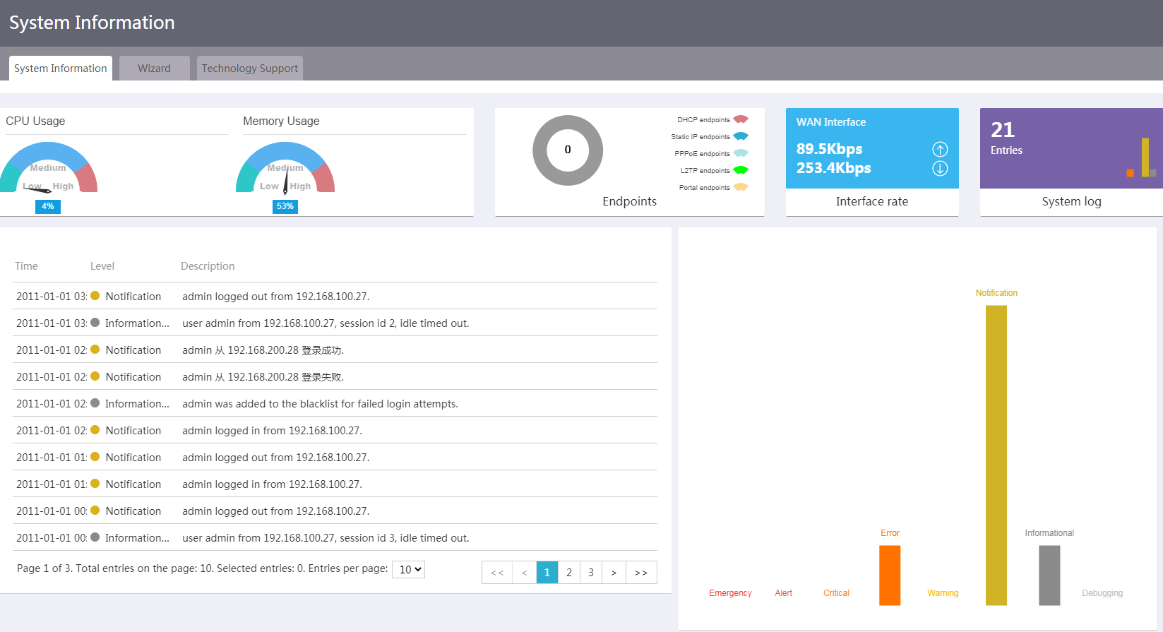
CPU usage and memory usage
Network configuration
Perform this task to view information about CPU usage and memory usage, including:
· Current and average CPU usage.
· Current and average memory usage.
Procedure
1. From the navigation pane, select System Information.
2. To view the current and average CPU usage or the current and average memory usage, click the CPU Usage or Memory Usage area, respectively.
Figure 1 Viewing CPU usage and memory usage
Endpoints
Network configuration
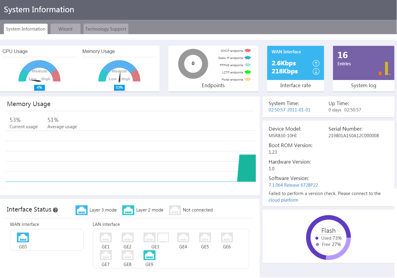
Perform this task to view information about endpoints that access the device, including:
· Top 5 endpoints by traffic rate.
· Number of online endpoints.
· Endpoint list, including endpoint IP address, endpoint name, username, access method, interface, and endpoint MAC address.
Procedure
1. From the navigation pane, select System Information.
2. Click the Endpoints area. You can view top 5 endpoints by traffic rate in real time.
3. To view user traffic ranking, click View more.
Figure 2 Viewing top 5 endpoints by traffic rate
Interface rate
Network configuration
Perform this task to view interface rate information, including uplink traffic, uplink rate, downlink traffic, downlink rate, WAN interface status, and network access parameters. You can also re-connect an interface or disconnect an interface, or refresh interface information.
Procedure
1. From the navigation pane, select System Information.
2. Click the Interface rate area.
3. To reconnect to an interface, click reconnect.
4. To disconnect an interface, click release.
System log
Network configuration
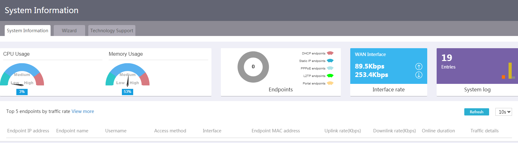
Perform this task to view system log information of the device, including:
· Log information of the device.
· Log statistics.
Procedure
1. From the navigation pane, select System Information.
2. Click the System log area.
Figure 3 Viewing system log
Device information
Network configuration
Perform this task to view device information, including the system time and device model.
Procedure
1. From the navigation pane, select System Information.
2. In the System Time area, you can view the system time and up time of the device. In the Device Model area, you can view the device model, serial number, Boot RoM version, hardware version, and software version.
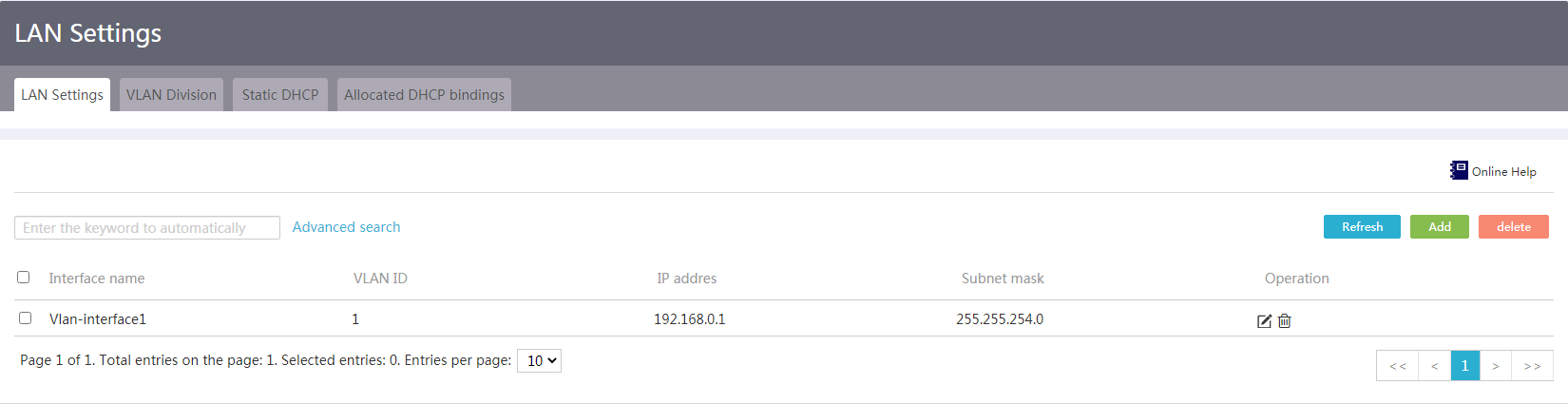
Interface status
Network configuration
Perform this task to view WAN interface status and LAN interface status.
Procedure
1. From the navigation pane, select System Information.
2. To view information about a WAN interface or LAN interface, click the interface icon in the Interface Status area to enter the WAN settings page or LAN settings page.
Figure 4 LAN Settings page
Storage medium
Network configuration
Perform this task to view the storage space usage of the storage medium.
Procedure
1. From the navigation pane, select System Information.
2. In the lower right corner of the page, you can view the storage space usage of the storage medium.
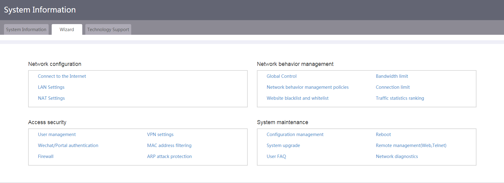
Use the wizard
To configure network settings quickly from the wizard:
1. From the navigation pane, select System Information.
2. Click the Wizard tab.
3. Click links to configure the following settings as needed:
¡ Network configuration:
- Connect to the Internet—Click the Connect to the Internet link to go to the WAN Settings page.
- LAN Settings—Click the LAN Settings link to go to the LAN Settings page.
- NAT Settings—Click the NAT Settings link to go to the NAT Settings page.
¡ Network behavior management:
- Global Control—Click the Global Control link to go to the Network Behaviors > Global Control page.
- Bandwidth limit—Click the Bandwidth limit link to go to the Bandwidth Management > Bandwidth limits page.
- Network behavior management policies—Click the Network behavior management policies link to go to the Network Behaviors > Network behavior management policy page.
- Connection limit—Click the Connection limit link to go to the Connection Limit > Connection Limits page.
- Website blacklist and whitelist—Click the Website blacklist and whitelist link to go to the Network Behaviors > Web blacklist and whitelist page.
- Traffic statistics ranking—Click the Traffic statistics ranking link to go to the Traffic Ranking > Global control page.
¡ Access security:
- User management—Click the User management link to go to the User Management > User Settings page.
- VPN settings—Click the VPN settings link to go to the IPsec VPN > IPsec policy page.
- Wechat/Portal authentication—Click the Wechat/Portal authentication link to go to the Portal Authentication > Authentication Settings page.
- MAC address filtering—Click the MAC address filtering link to go to the MAC Address Filter > MAC Filter Setting page.
- Firewall—Click the Firewall link to go to the Firewall page.
- ARP attack protection—Click the ARP attack protection link to the dynamic ARP learning settings page.
¡ System maintenance:
- Configuration management—Click the Configuration management link to go to the View Config page
- Reboot—Click the Reboot link to go to the Reboot now page.
- System upgrade—Click the System upgrade link to go to the Upgrade page.
- Remote management(Web,Telnet)—Click the Remote management(Web,Telnet) link to go to the Remote Login > Ping page.
- User FAQ—Click the User FAQ link to go to the User FAQ page.
- Network diagnostics—Click the Network diagnostics link to go to the Diagnostics > Tracert page.
Figure 5 Using the wizard
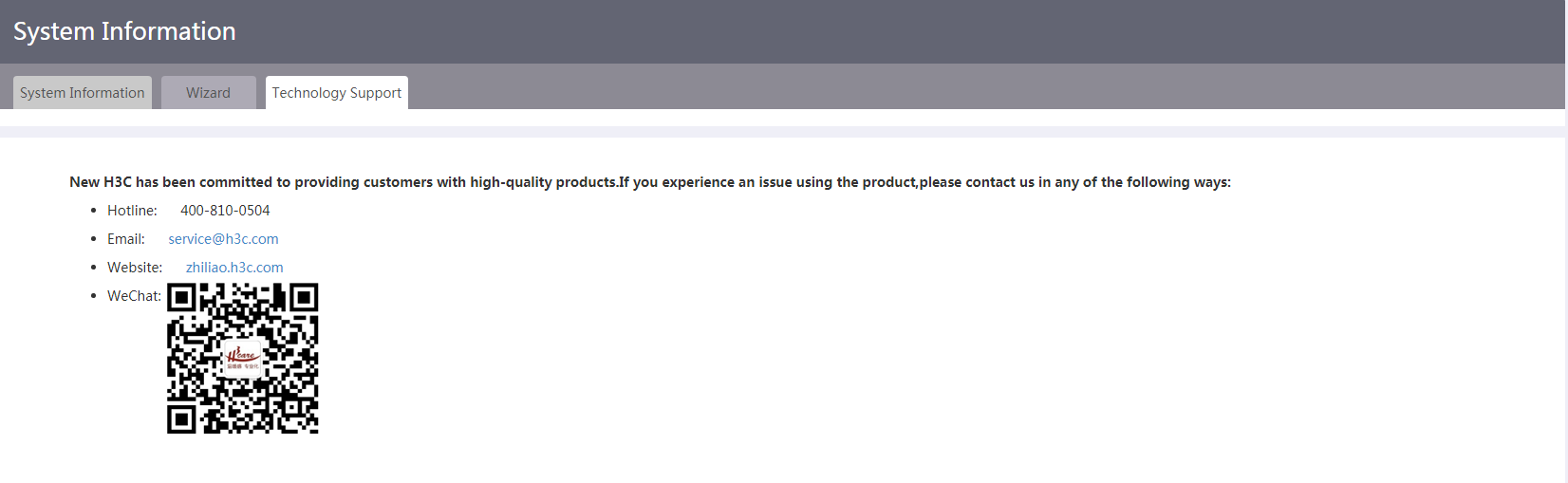
Obtain technology support
If you experience an issue using the product, you can obtain technology support in any of the following ways, as shown in Figure 6:
· Hotline: 400-810-0504.
· Email: [email protected].
· Website: zhiliao.h3c.com.
· WeChat official account.
Fast configuration
Introduction to fast configuration
Through fast configuration, you can fast complete basic WAN settings and LAN settings. Then, users in the LANs can access the WANs.
Configure WAN settings
Network configuration
The device supports the following WAN access scenarios:
· Single-WAN—If the user leases only one operator network, select the single-WAN scenario.
· Dual-WAN—If the user leases two operator networks, select the dual-WAN scenario.
The configuration procedure is the same for both scenarios.
The device can connect to a WAN through a physical interface or mobile communication (3G/4G) modem.
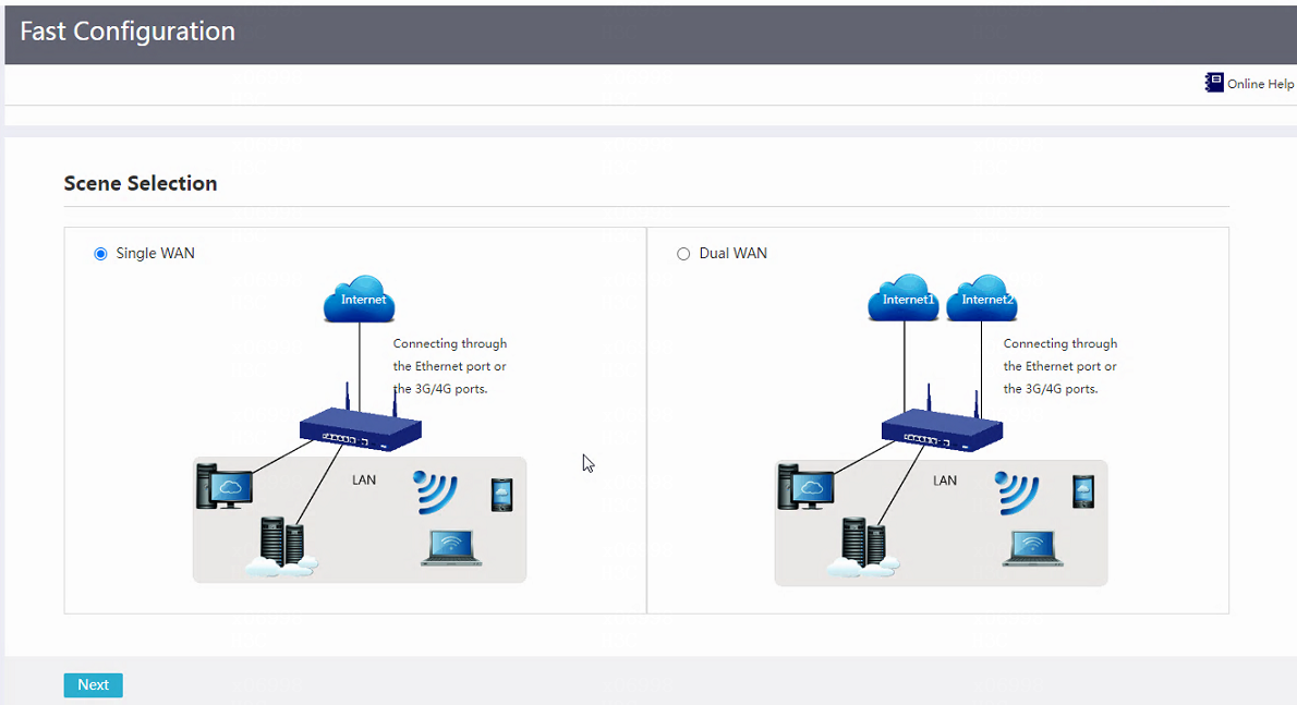
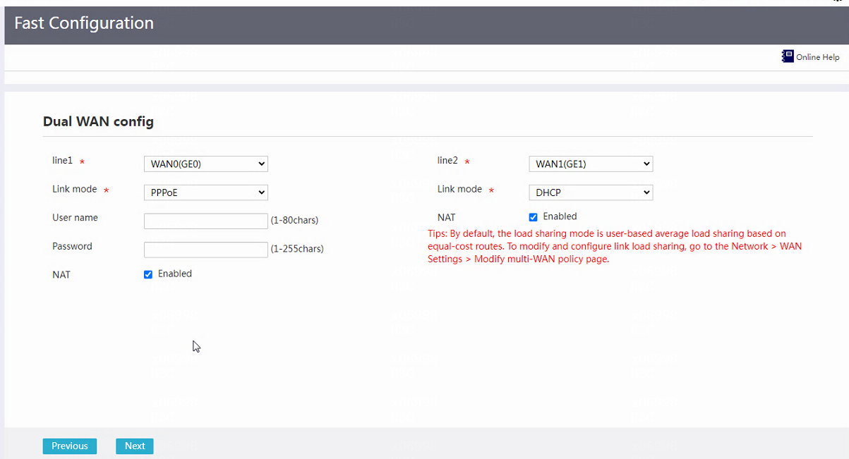
Connect to a WAN through a physical interface
1. From the navigation pane, select Fast Configuration.
2. Select the single-WAN and dual-WAN scenario as needed, and set the WAN access parameters.
Figure 7 Fast configuration: Selecting a scenario
3. From the Line 1 or Line 2 list, select the physical interface WANx for accessing the WAN.
4. From the Link mode list, select a link mode as needed.
¡ If you select the PPPoE link mode, perform the following tasks:
- In the Username field, enter the PPPoE access username provided by the operator.
- In the Password field, enter the PPPoE access password provided by the operator.
¡ If you select the DHCP link mode, the DHCP server automatically assigns the public IP addresses for accessing the WAN.
¡ If you select the fixed IP link mode, perform the following tasks:
- In the IP address field, enter the fixed IP address for accessing the WAN.
- In the IP mask field, enter the mask or mask length for the IP address, for example, 255.255.255.0 or 24.
- In the Gateway address field, enter the gateway address for accessing the WAN.
- In the DNS1 and DNS2 fields, enter the IP addresses for DNS servers for accessing the WAN. The device preferentially uses DNS server DNS1 for domain name translation. If DNS server DNS1 fails to translate a domain name, DNS server DNS2 is used.
5. For the NAT field, select whether to enable NAT.
Enable NAT when multiple devices in the LAN share one public IP.
6. Click Next to complete WAN settings.
Figure 8 Fast configuration: Single-WAN configuration

Figure 9 Fast configuration: Dual-WAN configuration
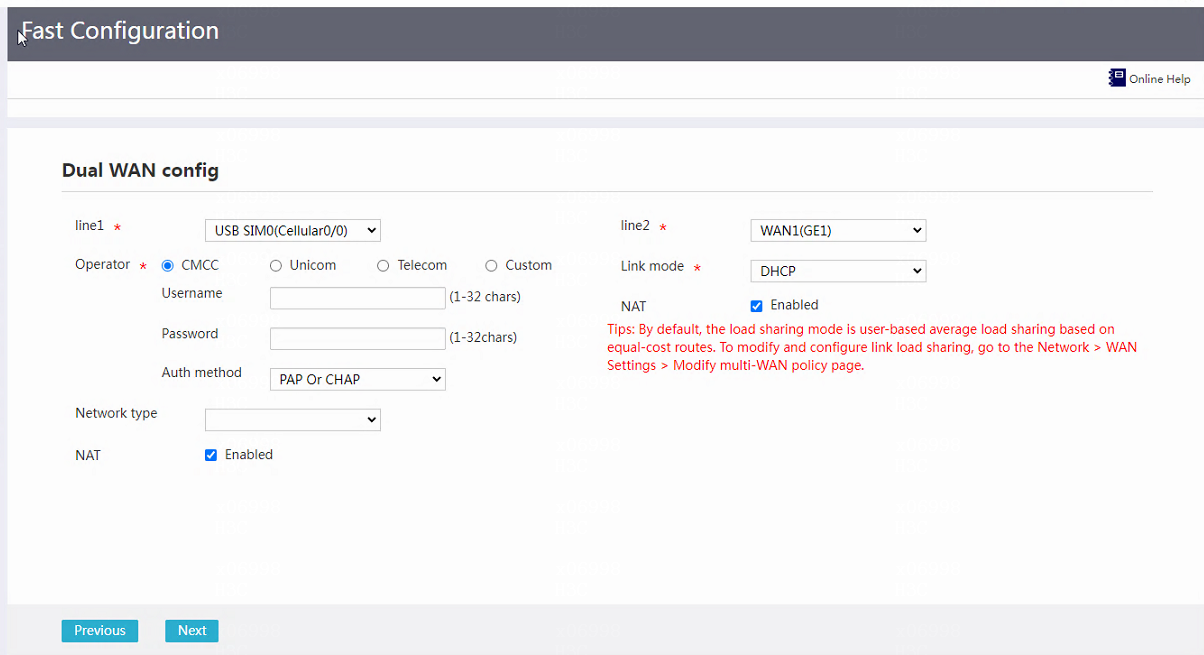
Connect to a WAN through a mobile communication (3G/4G) modem
1. From the navigation pane, select Fast Configuration.
2. Select the single-WAN and dual-WAN scenario as needed, and set the WAN access parameters.
3. From the Line 1 or Line 2 list, select the Cellular interface corresponding to the mobile communication modem.
¡ When the mobile communication modem is inserted into a USB interface, select interface USB SIM0(Cellular0/m).
¡ When the mobile communication modem is a modem embedded in a SIC module or the device, select the interface where the SIM card is inserted, SIMx(Cellularn/m).
4. For the Operator field, select an operator as needed.
Options are CMCC, Unicom, Telecom, and Custom.
¡ If you select CMCC, Unicom, or Telecom, perform the following tasks:
- In the Username field, enter the username provided by the operator.
- In the Password field, enter the password provided by the operator.
- In the Auth method field, select a user authentication method.
Options include PAP or CHAP, PAP, and CHAP. CHAP is more secure than PAP. If the network is insecure, select CHAP. For the device and the endpoint of the user to automatically negotiate the authentication method, select PAP or CHAP. For the authentication method to take effect, you must specify the username and password.
¡ If you select Custom, perform the following tasks:
- In the APN field, enter the APN provided by the operator.
- In the Dialer number field, enter the dialer number provided by the operator.
- In the Username field, enter the username provided by the operator.
- In the Password field, enter the password provided by the operator.
- In the Auth method field, select a user authentication method.
Options include PAP or CHAP, PAP, and CHAP. CHAP is more secure than PAP. If the network is insecure, select CHAP. For the device and the endpoint of the user to automatically negotiate the authentication method, select PAP or CHAP. For the authentication method to take effect, you must specify the username and password.
To use the SIM card of a non-domestic operator or an IoT operator, select Custom from the Operator list.
5. From the Network type list, select the network standard of the operator.
6. For the NAT field, select whether to enable NAT.
Enable NAT when multiple devices in the LAN share one public IP.
7. Click Next to complete WAN settings.
Figure 10 Fast configuration: Single-WAN configuration
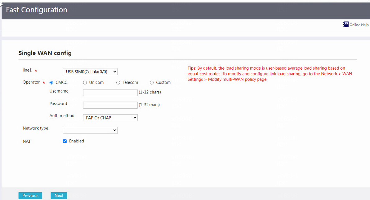
Figure 11 Fast configuration: Dual-WAN configuration
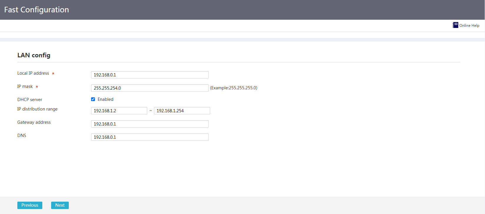
Configure LAN settings
After WAN settings are completed, the LAN settings page opens.
1. In the Local IP address field, enter the IP address used by the device in the LAN.
2. In the IP mask field, enter the mask or mask length for the IP address, for example, 255.255.255.0 or 24.
3. For the DHCP server field, select Enabled as needed. For the device to act as the DHCP server and allocate IP addresses to hosts in the LAN, select Enabled.
¡ After selecting Enabled, perform the following tasks:
- In the IP distribution range field, enter the start IP address and end IP address of the IP addresses to be allocated.
- In the Gateway address field, enter the gateway address that the device allocates to DHCP clients.
- In the DNS field, enter the DNS server IP address that the device allocates to clients.
¡ If you do not select Enabled, DHCP will not be enabled on the device.
4. Click Next to complete LAN settings.
Figure 12 Fast configuration: LAN configuration
Network
WAN settings
Introduction to WAN settings
A wide area network (WAN) provides telecommunication services over a large geographical area. The Internet is a huge WAN network.
Generally, a device provides multiple WAN interfaces for WAN network access.
Select a scenario
About this task
The device supports the following WAN access scenarios:
· Single-WAN scenario—Select this scenario if your network service is provided by only one Internet service provider.
· Multi-WAN scenario—Select this scenario if your network service is provided by two Internet service providers.
The configuration procedures for both scenarios are the same.
Procedure
1. From the navigation pane, select Network > WAN Settings.
The Scene tab is displayed by default.
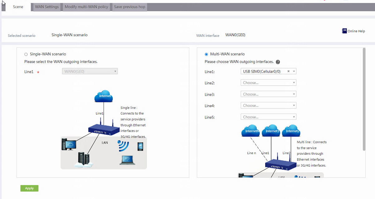
2. Select Single-WAN scenario or Multi-WAN scenario as needed.
3. Select one or multiple interfaces for WAN network access, which can be physical WAN interfaces or the cellular interface for the mobile communication modem.
¡ For the single-WAN scenario, select an interface for Line 1.
¡ For the multi-WAN scenario, select interfaces for Line 1, Line 2, Line 3, and Line 4.
When the mobile communication modem is inserted into a USB interface, select interface USB SIM0(Cellular0/m). When the mobile communication modem is a modem embedded in a SIC module or the device, select the interface where the SIM card is inserted, SIMx(Cellularn/m).
4. Click Apply.
Figure 13 Selecting a scenario
Configure WAN settings
About this task
You can use a physical interface or mobile communication (3G/4G) modem to access the WAN network.
Access the WAN network through a physical interface
1. From the navigation pane, select Network > WAN Settings.
2. Click the WAN Settings tab.
Figure 14 WAN settings

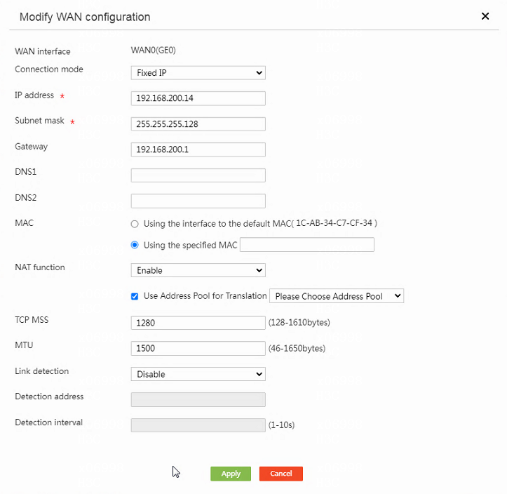
3. Click the edit icon for a line.
4. Select a connection mode. Options include PPPoE, DHCP, and Fixed IP.
¡ If you select PPPoE, configure the following parameters:
- In the User ID field, enter the username provided by the service provider.
- In the User password field, enter the password provided by the service provider.
- Select Always online for Online mode.
¡ If you select DHCP, the device will obtain a public IP address from the DHCP server for WAN access.
¡ If you select Fixed IP, configure the following parameters:
- In the IP address field, enter the fixed IP address.
- In the Subnet mask field, enter the subnet mask or subnet mask length, for example, 255.255.255.0 or 24.
- In the Gateway field, enter the gateway IP address.
- In the DNS1 and DNS2 fields, enter IP addresses of the primary DNS server and secondary DNS server, respectively. If the primary DNS server fails domain name resolution, the secondary DNS server is used.
5. Select Using the interface to the default MAC (XX-XX-XX-XX-XX-XX) or Using the specified MAC for MAC.
If you select Using the specified MAC, enter a MAC address. If you use an IP address assigned by the Internet service provider for WAN network access, configure a static MAC address.
6. Select whether to enable NAT.
Enable this feature if multiple devices on the LAN network share the same public IP address. To use an address pool for translation, select Use Address Pool for Translation, and select an address pool.
7. In the TCP MSS field, enter a MSS value.
8. In the MTU field, enter an MTU value.
9. Select whether to enable link detection.
This feature improves the link availability by detecting the link status to the specified IP address. If you enable this feature, configure the following parameters:
¡ In the Detection address field, enter an IP address for link detection.
¡ In the Detection interval field, enter the link detection interval.
10. Click Apply.
Figure 15 Modifying WAN configuration
Access the WAN network through a mobile communication (3G/4G) modem
1. From the navigation pane, select Network > WAN Settings.
2. Click the WAN Settings tab.
Figure 16 WAN settings

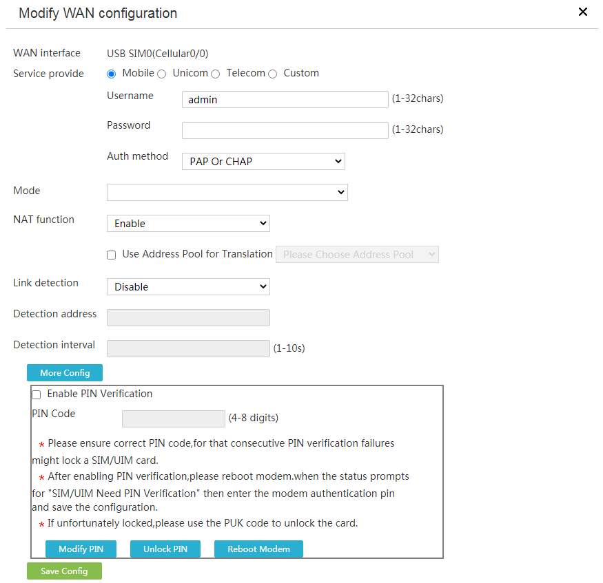
3. Click the edit icon for a line.
4. Select a service provider. Options include Mobile, Unicom, Telecom, and Custom.
¡ If you select Mobile, Unicom and Telecom, configure the following parameters:
- In the Username field, enter the username provided by the service provider.
- In the Password field, enter the password provided by the service provider.
- In the Auth method field, select a user authentication method.
Options include PAP or CHAP, PAP, and CHAP. CHAP is more secure than PAP. If the network is insecure, select CHAP. For the device and the endpoint of the user to automatically negotiate the authentication method, select PAP or CHAP. For the authentication method to take effect, you must specify the username and password.
¡ If you select Custom, configure the following parameters:
- In the APN field, enter the APN provided by the service provider.
- In the Dialer number field, enter the dial-up string provided by the service provider.
- In the Username field, enter the username provided by the service provider.
- In the Password field, enter the password provided by the service provider.
- In the Auth method field, select a user authentication method.
Options include PAP or CHAP, PAP, and CHAP. CHAP is more secure than PAP. If the network is insecure, select CHAP. For the device and the endpoint of the user to automatically negotiate the authentication method, select PAP or CHAP. For the authentication method to take effect, you must specify the username and password.
Select Custom if you use a SIM card of a foreign service provider or an IoT SIM card.
5. Select the network mode of the service provider for Mode.
6. Select whether to enable NAT.
Enable this feature if multiple devices on the LAN network share the same public IP address. To use an address pool for translation, select Use Address Pool for Translation, and select an address pool.
7. Select whether to enable link detection.
This feature improves the link availability by detecting the link status to the specified IP address. If you enable this feature, configure the following parameters:
¡ In the Detection address field, enter an IP address for link detection.
¡ In the Detection interval field, enter the link detection interval.
8. The Personal Identification Number (PIN) prevents the SIM card from being used by others. To configure the PIN code, click More Config and configure the following parameters:
¡ Select whether to enable PIN verification.
If you enable this feature, enter the PIN code. As a best practice, enable this feature to enhance the device security.
¡ To modify the PIN code, click Modify PIN, and then configure the following parameters:
- In the Current PIN Code field, enter the old PIN code.
- In the New PIN Code field, enter the new PIN code.
- In the Confirm New PIN Code field, enter the new PIN code again.
- To submit the modification, click Commit changes. To cancel the modification, click Back.
¡ To unlock the PIN code, click Unlock PIN, and then configure the following parameters:
- In the PUK Code field, enter the PUK code.
- In the New PIN Code field, enter the new PIN code.
- In the Confirm New PIN Code field, enter the new PIN code again.
- To unlock the PIN code, click Unlock. To cancel the modification, click Back.
¡ To reboot the mobile communication modem, click Reboot Modem.
9. Click Save Config.
Figure 17 Modifying WAN configuration
Modify multi-WAN policy
Restrictions and guidelines
This task is supported only in a multi-WAN scenario.
Procedure
1. From the navigation pane, select Network > WAN Settings.
2. Click the Modify Multi-WAN policy tab.
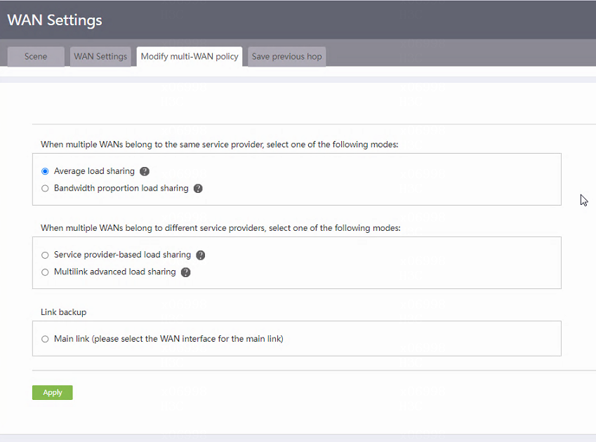
3. Modify the multiple-WAN policy as follows:
¡ If multiple WANs belong to the same service provider, select Average load sharing or Bandwidth proportion load sharing as a best practice.
- If the service provider provides the same bandwidth for all links, select Average load sharing.
- If link bandwidths are different, select Bandwidth proportion load sharing.
¡ If multiple WANs belong to different service providers, select Service provider-based load sharing or Multilink advanced load sharing as a best practice.
- If each service provider provides the same link bandwidth, select Service provider-based load sharing.
- If link bandwidths are different, select Multilink advanced load sharing.
¡ To ensure network stability, back up links as follows:
- Select Main link (please select the WAN interface for the main link), and then select a line.
- Select Backup link (please select the WAN interface for the backup link), and then select a line.
Make sure the lines for the main and backup links are different.
4. Click Apply.
Figure 18 Modifying multi-WAN policy
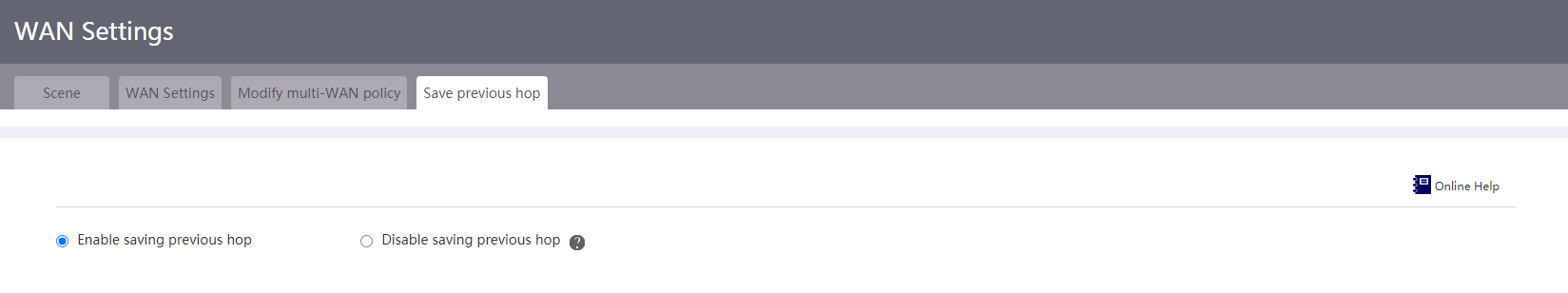
Save previous hop
1. From the navigation pane, select Network > WAN Settings.
2. Click the Save previous hop tab.
3. Select whether to enable saving the previous hop.
In a multi-WAN scenario, enable this feature to ensure that the packets originated from or destined for the LAN network is forwarded through the same WAN interface.
Figure 19 Saving previous hop
LAN settings
Introduction to LAN settings
Perform this task to configure a LAN interface for connecting to the internal network, enable DHCP, and assign the interface to VLANs.
DHCP is a LAN protocol mainly used for allocating IP addresses to hosts in a LAN. DHCP supports the following allocation mechanisms:
· Dynamic allocation—Configure this feature on an interface. This feature dynamically assigns IP addresses to hosts. After the lease of an IP address expires or an IP address is explicitly rejected by a host, the IP address can be used by another host. This allocation mechanism applies if you want to assign an IP address to a host for a limited period of time.
· Static allocation—Static IP addresses are not bound to interfaces, and they are bound to the host NIC MAC addresses. A static IP address can be used permanently. This allocation mechanism applies if you want to assign an IP address to a host permanently.
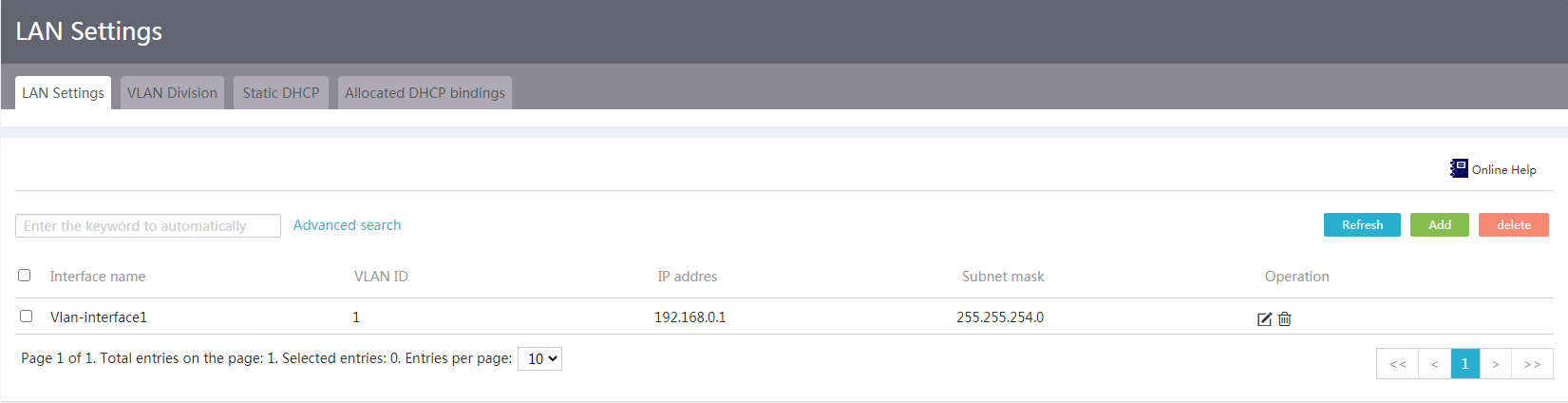
Configure LAN interface settings
Network configuration
Perform this task to configure an IP address for a GE interface connecting to the internal network or create a VLAN and its VLAN interface.
Procedure
1. From the navigation pane, select Network > LAN Settings.
2. Click the LAN Settings tab.
Figure 20 LAN settings
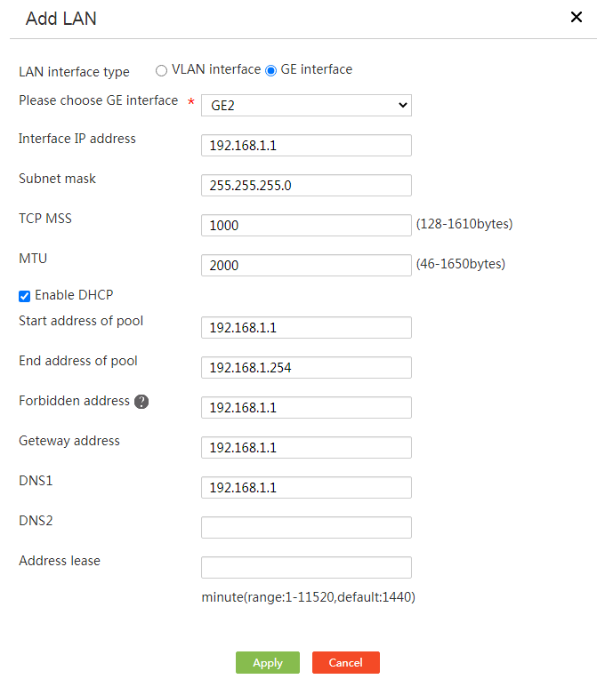
3. Click Add.
4. In the LAN interface type field, select an interface type.
¡ If you select VLAN interface, enter a VLAN ID to create a VLAN and its VLAN interface.
¡ If you select GE interface, select a GE interface.
5. In the Interface IP address field, enter an IP address for the interface.
6. In the Subnet mask field, enter the mask or mask length for the IP address, for example, 255.255.255.0 or 24.
7. In the TCP MSS field, configure the maximum segment size (MSS) of TCP packets for the interface.
8. In the MTU field, enter the MTU for the interface.
9. For the device to dynamically allocate IP addresses to connected clients (for example, computers), select Enable DHCP to enable DHCP on the device.
10. Click Apply.
Figure 21 Adding a LAN interface
Configure VLANs
Network configuration
Assign the LAN interfaces on the device to the specified VLAN, so that hosts in the same VLAN can communicate and hosts in different VLANs cannot directly communicate.
Restrictions and guidelines
When you configure a VLAN as the PVID for an interface on the detailed port configuration page, make sure the VLAN has already been created.
|
|
NOTE: The PVID identifies the default VLAN of a port. Untagged packets received on a port are considered as the packets from the PVID. |
Prerequisites
Plan the VLANs to which each LAN interface belongs on the device, and create the corresponding VLAN interface on the LAN interface configuration page.
Procedure
1. From the navigation pane, select Network > LAN Settings.
2. Click the VLAN Division tab.
Figure 22 VLAN division
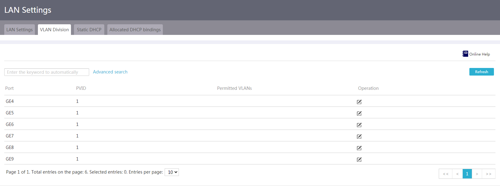
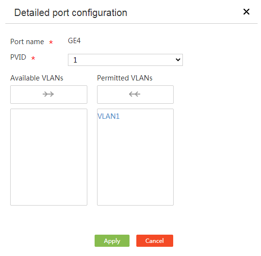
3. In the interface list, click the Edit icon for an interface. The detailed port configuration page opens.
4. In the PVID field, enter a PVID for the interface.
5. To assign an interface to or remove an interface from a VLAN:
¡ Click a VLAN ID in the available VLAN list to assign the interface to the VLAN, or click the rightward arrow icon above the available VLAN list to assign the interface to all available VLANs.
¡ Click a VLAN ID in the permitted VLAN list to remove the interface from the VLAN, or click the leftward arrow icon above the permitted VLAN list to remove the interface form all selected VLANs.
6. Click Apply.
Figure 23 Detailed port configuration
Enable DHCP on an interface
Network configuration
For the device to dynamically allocate IP addresses to clients (for example, computers) connected to the interface, enable DHCP on the interface.
Restrictions and guidelines
Make sure the address pool specified on the interface does not overlap with the WAN interface IP address range specified on the device.
Procedure
1. From the navigation pane, select Network > LAN Settings.
2. Click the LAN Settings tab.
3. Click the Edit icon for an interface.
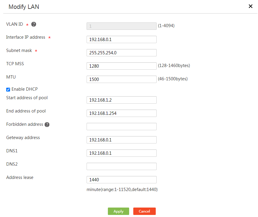
4. Select the Enable DHCP option.
5. In the Start address of pool and End address of pool fields, specify the range of IP addresses that DHCP can allocate to clients.
6. In the Forbidden address field, specify the IP addresses that cannot be allocated to clients.
If some IP addresses in the address range (for example, the gateway address) cannot be allocated to clients, specify these addresses as forbidden addresses.
7. In the Gateway address, DNS1, and DNS2 fields, enter the IP addresses of the gateway, primary DNS server, and secondary DNS server, respectively.
8. In the Address lease field, enter the lease (in minutes) of IP addresses to be allocated. For example, to specify the lease of IP addresses as five days, enter 7200.
9. Click Apply.
Figure 24 Editing a LAN interface
Create a static IP-MAC binding
Network configuration
To assign fixed IP addresses to some clients, configure static DHCP to bind client MAC addresses to IP addresses.
Restrictions and guidelines
Make sure static client IP addresses are not contained in the WAN interface IP address range specified on the device.
Prerequisites
Enable DHCP on any interface. To use only static DHCP to allocate IP addresses, you also need to delete DHCP settings on the interface.
Procedure
1. From the navigation pane, select Network > LAN Settings.
2. Click the Static DHCP tab.
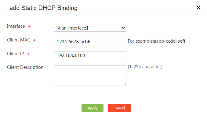
3. Click Add.
4. From the Interface list, select a DHCP-enabled interface.
5. In the Client MAC field, enter a client MAC address.
For a PC-type client, you can check the NIC information for its MAC address.
For a device-type client, execute the display interface command to obtain the MAC address of the interface.
6. In the Client IP field, enter the IP address to be allocated to the device.
7. Click Apply.
Figure 25 Creating a static IP-MAC binding
Create multiple static IP-MAC bindings in bulk
Restrictions and guidelines
To create static IP-MAC bindings in bulk, import the mappings between client MAC addresses and IP addresses.
Procedure
1. From the navigation pane, select Network > LAN Settings.
2. Click the Static DHCP tab.
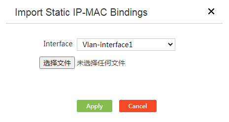
3. Click Import.
4. Select an interface that acts as a DHCP server from the Interface list.
5. Click Select File, and then select a file that stores static IP-MAC bindings.
|
|
NOTE: You can use Excel to make a static binding table. The table contains the following columns: IP ADDRESS, MASK, MAC ADDRESS, and DESCRIPTION (optional). After you configure the content of these columns as needed, save the table in CSV format. |
6. Click Apply.
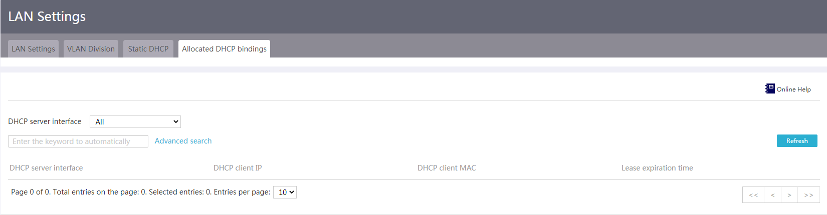
7. To view the IP addresses allocated to DHCP clients, click the Allocated DHCP bindings tab.
Figure 26 Importing static IP-MAC bindings
View allocated DHCP bindings
Prerequisites
After static or dynamic DHCP is configured on interfaces, you can view the IP addresses allocated to DHCP clients.
Procedure
1. From the navigation pane, select Network > LAN Settings.
2. Click the Allocated DHCP bindings tab.
3. Select an interface with DHCP server enabled from the DHCP server interface list to view the IP addresses assigned by the interface.
Figure 27 Allocated DHCP bindings
Port management
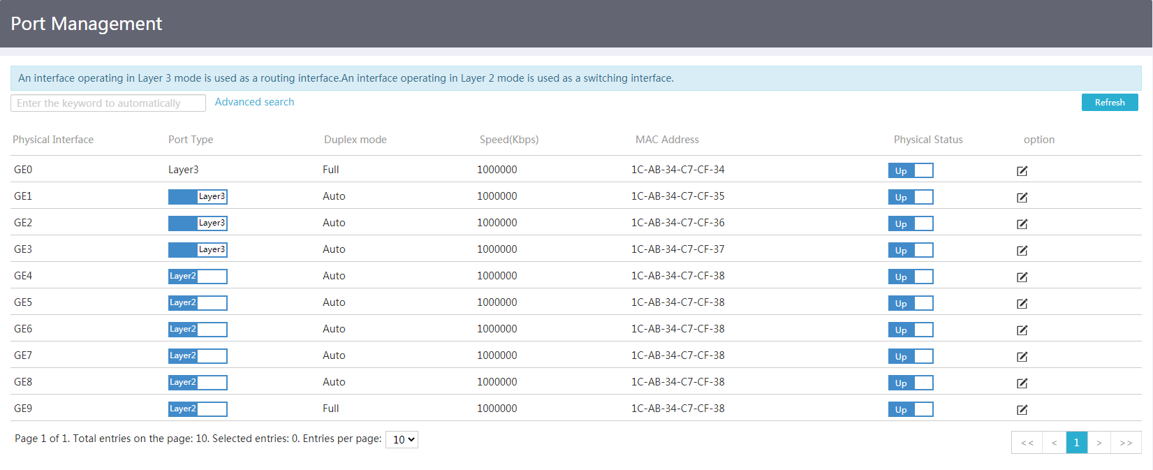
Introduction to port management
Port management allows you to view information about each physical port, including the port type, duplex mode, speed, and MAC address, change the physical status of ports, and modify the duplex mode and speed of ports.
Procedure
1. From the navigation pane, select Network > Port Management.
2. Click the toggle button in the Physical Status column to enable or disable a port.
Figure 28 Port management
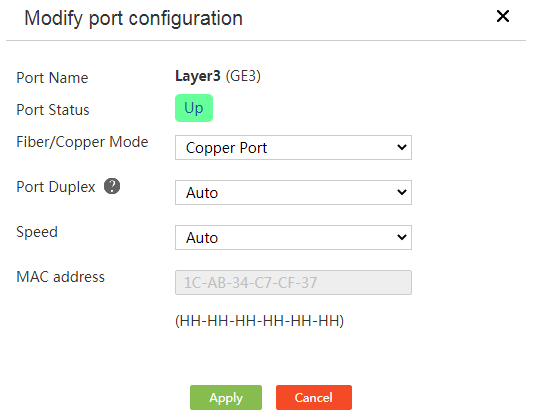
3. Click the Edit icon for a port.
4. Select a port mode from the Fiber/Copper Mode list.
5. Select a speed option from the Speed list.
6. View the MAC address of the port.
7. Click Apply.
Figure 29 Editing a port
NAT settings
Introduction to NAT
Network Address Translation (NAT) translates an IP address in the IP packet header to another IP address. It enables private hosts to access external networks and external hosts to access private network resources.
NAT supports the following address translation methods:
· Port mapping—Allows multiple internal servers (for example Web, mail, and FTP servers) to provide services to external hosts by using one public IP address and different port numbers. This method saves public IP address resources.
· One-to-one mapping—Creates a fixed mapping between a private address and a public address. Use this method for fixed network access requirements. This method is preferred if you need to use a fixed public IP address to access an internal server.
NAT provides the following advanced features:
· NAT hairpin—Allows internal users to access internal servers through NAT addresses. This feature is applicable if you want the gateway to control the internal user traffic destined for the internal server that provides services to external users through a public IP address.
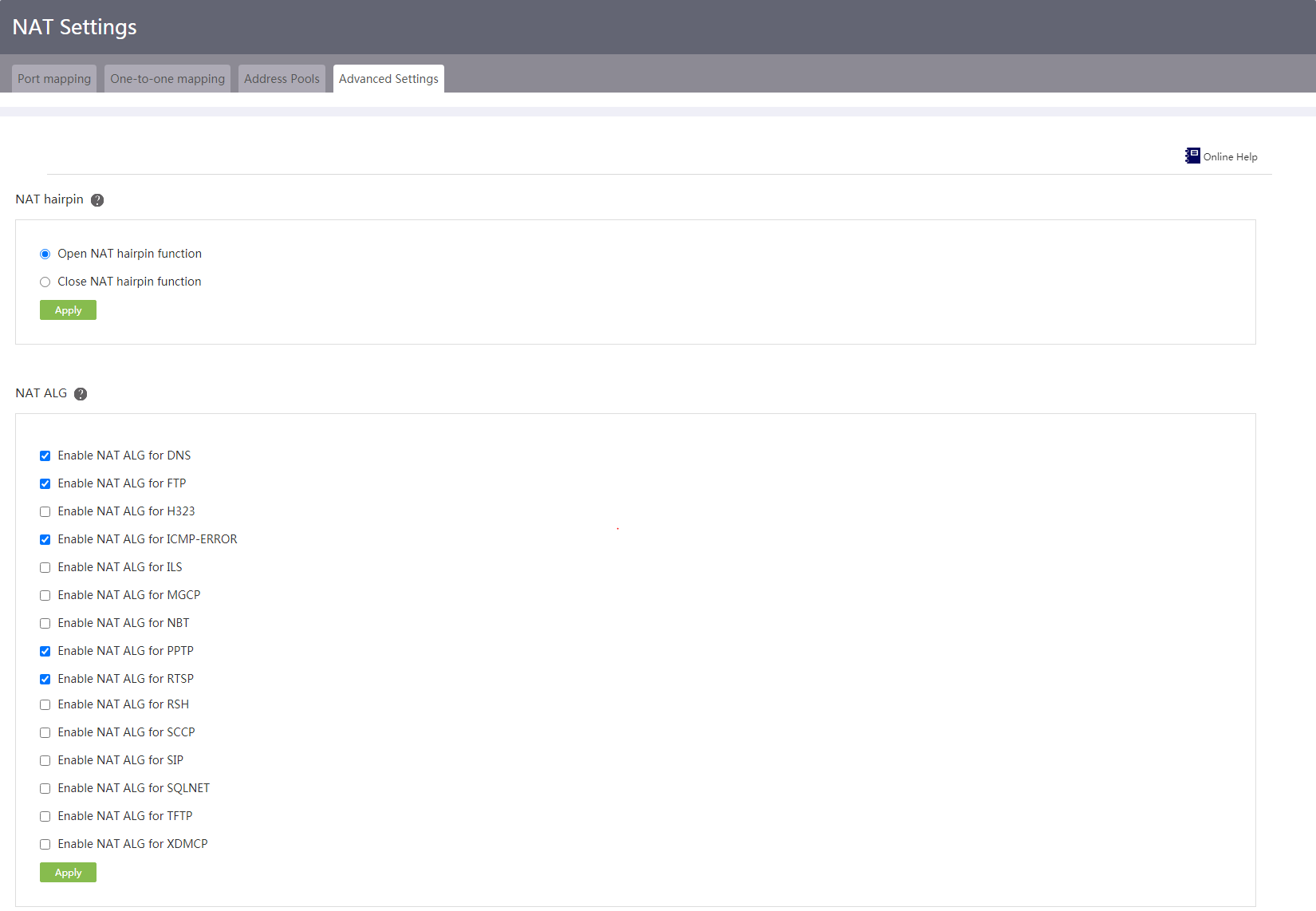
· NAT ALG—If an application layer service (for example, FTP or DNS) exists between the internal and external networks, enable NAT ALG for this application layer protocol. It ensures that the data connection of this protocol can be correctly established after address translation.
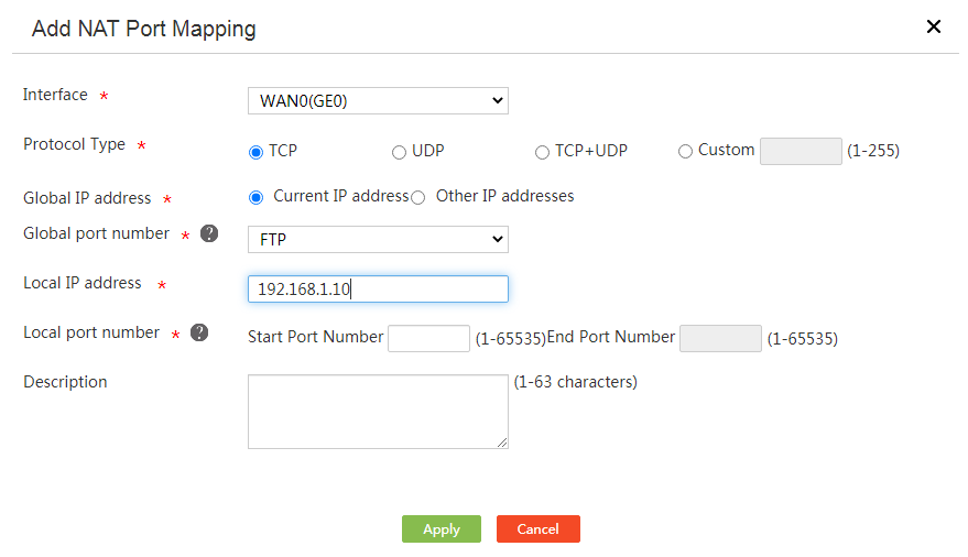
Configure port mapping
1. From the navigation pane, select Network > NAT Settings.
2. On the Port mapping tab, click Add.
3. Select the interface that connects to the Internet from the Interface list.
4. Select TCP, UDP, TCP+UDP, or Custom for Protocol Type.
Select the transport layer protocol that the internal server uses or enter a number that represents a transport layer protocol after selecting Custom. FTP servers use TCP and TFTP servers use UDP.
5. Select Current IP address or Other IP addresses for Global IP address.
6. Select FTP, Telnet, or User-defined ports from the Global port number list.
If the service provided by the internal server is not FTP or Telnet, enter the port number of the service, for example, port 80 for the HTTP server. If you have selected Custom for Protocol Type, this field cannot be configured.
7. In the Local IP address field, enter the private IP address of the internal server.
8. In the Local port number field, enter the port number of the internal server. If you have selected Custom for Protocol Type, this field cannot be configured.
9. Click Apply.
Figure 30 Adding a NAT port mapping
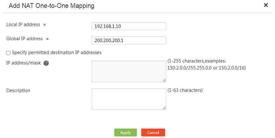
Configure one-to-one mapping
Restrictions and guidelines
As a best practice, do not configure a one-to-one mapping if the device has only one public IP address.
Procedure
1. From the navigation pane, select Network > NAT Settings.
2. Click the One-to-one mapping tab.
3. Click Add.
4. In the Local IP address field, enter an internal IP address.
5. In the Global IP address field, enter an external IP address.
6. Select Specify permitted destination IP addresses as required.
¡ If you select this option, enter destination IP addresses that can be accessed by internal users in the IP address/mask field. Address translation is performed on packets with the specified destination addresses.
¡ If you do not select this option, address translation is performed on all packets sent from the internal network to the external network.
7. Click Apply.
8. On the One-to-one mapping tab, select enable following OnetoOne mapping.
Figure 31 Adding a NAT one-to-one mapping
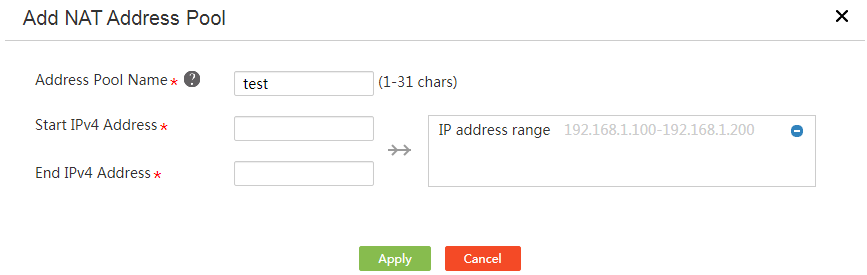
Configure NAT address pools
1. From the navigation pane, select Network > NAT Settings.
2. Click the Address Pools tab.
3. Click Add.
4. In the Address Pool Name field, enter an address pool name.
5. In the Start IPv4 Address field, enter the start IPv4 address.
6. In the End IPv4 Address field, enter the end IPv4 address.
7. Click the ![]() icon
to submit the address pool configuration.
icon
to submit the address pool configuration.
8. Repeat step 5 and step 6 to add multiple address ranges.
9. Click Apply.
Figure 32 Adding a NAT address pool
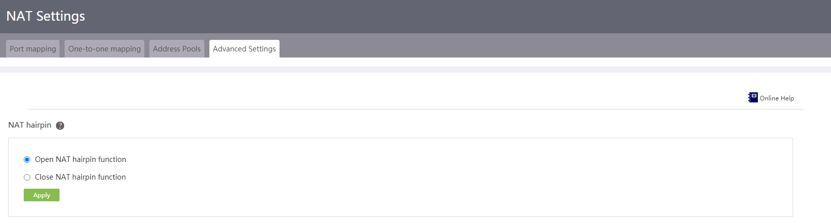
Configure NAT hairpin
Prerequisites
Before you configure NAT hairpin, configure a port mapping or one-to-one mapping.
Procedure
1. From the navigation pane, select Network > NAT Settings.
2. Click the Advanced Settings tab.
3. Select Open NAT hairpin function in the NAT hairpin area.
4. Click Apply.
Figure 33 Advanced settings-NAT hairpin
Configure NAT ALG
1. From the navigation pane, select Network > NAT Settings.
2. Click the Advanced Settings tab.
3. Enable NAT ALG for protocols.
4. Click Apply.
Figure 34 Advanced settings-NAT ALG
Network behavior management
User group
Introduction
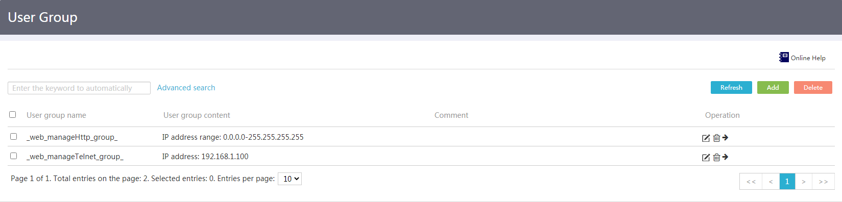
A user group is a group of host names or IP addresses. A user group can contain multiple members, and a member can be a host name, IP address, or IP address range. You can configure a user group to identify user packets for some services, such as bandwidth management.
Restrictions and guidelines
· The IP address member can only be an IPv4 address. IPv6 addresses are not supported.
· The start address in an IP address range must be lower than the end address.
Procedure
1. From the left navigation tree, select Network Behaviors> User Group.
Figure 35 User group
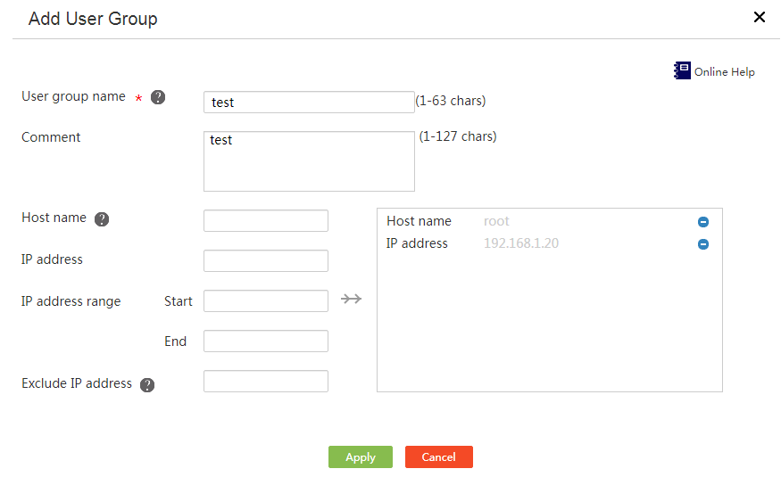
2. Click Add.
3. Enter a user group name in the User group name field.
4. Enter a user group description in the Comment field.
5. Configure members for the user group:
¡ Enter a host name to add to the user group.
¡ Enter an IP address to add to the user group.
¡ Enter a start address and an end address to specify an IP address range to add to the user group.
¡ Specify an IP address to exclude from the IP address range.
6. Click →→ to commit the configured members.
7. Repeat steps 5 and 6 to add multiple members of the same type.
8. Click Apply.
Figure 36 Adding a user group
Time range group
Introduction
If you want same features (for example, bandwidth management and network behavior management) to be effective only during a specific time period, you can configure a time range group and reference it for the related feature.
A time range group can contain multiple time ranges. The following types of time ranges are available:
· Periodic—Recurs periodically on a day or days of the week, for example, 8:00 to 12:00 every Monday.
· Absolute—Represents only a period of time and does not recur, for example, 8:00 on January 1, 2015 to 18:00 on January 3, 2015.
The active period of a time range group is calculated as follows:
· Combining all periodic statements.
· Combining all absolute statements.
· Taking the intersection of the two statement sets as the active period of the time range group.
Suppose you configure the following time ranges:
· Periodic time range: 08:30 to 12:00 and 13:30 to 18:00 on Monday through Friday.
· Absolute time range: 10:00 to 12:00 and 14:00 to 16:00 on April 1, 2015 through April 30, 2015.
The active period is 10:00 to 12:00 and 14:00 to 16:00 on Monday through Friday during April 1, 2015 through April 30, 2015.
Restrictions and guidelines
· You can create a maximum of 1024 time ranges, each with a maximum of 32 periodic time ranges and 12 absolute time ranges.
· You cannot configure the same time range group from both the CLI and the Web interface.
Configure a time range group with only one type of time ranges
Restrictions and guidelines
Perform this task to configure a time range group that contains only periodic or absolute time ranges.
Procedure
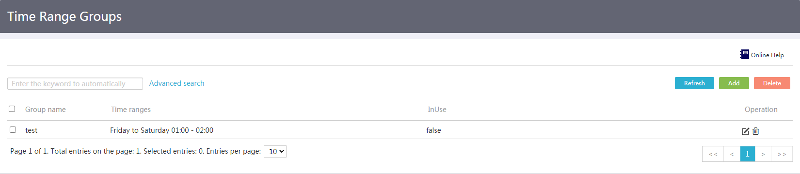
1. From the left navigation tree, select Network Behaviors> Time Range Group.
Figure 37 Time range group
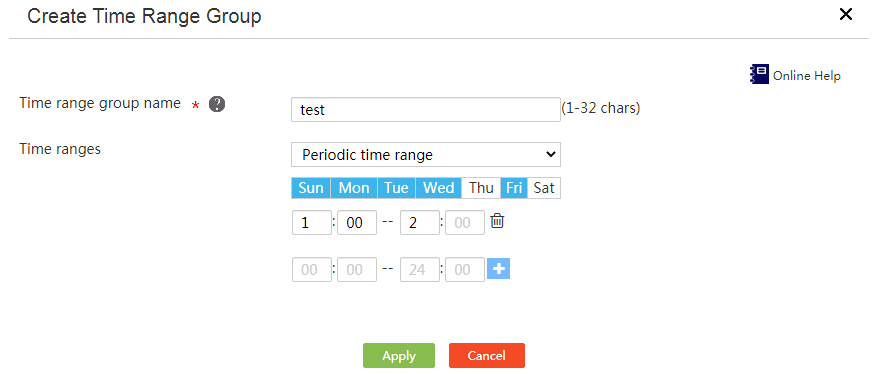
2. Click Add.
3. Enter a time range group name in the Time range group name field.
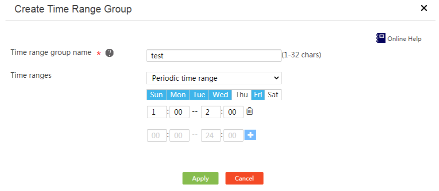
4. From the Time ranges list, select Periodic time range or Absolute time range, and configure a periodic time range or absolute time range.
¡ To configure a periodic time range, select the days of the week, enter the start time and end time, and click the plus sign.
¡ To configure an absolute time range, select the start date and end date, enter the start time and end time, and click the plus sign.
5. Click Apply.
Figure 38 Configuring a time range group with only one type of time ranges
Configure a time range group that contains both periodic and absolute time ranges
Restrictions and guidelines
Perform this task to configure a time range group that contains both periodic and absolute time ranges.
Procedure
1. From the left navigation tree, select Network Behaviors> Time Range Group.
2. Click Add.
3. Enter a time range group name in the Time range group name field.
4. Configure time ranges.
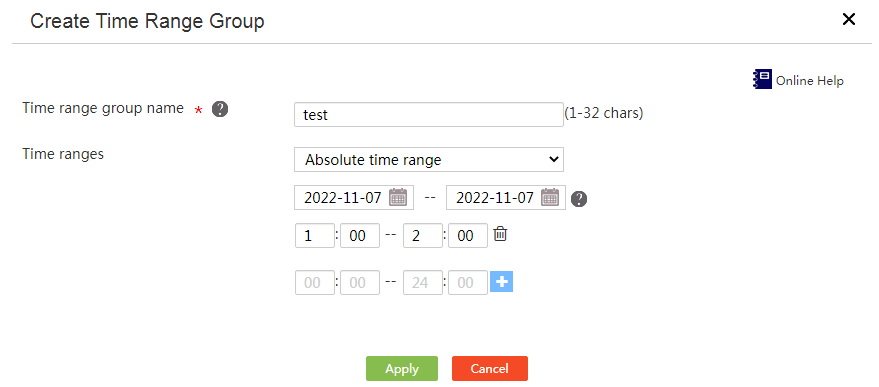
¡ Select Periodic time range from the Time ranges list. Select the days of the week, enter the start time and end time, and click the plus sign.
Figure 39 Configuring a periodic time range
¡ Select Absolute time range from the Time ranges list. Select the start date and end date, enter the start time and end time, and click the plus sign.
Figure 40 Configuring an absolute time range
5. Click Apply.
Edit a time range group
Restrictions and guidelines
Perform this task to remove periodic or absolute time ranges from a time range group that contains both periodic and absolute time ranges.
Procedure
1. From the left navigation tree, select Network Behaviors> Time Range Group.
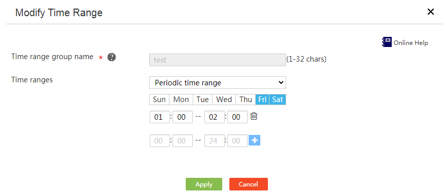
2. Click Edit in the Operation column for a time range group.
3. From the Time ranges list, select Periodic time range or Absolute time range.
4. Click the delete icon after each time range.
5. Click Apply.
Figure 41 Editing a time range group
Bandwidth management
Introduction
Bandwidth management can limit traffic rates and provides fine-grained control over traffic based on criteria such as user groups and time ranges.
For delay-sensitive interactive traffic, you can enable the green channel to guarantee bandwidth for it.
Configure bandwidth limits
Procedure
1. From the navigation tree, select Network Behaviors > Bandwidth Management.
Figure 42 Bandwidth limits
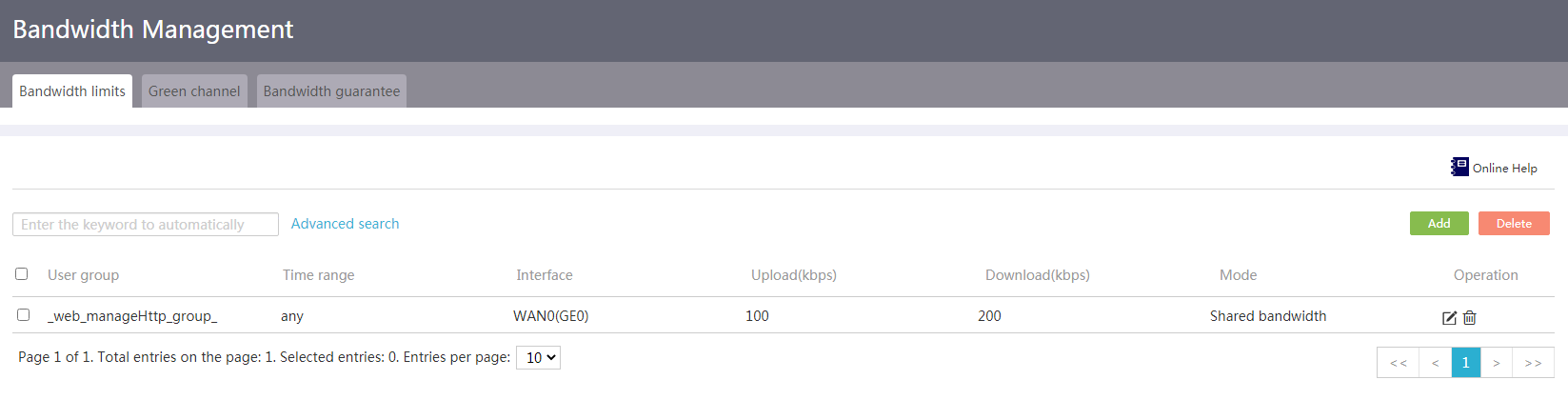
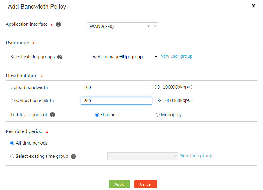
2. On the Bandwidth limits tab, click Add. The Add Bandwidth Policy page opens.
¡ Select an interface from the Application Interface list. The device performs bandwidth management on the selected interface.
¡ In the User range area, select a user group from the Select existing groups list. The device performs bandwidth management on the users in the selected user group.
¡ In the Flow limitation area, configure the upload bandwidth and download bandwidth, and select a bandwidth allocation method. If you do not specify the upload bandwidth or download bandwidth, the device does not limit the upload bandwidth or download bandwidth used.
Bandwidth allocation methods include:
- Sharing—The specified bandwidth is evenly distributed among all users.
- Monopoly—The specified bandwidth is exclusively used by a single user.
¡ In the Restricted period area, select a time range group.
3. Click Apply.
Figure 43 Adding a bandwidth policy
Configure the green channel
Restrictions and guidelines
To avoid affecting normal traffic, do not set too large a rate value for the green channel.
Procedure
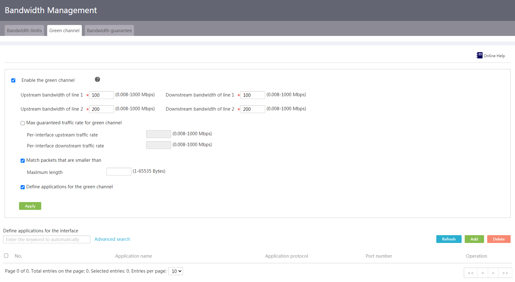
1. From the navigation tree, select Network Behaviors > Bandwidth Management.
2. Click the Green channel tab.
3. Select Enable the green channel.
4. Configure the application's protocol number and port number for delay-sensitive interactive traffic. Only the traffic matching the application is transmitted over the green channel.
a. Select Define applications for the green channel, and click Add.
b. Configure the application name, protocol number, and port number.
c. Click Apply.
5. Configure the following limit parameters for all defined applications:
¡ To limit the traffic rate to the same value for all WAN interfaces, select Bandwidth upper limit for the green channel, and set the maximum upstream or downstream traffic rate.
¡ To limit the traffic rate to the different values for different WAN interfaces, deselect Bandwidth upper limit for the green channel, and set the maximum upstream or downstream traffic rate for each WAN interface.
¡ To limit the maximum packet length, select Match packets that are smaller than, and set the maximum packet length. Packets exceeding the maximum packet length are not transmitted over the green channel.
6. Click Apply.
Figure 44 Green channel
Configure bandwidth guarantee
Restrictions and guidelines
A bandwidth guarantee policy for an interface can take effect only if the output bandwidth of the interface is set.
Only one bandwidth guarantee policy can be configured for an interface. Multiple match rules can be configured for a bandwidth guarantee policy. Multiple match criteria can be configured in a match rule. The guaranteed bandwidth is the total bandwidth used by all matching users.
Procedure
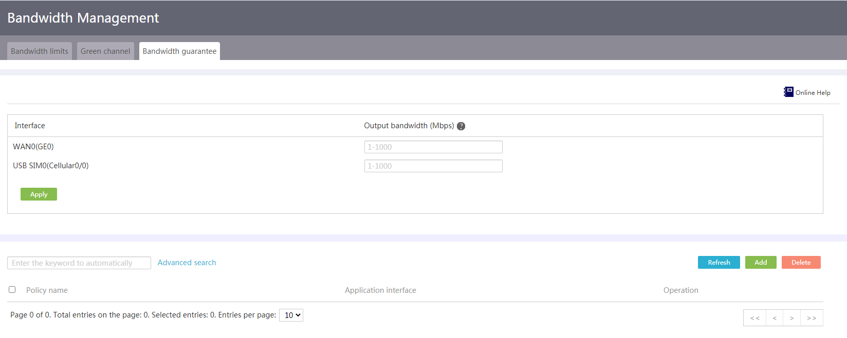
1. From the navigation tree, select Network Behaviors > Bandwidth Management.
2. Click the Bandwidth guarantee tab.
3. Configure the output bandwidth of the interface:
¡ Enter the actual link bandwidth provided by the service provider in the Output bandwidth (Mbps) field.
¡ Click Apply.
Figure 45 Bandwidth guarantee
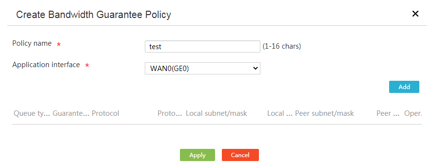
4. Configure a bandwidth guarantee policy for the interface:
¡ Click Add. The Create Bandwidth Guarantee Policy dialog box appears.
¡ Enter a policy name in the Policy name field.
¡ From the Application interface list, select an interface to apply the policy.
Figure 46 Configuring a bandwidth guarantee policy
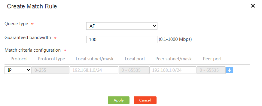
¡ Click Add. The Create Match Rule dialog box appears.
¡ From the Queue type list, select EF or AF. EF has higher forwarding priority than AF.
¡ Enter the total bandwidth used by all matching users in the Guaranteed bandwidth field.
¡ In the Match criteria configuration area, select a protocol name or enter a protocol number, configure the local subnet/mask and local port number, configure the peer subnet/mask and peer port number, and click the + icon.
¡ Click Apply.
5. In the Create Bandwidth Guarantee Policy dialog box, click Apply.
Figure 47 Creating a match rule
Network behavior management
Introduction
Network behavior management controls what applications and websites users can access and provides grain-fined control on network behaviors based on the user group and time range.
Configure global control
About this task
Perform this task to make network behavior management policies and URL filtering take effect.
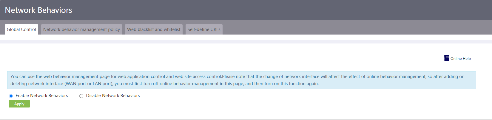
Procedure
1. From the navigation tree, select Network Behaviors > Network Behaviors.
2. On the Global control tab, select Enable Network Behaviors.
3. Click Apply.
Figure 48 Global control
Configure a network behavior management policy
Restrictions and guidelines
URL filtering is based on HTTP. For URL filtering to work correctly, do not block HTTP.
Procedure
1. From the navigation tree, select Network Behaviors > Network Behaviors.
Figure 49 Network behavior management policy
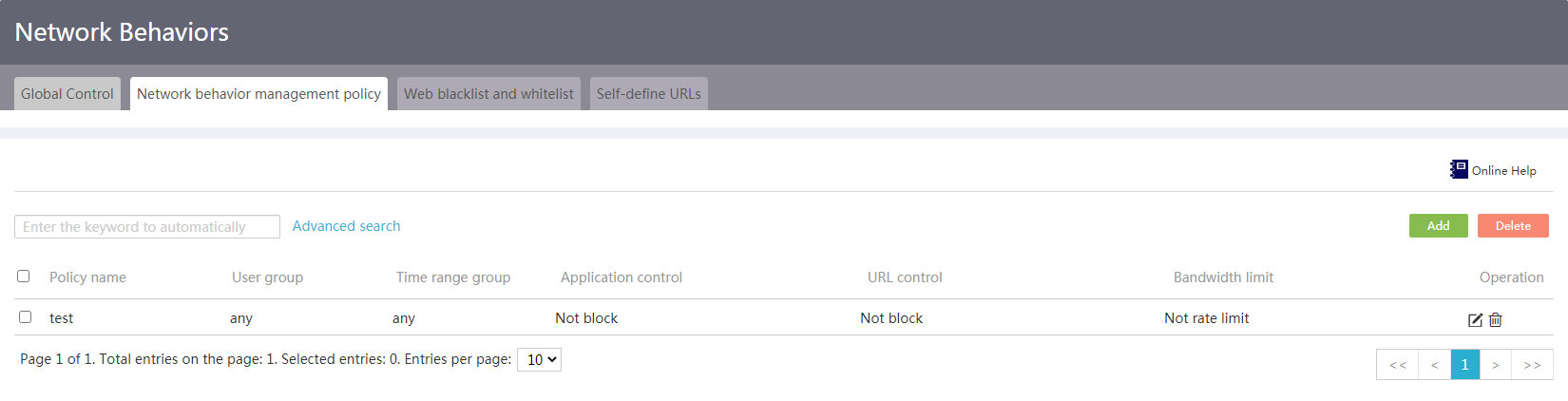
2. Click the Network behavior management policy tab.
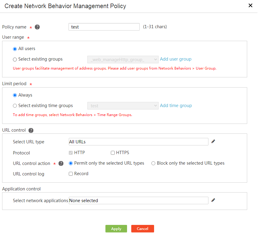
3. Click Add, and configure the following parameters:
¡ Enter a policy name in the Policy name field.
¡ In the User range area, select a user group.
¡ In the Limit period area, select a time range group.
¡ In the URL control area, configure the following settings:
- Select URL types—Select predefined URL types and self-defined URL types. For information about configuring self-defined URLs, see "Configure a self-defined URL type".
- Protocol—Select a protocol type: HTTP or HTTPS. By default, HTTPS is selected.
- URL control action—Select a URL control action. You can select the Record action together with the Permit or Deny action to record information about permit or deny behaviors.
¡ In the Application control area, click the Details icon to the right of Select network applications to select applications, and configure one of the following actions for the applications:
- Block—Deny access to the applications.
- No blocking or rate limit—Permit access to the applications without a rate limit.
- Rate limit—Permit access to the applications with a rate limit. Click the edit icon to set the maximum uplink bandwidth and maximum downlink bandwidth.
4. Click Apply.
5. Click the Global control tab, and select Enable Network Behaviors to make the new policy take effect.
Figure 50 Configuring a network behavior management policy
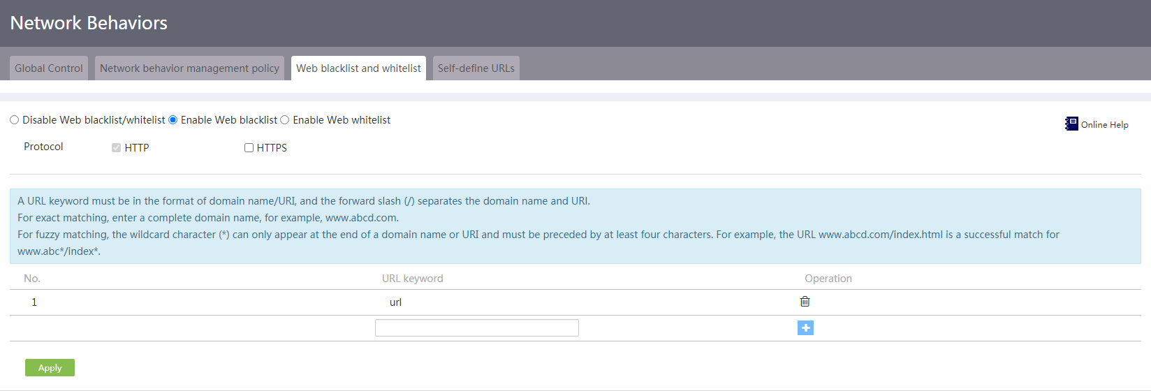
Configure the website blacklist/whitelist
About this task
Perform this task to permit or block access to specific URLs.
Procedure
1. From the navigation tree, select Network Behaviors > Network Behaviors.
2. Click the Web blacklist and whitelist tab.
3. Select Enable Web blacklist or Enable Web whitelist.
4. Select the protocol type to be supported. Options include HTTP and HTTPS. By default, HTTP is selected.
5. Enter a URL in the URL keyword field and click the plus sign to add the URL.
6. Repeat step 4 to add more URLs.
7. Click Apply to complete the configuration of the blacklist or whitelist.
Figure 51 Configuring the website blacklist/whitelist
Configure a self-defined URL type
About this task
Perform this task when predefined URL types cannot meet your requirements.
Restrictions and guidelines
You can export self-defined URLs. If an Excel start error occurs when you use the Internet Explorer browser to export URLs, modify the IE settings as follows:
1. On the IE toolbar, click the Tools button and select Internet Options.
2. Click the Security tab, and click Custom level….
3. In the ActiveX controls and plug-ins section, select Enable for Initialize and script ActiveX controls not marked as safe for scripting.
Procedure
1. From the navigation tree, select Network Behaviors > Network Behaviors.
Figure 52 Self-defined URL
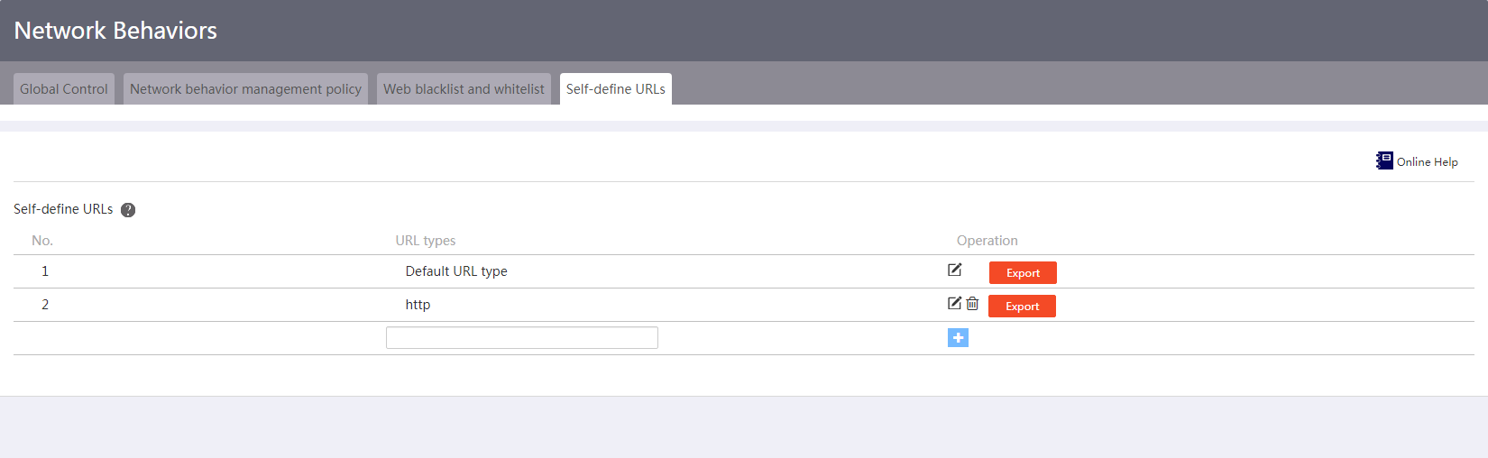
2. Click the Self-define URLs tab.
3. Enter a URL type and click the plus sign.
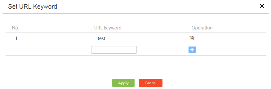
4. Click the edit icon to add URLs to the URL type.
5. Enter a URL and click the plus sign to add the URL.
6. Repeat step 5 to add more URLs.
7. Click Apply.
Figure 53 Setting a URL keyword
Signature database
Introduction to signature database
The device uses signatures to identify application layer traffic. The device supports application signature database and URL signature database. You can update signature databases to the latest version.
The following methods are available for updating signature databases on the device:
· Import signatures.
You must manually download the most up-to-date signature file, and then use the file to update the signature databases on the device.
· Update online.
The device automatically downloads the most up-to-date the signature file to update its signature databases after you trigger the operation.
Restrictions and guidelines
· Make sure a license is installed and is valid before updating the signature databases.
· Do not perform the signature database update when the device's free memory is below the normal state threshold. Otherwise, a failure of signature database update will affect network behavior management.
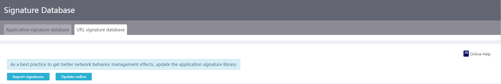
Import signatures
1. From the navigation pane, select Network Behaviors > Signature Database.
Figure 54 Application signature database
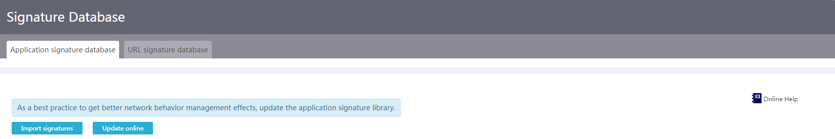
2. On the Application signature database or URL signature database tab, click Import signatures.
3. On the page that opens, select a signature file.
4. Click Apply.
Figure 55 URL signature database
Update signature database online
Restrictions and guidelines
For successful online signature database update, make sure the device can resolve the domain name of the official website into an IP address through DNS.
Procedure
1. From the navigation pane, select Network Behaviors > Signature Database.
2. On the Application signature database or URL signature database tab, click Update online.
Audit log
Introduction to audit log
The audit log feature allows you to view logs generated for application control and URL control functions. The logs help you perform network behavior auditing and analysis.
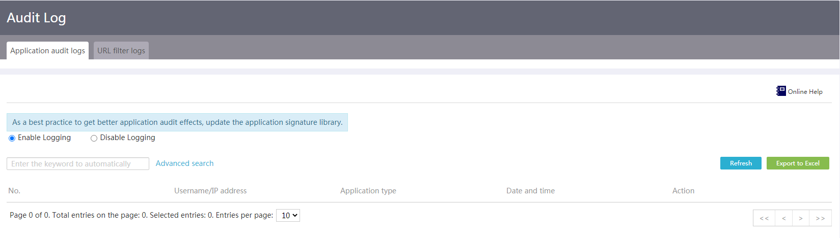
Configure application audit logs
1. From the navigation pane, select Network Behaviors > Audit Log.
2. On the Application audit logs tab, select Enable Logging.
3. On the Application audit logs tab, you can view the application audit logs. To export the logs, click Export to Excel.
Figure 56 Application audit logs
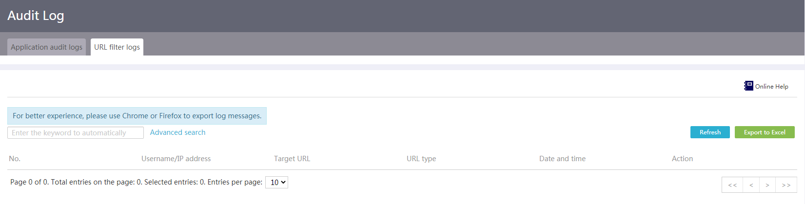
Configure URL filter logs
1. From the navigation pane, select Network Behaviors > Audit Log.
2. On the Application audit logs tab, select Enable Logging.
3. Click the URL filter logs tab.
4. On the URL filter logs tab, you can view the URL filter logs. To export the logs, click Export to Excel.
Figure 57 URL filter logs
Traffic ranking
Introduction to traffic ranking
On the Global control tab, you can enable or disable user traffic ranking and application traffic ranking.
· If user traffic ranking is enabled, you can view the user traffic data on the User traffic ranking tab.
· If application traffic ranking is enabled, you can view the application traffic data on the Application traffic ranking tab.
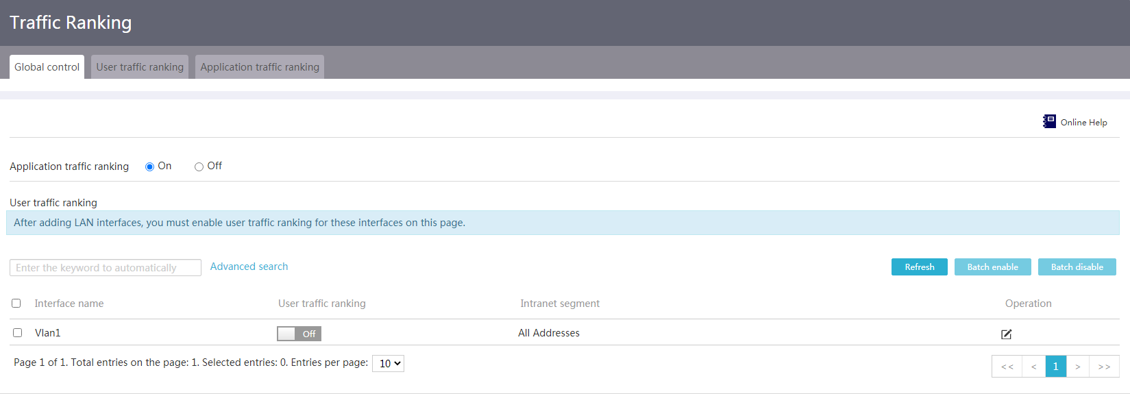
Configure global control
Restrictions and guidelines
· After adding LAN interfaces, you must enable user traffic ranking for these interfaces on this page.
· If portal configuration exists on an interface, the name of the interface is not displayed on the Global control tab. After you delete the portal configuration from the interface, the interface can be displayed on the Global control tab.
Procedure
1. From the navigation pane, select Network Behaviors > Traffic Ranking.
2. On the Global control tab, to enable application traffic ranking, select On following Application traffic ranking. To disable application traffic ranking, select Off following Application traffic ranking.
3. On the interface list, you can click the On/Off button for an interface to disable or enable static IP and DHCP user traffic ranking on the interface. Alternatively, you can select multiple interfaces and click Batch enable in the upper right corner to enable static IP and DHCP user traffic ranking on these interfaces. Also, you can select multiple interfaces and click Batch disable in the upper right corner to disable static IP and DHCP user traffic ranking on these interfaces.
4. Click the Edit icon in the Operation column for an interface. The Add intranet segment page opens. The system performs traffic statistics and ranking only for IP addresses within the intranet segment. The default intranet segment is the network segment directly connected to the interface. To ensure network connectivity, you must correctly configure the intranet segment. If the intranet segment changes, edit it promptly.
¡ The interface name displays the name of the interface that you are editing. You cannot edit the interface name.
¡ Configure a single IP address to be added to the intranet segment.
¡ Configure the start IP address and end IP address of an IP address range to be added to the intranet segment.
5. Click the ![]() icon to add the
configuration to the intranet segment.
icon to add the
configuration to the intranet segment.
6. Click Apply.
Figure 58 Global control
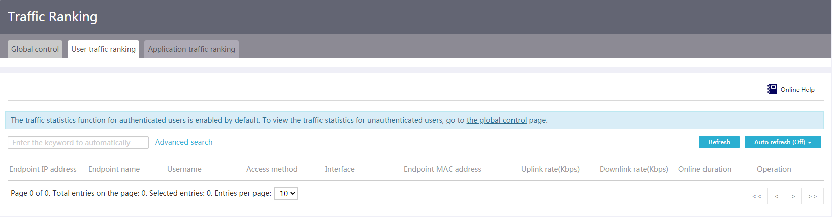
Configure user traffic ranking
Restrictions and guidelines
The user traffic ranking function for authenticated users is always enabled, and does not need your operation. To view the user traffic ranking function for unauthenticated users, you must first enable the user traffic ranking function for the related interfaces on the global control page.
Procedure
1. From the navigation pane, select Network Behaviors > Traffic Ranking.
2. Click the User traffic ranking tab.
3. Click the Rate limit icon in the Operation column for an interface.
4. On the page that opens, select an application interface, and configure the upload bandwidth and download bandwidth.
5. Click Apply to complete the endpoint rate limit configuration.
6. Click the Details icon in the Operation column for an interface to enter the details page showing the user traffic and other information.
Figure 59 User traffic ranking
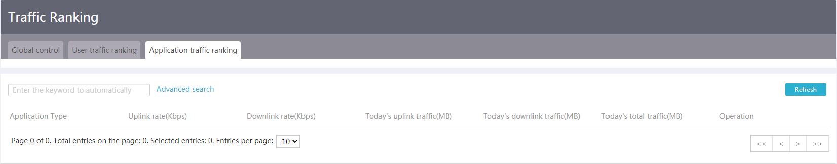
Configure application traffic ranking
Restrictions and guidelines
To configure application traffic ranking, you must first enable application traffic ranking on the global control page.
Procedure
1. From the navigation pane, select Network Behaviors > Traffic Ranking.
2. Click the Application traffic ranking tab.
3. Click the Details icon in the Operation column for an application to enter the details page showing application traffic and other information.
Figure 60 Application traffic ranking
Network security
Firewall
Introduction to the firewall feature
The firewall feature identifies packets based on security rules and takes actions to prevent illegal packets from entering the network.
Restrictions and guidelines
Specify priorities for security rules carefully. Security rules are matched in priority order. Once a matching security rule is found, the firewall takes the action specified by the rule.
Prerequisites
Before configuring security rules, complete the following tasks:
· Configure WAN settings.
· Configure the time ranges to be used for the security rules.
Add a security rule
1. From the navigation pane, select Network Security > Firewall.
Figure 61 Security rules
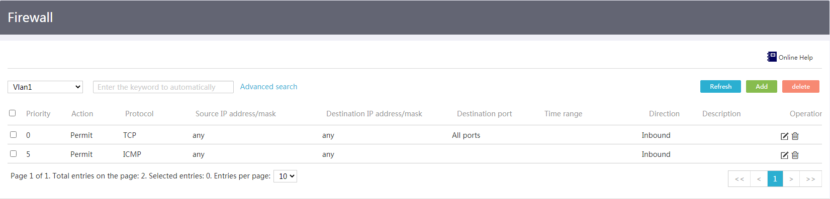
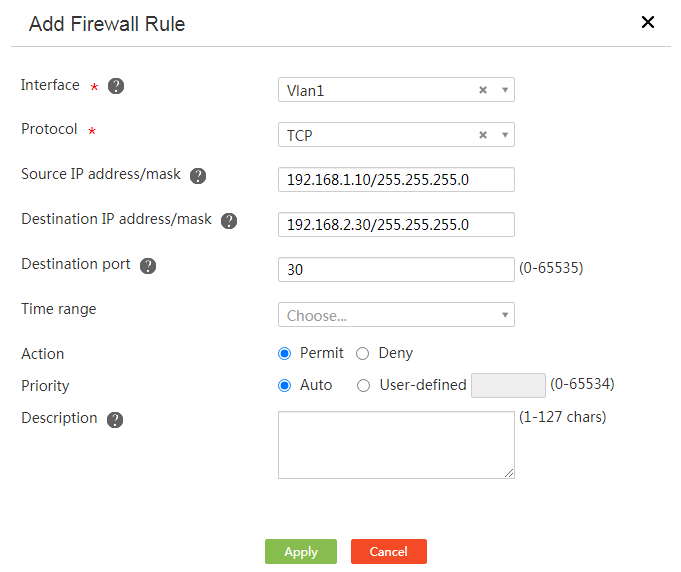
2. Click Add.
3. In the Interface field, select the interface to which you want to apply the security rule. The firewall will use the rule to match packets that arrive at the interface.
4. In the Protocol field, select the protocol that the target packets use.
¡ To match transport layer packets, select TCP or UDP.
¡ To match ping or tracert packets, select ICMP.
¡ To match packets of all protocols, select All protocols.
5. In the Source IP address/mask field, enter the IP address and mask of the packet sender. To match packets from all senders, enter any.
6. In the Destination IP address/mask field, enter the IP address and mask of the intended packet receiver. To match packets destined for all receivers, enter any.
7. In the Destination port field, enter the destination port number of the target packets, for example, 80 for HTTP packets.
8. In the Time range field, select the time range during which you want the rule to take effect.
9. In the Action field, select the action to be taken on target packets.
10. In the Priority field, perform one of the following tasks:
¡ For the system to assign the rule a priority, select Auto. The system assigns priorities to rules according to the rule configuration order. The priority numbering step is 5.
¡ To enter a priority value, select User-defined. A smaller value represents a higher priority.
11. In the Description field, enter a description for the rule.
12. Click Apply.
Figure 62 Adding a security rule
Attack defense
Introduction to attack defense
DDoS attacks are common on the Internet and can cause greater harm than traditional DoS attacks. This feature can protect your devices and network against the following types of attacks:
· Single-packet attacks—An attacker uses malformed packets to paralyze the target system. For example, in a LAND attack, the IP address of the target system is used as both the source IP address and destination IP address of TCP packets. The attacker sends those packets to exhaust connection resources of the target system and make the target system unable to process normal services.
· Abnormal flow attacks—Include the following types of attacks:
¡ Scanning attacks—In order to find a way to intrude into the target network, an attacker scans host addresses and ports to probe the target network topology and open ports.
¡ Flood attacks—An attacker sends a large number of forged requests to the target system. The system is too busy responding to these forged requests to provide services for legitimate users.
The device supports preventing the following DDoS attacks:
· Single-packet attacks—Fraggle attacks, LAND attacks, WinNuke attacks, TCP flag attacks, ICMP unreachable packet attacks, ICMP redirect packet attacks, Smurf attacks, IP source route attacks, IP record route attacks, and large ICMP packet attacks.
· Abnormal flow attacks—Scanning attacks, SYN flood attacks, UDP flood attacks, and ICMP flood attacks.
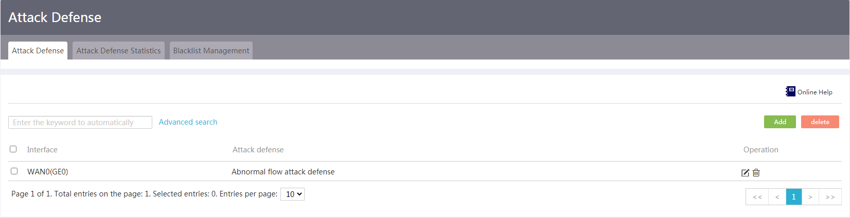
Configure attack defense
1. From the navigation pane, select Network Security > Attack Defense.
2. On the Attack Defense tab, click Add.
Figure 63 Attack defense
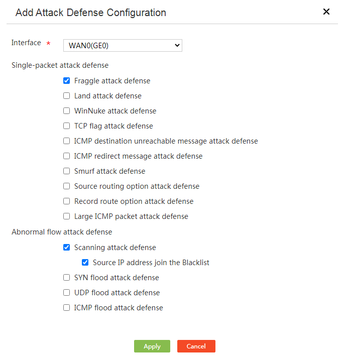
3. On the page that opens, configure attack defense as follows:
¡ From the Interface list, select an interface to which the attack defense configuration applies.
¡ Enable attack defense for single-packet attacks.
As a best practice, enable attack defense for all types of single-packet attacks.
¡ Enable attack defense for abnormal flow attacks.
After enabling scanning attack defense, you can select to add packet source IP addresses to the blacklist. The device drops packets with the matching source IP address. To view IP addresses added to the blacklist, access the Blacklist Management page.
As a best practice, enable flood attack defense based on the network traffic type.
4. Click Apply.
Figure 64 Adding an attack defense configuration entry
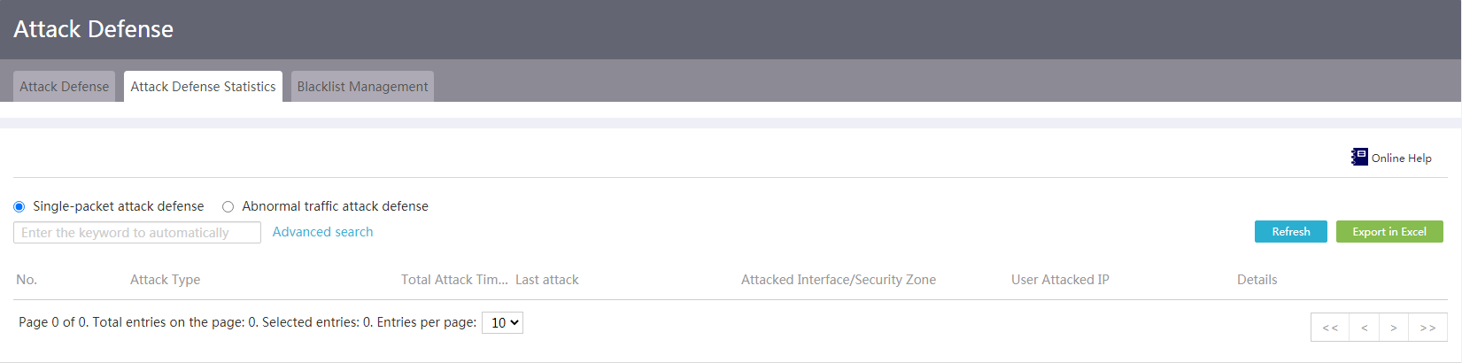
Attack defense statistics
Introduction
Use this feature to view details about DDoS attacks on the device, including the attack type, total attack times, time when the last attack occurred, attacked interface/security zone, and user attacked IP.
Procedure
1. From the navigation pane, select Network Security > Attack Defense.
2. Click the Attack Defense Statistics tab.
3. To view statistics about single-packet attacks, select Single-packet attack defense.
4. To view statistics about abnormal flow attacks, click Abnormal traffic attack defense.
5. To export the statistics, click Export in Excel.
Figure 65 Attack defense statistics
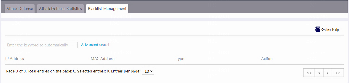
Blacklist management
Introduction
After enabling scanning attack defense, you can add source IP addresses to the blacklist. The device drops packets with the matching source IP address.
To view IP addresses added to the blacklist, navigate to the Blacklist Management page. This page records information about the blacklist, including the IP address added to the blacklist, MAC address, type, and action.
Procedure
1. From the navigation pane, select Network Security > Attack Defense.
2. Click the Blacklist Management tab.
3. To remove an IP address from the blacklist, click the delete icon in the Action column for the IP address.
Figure 66 Blacklist management
Connection limit
Introduction to connection limit
Use connection limit to limit per-IP connections for better resource allocation and attack prevention.
When the number of TCP or UDP connections from an IP address exceeds the connection limit, no connections from the IP address are permitted until the connection count falls below the connection limit.
You can configure the following connection limits:
· Network connection limits—Limit the number of connections from each IP address in an IP address range. This limit method is used to limit the total number of connections received on all interfaces from one IP address.
· VLAN-based network connection limits—Limit the number of connections from each IP address on a VLAN interface. This limit method is used to limit the number of connections received on one VLAN interface from one IP address.
Configure network connection limits
1. From the navigation pane, select Network Security > Connection Limit.
2. On the Connection Limits tab, select Enable Network Connection Limit.
Figure 67 Network connection limit rules
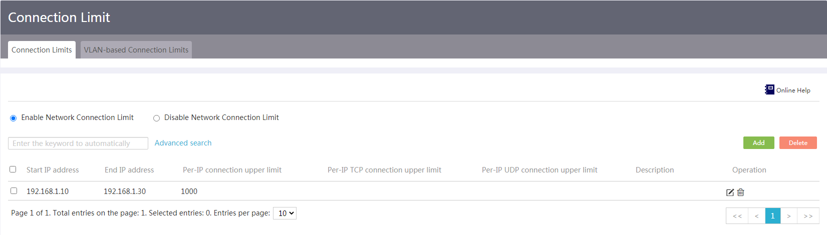
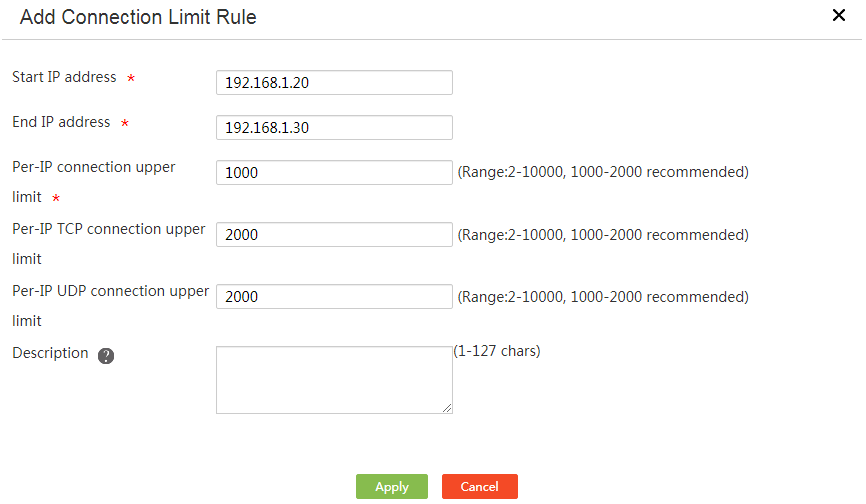
3. Click Add. The Add Connection Limit Rule page opens.
4. Enter a start IP address in the Start IP address field.
5. Enter an end IP address in the End IP address field.
6. Enter the total maximum number of TCP connections and UDP connections sourced from each IP address in the Per-IP connection upper limit field.
Connections with the same source IP address but a different source port number, destination IP address, destination port number, or protocol type are considered as different connections.
7. To limit TCP connections per IP address, enter the maximum number of TCP connections in the Per-IP TCP connection upper limit field.
The maximum number of TCP connections must be smaller than or equal to the total maximum number of TCP connections and UDP connections.
8. To limit UDP connections per IP address, enter the maximum number of UDP connections in the Per-IP UDP connection upper limit field.
The maximum number of UDP connections must be smaller than or equal to the total maximum number of TCP connections and UDP connections.
9. Enter a rule description in the Description field.
10. Click Apply.
Figure 68 Add/edit network connection limit rule
Configure VLAN-based network connection limits
1. From the navigation pane, select Network Security > Connection Limit.
2. Click the VLAN-based Network Connection Limits tab.
Figure 69 VLAN-based network connection limits
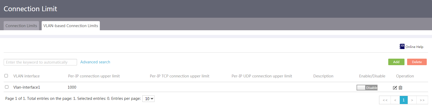
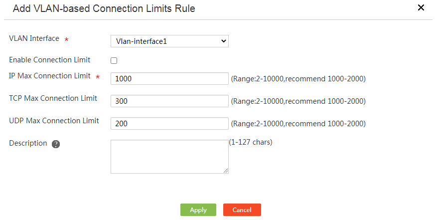
3. Click Add. The Add VLAN-based Connection Limits Rule page opens.
4. Select a VLAN interface from the VLAN Interface list.
5. Select Enable Connection Limit.
6. Enter the total maximum number of TCP and UDP connections sourced from each IP address in the IP Max Connection Limit field.
Connections with the same source IP address but a different source port number, destination IP address, destination port number, or protocol type are considered as different connections.
7. To limit TCP connections per IP address, enter the maximum number of TCP connections in the TCP Max Connection Limit field.
The maximum number of TCP connections must be smaller than or equal to the total maximum number of TCP connections and UDP connections.
8. To limit UDP connections per IP address, enter the maximum number of UDP connections in the UDP Max Connection Limit field.
The maximum number of UDP connections must be smaller than or equal to the total maximum number of TCP connections and UDP connections.
9. Enter a rule description in the Description field.
10. Click Apply.
Figure 70 Add VLAN-based network connection limits rule
MAC address filter
Introduction to MAC address filter
If you want to permit or deny packets sent by specific devices, you can configure MAC address filter on Layer 3 interfaces that connect to the devices.
MAC address filter filters packets that are sourced from specific MAC addresses.
· If whitelist is enabled, the device permits only packets that are sourced from the MAC addresses on the whitelist.
· If blacklist is enabled, the device drops only packets that are sourced from the blacklisted MAC addresses.
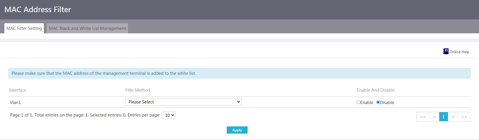
Configure a MAC address filter
Restrictions and guidelines
If you want to enable whitelist MAC address filter on the interface that connects to the management endpoint, make sure the MAC address of the management endpoint has already been added to the whitelist.
Procedure
1. From the navigation pane, select Network Security > MAC Address Filter.
2. Select Whitelist or Blacklist as the filtering method for the interface where you want to enable this feature, and click Enable.
3. Click Apply.
Figure 71 MAC filter settings
Add a whitelist or blacklist entry
Restrictions and guielines
The MAC address whitelist and blacklist configuration steps are similar. The following procedure describes the MAC address whitelist configuration as an example.
Procedure
1. From the navigation pane, select Network Security > MAC Address Filter.
2. Click the MAC Black and White List Management tab.
3. On the White list tab, you can add MAC addresses to the whitelist.
Figure 72 MAC blacklist and whitelist
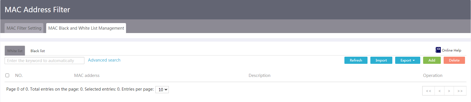
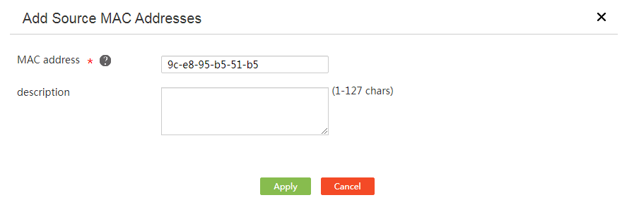
4. Click Add.
5. On the page that opens, enter the MAC address that you want to add to the whitelist.
6. Click Apply.
Figure 73 Add a MAC address to the whitelist
Bulk add whitelist or blacklist entries
Restrictions and guidelines
The MAC address whitelist and blacklist configuration steps are similar. The following procedure describes the MAC address whitelist configuration as an example.
Procedure
1. From the navigation pane, select Network Security > MAC Address Filter.
2. Click the MAC Black and White List Management tab.
3. On the White list tab, you can add MAC addresses to the whitelist.
4. On the top right of whitelist, click Export > Export template.
5. Open the downloaded template, add MAC addresses, and save the file.
6. On the page, click Import.
7. On the page that opens, click Choose File and select the previously edited file.
8. Click Apply.
Edit whitelist or blacklist
Restrictions and guidelines
The MAC address whitelist and blacklist configuration steps are similar. The following procedure describes the MAC address whitelist configuration as an example.
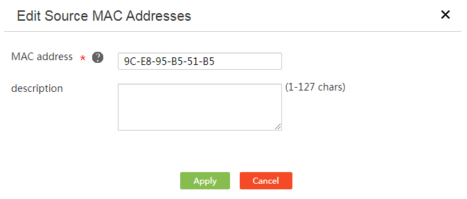
Procedure
1. From the navigation pane, select Network Security > MAC Address Filter.
2. Click the MAC Black and White List Management tab.
3. On the White list tab, you can add MAC addresses to the whitelist.
4. Click the Edit icon for a MAC address entry.
5. On the page that opens, specify a new MAC address, and then click Apply.
Figure 74 Edit source MAC address
ARP attack protection
Introduction to ARP attack protection
ARP attack protection includes the following features:
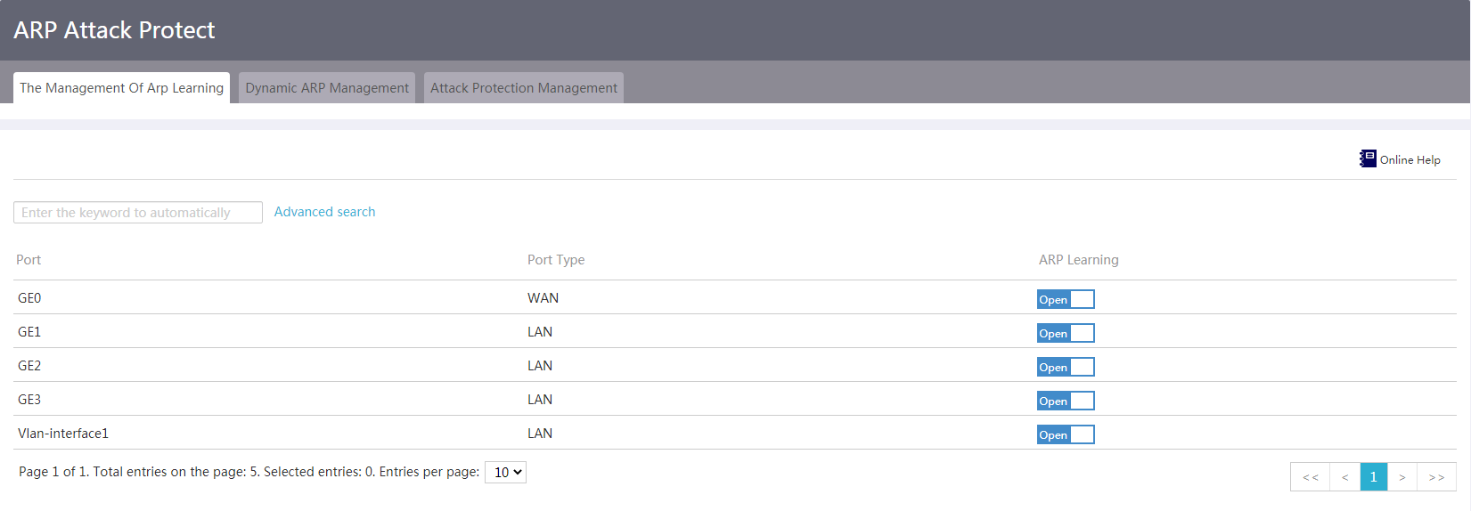
· Dynamic ARP learning—Controls the enabling status of dynamic ARP learning on a per-interface basis. When dynamic ARP learning is disabled on an interface, the interface cannot learn dynamic ARP entries. To improve security, you can disable dynamic ARP learning on an interface if the interface has already learnt ARP entries for all valid hosts.
· Dynamic ARP management—Includes dynamic ARP entry management, ARP scanning, and fixed ARP.
¡ Dynamic ARP entry management—You can refresh, add, or delete dynamic ARP entries.
¡ ARP scanning—This feature creates dynamic ARP entries for valid hosts in the LAN.
¡ Fixed ARP—This feature converts the dynamic ARP entries to static ARP entries.
ARP scanning is typically used together with fixed ARP on a small-scale and stable network. To prevent the device from learning incorrect ARP entries, you can disable dynamic ARP learning after both ARP scanning and fixed ARP are performed.
· Attack protection management—Includes static ARP entry management and control of user access to the external network.
¡ Static ARP entry management—You can refresh, add, delete, batch import, or batch export static ARP entries.
¡ Control of user access to the external network—To prevent illegal internal users from attacking the external network, you can select to allow only users for which the device has static ARP entries to access the external network. Before you configure this setting, first perform ARP scanning and fixed ARP.
Configure dynamic ARP learning
1. From the navigation pane, select Network Security > ARP Attack Protect.
2. On the The Management Of Arp Learning tab, set the enabling status of dynamic ARP learning.
¡ To enable dynamic ARP learning, click Open.
¡ To disable dynamic ARP learning, click Close.
Figure 75 Dynamic ARP learning
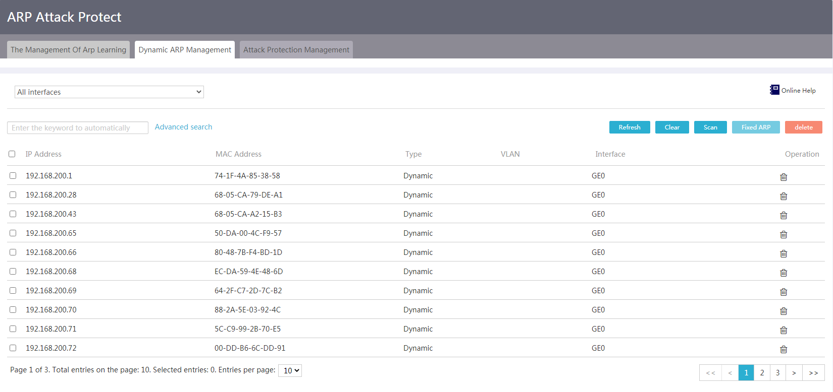
Configure dynamic ARP management
1. From the navigation pane, select Network Security > ARP Attack Protect.
2. Click the Dynamic ARP Management tab.
3. Perform one of the following tasks on existing dynamic AR entries.
¡ To refresh existing ARP entries, click Refresh.
¡ To delete all existing ARP entries, click Clear.
¡ To delete specific dynamic ARP entries, select dynamic ARP entries, click delete, and then click Yes.
Figure 76 Dynamic ARP management
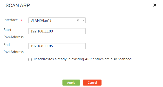
4. Perform ARP scanning and fixed ARP:
a. Click Scan.
b. Select an interface from the Interface list.
c. On the page that opens, enter the start IPv4 address and the end IPv4 address in the Start Ipv4Address and End Ipv4Address fields, respectively. Make sure the IP address range is on the same network segment as the interface.
d. Select IP addresses already in existing ARP entries are also scanned.
e. Select dynamic ARP entries and click Fixed ARP to convert the dynamic ARP entries to static ARP entries.
Figure 77 Scanning
Configure attack protection management
Restrictions and guidelines
Make sure the ARP entry for the host from which you log in to the device is a static ARP entry.
Prerequisites
To add static ARP entries in bulk, you need to save the static ARP entries in a file and then bulk import them from the local file to the device.
To correctly import static ARP entries in bulk, you can first export existing static ARP entries to a file. This file can be used as a template file, in which you can edit static ARP entries as needed.
Procedure
1. From the navigation pane, select Network Security > ARP Attack Protect.
2. Click the Attack Protection Management tab.
3. Control the user access to the external network.
¡ To allow only users for which the device has static ARP entries to access the external network, select Allow only users with static ARP entries to access the external network.
¡ To allow all users to access the external network, select Unlimited access.
4. Perform one of the following tasks on static ARP entries:
¡ To refresh static ARP entries, click Refresh.
¡ To import static ARP entries in bulk, click Import.
¡ To export static ARP entries in bulk, click Export.
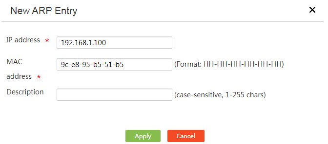
¡ To add a static ARP entry, click Add. On the page that opens, enter the IP address and MAC address for the static ARP entry.
¡ To delete specific static ARP entries, select static ARP entries, click Delete, and then click Yes.
Figure 78 Attack Protection Management
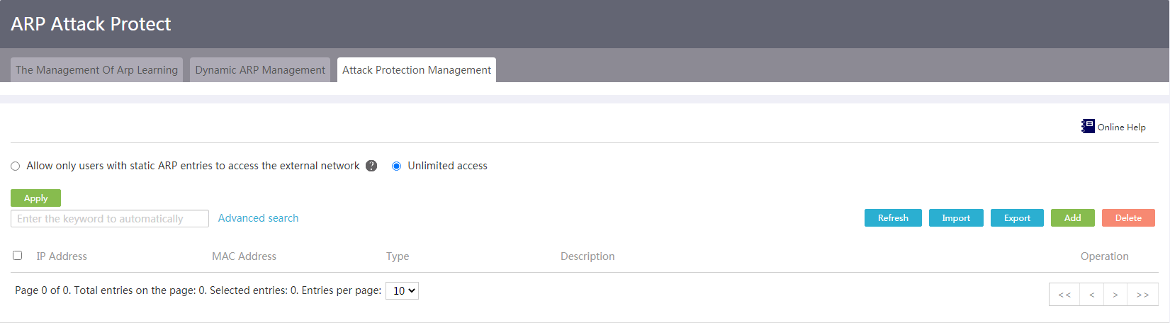
Figure 79 Add an ARP entry
Authentication management
Portal authentication
Introduction to portal authentication
Portal authenticates the identity of users to control user access to networks. The users can access network resources after they pass portal authentication. The device supports the following types of portal authentication:
· Web page authentication—Users initiate portal authentication through a Web browser. The device authenticates a user by the username and password that the user enters on the authentication page.
· WeChat client recognition—Users initiate portal authentication by clicking the network connection link provided by a WeChat official account that the users follow.
Both portal authentication types do not require the installation of authentication client software.
To allow specific users to access specified network resources without portal authentication, you can configure portal-free rules. The matching items for a portal-free rule include the MAC address, IP address, or host name of a user.
Configure the authentication page for Web page authentication
Prerequisites
Configure an IP address for the interface connected to portal users.
Save the image to be used as the background image on the portal authentication page as a local file named background-logon.jpg on the client through which you log in to the device. Make sure the resolution of the image is 1440 × 900 and the size is 255 K.
Procedure
1. From the navigation pane, select Authentication > Portal Authentication.
2. Select Web page authentication.
3. Select Enabling Web authentication service. To configure portal authentication, you must enable the Web authentication service.
¡ Set the session timeout time in the Session timeout field. The device logs out a user if the online duration of the user exceeds the value.
¡ Select an interface to be enabled with portal authentication from the Authentication service interface list. The selected interface must be configured with an IP address.
¡ Select a language in the Language of Authentication page field. Options include English and Chinese. In this example, English is used.
4. Determine whether to allow password change. To allow portal users to change their login passwords, select the Allow password change option.
5. Enter the window title in the Window title field. For example, Welcome to Portal Authentication Page.
6. Enter the window prompt information in the Window prompt information field. For example, xxx company.
7. Click Choose File next to the Import background images field and then select the image file to be used as the background image on the authentication page.
8. Click Submit.
9. Click Preview. The configured authentication page is displayed.
Figure 80 Web page authentication settings
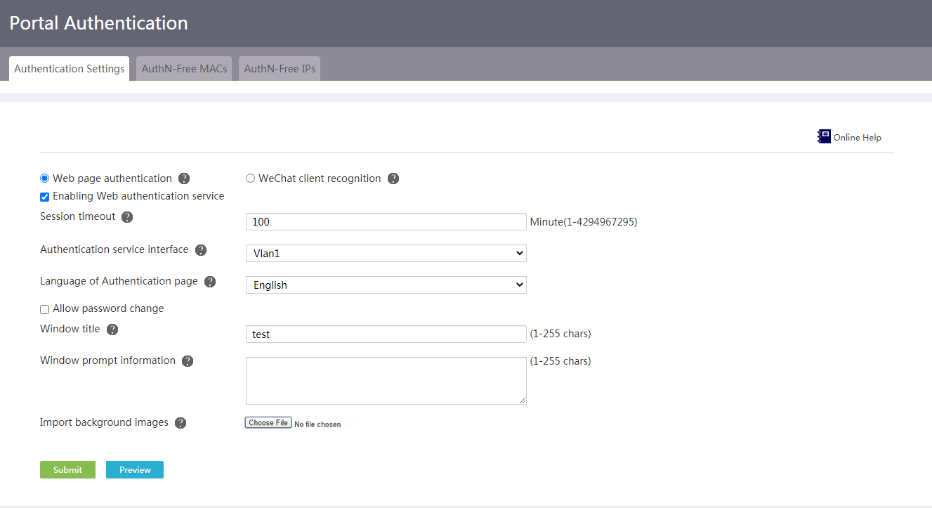
Configure the authentication page for WeChat client recognition
Prerequisites
Configure an IP address for the interface connected to portal users.
Save the image to be used as the background image on the portal authentication page as a local file named guanzhu.jpg on the client through which you log in to the device. Make sure the resolution of the image is 422 × 251 and the size is 47 K.
Procedure
1. From the navigation pane, select Authentication > Portal Authentication.
2. Select WeChat client recognition.
3. Select Enabling Web authentication service. To configure portal authentication, you must enable the Web authentication service.
¡ Set the session timeout time in the Session timeout field. The device logs out a user if the online duration of the user exceeds the value.
¡ Select an interface to be enabled with portal authentication from the Authentication service interface list. The selected interface must be configured with an IP address.
4. Enter the window title in the Window title field. For example, Welcome to Portal Authentication Page.
5. Enter the window prompt information in the Window prompt information field. For example, xxx company.
6. Click Choose File next to the Import background images field and then select the image file to be used as the background image on the authentication page.
7. In the WeChat DNS field, enter the domain name of the device set in the WeChat official account. The domain name of the device can contain only letters, digits, hyphens (-), underscores (_), and dots (.). Additionally, the domain name cannot start with a dot (.).
8. Click Submit.
9. Click Preview. The configured authentication page is displayed.
Figure 81 WeChat client recognition settings
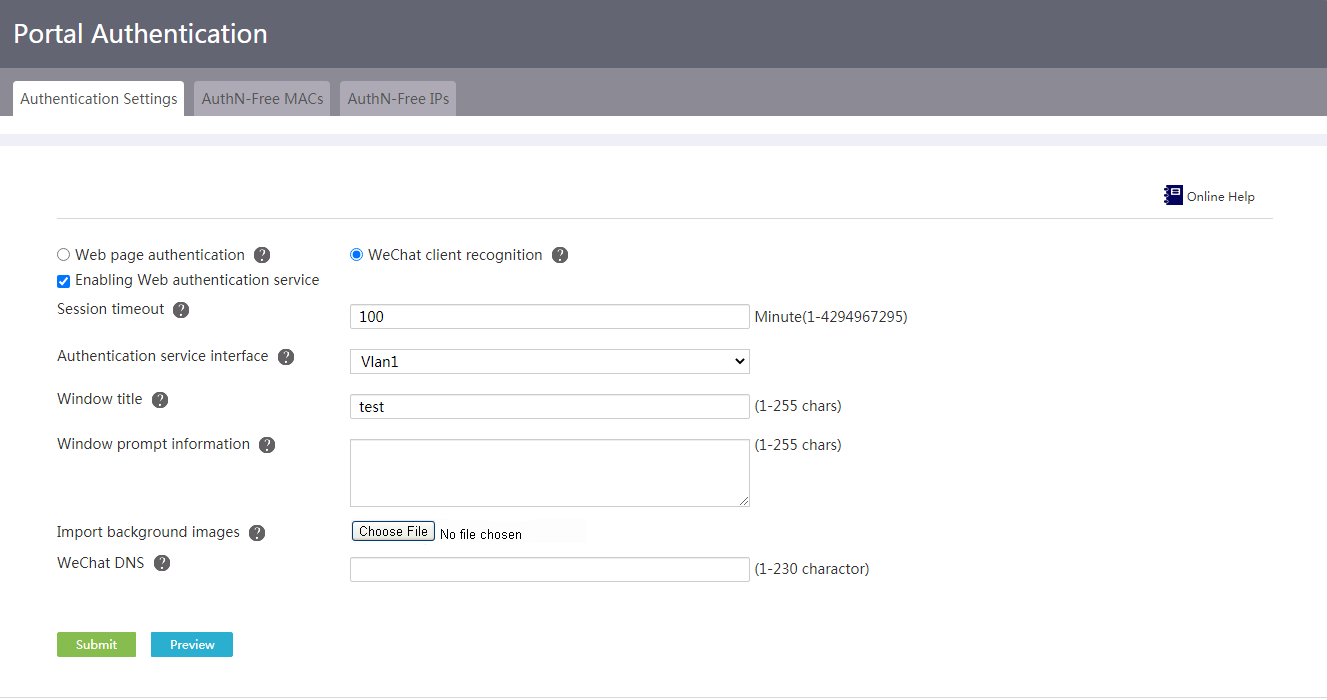
Add an authentication-free MAC address
1. From the navigation pane, select Authentication > Portal Authentication.
2. Click the AuthN-Free MACs tab.
Figure 82 Authentication-free MAC address configuration page
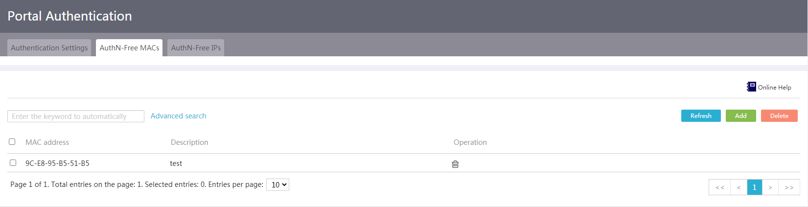
3. Click Add.
4. On the page that opens, enter a MAC address in the MAC address field.
5. Enter a description for the authentication-free MAC address in the Description field.
6. Click Apply.
Figure 83 Add an authentication-free MAC address
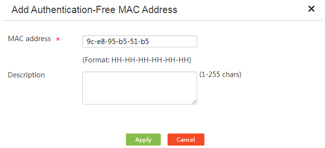
Add an authentication-free IP address or host name
1. From the navigation pane, select Authentication > Portal Authentication.
2. Click the AuthN-Free IPs tab.
Figure 84 Authentication-free IP address or host name configuration page
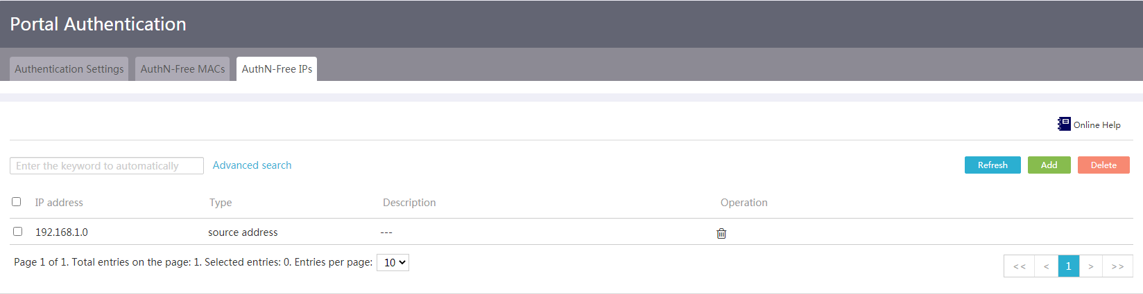
3. Click Add.
4. On the page that opens, select an address type from the Address add mode list. Supported options include Source address, Destination address, and Hostname.
¡ If you select Source address or Destination address, enter an IP address and mask in the IP Address field.
¡ If you select Hostname, enter the host name in the Hostname field.
5. Enter a description for the authentication-free IP address or host name in the Description field.
6. Click Apply.
Figure 85 Add an authentication-free IP address
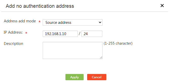
PPPoE server
About this task
To provide the PPPoE broadband dialup service that can allocate IP addresses and perform authentication for dialup users, configure the PPPoE server.
Restrictions and guidelines
After you complete the configuration in this section, the device acts as the PPPoE server to allocate IP addresses and perform authentication for dialup users. To provide the Internet access service for dialup users, you must configure the WAN settings in addition to the PPPoE server settings. To configure the WAN settings, access the Fast Configuration or Network > WAN Settings page.
Procedure
1. From the navigation pane, select Authentication > PPPoE Server.
Figure 86 PPPoE server
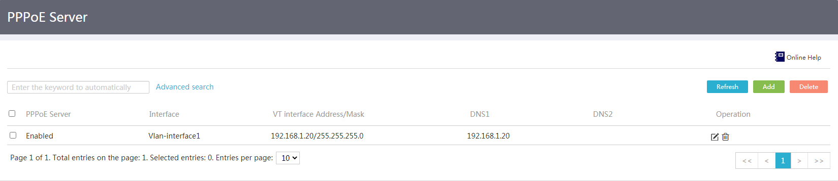
2. Click Add. The page for adding a PPPoE server opens.
3. In the Apply to field, select a device interface used for providing the PPPoE dialup service.
4. In the VT interface address field, enter the VT interface IP address to enable the PPPoE server to allocate IP addresses.
5. In the Subnet Mask field, enter the subnet mask for the VT interface IP address.
6. In the User address pool field, enter the IP addresses to be allocated to PPPoE dialup users.
7. In the DNS1 field, enter the IPv4 address of the primary DNS server for PPPoE dialup users.
8. In the DNS2 field, specify the IPv4 address for the secondary DNS server for PPPoE dialup users.
9. In the Max. endpoints allowed on the server field, enter the maximum number of users that are allowed to dial up for Internet access.
10. Click Apply to enable the PPPoE service.
Figure 87 Adding a PPPoE server
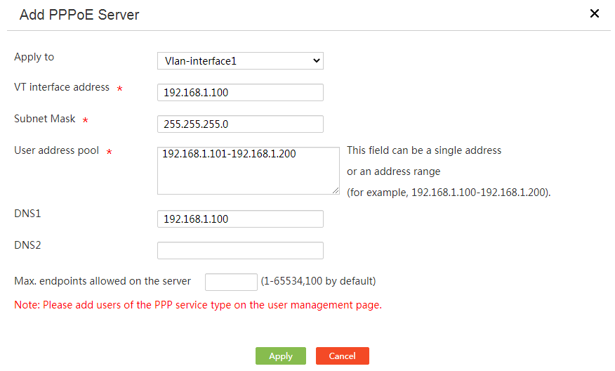
User management
About this task
Use user management to manage user accounts for users that access the external network through the device. The user account information includes user credentials (the username and password) and network service information (including the available services and validity period). During identity authentication (such as portal authentication and PPPoE authentication), the device will use user account information to authenticate users. Only users of which the user account information matches that in the user management module can pass identity authentication to access the external network.
Add a user account
Prerequisites
To bind this user account to a specific host by user account-MAC binding, you must first obtain the MAC address of the NIC on the host.
Procedure
1. From the navigation pane, select Authentication > User Management.
2. On the User Settings tab, click Add.
Figure 88 User settings
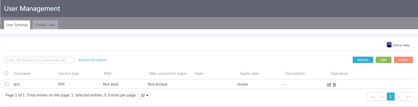
3. In the dialog box that opens, enter a username in the Username field.
4. In the State field, set the status of the user account.
¡ To allow the users that use this account to request network services, select Active.
¡ To prevent users from using this account to request network services, select Blocked. Select this status if you temporarily do not want this user account to take effect.
5. In the Password field, enter a password.
If you do not configure a password, no password is required by the system for user identity authentication. As a best practice to enhance security, configure a password for the user account.
6. In the Service type field, select services for the user account.
7. In the MAC field, select whether to bind the user account to a MAC address.
¡ To bind the user account to a MAC address, select Bind and enter a MAC address in the format of xx-xx-xx-xx-xx-xx.
During authentication, the device will match the specified MAC address with the actual MAC address of the user that uses this account. The user fails authentication if the two MAC addresses do not match.
¡ To not bind the user account to a MAC address, select Not bind.
Users can use this user account to access the external network through this device from any endpoint.
8. In the Max concurrent logins field, set the maximum number of concurrent users that can use this account
If you do not set a limit, the device does not limit the number of concurrent users that use this account.
9. In the ExpireDate field, configure a validity period for the user account.
Users that use this user account can pass authentication only within the validity period.
10. In the Description field, configure a description for the user account.
For easy to remember and manage user accounts, configure a description for each user account.
11. Click Apply.
Figure 89 Adding a user
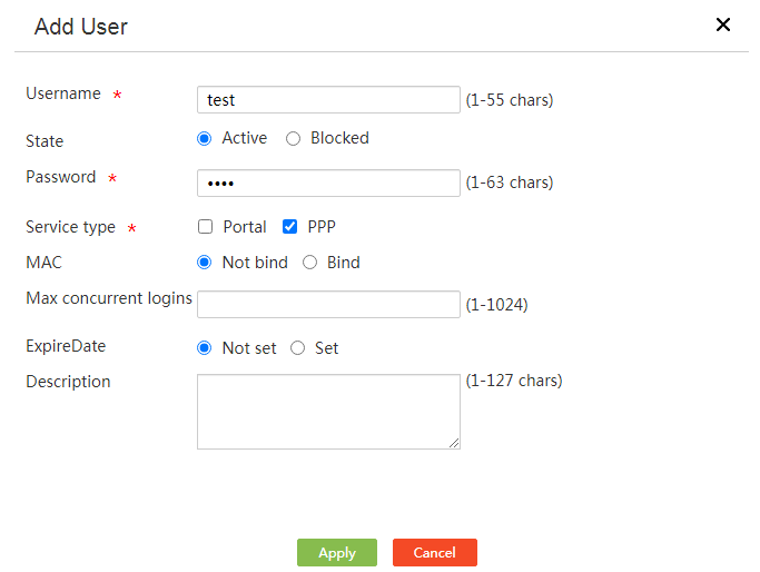
Delete a user account
Restrictions and guidelines
Deleting of a user account will not log out online users that use this account. The deletion operation only forbids new users to use this account to come online.
Procedure
1. From the navigation pane, select Authentication > User Management.
2. Click the Delete icon in the Operation column for a user account.
3. In the dialog box that opens, click Yes.
Figure 90 Deleting a user

View online users
Procedure
1. From the navigation pane, select Authentication > User Management.
2. On the Online User tab, you can view online users.
3. Click Advanced search. In the dialog box that opens, configure the filter criteria, and then click Search.
Figure 91 Advanced search
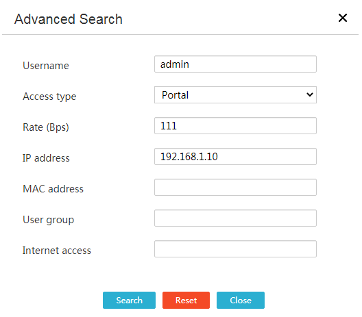
Virtual network
IPsec VPN
Introduction to IPsec VPN
IPsec VPN is a virtual private network established by using the IPsec technology. IPsec transmits data in a secure channel established between two endpoints. Such a secure channel is usually called an IPsec tunnel.
IPsec is a security framework that has the following protocols and algorithms:
· Authentication Header (AH).
· Encapsulating Security Payload (ESP).
· Internet Key Exchange (IKE).
· Algorithms for authentication and encryption.
AH and ESP are security protocols that provide security services. IKE performs automatic key exchange.
The device supports the following networking modes:
· Center-branch mode—Each branch gateway of an enterprise establishes an IPsec tunnel to the gateway of the enterprise center. Branches can securely communicate with the enterprise center through IPsec.
· Branch-branch mode—A branch gateway establishes an IPsec tunnel to another branch gateway of the enterprise. Data communications between branches are protected by IPsec.
Configure the device as a branch node
About this task
In a center-branch network, a branch node needs to establish an IPsec tunnel with the center node.
In a branch-branch network, a branch node needs to establish an IPsec tunnel with another branch node.
Configure basic IPsec settings
1. From the navigation pane, select Virtual Network > IPsec VPN.
2. Click the IPsec policy tab.
Figure 92 IPsec policy configuration page
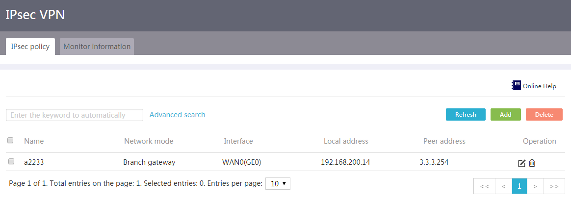
3. Click Add.
4. Enter an IPsec policy name in the Name field.
5. From the Interface field, select an interface to which the IPsec policy applies.
Make sure the selected interface can reach the peer.
6. Select the Branch gateway mode.
7. Enter the remote IP address of the IPsec tunnel in the Peer gateway address field.
The IP address is often the WAN interface address of the headquarters gateway or branch gateway.
8. Use the default and only authentication method Preshared key.
9. Enter the preshared key used with the peer in the Preshared key field.
The preshared key is negotiated and advertised in advance.
10. In the IPsec protected flows area, configure the following settings:
a. Select a protocol to be protected by the IPsec tunnel from the Protocol list.
b. Enter the local protected IP address/mask in the Local subnet/mask field.
c. Enter the local protected port in the Local port field.
This field is configurable only when the protected protocol is TCP or UDP.
The device performs IPsec encapsulation for packets sent by the source protected port and IP address.
d. Enter the peer protected IP address/mask in the Peer subnet/mask field.er
e. Enter the peer protected port in the Peer port field.
This field is configurable only when the protected protocol is TCP or UDP.
The device decapsulates only the IPsec packets received from the destination protected port and IP address.
f. Click the Add icon.
g. Repeat the previous steps to add more IPsec protected flow entries.
Figure 93 Add an IPsec policy
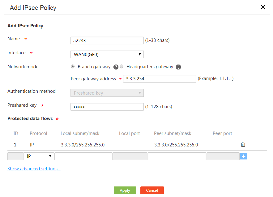
Configure IKE settings
Perform this task to change the default IKE settings.
1. Click the Show advanced settings link on the Add IPsec Policy page.
2. On the IKE settings tab, select a negotiation mode. Options include Main mode and Aggressive mode.
The aggressive mode is faster than the main mode but it does not provide identity information protection. The main mode provides identity information protection but is slower. Choose the appropriate negotiation mode according to your requirements.
If the device's public IP address is dynamically assigned, select the aggressive mode as a best practice.
3. Select an ID type and enter the local ID in the Local ID field for the IKE authentication. ID types include IP address, FQDN, and User-FQDN.
Make sure the ID type and the local ID are the same as the remote ID configuration for the peer.
If the IKE negotiation mode is the main mode, you must select IP address.
4. Select an ID type and enter the remote ID in the Remote ID field for the IKE authentication. ID types include IP address, FQDN, and User-FQDN.
Make sure the ID type and the remote ID are the same as the local ID configuration for the peer.
5. Select whether to enable DPD. DPD detects dead peers and the device will delete the IPsec tunnels established with dead peers.
As a best practice, enable DPD for the device to quickly detect availability problems of IPsec tunnels.
6. Select Recommended to use the recommended algorithm combination, or select Customize to customize the combination of encryption, authentication, and PFS algorithms for IKE negotiation process.
Make sure two peers of an IPsec tunnel are configured with the same encryption, authentication, and PFS algorithms.
7. Enter the IKE SA lifetime in the SA lifetime field. After the lifetime expires, the IKE parameters will be renegotiated.
Figure 94 Configure advanced IKE settings
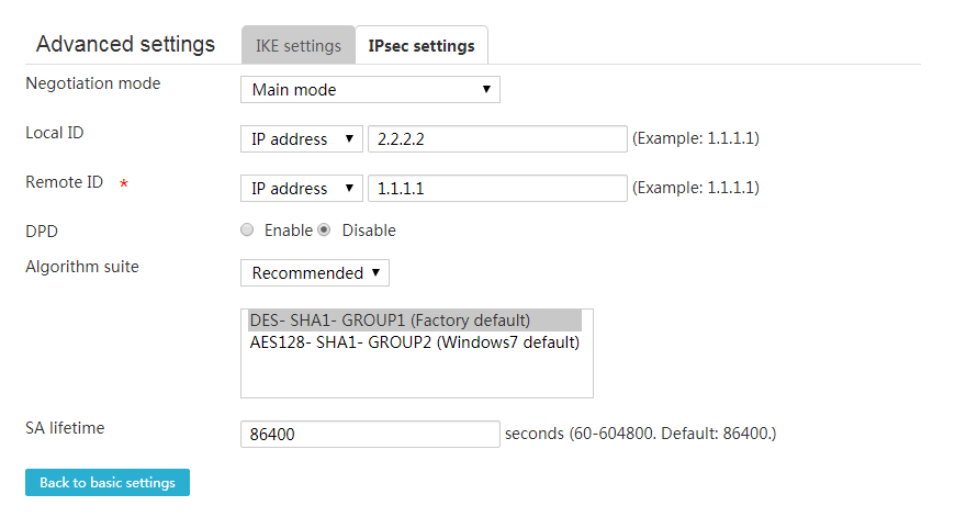
Configure advanced IPsec settings
Perform this task to change the default advanced IPsec settings
1. Configure basic IPsec settings, and then click Show advanced settings link.
2. On the page that opens, click the IPsec settings tab.
3. Select Recommended to use the recommended security protocols, encryption algorithms, and authentication algorithms, or select Customize to customize security protocols, authentication algorithms, encryption algorithms, encapsulation modes, and PFS algorithms.
If both the local IPsec-protected network segment and the peer protected network segment belong to private networks, select the tunnel encapsulation mode as a best practice.
Make sure two peers of an IPsec tunnel are configured with the same security protocol, authentication algorithms, encryption algorithms, encapsulation mode, and PFS algorithm.
4. Enter an interval that triggers IPsec renegotiation in the Time-based SA lifetime field. If the interval expires, the IPsec parameters will be renegotiated.
5. Enter the amount of the traffic that triggers IPsec renegotiation in the Traffic-based SA lifetime field. If the traffic exceeds the configured traffic limit, the IPsec parameters will be renegotiated.
6. Select an IPsec SA negotiation triggering mode in the Trigger mode field. Options include Flow trigger and Long connection trigger.
¡ Flow trigger—Triggers IPsec SA negotiation when the traffic to be sent meets the IPsec protection requirements.
¡ Long connection trigger—Triggers IPsec SA negotiation when required IPsec configuration is complete.
7. Click Back to basic settings to go back to the Add IPsec Policy page.
8. Click Apply.
Figure 95 Configure advanced IPsec settings
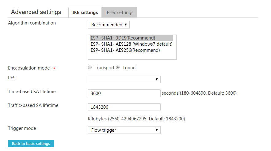
Configure the device as a center node
About this task
In a center-branch network, the center node needs to establish an IPsec tunnel with a branch node.
Configure basic IPsec settings
1. From the navigation pane, select Virtual Network > IPsec VPN.
2. Click the IPsec policy tab.
Figure 96 IPsec policy configuration page
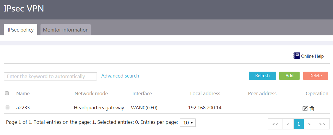
3. Click Add.
4. Enter an IPsec policy name in the Name field.
5. From the Interface field, select an interface to which the IPsec policy applies.
Make sure the selected interface can reach the branch.
6. Select the Headquarters gateway mode.
7. Use the Preshared key authentication method.
The device supports only the preshared key authentication method.
8. Enter the preshared key used with the peer in the Preshared key field.
The preshared key is negotiated and advertised in advance.
Figure 97 Add an IPsec policy
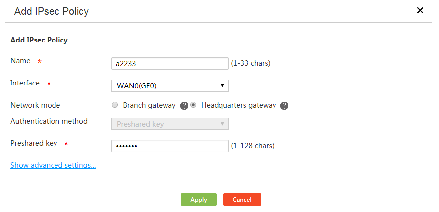
Configure IKE settings
Perform this task to change the default IKE settings.
1. Click the Show advanced settings link on the Add IPsec Policy page.
2. On the IKE settings tab, select a negotiation mode. Options include Main mode and Aggressive mode.
The aggressive mode is faster than the main mode but it does not provide identity information protection. The main mode provides identity information protection but is slower. Choose the appropriate negotiation mode according to your requirements.
If the device's public IP address is dynamically assigned, select the aggressive mode as a best practice.
3. Select an ID type and enter the local ID in the Local ID field for the IKE authentication. ID types include IP address, FQDN, and User-FQDN.
Make sure the ID type and the local ID are the same as the remote ID type and remote ID configured on the branches.
If the IKE negotiation mode is the main mode, you must select IP address.
4. Select whether to enable DPD. DPD detects dead peers and the device will delete the IPsec tunnels with dead peers.
As a best practice, enabling DPD for the device to obtain the availability of IPsec tunnels in time.
5. Select Recommended to use the recommended algorithm combination, or select Customize to customize the combination of encryption, authentication, and PFS algorithms for IKE negotiation process.
Make sure two peers of an IPsec tunnel are configured with the same encryption, authentication, and PFS algorithms.
6. Enter the IKE SA lifetime in the SA lifetime field. After the lifetime expires, the IKE parameters will be renegotiated.
Figure 98 Configure advanced IKE settings
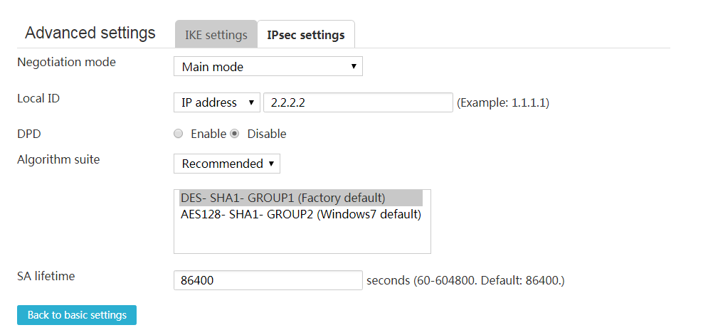
Configure advanced IPsec settings
Perform this task to change the default advanced IPsec settings
1. Configure basic IPsec settings, and then click Show advanced settings link.
2. On the page that opens, click the IPsec settings tab.
3. Select Recommended to use the recommended security protocols, encryption algorithms, and authentication algorithms, or select Customize to customize security protocols, authentication algorithms, encryption algorithms, encapsulation modes, and PFS algorithms.
If both the local IPsec-protected network segment and the peer protected network segment belong to private networks, select the tunnel encapsulation mode as a best practice.
Make sure two peers of an IPsec tunnel are configured with the same security protocol, authentication algorithms, encryption algorithms, encapsulation mode, and PFS algorithm.
4. Enter an interval that triggers IPsec renegotiation in the Time-based SA lifetime field. If the interval expires, the IPsec parameters will be renegotiated.
5. Enter the amount of the traffic that triggers IPsec renegotiation in the Traffic-based SA lifetime field. If the traffic exceeds the configured traffic limit, the IPsec parameters will be renegotiated.
6. Click Back to basic settings to go back to the Add IPsec Policy page.
7. Click Apply.
Figure 99 Configure advanced IPsec settings
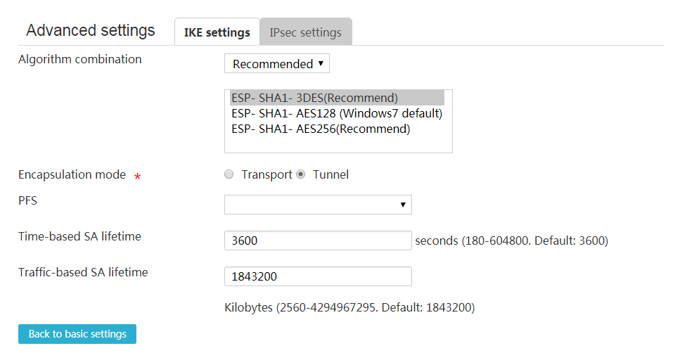
Monitor information
1. From the navigation pane, select Virtual Network > IPsec VPN.
2. Click the Monitor information tab.
Figure 100 Monitor information
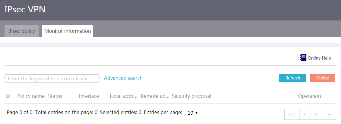
L2TP server
Introduction to L2TP servers
Perform this task to configure basic L2TP server parameters and enable L2TP.
To provide a secure, cost-effective solution for remote users (such as branches and travelers) of an enterprise to access resources in the internal network of the enterprise, configure an L2TP server.
An L2TP server is a device that can process PPP and L2TP protocol packets. Typically, an L2TP server is deployed on the border of the internal network of an enterprise.
Configure an L2TP server
Procedure
1. From the navigation pane, select Virtual Network > L2TP Server.
2. Click the L2TP Config tab.
3. Select enable for the L2TP Server field.
Figure 101 L2TP server configuration
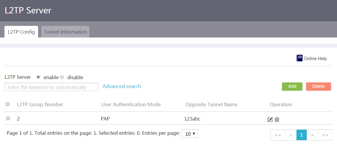
4. Click Add.
5. In the L2TP configuration area, configure L2TP tunnel parameters as follows:
¡ Select the Tunnel peer name option as needed. If you select this option, enter the tunnel name of the L2TP client.
¡ In the Local tunnel name field, enter the tunnel name for the L2TP server.
¡ For the Tunnel authentication parameter, select Enable or Disable as needed.
- If you select Enable, enter the tunnel password in the Tunnel password field. The tunnel authentication feature enhances security. To use this feature, you must enable tunnel authentication on both the L2TP server and L2TP client and make sure their passwords are the same.
- If you select Disable, authentication will not be performed for establishing a tunnel between the L2TP server and L2TP client.
6. From the PPP authentication method list, select None, PAP, or CHAP as needed.
¡ If you select None, authentication will not be performed on users. Use this authentication method with caution because it is of the lowest security.
¡ If you select PAP, a two-way handshake authentication will be performed on users. This authentication method is of medium security.
¡ If you select CHAP, a three-way handshake authentication will be performed on users. This authentication method is of the highest security.
7. In the PPP address configuration area, configure PPP address parameters:
¡ In the VT interface address field, enter the VT interface IP address to enable the L2TP server to allocate IP addresses to L2TP clients or users.
¡ In the VT interface Mask field, enter the subnet mask for the VT interface IP address.
¡ In the User address pool field, enter the IP addresses to be allocated to L2TP clients or users.
8. In the LNS user management area, add PPP users as prompted.
9. Click Display advanced configuration to display the advanced configuration area.
10. In the Advanced configuration area, configure advanced parameters as follows:
¡ In the Hello interval field, enter the Hello interval.
¡ For the AVP hidden field, select Enable or Disable as needed.
- If you select Enable, the tunnel password is used to transfer the AVP data (including tunnel negotiation parameters, session negotiation parameters, and user authentication information) in hidden mode. This feature enhances the data transmission security.
- If you select Disable, AVP data will not be transferred in hidden mode.
¡ For the Flow control field, select Enable or Disable as needed.
- If you select Enable, when L2TP data packets are transmitted and received, the sequence numbers carried in packets are used to identify whether packets are lost and reorder packets. This feature improves the correctness and reliability of L2TP data packet transmission. For this feature to take effect, enable flow control on either of the L2TP server and L2TP client.
- If you select Disable, packets will not be detected or reordered.
¡ For the Mandatory CHAP authentication field, select Enable or Disable as needed.
- If you select Enable, the L2TP server will use CHAP to perform authentication again for a user after the L2TP client authenticates the user. This feature enhances the security. To enable mandatory CHAP authentication, make sure the PPP authentication method is set to CHAP.
- If you select Disable, the L2TP server will not perform mandatory CHAP authentication for users. For users that do not support second CHAP authentication, disable this feature as a best practice.
¡ For the Mandatory LCP renegotiation field, select Enable or Disable as needed.
- If you select Enable, the L2TP server will use LCP renegotiation to perform LCP negotiation and authentication again for a user after the L2TP client authenticates the user. This feature enhances the security. If you enable both mandatory LCP renegotiation and mandatory CHAP authentication, only mandatory LCP renegotiation takes effect.
- If you select Disable, the L2TP server will not perform mandatory LCP renegotiation for users. For users that do not support LCP negotiation, disable this feature as a best practice.
11. Click Apply.
Figure 102 Creating an L2TP group
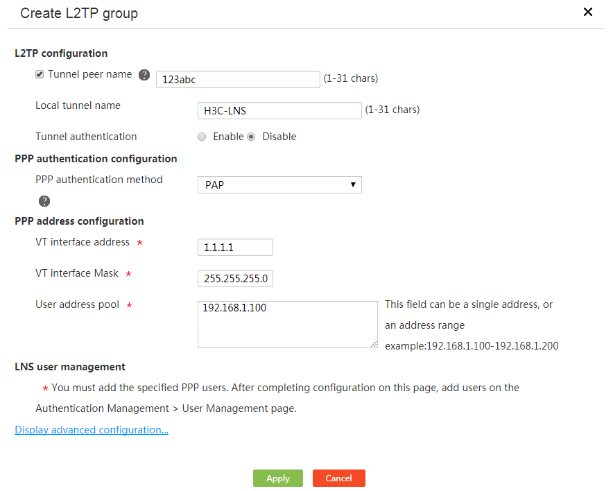
Edit an L2TP group
Procedure
1. From the navigation pane, select Virtual Network > L2TP Server.
2. Click the L2TP Config tab.
3. Click Edit for an L2TP group.
4. Edit the parameters as needed, and then click Apply.
Figure 103 Editing an L2TP group
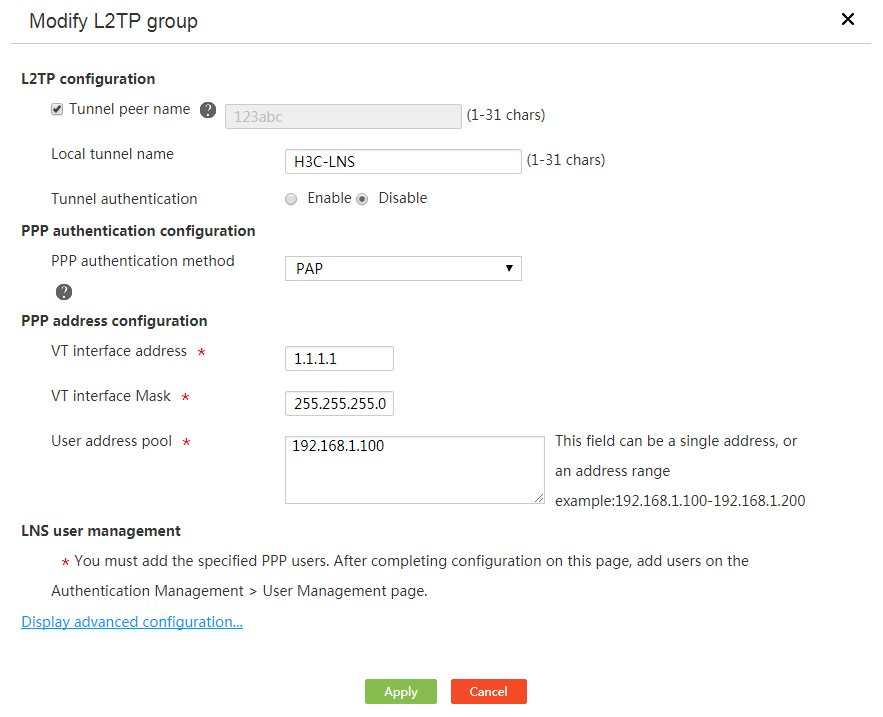
Delete L2TP groups
Procedure
1. From the navigation pane, select Virtual Network > L2TP Server.
2. Click the L2TP Config tab.
3. Perform one of the following tasks:
¡ Click Delete for an L2TP group.
¡ Select multiple L2TP groups, and then click Delete.
4. Click Yes.
Figure 104 Confirming the deletion

View L2TP tunnels
Procedure
1. From the navigation pane, select Virtual Network > L2TP Server.
2. Click the Tunnel Information tab.
Figure 105 L2TP tunnels
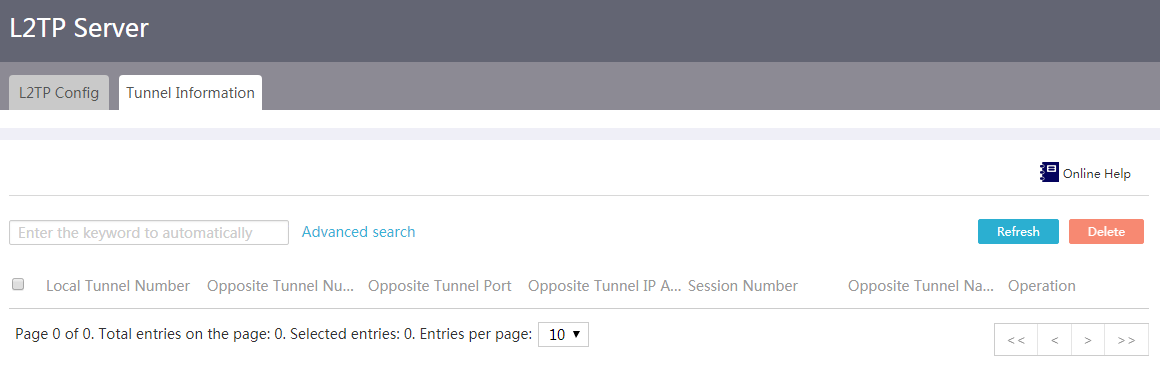
Delete L2TP tunnels
Procedure
1. From the navigation pane, select Virtual Network > L2TP Server.
2. Click the Tunnel Information tab.
3. Perform one of the following tasks:
¡ Click Delete for an L2TP tunnel.
¡ Select multiple L2TP tunnels, and then click Delete.
4. Click Yes.
Figure 106 Confirming the deletion

L2TP client
Introduction to L2TP clients
Perform this task to configure basic L2TP client parameters and enable L2TP.
To provide a secure, cost-effective solution for branches of an enterprise to access resources in the internal network of the enterprise, configure an L2TP server.
An L2TP client is a device that can process PPP and L2TP protocol packets. Typically, an L2TP client is deployed on the egress of an enterprise branch.
Configure an L2TP client
Procedure
1. From the navigation pane, select Virtual Network > L2TP Client.
2. Click the L2TP Config tab.
3. Select enable for the L2TP Client field to enable L2TP.
Figure 107 L2TP client configuration
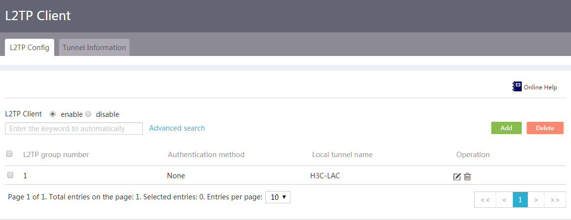
4. Click Add.
5. In the L2TP configuration area, configure L2TP tunnel parameters as follows:
¡ In the Local tunnel name field, enter the tunnel name for the L2TP client.
¡ For the Address assignment method field, select Static or Dynamic as needed.
- If you select Static, you must manually configure an IP address for the virtual PPP interface in the Static IP address field.
- If you select Dynamic, the LNS dynamically allocates an IP address to the virtual PPP interface.
¡ For the Tunnel authentication parameter, select Enable or Disable as needed.
- If you select Enable, enter the authentication password in the Tunnel password field. The tunnel authentication feature enhances security. To use this feature, you must enable tunnel authentication on both the L2TP server and L2TP client and make sure their passwords are the same.
- If you select Disable, authentication will not be performed for establishing a tunnel between the L2TP server and L2TP client.
6. From the PPP authentication method list, select None, PAP, or CHAP as needed.
¡ If you select None, authentication will not be performed on users. Use this authentication method with caution because it is of the lowest security.
¡ If you select PAP, a two-way handshake authentication will be performed on users. This authentication method is of medium security.
¡ If you select CHAP, a three-way handshake authentication will be performed on users. This authentication method is of the highest security.
7. In the L2TP server address field in the L2TP server configuration area, enter the IP address of the L2TP server.
8. In the Advanced configuration area, configure advanced parameters as follows:
¡ In the Hello interval field, enter the Hello interval.
¡ For the AVP hidden field, select Enable or Disable as needed.
- If you select Enable, the tunnel authentication password is used to transfer the AVP data (including tunnel negotiation parameters, session negotiation parameters, and user authentication information) in hidden mode. This feature enhances the data transmission security.
- If you select Disable, AVP data will not be transferred in hidden mode.
¡ For the Flow control field, select Enable or Disable as needed.
- If you select Enable, when L2TP data packets are transmitted and received, the sequence numbers carried in packets are used to identify whether packets are lost and reorder packets. This feature improves the correctness and reliability of L2TP data packet transmission. For this feature to take effect, enable flow control on either of the L2TP server and L2TP client.
- If you select Disable, packets will not be detected or reordered.
9. Click Apply.
Figure 108 Creating an L2TP group
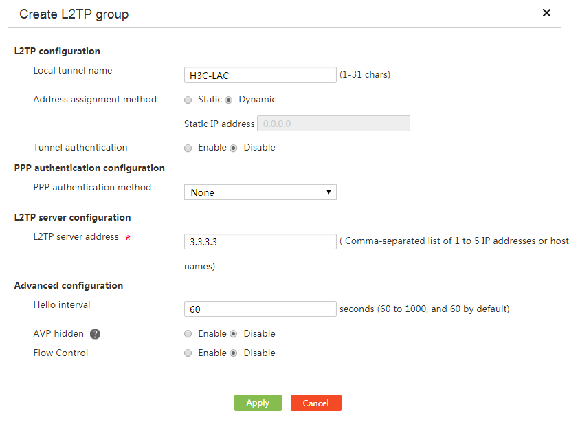
Edit an L2TP group
Procedure
1. From the navigation pane, select Virtual Network > L2TP Client.
2. Click the L2TP Config tab.
3. Click Edit for an L2TP group.
4. Edit the parameters as needed, and then click Apply.
Figure 109 Editing an L2TP group
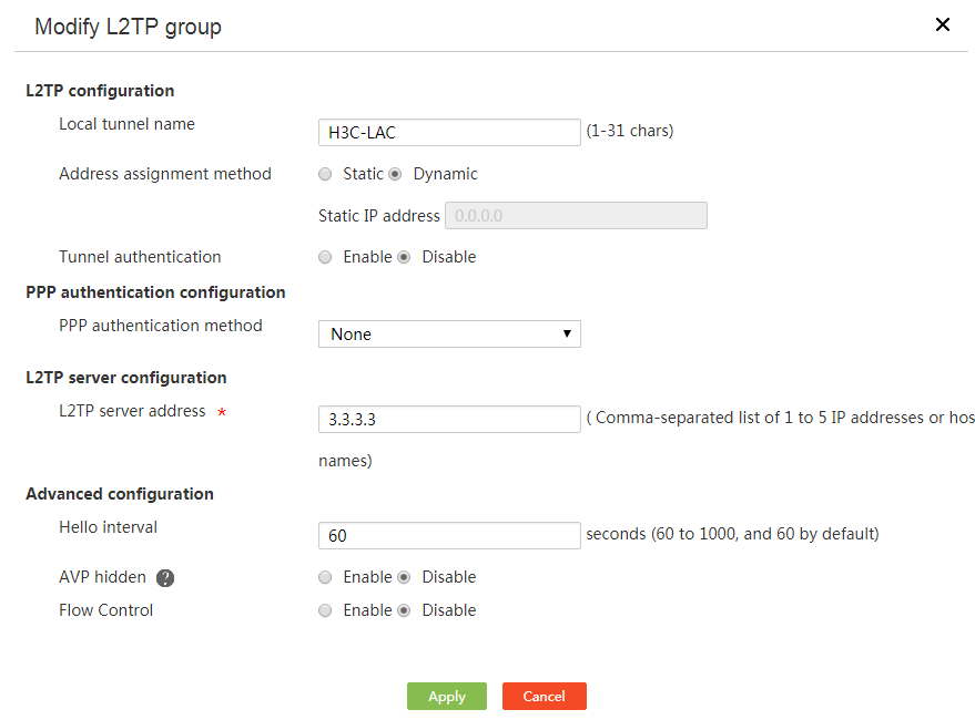
Delete L2TP groups
Procedure
1. From the navigation pane, select Virtual Network > L2TP Client.
2. Click the L2TP Config tab.
3. Perform one of the following tasks:
¡ Click Delete for an L2TP group.
¡ Select multiple L2TP groups, and then click Delete.
4. Click Yes.
Figure 110 Confirming the deletion

View L2TP tunnels
Procedure
1. From the navigation pane, select Virtual Network > L2TP Client.
2. Click the Tunnel Information tab.
Figure 111 L2TP tunnels
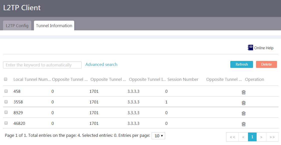
Delete L2TP tunnels
Procedure
1. From the navigation pane, select Virtual Network > L2TP Client.
2. Click the Tunnel Information tab.
3. Perform one of the following tasks:
¡ Click Delete for an L2TP tunnel.
¡ Select multiple L2TP tunnels, and then click Delete.
4. Click Yes.
Figure 112 Confirming the deletion

EoGRE
Introduction to EoGRE
Ethernet over GRE (EoGRE) is a tunneling protocol that can encapsulate the Ethernet protocol into a virtual point-to-point tunnel over an IP network. Ethernet frames are encapsulated at one tunnel end and de-encapsulated at the other tunnel end.
EoGRE supports EoGRE tunnel mode and EoGRE-in-UDP tunnel mode. Set the tunnel mode to EoGRE-in-UDP only if Layer 2 Ethernet packets are forwarded across a Layer 3 network with NAT traversal. If no NAT device is present, set the tunnel mode to EoGRE.
Configure an EoGRE tunnel
Restrictions and guidelines
Specify the tunnel mode when you create the EoGRE tunnel. The tunnel mode cannot be changed after tunnel creation.
Procedure
1. From the navigation pane, select Virtual Network > EoGRE.
2. Click the EoGRE Tunnels tab.
Figure 113 EoGRE tunnels
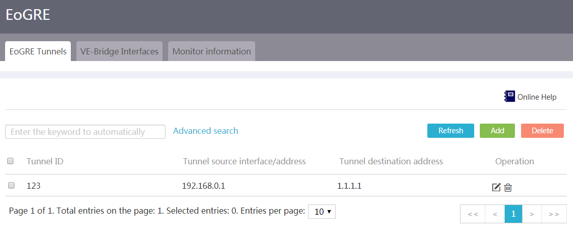
3. Click Add.
4. Configure EoGRE tunnel parameters.
¡ In the Tunnel ID field, enter a tunnel ID.
¡ In the Tunnel source field, select a tunnel source interface or configure a tunnel source address.
5. In the Tunnel destination address field, configure the tunnel destination IP address.
6. Click Show advanced settings to set the tunnel mode.
¡ To set the tunnel mode to EoGRE-in-UDP, select the UDP encapsulation option. You can use the default UDP port number or specify another UDP port number.
¡ To set the tunnel mode to EoGRE, clear the UDP encapsulation option.
7. Click Apply.
Figure 114 Add an EoGRE tunnel
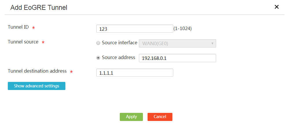
Configure a VE-Bridge interface
Restrictions and guidelines
· If a tunnel interface or GE interface has been bound to one VE-Bridge interface, you can bind the tunnel or GE interface to another VE-Bridge interface. However, the original binding is automatically removed from the first VB-Bridge interface.
· The GE interface bound to a VE-Bridge interface can perform only Layer 2 forwarding. Configuration of other services cannot take effect on the GE interface.
Procedure
1. From the navigation pane, select Virtual Network > EoGRE.
2. Click the VE-Bridge Interfaces tab.
Figure 115 VE-Bridge interfaces
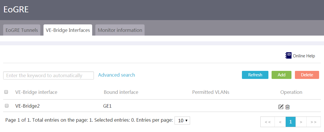
3. Click Add.
4. In the Interface number field, enter the number of the VE-Bridge interface.
5. In the Default VLAN field, set the PVID of the VE-Bridge interface.
6. In the Link type field, select a link type.
¡ To allow traffic only from the default VLAN to pass through the interface, select Access.
¡ To allow traffic from multiple VLANs to pass through the interface, select Trunk and specify the IDs of permitted VLANs.
7. In the Bound interface field, bind an interface to the VE-Bridge interface for Layer 2 forwarding.
¡ To bind a tunnel interface to the VE-Bridge interface, select the Tunnel interface option and select an EoGRE tunnel interface. Alternatively, you can select No bound interface to bind no tunnel interface to the VE-Bridge interface.
¡ To bind a Layer 3 interface to the VE-Bridge interface, select the GE interface option and select a Layer 3 interface. Alternatively, you can select No bound interface to bind no Layer 3 interface to the VE-Bridge interface.
8. Click Apply.
Figure 116 Add a VE-Bridge interface
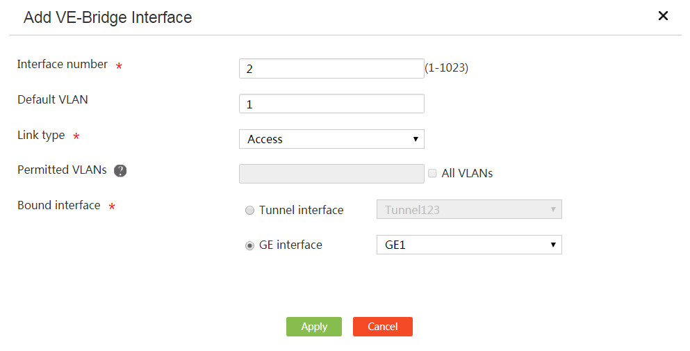
View monitor information
1. From the navigation pane, select Virtual Network > EoGRE.
2. Click the Monitor information tab.
3. View EoGRE tunnel ID, status, source interface or address, and destination address information.
If a tunnel is in up state, it can correctly forward packets. If a tunnel is in down state, it cannot forward packets.
Figure 117 EoGRE tunnel monitor information
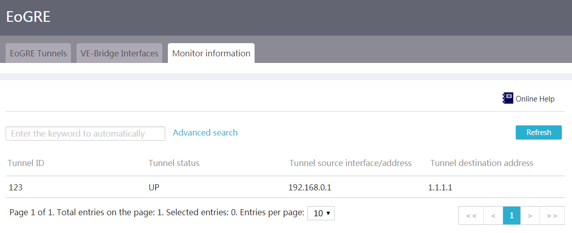
Advanced settings
Application services
Introduction to application services
Application services allow you to configure Domain Name System (DNS). DNS is a distributed database used by TCP/IP applications to translate domain names into IP addresses. The domain name-to-IP address mapping is called a DNS entry. DNS can be static or dynamic.
Static DNS
Static DNS (SDNS) allows you to manually create mappings between domain names and IP addresses. When you use a domain name to access a service (for example, a Web, mail, or FTP service), the system will look up the DNS cache for the IP address mapped to the domain name.
Dynamic DNS
Dynamic DNS (DDNS) can dynamically update the mappings between domain names and IP addresses for DNS servers.
In some scenarios, for example, the dial-up access scenario, a WAN interface is used to provide Web, mail, or FTP service, and the interface IP address changes. To allow users to access the service through a fixed domain name, you can configure DDNS on the WAN interface. When the IP address of the WAN interface changes, the device automatically sends packets to the DDNS server to update the domain name-IP address mapping.
Configure static DNS
1. From the navigation pane, select Advanced Settings > Application Services.
2. On the SDNS tab, click Add. The New SDNS Entry page opens.
Figure 118 SDNS
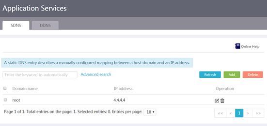
3. In the Domain name field, enter the domain name of the network device.
4. In the IP address field, enter the IP address of the network device.
5. Click Apply.
Figure 119 Adding an SDNS entry
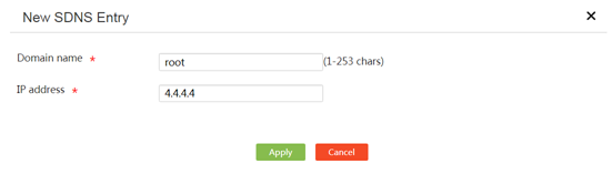
Configure dynamic DNS
Restrictions and guidelines
Make sure the WAN interface uses a public IP address when the device applies for a domain name from the DDNS server.
Prerequisites
Before configuring DDNS, go to the website of a DDNS service provider (for example, PeanutHull), and register an account.
Procedure
1. From the navigation pane, select Advanced Settings > Application Services.
2. Click the DDNS tab.
Figure 120 DDNS
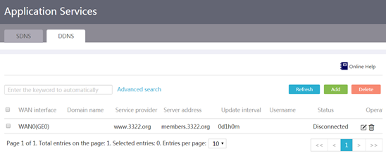
3. Click Add. The New DDNS Policy page opens.
4. On the page that opens, select the WAN interface that provides Web, mail, or FTP service from the WAN interface list.
5. In the Domain name field, enter the domain name of the device.
6. Configure the following DDNS server parameters:
¡ Select a service provider (for example, PeanutHull) from the Service provider list.
¡ In the Server address filed, enter the DDNS server address. If the server address is different from the default setting, select Modify server address to modify the IP address.
¡ Set the interval for the device to send DDNS update requests. If you set the interval to 0, the device sends update requests only when the WAN interface address changes or the WAN interface comes up from the down state.
7. In the Username and Password fields, enter the username and password that have been registered with the DDNS server, respectively.
8. Click Apply.
Figure 121 Adding a DDNS policy
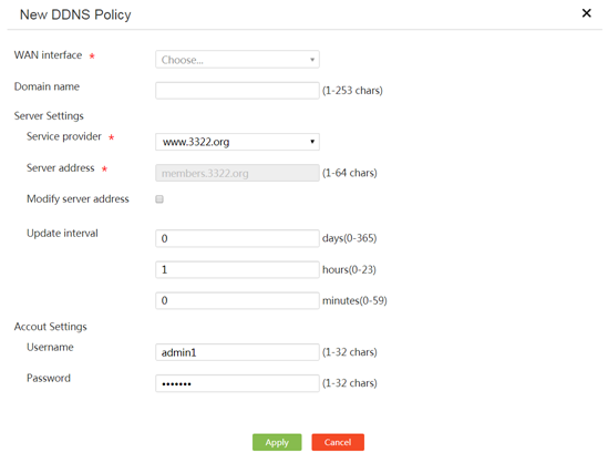
Static routing
Introduction
Static routes are manually configured. If a network's topology is simple and stable, you only need to configure static routes for the network to work correctly. For example, you can configure a static route based on the network egress interface and the gateway IP address for correct communication.
If multiple static routes are available to reach the same destination, you can assign different preference values to the static routes. The lower the preference value of a static route, the higher the priority of the route.
Restrictions and guidelines
If the interface associated with the next hop in a static route becomes invalid, the static route will not be deleted from the local device. To resolve this issue, you need to check your network environment and edit the static route settings.
Procedure
1. From the navigation pane, select Advanced Settings > Static Routing.
Figure 122 Static route list
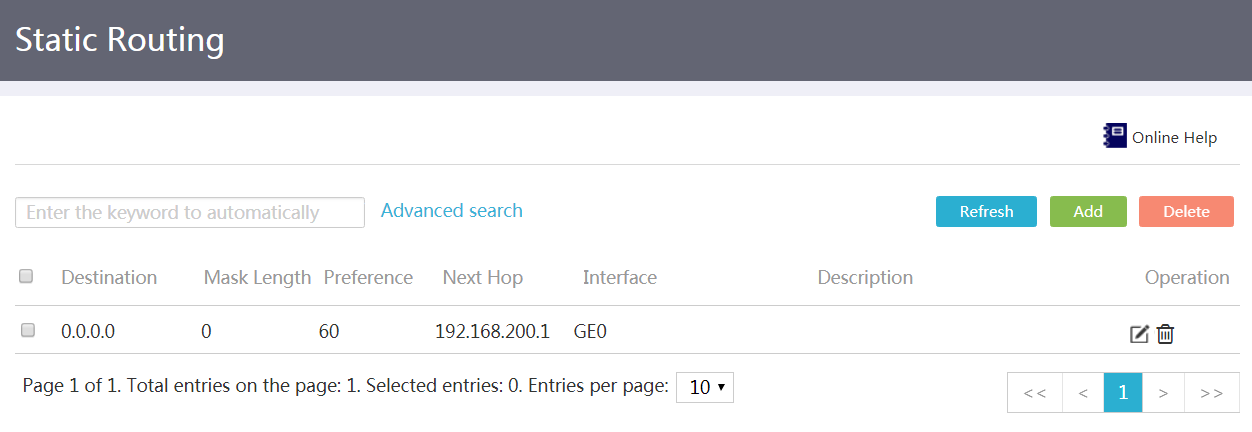
2. Click Add.
3. In the Destination IP address field, enter the destination network IP address of the static route.
4. In the Mask length field, enter the mask length of the destination network.
5. In the Next hop field, select an output interface and enter the next hop IP address of the static route.
¡ Select an output interface. Supported interface types include WAN, cellular, and VLAN interfaces.
¡ Enter a next hop IP address.
6. In the Preference field, enter a preference for the static route.
7. In the Description field, enter a description for the static route.
8. Click Apply.
Figure 123 Adding an IPv4 static route
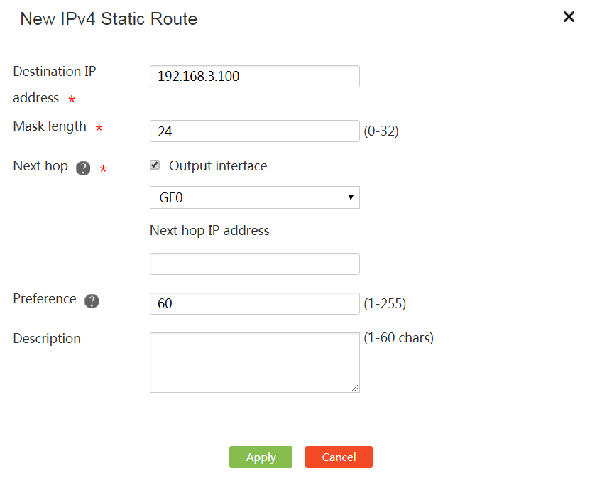
Policy-based routing
Introduction
Policy-based routing (PBR) enables you to forward packets flexibly based on packet characteristics by configuring a policy that contains a set of packet matching criteria and actions. For example, you can configure a PBR policy to forward packets with the specified source or destination IP address to the specified next hop or out of the specified interface.
Procedure
1. From the navigation pane, select Advanced Settings > PBR.
2. Select an interface to apply the PBR policy.
Figure 124 PBR policy list
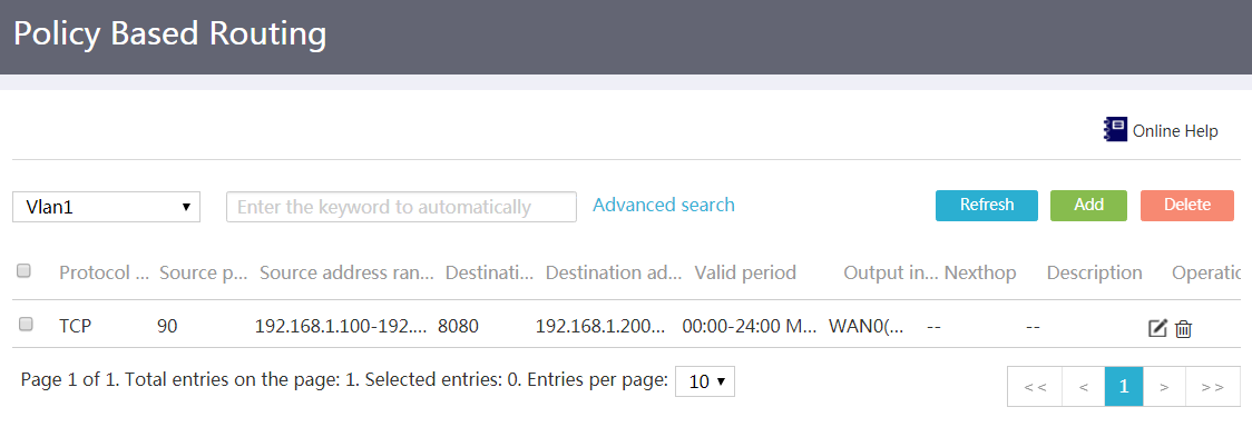
3. Click Add.
4. In the Match rule area, configure the matching criteria as needed:
¡ Select a protocol type in the Protocol type field.
- If you select Protocol number, you must enter the protocol number, for example, 80 (for HTTP).
- If you select TCP or UDP, you must enter the source and destination port numbers of the packets to match.
¡ In the Source address range and Destination address range fields, enter the source and destination IP address ranges. To specify an address range, separate the start and end IP addresses with a hyphen (-), for example, 1.1.1.1-1.1.1.2. To specify only one IP address, enter that IP address as both start and end IP addresses, for example, 1.1.1.1-1.1.1.1.
¡ In the Source port and Destination port fields, enter the source and destination ports. The Source port and Destination port fields are required only when the protocol type is TCP or UDP.
¡ In the Valid period section, specify the period of time in which the PBR policy takes effect. To specify a whole day, set the period to 00:00-23:59.
5. In the Output interface or Next hop field, set the output interface or next hop for the matching packets.
6. To facilitate management, enter a description for the PBR policy in the Description field.
7. Click Apply.
Figure 125 Configuring PBR policy settings
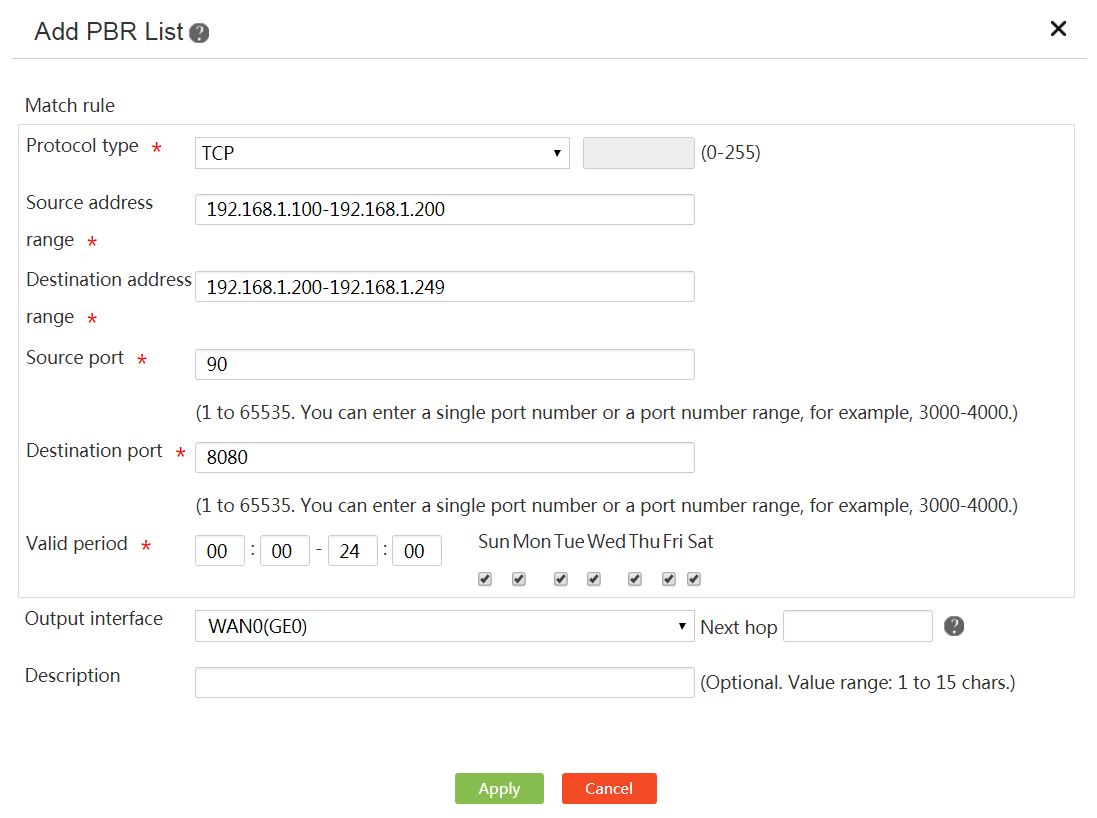
SNMP
Introduction to SNMP
Simple Network Management Protocol (SNMP) allows you to use a network management system (NMS), such as MIB Browser, to access and manage devices. With SNMP configured, devices automatically send traps or informs to the NMS when a critical event (such as interface going up or coming down, high CPU utilization, and memory exhaustion) occurs.
The device supports SNMPv1, SNMPv2c, and SNMPv3. SNMPv3 offers greater security than SNMPv1 and SNMPv2c.
· SNMPv1 and SNMPv2c use passwords for authentication.
· SNMPv3 uses a username for authentication and you must configure an authentication key and a privacy key to ensure communication security.
¡ The username and authentication key are used to authenticate the NMSs to prevent invalid NMSs from accessing the device.
¡ The privacy key is used to encrypt the messages transmitted between the NMS and the device to prevent the messages from being eavesdropped.
Prerequisites
Determine the SNMP version to use. The NMS and device must use the same SNMP version.
Configure SNMPv1 or SNMPv2c
Restrictions and guidelines
The NMS and device must use the same SNMP passwords. SNMP passwords include read-only password and read-write password. A minimum of one must be configured.
· To obtain parameter values from the device, configure only a read-only password.
· To obtain and set parameter values on the device, configure a read and write password.
Procedure
1. From the navigation pane, select Advanced Settings > SNMP.
2. Enable SNMP.
3. Select the SNMPv1 and SNMPv2c version.
4. Specify the SNMP password.
5. Enter the IP address of an NMS in the Trust Host IPv4 Address field.
Only the specified NMS can manage the device. If you do not configure this parameter, all NMSs that use correct SNMP passwords can manage the device.
6. Enter the IP address or domain name of the host to receive the notifications in the Trap Target Host IPv4 Address/Domain field.
7. Enter the contact information of the device administrator in the Contact Information field.
8. Enter the physical location of the device in the Device Location field.
9. Click Apply.
Figure 126 Configuring SNMPv1 and SNMPv2c
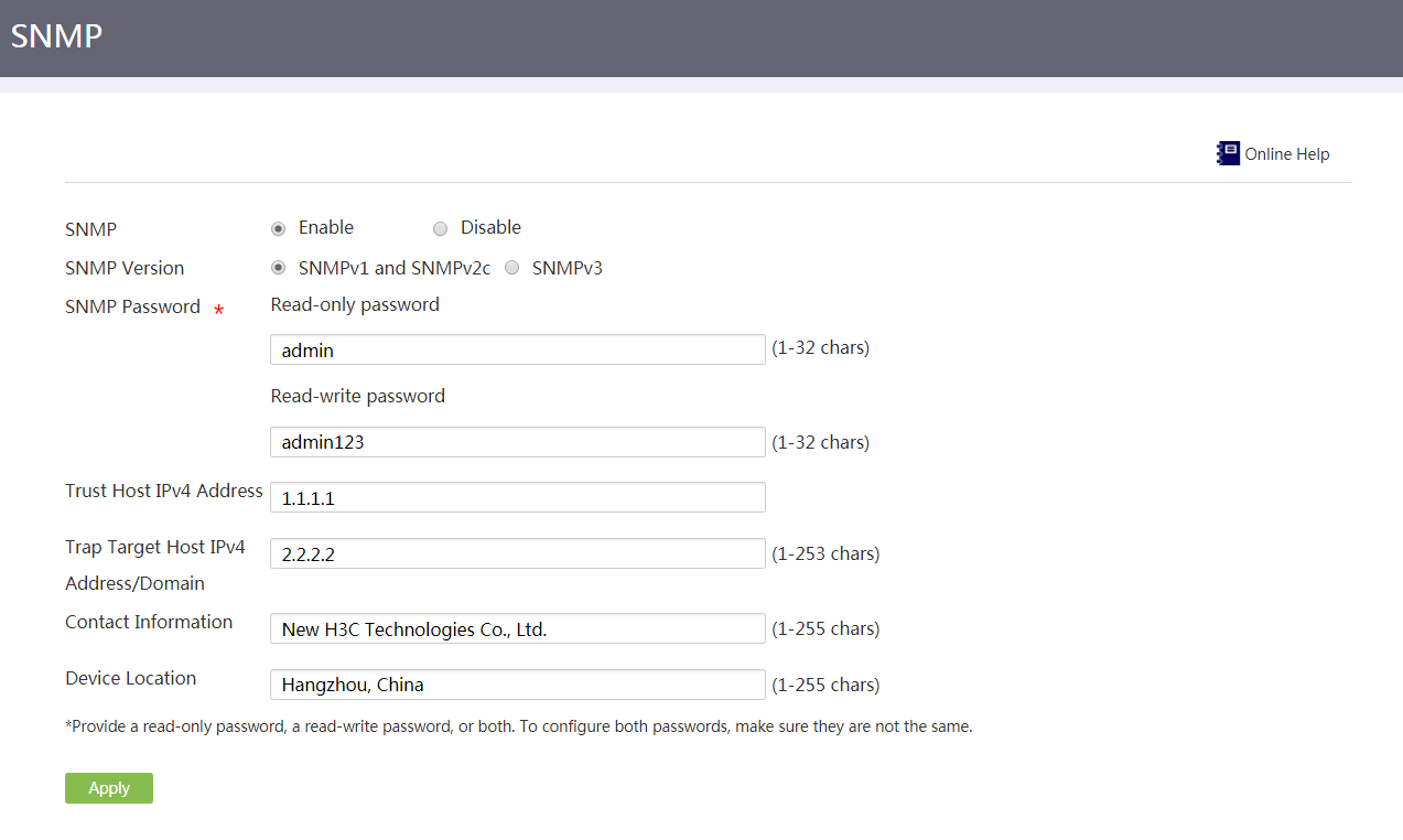
Configure SNMPv3
Restrictions and guidelines
The NMS and device must use the same username, authentication key, and privacy key.
Procedure
1. From the navigation pane, select Advanced Settings > SNMP.
2. Enable SNMP.
3. Select the SNMPv3 version.
4. Specify the username.
5. Specify the authentication key.
6. Specify the privacy key.
7. Enter the IP address of an NMS in the Trust Host IPv4 Address field.
Only the specified NMS can manage the device. If you do not configure this parameter, all NMSs that use the correct SNMP username, authentication key, and privacy key can manage the device.
8. Enter the IP address or domain name of the host to receive notifications in the Trap Target Host IPv4 Address/Domain field.
9. Enter the contact information of the device administrator in the Contact Information field.
10. Enter the physical location of the device in the Device Location field.
11. Click Apply.
Figure 127 Configuring SNMPv3
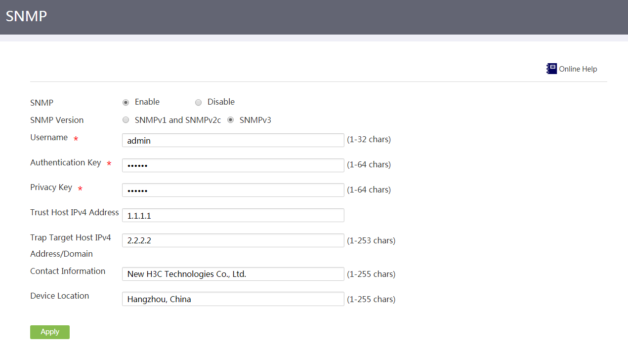
CWMP
Introduction to CWMP
In a CPE WAN Management Protocol (CWMP) network, you can manage CPEs (Customer Premises Equipment) in bulk from the Auto-Configuration Server (ACS) remotely and uniformly, which resolves issues in CPE management and saves maintenance cost.
Prerequisites
Prepare a server that supports ACS features and configure the ACS server settings in advance.
Procedure
1. From the navigation pane, select Advanced Settings > CWMP.
2. Enable CWMP.
3. In the ACS area, enter the URL address, username, and password for the ACS.
The connection request initiated by a CPE to the ACS contains ACS username and password. The ACS accepts the request only when the ACS username and password in the request are the same as those configured locally for the ACS server.
4. In the CPE area, perform the following tasks:
a. Specify the CPE username and password.
To avoid malicious control on a CPE, the ACS sends a management instruction that carries the CPE username and password. The ACS is able to control the CPE only when the username and password in the instruction are the same as those configured locally for the CPE.
b. Enable or disable periodic inform as needed. If you enable this feature, configure the inform packet sending intervals.
A CPE initiates a connection request to the ACS by sending an inform packet that contains the usernames and passwords of the CPE and ACS, respectively.
To make a device connect to the ACS at certain intervals automatically, you must enable the periodic inform feature.
c. Specify an interface on the CPE to connect to the ACS.
5. Click Certain.
Figure 128 Configuring CWMP
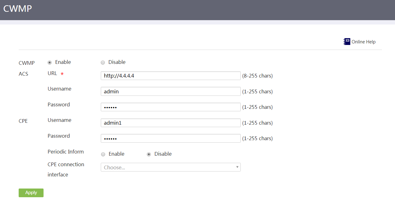
System tool
Basic settings
Introduction to basic settings
Perform this task to configure device information and system time.
The device information includes device name, device location, and contact information. The device name is editable, but the device location and contact information cannot be edited.
The system time includes date, time, and time zone. Correct system time is essential to network management and communication. Configure the system time correctly before you run the device on the network.
The device can use one of the following methods to obtain the system time:
· Manually set the system time.
The device uses the locally set system time, and then uses the clock signals generated by its built-in crystal oscillator to maintain the system time.
If the device restarts, the system time will restore to the factory default.
· Automatically synchronize date and time with an NTP server.
The device uses the time obtained from the NTP server as the current system time, and synchronizes time with the NTP server periodically. The device will quickly resynchronize the system time with the NTP server even if the device restarts. If you have an NTP server on the network, this method is recommended.
The system time calculated by using the time from a time source is more precise.
|
|
NOTE: As a best practice, use one of the following browsers to access the Web interface: · Internet Explorer 10 or later. · Chrome 57 or later. · Firefox 35 or later. |
Configure basic device information
1. From the navigation pane, select System Tool > Basic Settings.
2. On the Device information tab, enter a device name.
3. Click Apply.
Figure 129 Device information
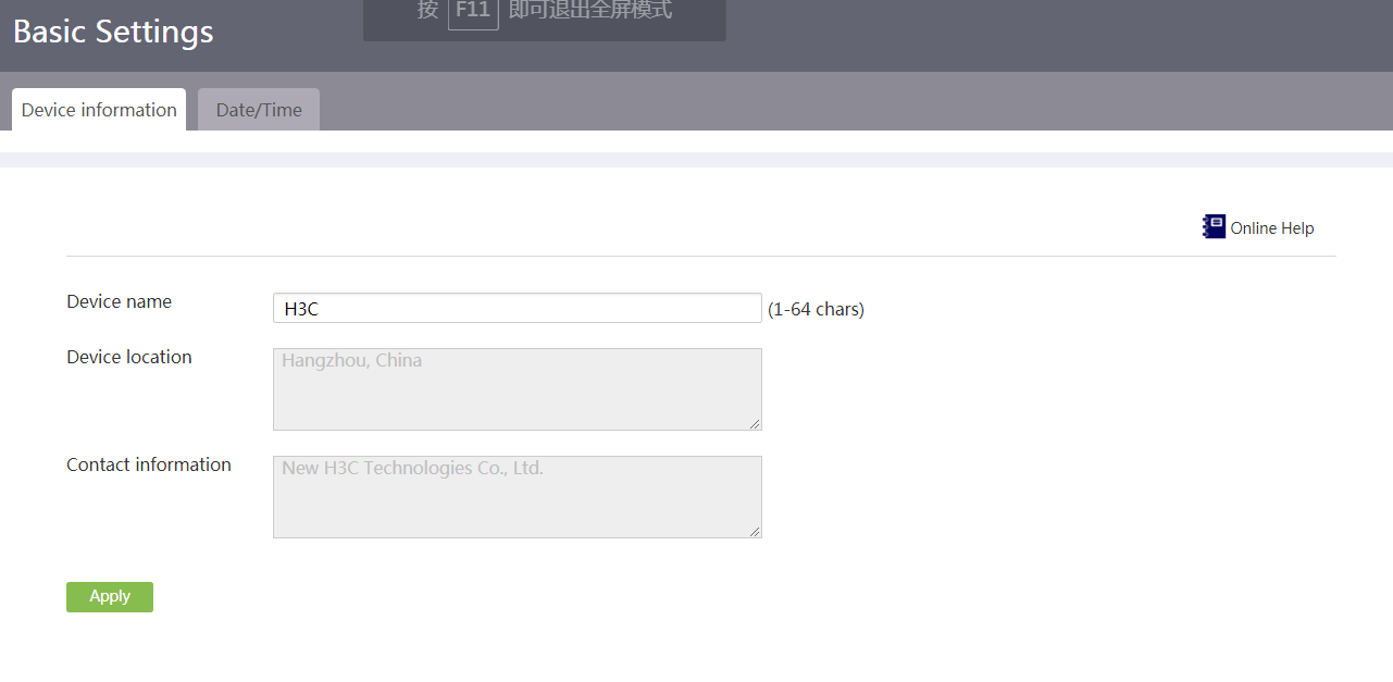
Manually configure the system time
Restrictions and guidelines
A device reboot restores the factory default system time settings.
Prerequisites
Identify the time zone of the place where the device resides.
Procedure
1. From the navigation pane, select System Tool > Basic Settings.
2. Click the Date/Time tab.
3. Select Manually set the clock.
4. Set the system time to the current time in the geographic area where the device is located:
a. Select the date.
b. Select the time. The minute and second values available on the Web interface are multiples of 3 (00, 03, 06, 09, ..., 57). You can use the up or down arrows to fine tune the values. For example, to set the minute value to 20, select 18 first, and then click the up arrow twice to get 20.
5. Select the time zone of the place where the device resides.
6. Click Apply.
Figure 130 Configuring the system time manually
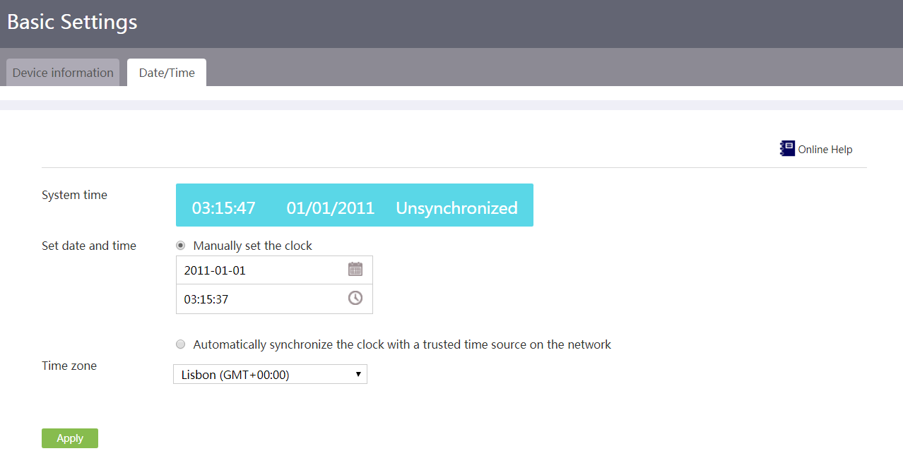
Automatically synchronize the UTC time
Restrictions and guidelines
Make sure the device uses the same time zone as the NTP server.
Prerequisites
Identify the time zone of the place where the device resides.
Procedure
1. From the navigation pane, select System Tool > Basic Settings.
2. Click the Date/Time tab.
3. Select Automatically synchronize the clock with a trusted time source on the network.
4. Click Default NTP Server List to identify the default NTP servers.
5. Specify NTP servers by entering their IP addresses or host names.
6. Select the time zone.
7. Click Apply.
Figure 131 Synchronizing the UTC time automatically
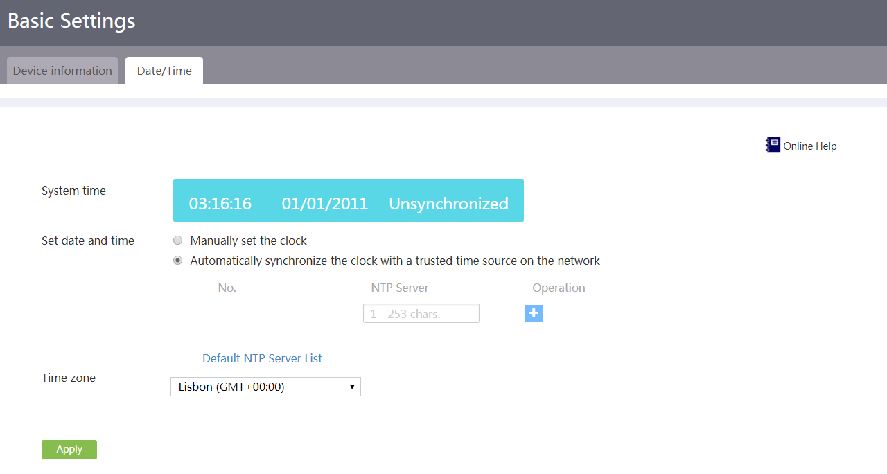
|
|
NOTE: · Whether default NTP servers are configured for the device depends on the device model. · You can use default NTP servers or specify NTP servers as needed. The device automatically obtains the UTC time from an available NTP server that provides highest time precision. If none of NTP servers is available, the device uses its internal clock signal. After an NTP server recovers, the device will synchronize time with the NTP server again. |
Diagnostics
Introduction to diagnostics
Use this feature to diagnose network faults. With diagnostics, you can perform the following tasks:
· Tracert—Traces the path that packets traverse from the device to the destination host.
· Ping—Tests the reachability of another device or host.
· Diagnostic export—Collects the operating information of feature modules for system diagnostics and troubleshooting. The device will automatically store collected information in a compressed file and save the file on your Web login terminal.
· Port mirroring—Automatically copies packets passing through a monitored port to the monitor port and provides transmission information on each port in real time. The network administrator can use the information to perform traffic monitoring, performance analysis, and fault diagnosis.
· Packet capture tool—Captures network data packets to more effectively analyze network faults. The tool uses tcpdump to run at the backend and automatically stores the captured packets to a file named flash--packetCapture.pcap on your Web login terminal.
Configure tracert
1. From the navigation pane, select System Tool > Diagnostics.
2. Click the Tracert tab.
3. Enter the destination IP address or host name.
4. Click Start.
5. In the Result area, view the tracert result.
Figure 132 Configuring Tracert
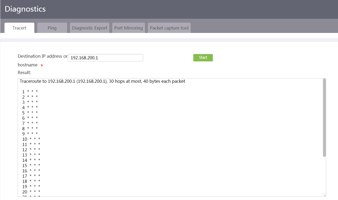
Configure ping
1. From the navigation pane, select System Tool > Diagnostics.
2. Click the Ping tab.
3. Enter the destination IP address or host name.
4. Configure a source interface or source IP address for ping packets.
5. Click Start.
6. In the Result area, view the ping result.
Figure 133 Configuring ping
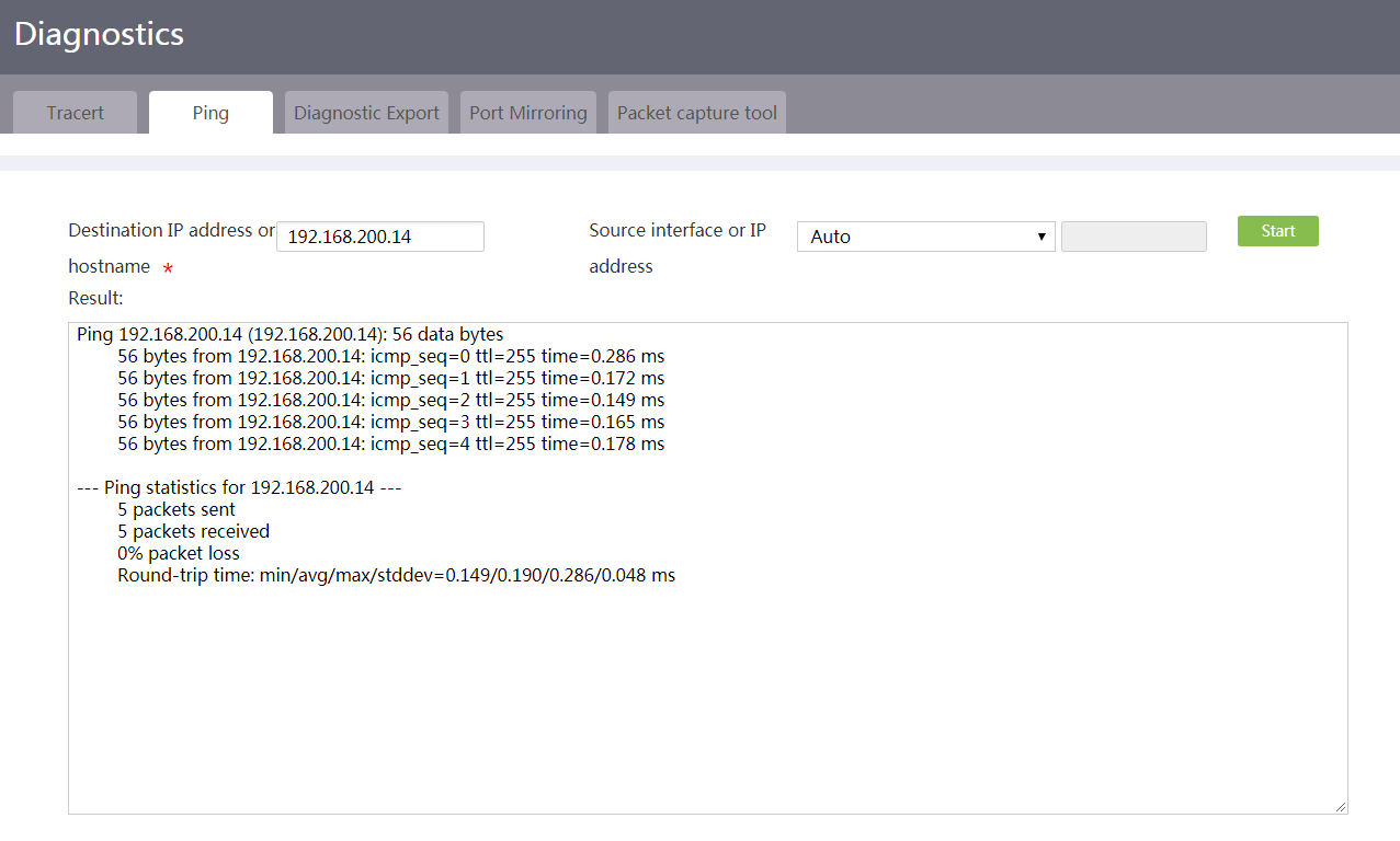
Collect diagnostic information
1. From the navigation pane, select System Tool > Diagnostics.
2. Click the Diagnostic Export tab.
3. Click Collect.
Figure 134 Collecting diagnostic information
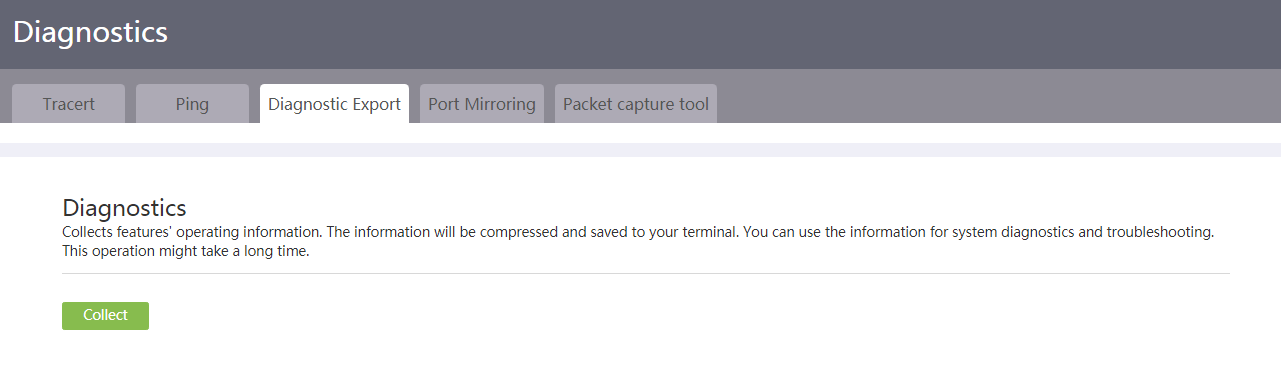
Configure port mirroring
1. From the navigation pane, select System Tool > Diagnostics.
2. Click the Port Mirroring tab.
3. Select to configure port mirroring for Layer 2 or Layer 3 interfaces.
4. Configure source ports.
Select a source port. Then select a direction for the source port. The following options are available:
¡ Inbound: Mirror only packets received on the source port.
¡ Outbound: Mirror only packets sent from the source port.
¡ Both: Mirror both packets received on the source port and packets sent from the source port.
To add more source ports, click the + icon.
5. Select a destination port.
6. Click Ensure.
Figure 135 Configuring port mirroring
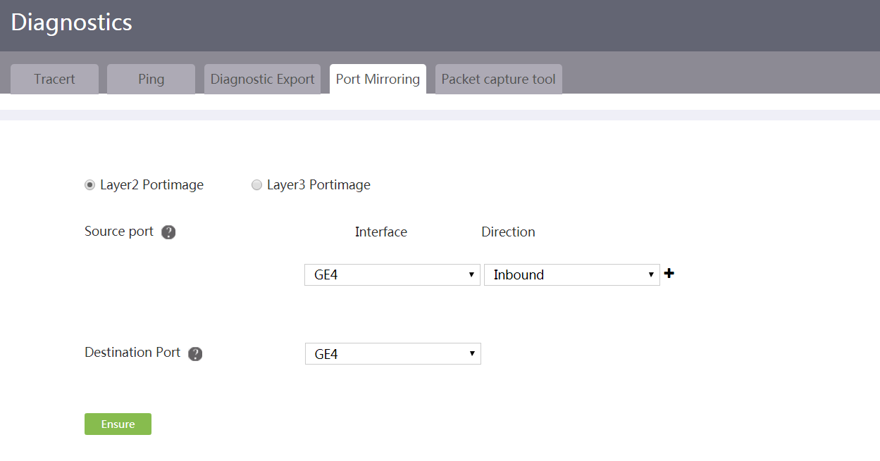
Configure the packet capture tool
Restrictions and guidelines
Before using this feature, make sure the storage medium has sufficient space to store the packet capture file. If the storage space is insufficient, the packet capture task will be stopped before it is completed.
Procedure
1. From the navigation pane, select System Tool > Diagnostics.
2. Click the Packet capture tool tab.
3. Select the interface on which packets are to be captured.
Any WAN interface on the router can be selected.
4. Configure the size of packets to be captured, in bytes. The capture length parameter represents the maximum length that the device can capture from a packet. If the length of a packet is longer than the specified length, the device captures only contents of the specified length from that packet.
A long capture length increases the packet processing time and reduces the number of packets that tcpdump can cache, which might result in packet loss. On the premise that the required packets can be captured, specify a smaller capture length.
5. Specify protocol types for capturing packets as needed. If you select all, all packets on the interface will be captured.
6. Set the maximum size of the file that stores captured packets, in MB.
7. Set the packet capture duration, in seconds.
8. Filter packets to be captured by source host parameters. The following options are available:
¡ Any: Capture packets for all source hosts.
¡ Filter by IP address: Capture packets sourced from a host with a specific IP address.
¡ Filter by MAC address: Capture packets sourced from a host with a specific MAC address.
9. Filter packets to be captured by destination host parameters. The following options are available:
¡ Any: Capture packets for all destination hosts.
¡ Filter by IP address: Capture packets received by a host with a specific IP address.
¡ Filter by MAC address: Capture packets received by a host with a specific MAC address.
10. Click Start.
The packet capture process and the number of packets currently captured are displayed on the current page. You can click Cancel to terminate packet capture and export the capture file flash -- packetCapture.pcap.
Figure 136 Configuring the packet capture tool
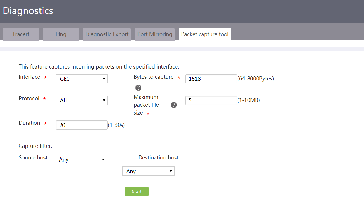
Admin account management
About admin account management
Use this page to manage and maintain the admin accounts used by users to log in to the device. You can add, edit, or delete admin accounts.
Add an admin account
1. From the navigation pane, select System Tool > Admin Accounts.
Figure 137 Admin accounts
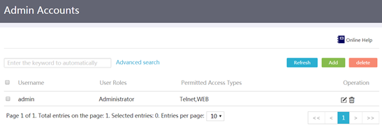
2. Click Add.
3. In the dialog box that opens, enter an account name in the Username field.
4. Enter a password in the Password field and confirm it in the Confirm password field.
If you do not configure a password, no password is required by the system when a user uses this account to log in to the device. To improve security, configure a password for the admin account.
5. In the User roles field, select user roles.
¡ To assign the highest administrative privilege to this admin account, select Administrator.
¡ To assign only the view privilege to this admin account, select Operator.
6. In the Permitted access types field, select access services.
¡ To assign the console service to this admin account, select Console.
The console service allows users to log in to the device through the console port.
¡ To assign the Telnet service to this admin account, select Telnet.
The Telnet service allows users to Telnet to the device from a Telnet client when the device acts as a Telnet server.
¡ To assign the FTP service to this admin account, select FTP.
The FTP service allows users to access the file system resources on the device from an FTP client when the device acts as an FTP server.
¡ To assign the Web service to this admin account, select WEB.
The Web service allows users to log in to the device through Web.
¡ To assign the SSH service to this admin account, select SSH.
The SSH service allows users to log in to the device from an SSH client when the device acts as an SSH server. SSH login is safer than Telnet login.
7. In the Max concurrent online users field, set the maximum number of concurrent users that can use this admin account.
If you do not set a limit, the device does not limit the number of concurrent users that use this admin account.
This setting does not limit the number of concurrent users that use this admin account to log in to the device through FTP.
8. In the FTP working directory field, enter a working directory. You must configure this parameter if the admin account is assigned the FTP service.
As a best practice to enter a valid working directory, first access the System Tool > Upgrade > File Management page to view existing file paths.
9. Click Apply.
Figure 138 Adding an admin account
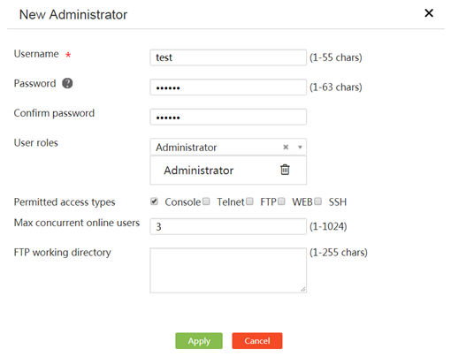
Edit an admin account
1. From the navigation pane, select System Tool > Admin Accounts.
2. Click the Edit icon in the Operation column for an admin account.
3. In the dialog box that opens, enter a new password in the Change password field and confirm it in the Confirm password field.
After you change the password of an admin account, users that use this admin account must change the password again at the next login.
4. In the User roles list, select a new role.
¡ To assign the highest administrative privilege to this admin account, select Administrator.
¡ To assign only the view privilege to this admin account, select Operator.
5. In the Permitted access types field, select new access services.
¡ To assign the console service to this admin account, select Console.
The console service allows users to log in to the device through the console port.
¡ To assign the Telnet service to this admin account, select Telnet.
The Telnet service allows users to Telnet to the device from a Telnet client when the device acts as a Telnet server.
¡ To assign the FTP service to this admin account, select FTP.
The FTP service allows users to access the file system resources on the device from an FTP client when the device acts as an FTP server.
¡ To assign the Web service to this admin account, select WEB.
The Web service allows users to log in to the device through Web.
¡ To assign the SSH service to this admin account, select SSH.
The SSH service allows users to log in to the device from an SSH client when the device acts as an SSH server. SSH login is safer than Telnet login.
6. In the Max concurrent online users field, set a new value to change the maximum number of concurrent users that can use this admin account.
If you do not set a limit, the device does not limit the number of concurrent users that use this admin account.
This setting does not limit the number of concurrent users that use this admin account to log in to the device through FTP.
7. In the FTP working directory field, enter a new working directory. You must configure this parameter if the admin account is assigned the FTP service.
As a best practice to enter a valid working directory, first access the System Tool > Upgrade > File Management page to view existing file paths.
8. Click Apply.
Figure 139 Editing an admin account
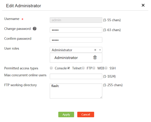
Delete an admin account
1. From the navigation pane, select System Tool > Admin Accounts.
2. Click the Delete icon in the Operation column for an admin account.
3. In the dialog box that opens, click Yes.
Remote management
Introduction to remote management
Use remote management to configure parameters for network connectivity detection or device remote login and management.
With remote management, you can perform the following tasks:
· Permit ping on interfaces—Perform this task to permit interfaces to send ping packets. Ping is a utility for detecting network connectivity and obtaining the running status of the network.
· Permit Telnet login on interfaces—Perform this task to allow users to Telnet to the device through specific interfaces. Telnet is a remote login protocol. Users can Telnet to the device from a PC to remotely manage the device.
· Permit SSH login—To secure device access, perform this task to enable the Secure Shell (SSH) services. SSH is a network security protocol. Using encryption and authentication, SSH can implement secure remote access and file transfer over an insecure network. Acting as an SSH server, the device supports the following SSH services:
¡ Stelnet—The implementation of Secure Telnet (Stelnet) is the same as that of Telnet, but Stelnet is more secure.
¡ SFTP—Secure FTP (SFTP) uses SSH connections to provide secure file transfer. The device allows a remote user to log in to it for secure file management and transfer.
¡ SCP—Secure Copy (SCP) offers a secure method to copy files.
· Permit HTTP/HTTPS login on interfaces—Perform this task to allow users to use HTTP or HTTPS to log in to the device through specific interfaces. Web login can use HTTP or HTTPS. HTTPS login is more secure than HTTP login. Users can use HTTP or HTTPS to log in to the Web interface of the device from a PC for remote device configuration and management.
· Use the cloud service—Perform this task to establish a remote management tunnel with an H3C Cloud server through the Internet. The network administrator can remotely manage and maintain the device through the Cloud server.
Permit ping on an interface
1. From the navigation pane, select System Tool > Remote Login.
2. On the Ping tab, select Permit ping for an interface to permit the interface to send ping packets.
3. Click Apply.
Figure 140 Configure ping service
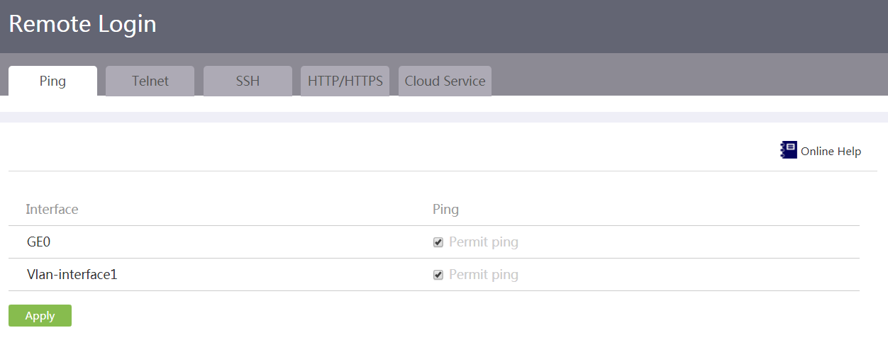
Configure Telnet login
1. From the navigation pane, select System Tool > Remote Login.
2. Click the Telnet tab.
3. Click the button next to the Telnet service field to enable the Telnet service. When the Telnet service is in ON state, the service is enabled.
4. In the IPv4 Listening Port or IPv6 Listening Port field, enter a port number for the Telnet service.
Enter the IPv4 listening port number or IPv6 listening port number depending on the network requirements.
¡ If users Telnet to the device in an IPv4 network, the port number used by the users must be the same as that specified in the IPv4 Listening Port field.
¡ If users Telnet to the device in an IPv6 network, the port number used by the users must be the same as that specified in the IPv6 Listening Port field.
5. Click Apply.
Figure 141 Configure Telnet service
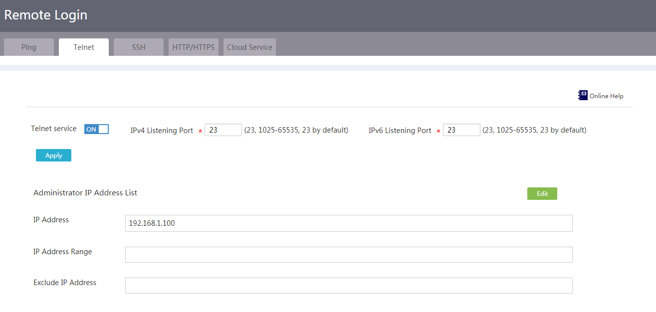
6. Click Edit on the right side of Administrator IP Address List.
7. On the page that opens, specify one or multiple IPv4 addresses of the interface for remote login:
¡ To add an individual administrator IP address, enter the IP address in the IP address field.
¡ To add a range of administrator IP addresses, specify the IP address range in the IP address range field.
The start address must be lower than the end address. The IP address specified individually can be out of the specified IP address range.
¡ To exclude an IP address from the IP address range, enter the excluded IP address in the Exclude IP address field.
The excluded IP address must be in the specified IP address range. An excluded IP address cannot access the device through Telnet.
8. Click the ![]() icon to add the specified IP address, address range, or/and
excluded IP address to the administrator IP address list at
right.
icon to add the specified IP address, address range, or/and
excluded IP address to the administrator IP address list at
right.
9. Repeat steps 7 to 8 to add more administrator IP addresses.
10. Click Apply.
Figure 142 Configure administrator IP addresses
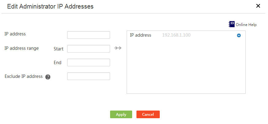
Configure SSH login
1. From the navigation pane, select System Tool > Remote Login.
2. Click the SSH tab.
3. Enable one or multiple SSH services according to the network requirements:
¡ To enable the Stelnet service, click the button next to the Stelnet service field to set the service state to ON.
¡ To enable the SFTP service, click the button next to the SFTP service field to set the service state to ON.
¡ To enable the SCP service, click the button next to the SCP service field to set the service state to ON.
Figure 143 Configure SSH service
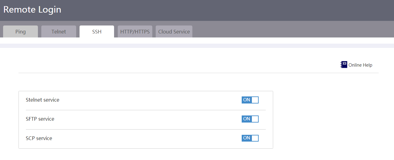
Configure HTTP login and HTTPS login
1. From the navigation pane, select System Tool > Remote Login.
2. Click the HTTP/HTTPS tab.
3. In the HTTP Service Port field, enter a port number for HTTP login. As a best practice, use a port number greater than 10000 for HTTP login.
4. In the HTTPS Service Port field, enter a port number for HTTPS login. As a best practice, use a port number greater than 10000 for HTTPS login.
5. Enter a timeout time in the Web Idle timeout field.
6. Click Apply.
Figure 144 Configure HTTP/HTTPS service
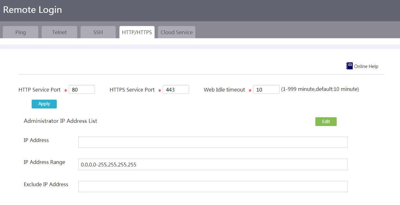
7. Click Edit on the right side of Administrator IP Address List.
8. On the page that opens, add administrator IP addresses:
¡ To add an individual administrator IP address, enter the IP address in the IP address field.
¡ To add a range of administrator IP addresses, specify the IP address range in the IP address range field.
The start address must be lower than the end address. The IP address specified individually can be out of the specified IP address range.
By default, the device allows Web access from IP address range 1.1.1.1–255.255.255.255. You can edit the address range as needed. Make sure the administrators can still access Web pages after IP address modification.
As a best practice, configure the administrator IP address list to contain the network segment where the VLAN interface connecting the user client resides.
¡ To exclude an IP address from the IP address range, enter the excluded IP address in the Exclude IP address field.
The excluded IP address must be in the specified IP address range. The device does not allow Web access from the excluded IP address.
9. Click the ![]() icon to add the specified IP address, address range, or/and
excluded IP address to the administrator IP address list at
right.
icon to add the specified IP address, address range, or/and
excluded IP address to the administrator IP address list at
right.
10. Repeat steps 8 to 9 to add more administrator IP addresses.
11. Click Apply.
Figure 145 Configure administrator IP addresses
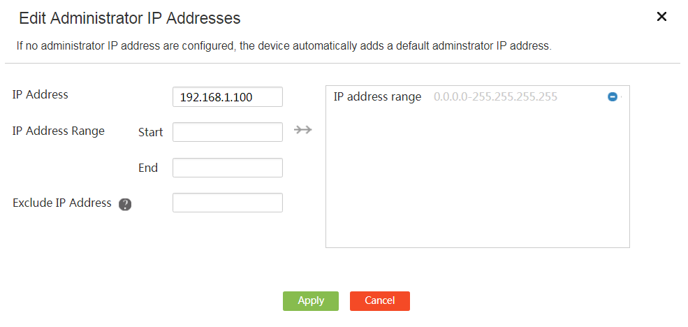
Configure the cloud service
1. From the navigation pane, select System Tool > Remote Login.
2. Click the Cloud Service tab.
3. Select Open from the Cloud Service field to enable the cloud service.
4. In the Server domain name field, enter the Cloud server domain name.
5. In the Sysname field, enter the system name of the device.
6. Click Apply.
7. Use a mobile phone to scan the QR code on the page to download and install the Cloudnet app. Then, open the app on the mobile phone to log in to the Cloud server to remotely manage and maintain the device.
Figure 146 Configure the cloud service
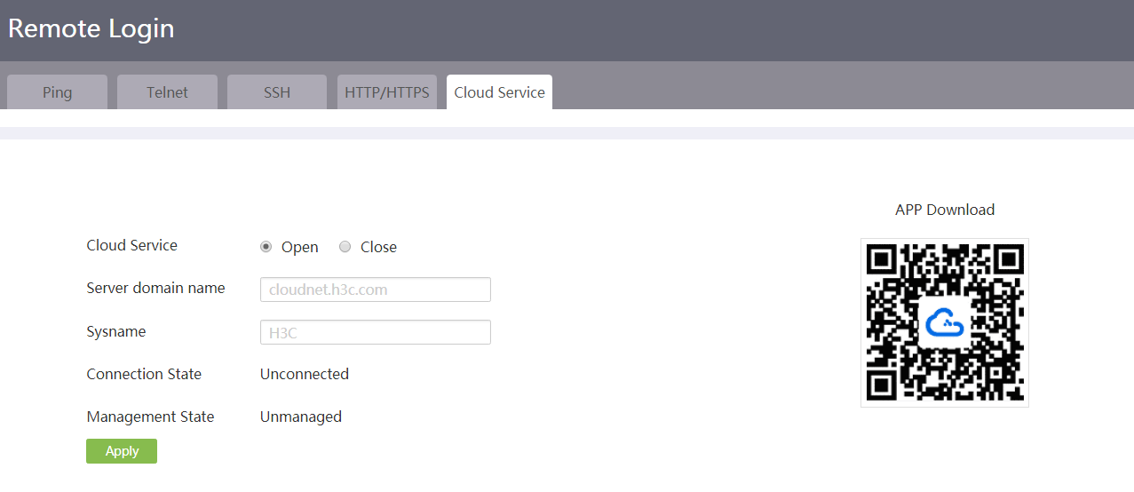
Configuration management
Introduction to configuration management
Use configuration management to manage the configuration files on the device.
With configuration management, you can perform the following tasks:
· View the running configuration—To view the running configuration on the device, for example, the software version and interface IP addresses, select System Tool > Config Management from the navigation pane and click the View Config tab.
· Restore the factory defaults—This task restores the configuration to the factory defaults. If the device does not have a startup configuration file or the startup configuration file is corrupt, perform this task so the device can start up at the next startup.
· Save the running configuration—This task saves the running configuration to the main next-startup configuration file, which is the primary next-startup configuration file. Perform this task after you complete one or multiple configuration tasks so the new settings you have made can survive a device reboot.
· Restore the configuration from a backup file—This task replaces the running configuration with the configuration from a backup file. Perform this task if the running configuration contains incorrect or undesirable settings.
· Export the running configuration—This task exports the running configuration to a configuration file. Perform this task to back up the running configuration for future use.
Restore the factory defaults
1. From the navigation pane, select System Tool > Config Management.
2. Click the Restore Config tab.
3. Click Reset.
Figure 147 Restoring the factory defaults
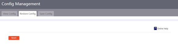
4. In the dialog box that opens, click Yes to confirm that you are sure to restore the factory default configuration and forcibly reboot the system.
Then, the device automatically reboots and restores the factory default configuration.
Save the running configuration
1. From the navigation pane, select System Tool > Config Management.
2. Click the Save Config tab.
3. Click Save Running Configuration.
Figure 148 Save Config page
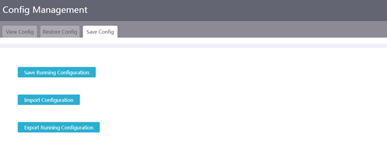
4. On the page that opens, use one of the following methods to save the running configuration to the main next-startup configuration file:
¡ to the next-startup configuration file—If you select this option, the system does not allow you to select a file. The system directly saves the running configuration to a file in the root directory of the storage medium and specifies the file as the main next-startup configuration file.
¡ to file—If you select this option, the system allows you to select a file to save the running configuration and specifies the file as the main next-startup configuration file.
Figure 149 Saving the running configuration
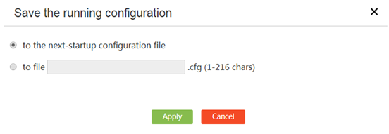
5. Click Apply.
Restore configuration from a backup file
1. From the navigation pane, select System Tool > Config Management.
2. Click the Save Config tab.
3. Click Import Configuration.
4. On the page that opens, click Choose File to select a backup configuration file.
Figure 150 Choosing a backup file
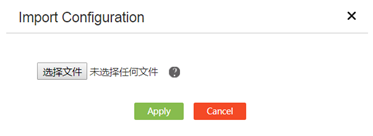
5. Click Apply.
6. Reboot the device.
Export the running configuration
1. From the navigation pane, select System Tool > Config Management.
2. Click the Save Config tab.
3. Click Export Running Configuration to export the running configuration to the local PC.
Software upgrade
Introduction
Use software upgrade to upgrade device software and manage the files on the device. You can add new feature or fix bugs by upgrading device software.
You can upgrade device software by using the following methods:
· Manual upgrade: Upgrade device software by using a local IPE file uploaded to the device.
· Auto upgrade: Upgrade device software by downloading the latest software image file from the cloud platform.
File management supports the following operations:
· Upload—Upload a file to the device. For example, you can upload an .ipe file to the device before using the file to upgrade the software on the device.
· Delete—Delete unimportant files from the device to release the storage space used by the files.
· Download—Download a file from the device to your PC for data backup or analysis.
Upgrade device software
Manually upgrade device software
1. From the navigation tree, select System Tool > Upgrade.
2. On the Upgrade tab, click Manual upgrade.
Figure 151 Upgrade
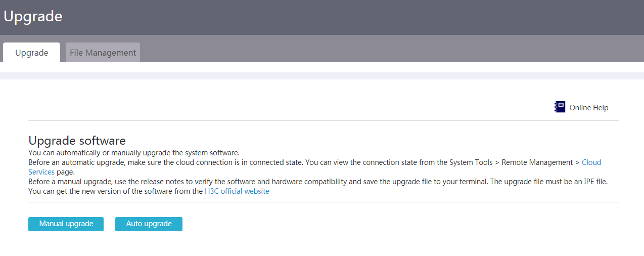
3. Click Select File, and select the target IPE file.
4. To load the device with the new software immediately, select Reboot Now.
5. Click OK.
Figure 152 Manually upgrading system software
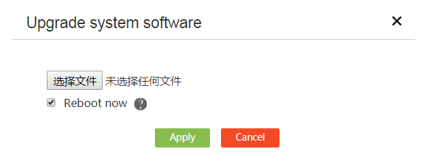
Automatically upgrade device software
· Restrictions and guidelines
Before an automatic upgrade, make sure the cloud connection is connected state. You can view the connection state from the System Tool > Remote Management > Cloud Services page.
· Procedure
1. From the navigation tree, select System Tool > Upgrade.
2. On the Upgrade tab, click Auto upgrade to download the latest software version from the cloud platform for automatic upgrade.
Figure 153 Automatically upgrading system software
Manage files
Upload a file
1. From the navigation tree, select System Tool > Upgrade.
2. Click the File System tab.
Figure 154 File management
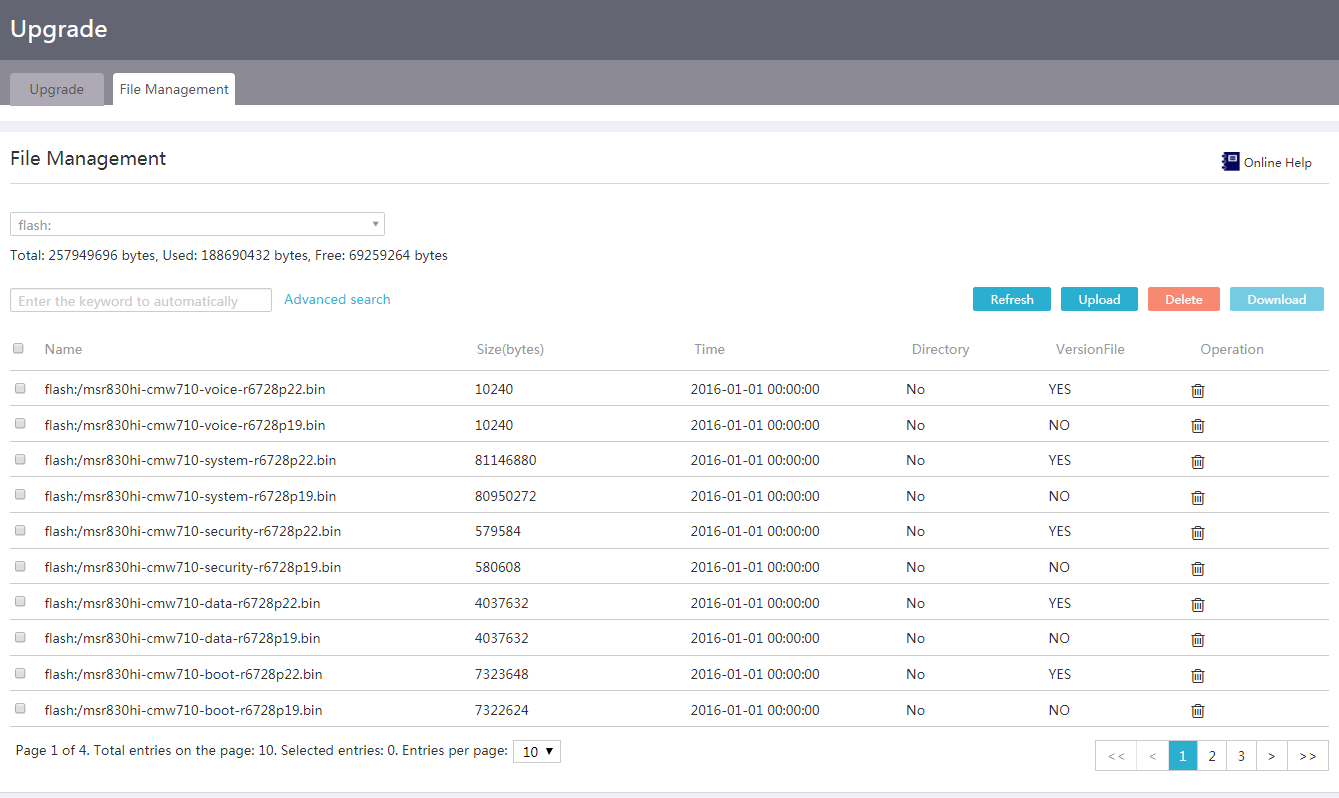
3. Click Upload.
4. Click Select File, and select the file to be uploaded.
5. Click Apply.
Figure 155 Uploading a file
Delete files
Restrictions and guidelines
Do not delete the image files being used by the device. If you delete the files, the device cannot operate correctly.
Procedure
1. From the navigation tree, select System Tool > Upgrade.
2. Click the File System tab.
3. Select the file or files to be deleted.
4. Click Delete.
Figure 156 Deleting files
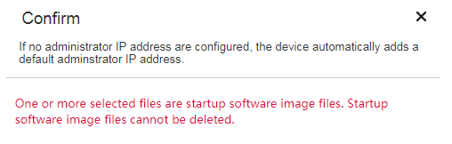
Download files
1. From the navigation tree, select System Tool > Upgrade.
2. Click the File System tab.
3. Select the file or files to be downloaded.
4. Click Download and select the destination path.
License management
About license management
To use a license-based feature on the device, you need to purchase a license key, use it to request an activation file, and install the activation file on the device. To view features that must be licensed, click the Licenses and features tab.
|
|
NOTE: Activation file is also called license file on the Web interface of the device. |
Restrictions and guidelines for license management
Make sure no one else is performing license management tasks while you are managing licenses on the device.
View features that require licenses
1. From the navigation pane, select System Tool > License Management.
2. Click the Licenses and features tab.
3. View the license-based features, licensing status, and license type.
¡ Feature name—Displays the features that must be licensed before being used.
¡ Licensed or Not—Displays the licensing state of the feature.
- N—Not licensed.
- Y—Licensed.
¡ Status—Displays the license type.
- Formal—Purchased license. This state indicates that a valid formal license has been installed.
- Trial—Trial license. This state indicates that a valid trial license has been installed.
- Pre-licensed—Preinstalled license. This state indicates that a valid preinstalled license has been installed.
If the feature is not licensed, this field displays a hyphen (-). To use the feature, you must install a valid license.
Figure 157 Licenses and features
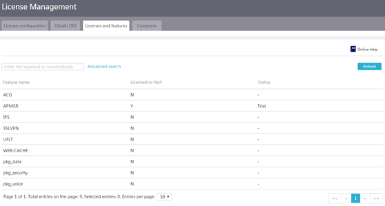
Compress the license storage
About this task
Compress the license storage to delete expired license information. This operation ensures sufficient storage space for installing new licenses.
Restrictions and guidelines
If expired licenses exist on the device, the compression operation will make the DID change. Before performing a compression, make sure all licenses registered with the old DID have been installed. You will be unable to install such licenses after the compression.
Procedure
1. From the navigation pane, select System Tool > License Management.
2. Click the Compress tab.
3. On the page that opens, you can click Compress if the remaining number of allowed activation files is smaller than the number of activation files to be installed.
Remaining number of allowed activation files = Total number of allowed activation files – Number of installed activation files.
4. Click Apply.
Figure 158 Compressing the license storage
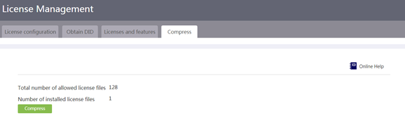
Request an activation file
Restrictions and guidelines
Save the activation file properly and back it up to avoid accidental loss or deletion.
Do not modify the name or content of the activation file to avoid licensing failures.
If you cannot obtain the activation file after filling in the correct information on H3C License Management Platform, contact H3C Support.
Prerequisites
Obtain a license key by purchasing a software license certificate.
Procedure
1. From the navigation pane, select System Tool > License Management.
2. Click the Obtain DID tab.
3. Obtain the device SN and DID.
4. Log in to H3C License Management Platform at https://new-licensing.h3c.com/website/anonymous/navIndex/en-US/activate/input-license to obtain the activation file. For more information about requesting an activation file, see H3C Switches and Routers Licensing Guide.
Figure 159 Obtaining the DID
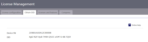
Install a license
1. From the navigation pane, select System Tool > License Management.
2. On the License configuration tab, click Add.
Figure 160 License configuration
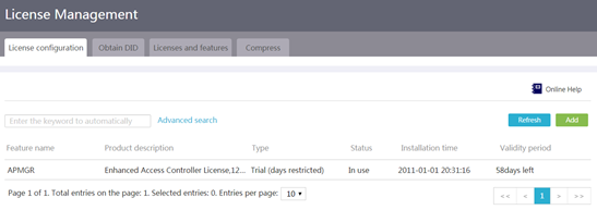
3. In the dialog box that opens, select an activation file, and then click Apply.
Figure 161 Installing a license
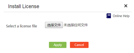
Reboot
Introduction to reboot
Perform this task to reboot the device immediately or at a scheduled time.
Reboot now
Restrictions and guidelines
Rebooting the device will cause service interruption. Perform this operation with caution.
Procedure
1. From the navigation pane, select System Tool > Reboot.
2. On the Reboot now tab, click Reboot Device.
3. In the dialog box that opens, select one of the following options:
¡ Save running configuration before the reboot.
¡ Force reboot the device immediately without performing any software check.
4. Click Apply.
Figure 162 Rebooting the device now
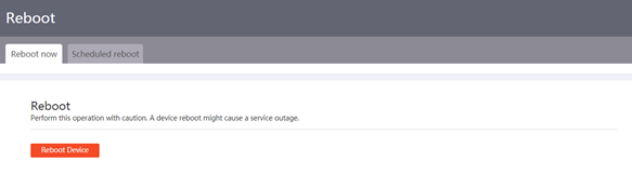
Scheduled reboot
1. From the navigation pane, select System Tool > Reboot.
2. Click the Scheduled reboot tab.
3. In the Scheduled reboot field, select Enable.
4. In the Reboot at field, specify the device reboot time every week.
5. Click Submit. The device will reboot at the scheduled time.
Figure 163 Scheduling the reboot
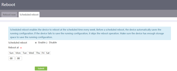
System log
Introduction to system log
During operation, the device generates system log to record the settings configured by the administrator, device state changes, and important events on the device. Based on the system log, you can monitor device performance and troubleshoot network issues.
You can send the system log to a log server for centralized management or view log entries directly on the webpage.
Logs are classified into eight severity levels from 0 through 7 in descending order of severity, as shown in Table 1.
|
Severity value |
Level |
Description |
|
0 |
Emergency |
The system is unusable. For example, the system authorization has expired. |
|
1 |
Alert |
Action must be taken immediately. For example, traffic on an interface exceeds the upper limit. |
|
2 |
Critical |
Critical condition. For example, the device temperature exceeds the upper limit, the power module fails, or the fan tray fails. |
|
3 |
Error |
Error condition. For example, the link state changes. |
|
4 |
Warning |
Warning condition. For example, an interface is disconnected, or the memory resources are used up. |
|
5 |
Notification |
Normal but significant condition. For example, a terminal logs in to the device, or the device reboots. |
|
6 |
Informational |
Informational message. For example, a command or a ping operation is executed. |
|
7 |
Debugging |
Debugging message. |
Send system log to a log server
Prerequisites
Make sure the device and the log server can reach each other.
Procedure
1. From the navigation pane, select System Tool > System Log.
2. On the System Log tab, select Send to a log server, and then enter the IP address or host name of a log server.
3. Click Apply.
Figure 164 Sending system log to a log server
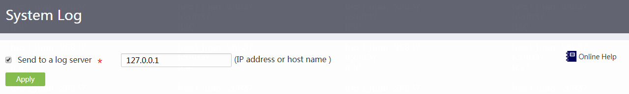
View system log on the webpage
1. From the navigation pane, select System Tool > System Log.
2. On the System Log tab, log entries are listed with time, level, and description information. You can view specific log entries by specifying the search conditions.
3. Click Export to export the log entries to the PC that you have logged in.
Figure 165 Viewing system log
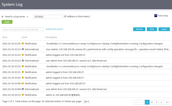
SmartMC
Configuration wizard
Introduction to SmartMC
Smart Management Center (SmartMC) centrally manages and maintains dispersed network devices at network edges. In a SmartMC network, one device acts as the commander to manage the remaining devices that act as members.
On this page, you can set a device role to commander. After you specify the commander, you can access the Intelligent Management, Intelligent O&M, and Visibility pages and use features provided on the pages to manage members uniformly. You cannot access the Configure Wizard page once the commander is set.
Members can join a SmartMC network automatically. To add members manually, access the Visibility > Topology page and click Add. For a member device, you can access the Configuration Wizard page, the Intelligent Management > Roles page, and the Intelligent Management > Disable SmartMC page. To switch the device role from member to commander, access the Configuration Wizard page or the Intelligent Management > Roles page.
Restrictions and guidelines
A SmartMC network has only one commander.
For members to join a SmartMC network automatically, you must first configure the commander and then start members without any settings.
Procedure
1. From the navigation pane, select Configuration Wizard.
2. Click the Management IP address tab.
3. In the Configure management IP address area, enter the IP address of the device VLAN interface 1.
Applying the IP address of VLAN interface 1 indicates that the SmartMC network is created in VLAN 1. If the IP address of VLAN interface 1 has been configured, you can use the address as the management IP address directly.
4. In the Mask length area, specify the management IP address mask length.
Figure 166 Configuring the management IP address
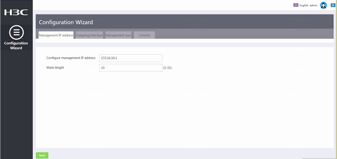
5. Click Next.
You are placed on the Outgoing interface tab.
When the device and VLAN 1 (where the SmartMC network resides) are not in the same network segment, you cannot use the device to access the Web interface of a member directly. To address this issue, configure the commander interface that connects to the device as an outgoing interface, access the Visibility > Typology page, select a member in the topology map, and click Log in to Web Interface for the member.
6. In the Outgoing interface area, specify the interface that connects to the device as the outgoing interface.
Figure 167 Configuring an outgoing interface
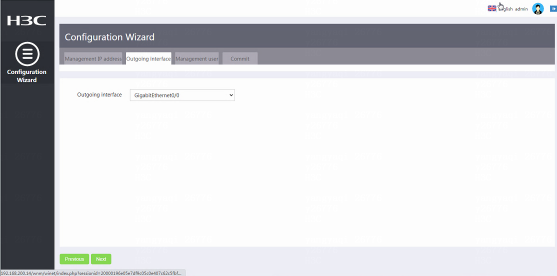
7. Click Next.
You are placed on the Management user page.
The management user is a local user of the commander. If the specified user does not exist, the system will create the user as a local user.
8. In the Username area, enter the local username.
9. In the Password area, enter the password for local user login.
Figure 168 Configuring the management user
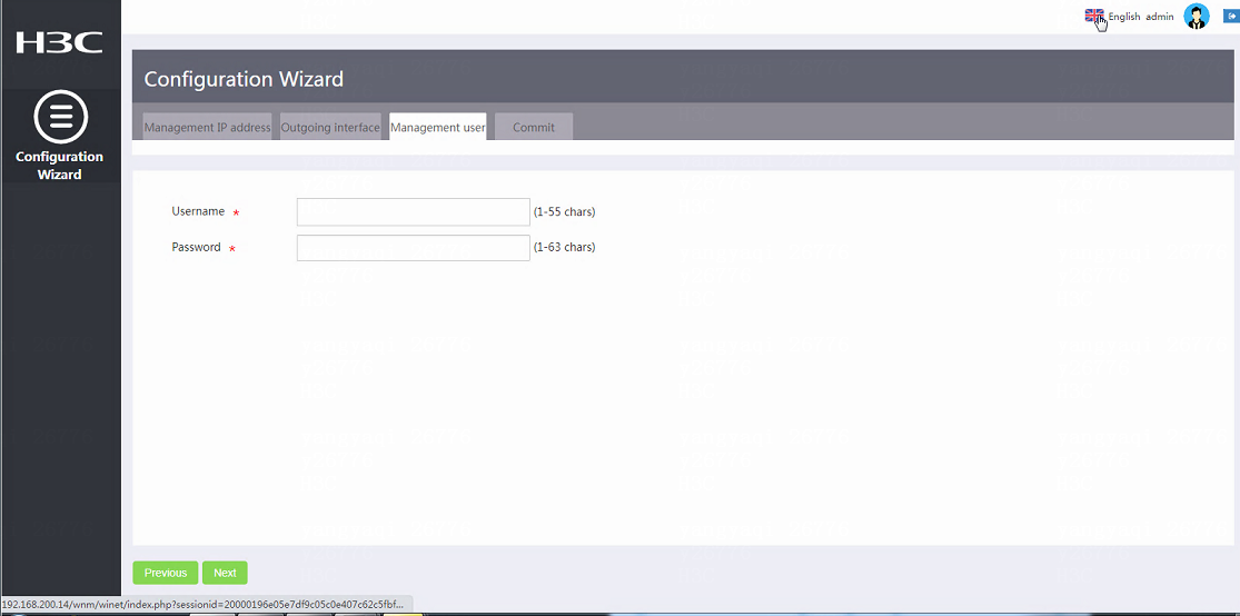
10. Click Next.
You are placed on the Commit page.
11. Verify that the configuration is correct and click Certain.
Figure 169 Finishing the configuration
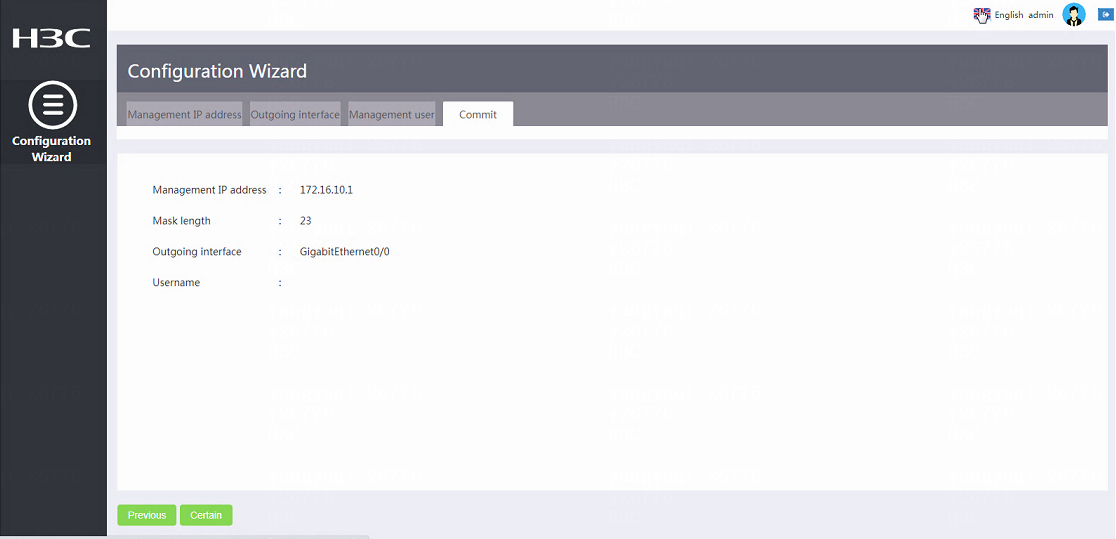
Intelligent management
Configure the device role
Introduction to device role configuration
Perform this task to switch the device role to commander or member.
Restrictions and guidelines
To avoid downloading an incorrect configuration file for the device, delete the backup configuration file for the original commander from the FTP server after you switch the device role from commander to member.
Procedure
1. From the navigation pane, select Intelligent Management.
2. Click the Roles tab.
3. In the Specify device role area, select Commander or Member.
4. Click Certain.
Figure 170 Specifying the device role
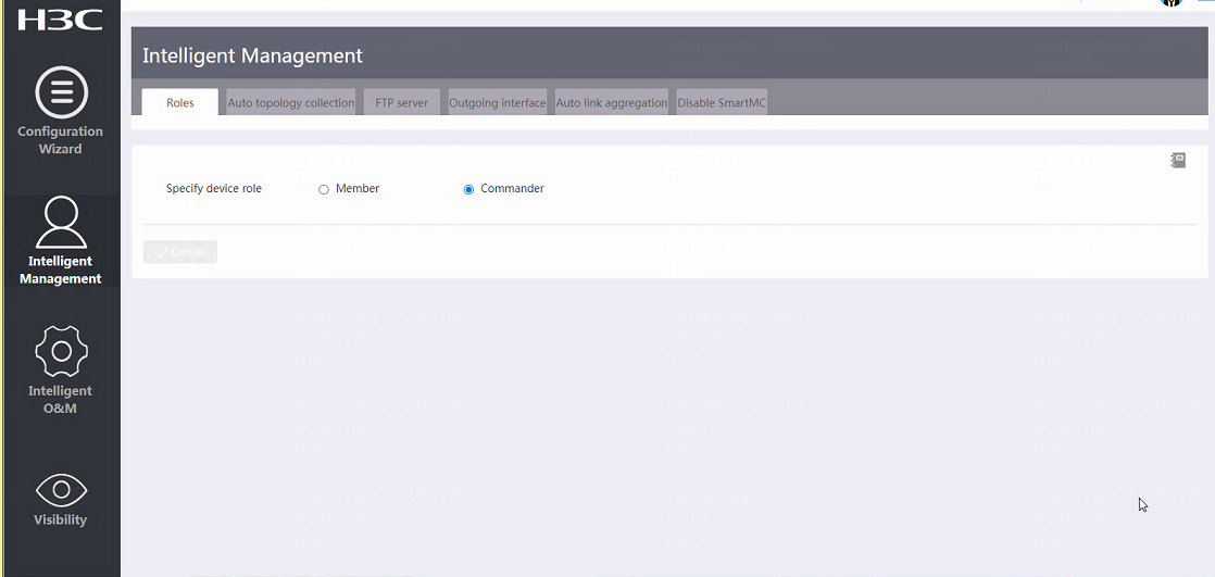
Configure an outgoing interface
Introduction to outgoing interface configuration
An outgoing interface is a layer 3 Ethernet interface on the commander. It is used for the device to access the Web interface of a member directly.
As shown in Figure 171, the host connects to the commander through Interface and the network segment is 192.168.56.0/24. The SmartMC network is in VLAN 1 that resides in network segment 192.168.2.0/24. In this case, the host can access the Web interface of the commander but cannot access that of any member.
To address the issue, configure Interface as an outgoing interface of the SmartMC network. After the configuration, to access the Web interface of a member, you can access the interface of the commander, select Visibility > Typology, select the member in the typology map, and click Log in to Web interface. In this case, the commander mirrors the member address to a new address in Outgoing_IP_address:Port_number format and you can use the new address to visit the Web interface of the member.
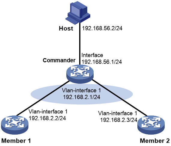
Restrictions and guidelines
The SmartMC network resides in VLAN 1 and you cannot configure VLAN-interface 1 as the outgoing interface for the SmartMC network.
Procedure
1. From the navigation pane, select Intelligent Management.
2. Click the Outgoing interface tab.
3. To configure an interface as an outgoing interface, click the ![]() icon in the Operation column of the interface from the list.
icon in the Operation column of the interface from the list.
4. To delete an interface, click the ![]() icon in the Operation column of the interface from the list.
icon in the Operation column of the interface from the list.
Figure 172 Configuring an outgoing interface
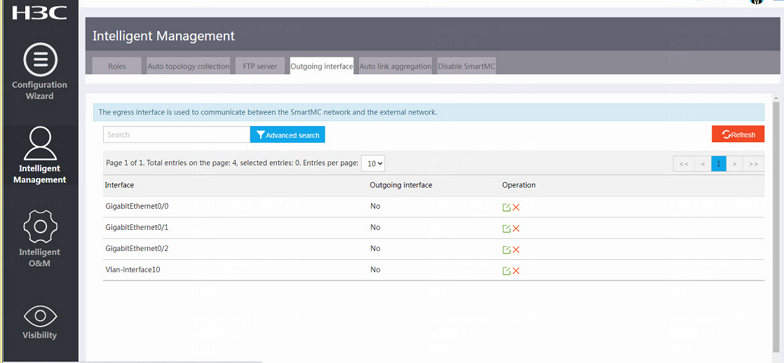
Intelligent O&M
Upgrade devices
Introduction to device upgrade
Perform this task to upgrade startup software and the configuration file of members from the commander.
When the members are downloading upgrade files from the FTP server, to cancel the downloading, click Cancel Downloading.
When an upgrade is in progress, to cancel the upgrade, click Cancel Upgrade.
Restrictions and guidelines
Before the upgrade, make sure you have configured the FTP server. You can access the Intelligent Management > FTP server page to configure the settings.
Before the upgrade, make sure the upgrade files have been saved on the FTP server. During the upgrade, members will download the files from the FTP server automatically.
Configure upgrade files
1. From the navigation pane, select Intelligent O&M.
2. Click the Upgrade device tab.
3. To configure the upgrade file, click the ![]() icon in the Operation column of a device from the list.
icon in the Operation column of a device from the list.
4. On the page that opens, specify the upgrade file type.
¡ If you select the IPE file, enter the IPE file name.
¡ If you select the BIN file, enter the boot package name and the system package name.
¡ If you select the configuration file, enter the configuration file name.
5. Repeat the previous steps to configure upgrade files for all devices to be upgraded.
Upgrade devices
1. From the navigation pane, select Intelligent O&M.
2. Click the Upgrade device tab.
3. Select devices to be upgraded from the list.
4. Click Upgrade.
5. On the page that opens, specify an object to upgrade and the upgrade time.
¡ If you select to delay the upgrade, specify the delay time.
¡ If you select to start the upgrade at a scheduled time, specify the upgrade time.
6. Click Certain.
Cancel the upgrade
1. From the navigation pane, select Intelligent O&M.
2. Click the Upgrade device tab.
3. Select devices of which the upgrade is to be canceled.
4. Click Cancel upgrade.
Deploy VLAN in one step
Introduction to VLAN deployment in one step
Perform this task to assign all ports on a member that meet the following criteria into a specified VLAN:
· The port is not connected to other members or the commander.
· The port is an access port.
Restrictions and guidelines
· Access ports that are connected to offline members cannot be assigned to the specified VLAN.
· The VLAN creation fails for a member if one or more access ports cannot be assigned to the VLAN. If the VLAN creation fails, the VLAN memberships for the access ports are restored to the state before the VLAN was created.
· The failure to create a VLAN for a member does not affect the VLAN creation for other members.
Procedure
1. From the navigation pane, select Intelligent O&M.
2. Click the Deploy VLAN in one step tab.
3. In Please select operation object area, select Members or SmartMC groups.
4. Select members or SmartMC groups from the list to deploy and click Deploy VLAN in one step.
5. On the page that opens, enter the VLAN ID.
6. Click Certain.
7. To view the configuration result, click View deployment result.
Intelligent port identification
Introduction to intelligent port identification
Restrictions and guidelines
· To avoid configuration errors, make sure all commands in the batch file can be executed in interface view.
· The batch file can contain a maximum of 8190 characters.
· Make sure the file name is correct when specifying the batch file because the system does not verify whether the file name is correct. After specifying the batch file, do not delete the file or rename the file.
· Before configuration deployment, the system restores the port configurations to the default settings.
· When the AP or IP phone disconnects from the port, the configurations on the port remain unchanged.
Set port identification
1. From the navigation pane, select Intelligent O&M.
2. Click the Intelligent port identification tab.
3. Click Create and create a batch configuration file for the port. After the creation, the system will refresh the file list automatically. If the batch file already exists, proceed to next step directly.
4. Select a batch file from the list.
5. Click Set port identification.
6. In the Accessing device area, select AP or IP phone.
7. Click Certain.
Figure 173 Setting port identification
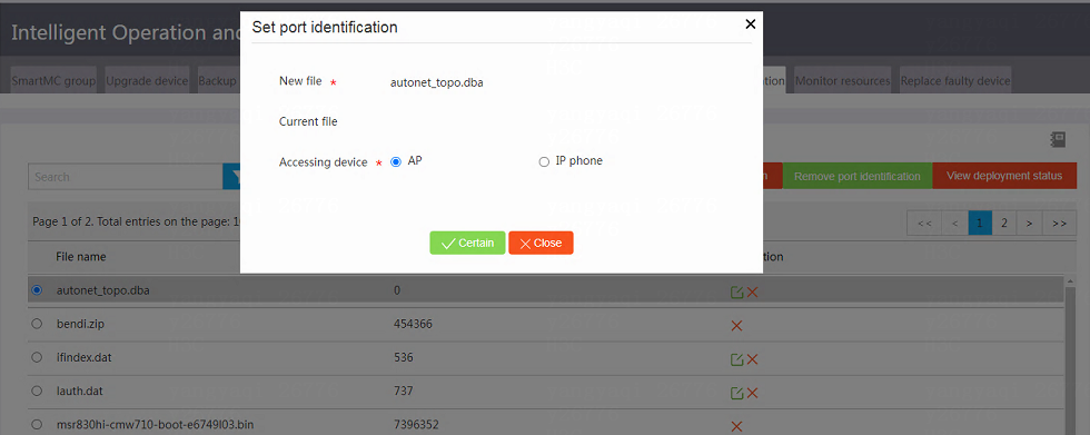
Remove port identification
1. From the navigation pane, select Intelligent O&M.
2. Click the Intelligent port identification tab.
3. Click Remove port identification.
4. On the page than opens, in the Accessing device area, select AP or IP phone.
5. Click Certain.
Figure 174 Removing port identification
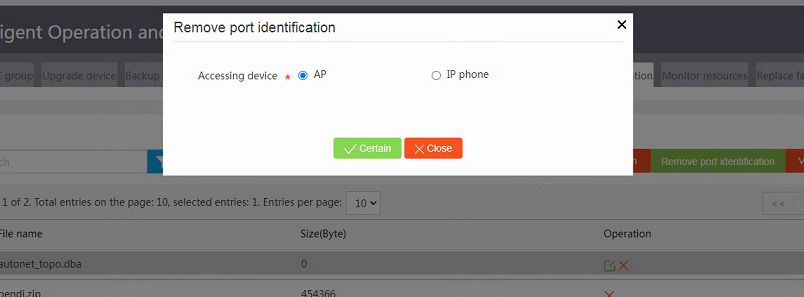
View deployment status
1. From the navigation pane, select Intelligent O&M.
2. Click the Intelligent port identification tab.
3. Click View deployment status.
4. On the page than opens, in the Deployment method area, select Manual deployment or Auto deployment.
5. If you select Auto deployment, in the Accessing device, select AP or IP phone.
Figure 175 Viewing the port configuration state
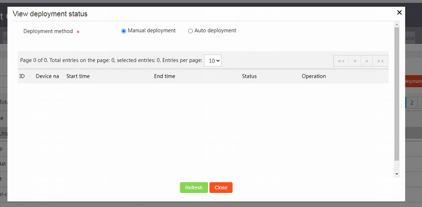
Replace a faulty device
Introduction to faulty device replacement
You can use automatic or manual replacement to replace a faulty member.
· To perform a manual replacement, the device type must be the same for the new member and the faulty member.
· To perform an automatic replacement, the following requirements must be met:
¡ The device type is the same for the new member and the faulty member.
¡ The LLDP information is the same for the new member and the faulty member.
¡ The LLDP information obtained for the new member is the same for consecutive three times within an hour.
The commander instructs the new member to download the configuration file of the faulty member from the FTP server. After downloading the configuration file, the new member runs the configuration file to complete the replacement.
Restrictions and guidelines
· When one or more devices are faulty, the commander cannot perform an automatic replacement and manual replacements are required.
· To avoid stack split of a new member, make sure the stack configuration and physical connection are the same for the new member and the faulty member when replacing a stack device.
Replace a faulty device automatically
1. From the navigation pane, select Intelligent O&M.
2. Click the Replace faulty device tab.
3. Click Enable auto replacement.
4. Install the new member at the location where the faulty member was installed and start the device.
Figure 176 Replacing a faulty member automatically
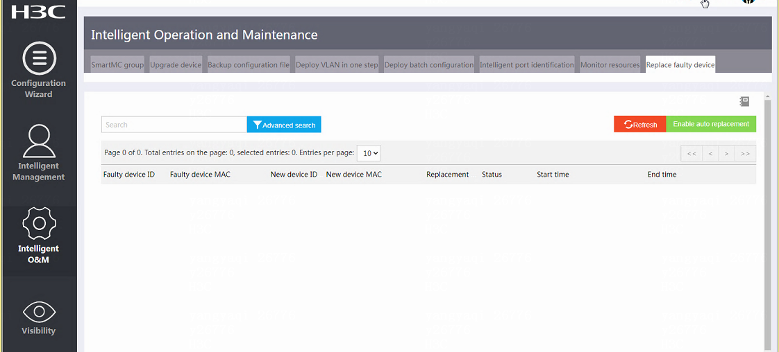
Replace a faulty member manually
1. From the navigation pane, select Intelligent O&M.
2. Click the Replace faulty device tab.
3. Install the new member at the location where the faulty member was installed and start the device.
4. From the navigation pane, click Visibility.
5. Click the Typology tab.
6. Click Manual replacement.
7. On the page that opens, specify the device model, the faulty device, and the new device.
8. Click Certain.
Figure 177 Replacing a faulty member manually
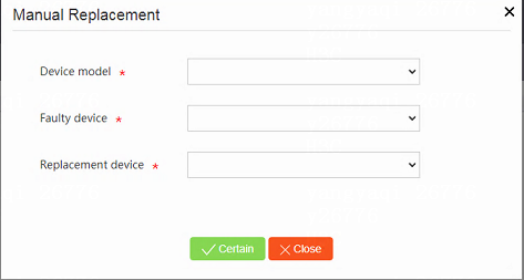
Visibility
Save typology
Introduction to typology saving
The system draws the SmartMC network topology automatically. After all devices join the network, the administrators can view the topology from the Web interface, drag member device icons to adjust their locations, and save the adjusted topology to the local PC. The system will display the saved topology at subsequent logins from the same PC until the network changes.
· ![]() indicates the
commander.
indicates the
commander.
· ![]() indicates members
that are operating correctly.
indicates members
that are operating correctly.
· ![]() indicates members added to the network after the topology saving.
indicates members added to the network after the topology saving.
· ![]() indicates members going offline after the topology saving.
indicates members going offline after the topology saving.
· ![]() indicates
APs in the SmartMC network.
indicates
APs in the SmartMC network.
Restrictions and guidelines
· The typology map is saved in the current browser and the saved typology does not take effect if you change the browser.
· After the typology saving, if the SmartMC network changes, for example, some members added or removed, the system draws a new typology automatically. The saved typology no longer takes effect.
Procedure
1. From the navigation pane, click Visibility.
2. Click the Typology tab.
3. Click Collect typology. The system collects device, neighbor, and port information in the SmartMC network
4. Click Manual refresh. The system refreshes the current typology map based on the neighbor and device information.
5. Drag member icons to optimize the SmartMC network typology.
6. Click Save typology.
Figure 178 Refreshing the typology manually
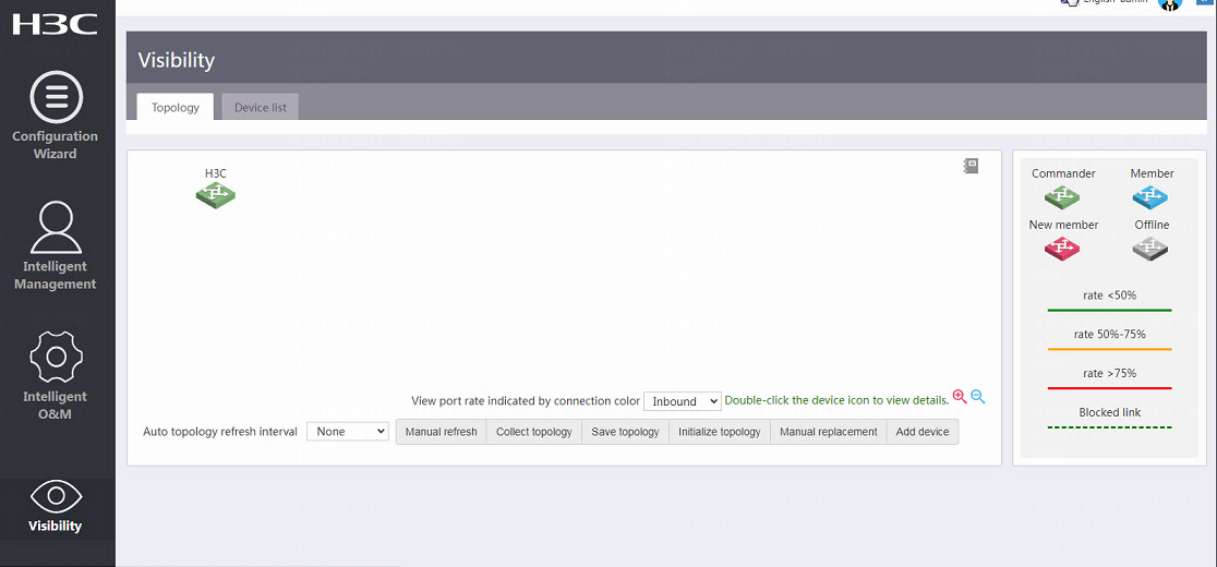
Initialize typology
Introduction to typology initialization
Perform this task to remove offline devices in the SmartMC network and restore the original member state.
Procedure
1. From the navigation pane, click Visibility.
2. Click the Typology tab.
3. Click Initialize typology.
Figure 179 Initializing typology
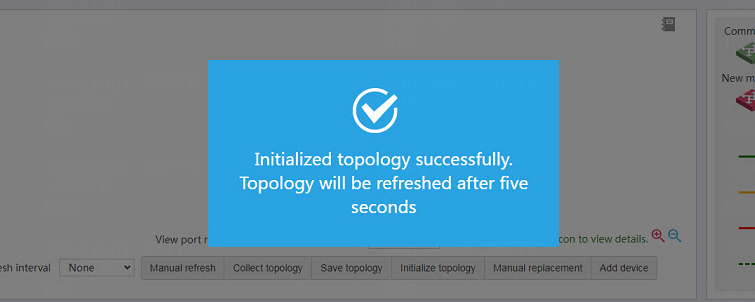
Replace configuration manually
Introduction to configuration replacement for a faulty device
After the faulty member is physically replaced, perform this task to trigger a configuration replacement. The new member will download the configuration file of the faulty member from the FTP server and run the file to complete the replacement.
Restrictions and guidelines
· Make sure the new member for replacement and the faulty member have the same device model and IRF member ID.
· Before you replace a faulty member, install the new member at the location where the faulty member was installed, and connect all cables to the new member.
Procedure
1. From the navigation pane, click Visibility.
2. Click the Typology tab.
3. Click Manual replacement.
4. On the page that opens, specify the device model, the faulty device, and the new device.
5. Click Certain.
Figure 180 Replacing the configuration manually

Add a device
Introduction to device adding
Perform this task to add devices to the SmartMC network manually. The system displays the number of devices that are not available for the adding on the upper right corner of the Add Device button.
Restrictions and guidelines
Before adding a device to the SmartMC network manually, make sure you configure the following settings:
· Enable HTTP and HTTPS services.
· Enable Telnet service.
· Enable NETCONF over SOAP based on HTTP.
· Enable the LLDP feature globally.
· Configure the local user admin whose password is admin, service type is Telnet, HTTP, and HTTPS, and RBAC role is network-admin.
· Specify the VTY line authentication method scheme.
· Configure the device to support SNMPv2c and specify SNMP community name public for read-only operations.
Procedure
1. From the navigation pane, select Visibility.
2. Click the Typology tab.
3. Click Add device.
4. On the page that opens, specify the IP address, username, and password.
5. Click Certain.
Figure 181 Adding a device
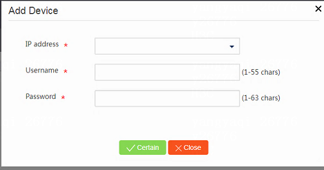
Member related features
Configure ports
1. From the navigation pane, select Visibility.
2. Click the Typology tab.
3. Click the target device icon.
4. On the device pane, select interfaces.
5. Click Configure ports.
6. On the page that opens, select the batch configuration file.
7. Click Certain. The system will issue the settings in the file to the corresponding interfaces.
8. From the navigation pane, select Intelligent O&M.
9. Click the Intelligent port identification tab.
10. Click View deployment status to view the interface status.
Rename a device
1. From the navigation pane, select Visibility.
2. Click the Typology tab.
3. Click the target device icon.
4. Click Rename device.
5. On the page that opens, enter the device name.
6. Click Certain.
Log in to the Web interface
Introduction to Web interface login
Perform this task to log in to the management Web interface of a member.
Procedure
1. From the navigation pane, select Visibility.
2. Click the Typology tab.
3. Click the target member icon.
4. Click Log in to Web interface.
5. On the page that opens, enter the member username and password.
Figure 182 Logging in to the Web interface

Reboot a device
Introduction to device reboot
Perform this task to restart a member. Supported restart methods include:
· Save the configuration and restart.
· Force restart.
· Restart with factory default settings.
Restrictions and guidelines
To avoid service interruptions, restart devices with caution.
For devices that support automatic configuration, the devices will start automatic configuration after restart with factory default settings.
Procedure
1. From the navigation pane, select Visibility.
2. Click the Typology tab.
3. Click the target member icon.
4. Click Reboot device.
5. On the page that opens, specify a restart method.
6. Click Certain.
Member logs
Introduction to member logs
Perform this task to view cache logs and restart logs for members and AP restart logs.
Restrictions and guidelines
The commander can store a maximum of 10 restart logs for each member.
Procedure
1. From the navigation pane, select Visibility.
2. Click the Typology tab.
3. Click the target member icon.
4. Click Member logs.
Monitoring information
Introduction to monitoring information
Perform this task to view monitoring information for members, such as CPU usage, memory usage, temperature information, and packet loss information.
Procedure
1. From the navigation pane, select Visibility.
2. Click the Typology tab.
3. Click the target member icon.
4. Click Monitoring information.
Device list
Introduction to device list
The device list displays basic information
for the commander and members. To view detailed information of a device, click
the ![]() icon in the Operation column of the device. You can view and
configure custom device types.
icon in the Operation column of the device. You can view and
configure custom device types.
Configure a custom device type
1. From the navigation pane, select Visibility.
2. Click the Device list tab.
3. Select a target device, click the ![]() icon in the Operation column of the device.
icon in the Operation column of the device.
4. On the device details page that opens, search for the device SYSOID value and copy the value.
5. Click Close to close the page.
6. Click Customize device type.
7. On the page that opens, paste the SYSOID value and specify the device type.
8. Click Certain.
Figure 183 Customizing device type
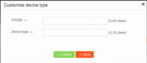
View customized device types
1. From the navigation pane, select Visibility.
2. Click the Device list tab.
3. Click View customized device type.
Figure 184 Viewing customized device types