- Table of Contents
-
- 06-IP Multicast Configuration Guide
- 00-Preface
- 01-Multicast overview
- 02-IGMP snooping configuration
- 03-PIM snooping configuration
- 04-Multicast VLAN configuration
- 05-Multicast routing and forwarding configuration
- 06-IGMP configuration
- 07-PIM configuration
- 08-MSDP configuration
- 09-Multicast VPN configuration
- 10-MLD snooping configuration
- 11-IPv6 multicast VLAN configuration
- 12-MLD configuration
- 13-IPv6 multicast routing and forwarding configuration
- 14-IPv6 PIM snooping configuration
- 15-IPv6 PIM configuration
- Related Documents
-
| Title | Size | Download |
|---|---|---|
| 09-Multicast VPN configuration | 943.16 KB |
Basic concepts in MDT-based MVPN
MDT-based MVPN inter-AS option A
MDT-based MVPN inter-AS option B
MDT-based MVPN inter-AS option C
Basic concepts in RSVP-TE-based MVPN
Inclusive tunnel establishment
Selective tunnel establishment and tunnel switchover
Software version compatibility with M6VPE
MDT-based MVPN tasks at a glance
RSVP-TE-based MVPN tasks at a glance
Prerequisites for configuring MDT-based MVPN
Enabling IP multicast routing for a VPN instance
Creating an MDT-based MVPN instance
Creating an MVPN address family
Specifying the MVPN source interface
Configuring MDT switchover parameters
Configuring the RPF vector feature
Enabling data-group reuse logging
Setting the DSCP value for outgoing data-group switchover packets
Configuring BGP MDT peers or peer groups
Configuring a BGP MDT route reflector
Configuring BGP optimal route selection delay
Configuring RSVP-TE-based MVPN
Prerequisites for configuring RSVP-TE-based MVPN
Enabling IP multicast routing for a VPN instance
Configuring BGP IPv4 MVPN route exchange
Adding extended community attributes to routes sent to BGP IPv4 MVPN neighbors
Creating an RSVP-TE-based MVPN instance
Creating an MVPN IPv4 address family
Specifying the MVPN source interface
Enabling inclusive tunnel creation
Enabling selective tunnel creation
Setting the tunnel switchover delay
Display and maintenance commands for multicast VPN
Multicast VPN configuration examples
Example: Configuring intra-AS MDT-based MVPN
Example: Configuring intra-AS RSVP-TE-based MVPN
Example: Configuring intra-AS M6VPE
Example: Configuring MDT-based MVPN inter-AS option B
Example: Configuring MDT-based MVPN inter-AS option C
Troubleshooting MDT-based MVPN
A default-MDT cannot be established
Configuring multicast VPN
About multicast VPN
Typical network diagram
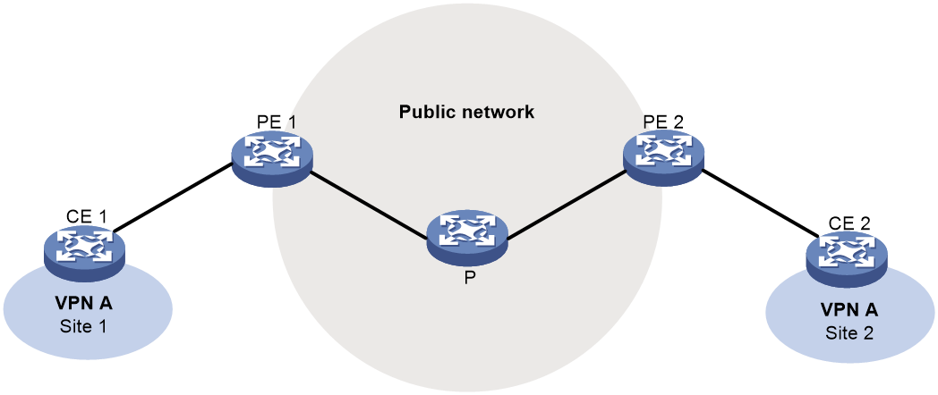
As shown in Figure 1, VPN A contains Site 1 and Site 3, and VPN B contains Site 2 and Site 4.
Figure 1 Typical network diagram for multicast VPN
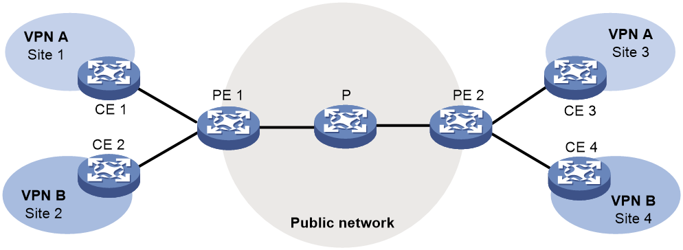
VPN multicast traffic between the PEs and the CEs is transmitted on a per-VPN-instance basis. The public network multicast traffic between the PEs and the P device is transmitted through the public network. Multicast VPN provides independent multicast services for the public network, VPN A, and VPN B.
For more information about CEs, PEs and Ps, see MPLS Configuration Guide.
MVPN scheme
MVPN is used to implement multicast VPN. MVPN only requires the PEs to support multiple VPN instances and the public network provided by the service provider to support multicast. There is no need to upgrade CEs and Ps or change their PIM configurations. The MVPN solution is transparent to CEs and Ps.
An MVPN can be MDT based or RSVP-TE based.
Basic concepts in MDT-based MVPN
This section introduces the following basic concepts in MDT-based MVPN:
· MVPN—An MVPN logically defines the transmission boundary of the multicast traffic of a VPN over the public network. It also physically identifies all the PEs that support that VPN instance on the public network. Different VPN instances correspond to different MVPNs.
· Multicast distribution tree (MDT)—An MDT is a multicast distribution tree constructed by all PEs in the same VPN. MDT includes default-MDT and data-MDT.
· Multicast tunnel (MT)—An MT is a tunnel that interconnects all PEs in an MVPN. The local PE encapsulates a VPN multicast packet into a public network multicast packet and forwards it through the MT over the public network. The remote PE decapsulates the public network multicast packet to get the original VPN multicast packet.
· Multicast tunnel interface (MTI)—An MTI is the entrance or exit of an MT, equivalent to an entrance or exit of an MVPN. MTIs are automatically created when the MVPN for the VPN instance is created. PEs use the MTI to access the MT. The local PE sends VPN data out of the MTI. The remote PEs receive the private data from their MTIs. An MTI runs the same PIM mode as the VPN instance to which the MTI belongs. PIM is enabled on MTIs when a minimum of one interface in the VPN instance is enabled with PIM. When PIM is disabled on all interfaces in the VPN instance, PIM is also disabled on MTIs.
· Default-group—A default-group is a unique multicast address assigned to each MVPN on the public network. It is the unique identifier of an MVPN on the public network and helps build the default-MDT for an MVPN on the public network. A PE encapsulates a VPN multicast packet (a multicast protocol packet or a multicast data packet) into a public network multicast packet. The default-group address is used as the public network multicast group.
· Default-MDT—A default-MDT uses a default-group address as its group address. In a VPN, the default-MDT is uniquely identified by the default-group. A default-MDT is automatically created after the default-group is specified and will always exist on the public network, regardless of the presence of any multicast services on the public network or the VPN.
· Data-group—An MVPN is assigned a unique data-group for MDT switchover. The ingress PE selects a least used address from the data-group range to encapsulate the VPN multicast packets when the multicast traffic of the VPN arrives at the PE. Other PEs are notified to use the address to forward the multicast traffic for that VPN. This initiates the switchover to the data-MDT.
· Data-MDT—A data-MDT is an MDT that uses a data-group as it group address. At MDT switchover, PEs with downstream receivers join a data-group to build a data-MDT. The ingress PE forwards the encapsulated VPN multicast traffic along the data-MDT over the public network.
How MDT-based MVPN works
For a VPN instance, multicast data transmission on the public network is transparent. The VPN data is exchanged between the MTIs of the local PE and the remote PE. This implements the seamless transmission of the VPN data over the public network. However, the multicast data transmission process (the MDT transmission process) over the public network is very complicated.
|
|
NOTE: The following types of PIM neighboring relationships exist in MVPN: · PE-P PIM neighboring relationship—Established between the public network interface on a PE and the peer interface on the P device over the link. · PE-PE PIM neighboring relationship—Established between PEs that are in the same VPN instance after they receive the PIM hello packets. · PE-CE PIM neighboring relationship—Established between a PE interface that is bound with the VPN instance and the peer interface on the CE over the link. |
Default-MDT establishment
The multicast routing protocol running on the public network can be PIM-DM, PIM-SM, BIDIR-PIM, or PIM-SSM. The process of creating a default-MDT is different in these PIM modes.
Default-MDT establishment in a PIM-DM network
Figure 2 Default-MDT establishment in a PIM-DM network

As shown in Figure 2, PIM-DM is enabled on the network, and all the PEs support VPN instance A. The process of establishing a default-MDT is as follows:
1. To establish PIM neighboring relationships with PE 2 and PE 3 through the MTI for VPN instance A, PE 1 does the following:
a. Encapsulates the PIM protocol packet of the private network into a public network multicast data packet. PE 1 does this by specifying the source address as the IP address of the MVPN source interface and the multicast group address as the default-group address.
b. Sends the multicast data packet to the public network.
For other PEs that support VPN instance A as default-group members, PE 1 of VPN instance A initiates a flood-prune process in the entire public network. A (11.1.1.1, 239.1.1.1) state entry is created on each device along the path on the public network. This forms an SPT with PE 1 as the root, and PE 2 and PE 3 as leaves.
2. At the same time, PE 2 and PE 3 separately initiate a similar flood-prune process.
Finally, three independent SPTs are established in the MVPN, constituting the default-MDT in the PIM-DM network.
Default-MDT establishment in a PIM-SM network
Figure 3 Default-MDT establishment in a PIM-SM network

As shown in Figure 3, PIM-SM is enabled on the network, and all the PEs support VPN instance A. The process of establishing a default-MDT is as follows:
1. PE 1 initiates a join to the public network RP by specifying the multicast group address as the default-group address in the join message. A (*, 239.1.1.1) state entry is created on each device along the path on the public network.
2. At the same time, PE 2 and PE 3 separately initiate a similar join process.
Finally, an RPT is established in the MVPN, with the public network RP as the root and PE 1, PE 2, and PE 3 as leaves.
3. To establish PIM neighboring relationships with PE 2 and PE 3 through the MTI for VPN instance A, PE 1 does the following:
a. Encapsulates the PIM protocol packet of the private network into a public network multicast data packet. PE 1 does this by specifying the source address as the IP address of the MVPN source interface and the multicast group address as the default-group address.
b. Sends the multicast data packet to the public network.
The public network interface of PE 1 registers the multicast source with the public network RP, and the public network RP initiates a join to PE 1. A (11.1.1.1, 239.1.1.1) state entry is created on each device along the path on the public network.
4. At the same time, PE 2 and PE 3 separately initiate a similar register process.
Finally, three SPTs between the PEs and the RP are established in the MVPN.
In the PIM-SM network, the RPT, or the (*, 239.1.1.1) tree, and the three independent SPTs constitute the default-MDT.
Default-MDT establishment in a BIDIR-PIM network
Figure 4 Default-MDT establishment in a BIDIR-PIM network
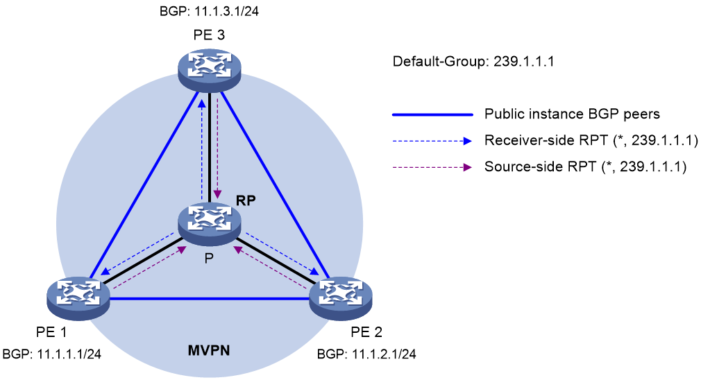
As shown in Figure 4, BIDIR-PIM runs on the network, and all the PEs support VPN instance A. The process of establishing a default-MDT is as follows:
1. PE 1 initiates a join to the public network RP by specifying the multicast group address as the default-group address in the join message. A (*, 239.1.1.1) state entry is created on each device along the path on the public network.
At the same time, PE 2 and PE 3 separately initiate a similar join process. Finally, a receiver-side RPT is established in the MVPN, with the public network RP as the root and PE 1, PE 2, and PE 3 as leaves.
2. PE 1 sends a multicast packet with the default-group address as the multicast group address. The DF of each network segment on the public network forwards the multicast packet to the RP. Each device on the path creates a (*, 239.1.1.1) state entry.
At the same time, PE 2 and PE 3 separately initiate a similar process. Finally, three source-side RPTs are established in the MVPN, with PE 1, PE 2, and PE 3 as the roots and as the public network RP as the leave.
3. The receiver-side RPT and the three source-side RPTs constitute the default-MDT in the BIDIR-PIM network.
Default-MDT establishment in a PIM-SSM network
Figure 5 Default-MDT establishment in a PIM-SSM network
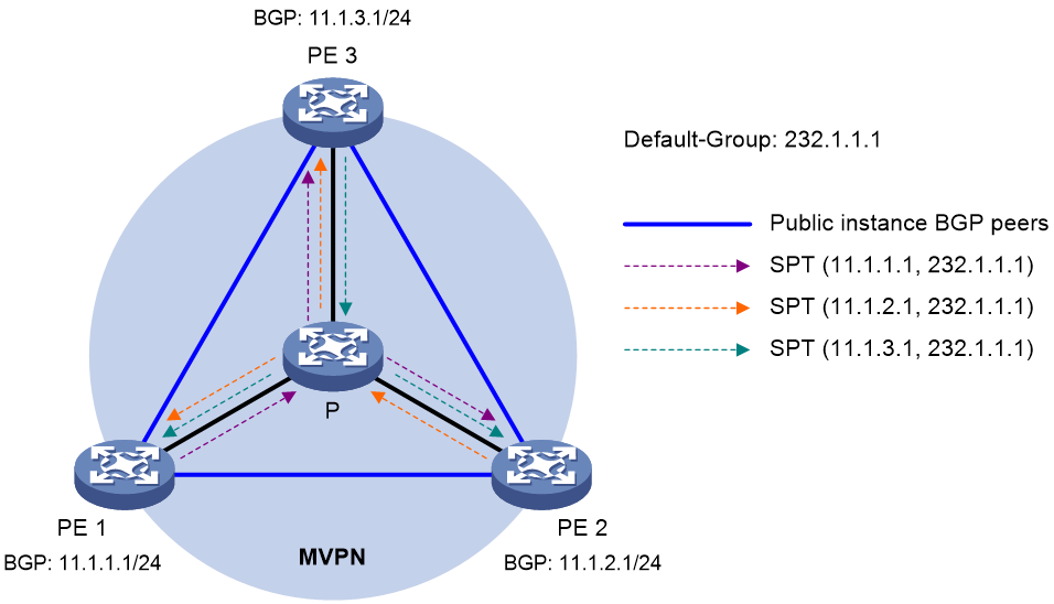
As shown in Figure 5, PIM-SSM runs on the network, and all the PEs support VPN instance A. The process of establishing a default-MDT is as follows:
1. PE 1, PE 2, and PE 3 exchange MDT route information (including BGP interface address and the default-group address) through BGP.
2. PE 1 sends a subscribe message to PE 2 and PE 3. Each device on the public network creates an (S, G) entry. An SPT is established in the MVPN with PE 1 as the root and PE 2 and PE 3 as the leaves.
At the same time, PE 2 and PE 3 separately initiate a similar process, and establish an SPT with itself as the root and the other PEs as the leaves.
3. The three independent SPTs constitute the default-MDT in the PIM-SSM network.
In PIM-SSM, the term "subscribe message" refers to a join message.
Default-MDT characteristics
No matter which PIM mode is running on the public network, the default-MDT has the following characteristics:
· All PEs that support the same VPN instance join the default-MDT.
Default-MDT-based delivery
After the default-MDT is established, the multicast source forwards the VPN multicast data to the receivers in each site along the default-MDT. The VPN multicast packets are encapsulated into public network multicast packets on the local PE, and transmitted along the default-MDT. Then, they are decapsulated on the remote PE and transmitted in that VPN site.
VPN multicast data packets are forwarded across the public network differently in the following circumstances:
· If PIM-DM or PIM-SSM is running in the VPN, the multicast source forwards multicast data packets to the receivers along the VPN SPT across the public network.
· When PIM-SM is running in the VPN:
¡ Before the RPT-to-SPT switchover, if the multicast source and the VPN RP are in different sites, the VPN multicast data packets travel to the VPN RP along the VPN SPT across the public network. If the VPN RP and the receivers are in different sites, the VPN multicast data packets travel to the receivers along the VPN RPT over the public network.
¡ After the RPT-to-SPT switchover, if the multicast source and the receivers are in different sites, the VPN multicast data packets travel to the receivers along the VPN SPT across the public network.
· When BIDIR-PIM is running in the VPN, if the multicast source and the VPN RP are in different sites, the multicast source sends multicast data to the VPN RP across the public network along the source-side RPT. If the VPN RP and the receivers are in different sites, the multicast data packets travel to the receivers across the public network along the receiver-side RPT.
For more information about RPT-to-SPT switchover, see "Configuring PIM."
The following example explains how multicast data packets are delivered based on the default-MDT when PIM-DM is running in both the public network and the VPN network.
As shown in Figure 6:
· PIM-DM is running in both the public network and the VPN sites.
· Receiver of the VPN multicast group G (225.1.1.1) in Site 2 is attached to CE 2.
· Source in Site 1 sends multicast data to multicast group (G).
· The default-group address used to forward public network multicast data is 239.1.1.1.
Figure 6 Multicast data packet delivery
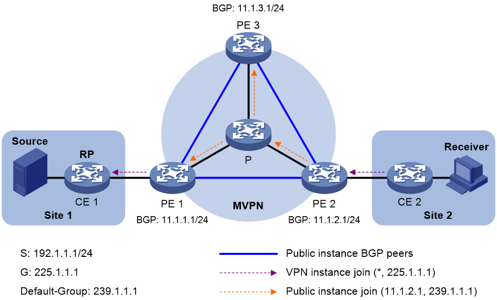
A VPN multicast data packet is delivered across the public network as follows:
1. Source sends a VPN multicast data packet (192.1.1.1, 225.1.1.1) to CE 1.
2. CE 1 forwards the VPN multicast data packet along an SPT to PE 1, and the VPN instance on PE 1 examines the MVRF.
If the outgoing interface list of the forwarding entry contains an MTI, PE 1 processes the VPN multicast data packet as described in step 3. The VPN instance on PE 1 considers the VPN multicast data packet to have been sent out of the MTI, because step 3 is transparent to it.
3. PE 1 encapsulates the VPN multicast data packet into a public network multicast packet (11.1.2.1, 239.1.1.1) by using the GRE method. The source IP address of the packet is the MVPN source interface 11.1.1.1, and the destination address is the default-group address 239.1.1.1. PE 1 then forwards it to the public network.
4. The default-MDT forwards the multicast data packet (11.1.2.1, 239.1.1.1) to the public network instance on all the PEs. After receiving this packet, every PE decapsulates it to get the original VPN multicast data packet, and passes it to the corresponding VPN instance. If a PE has a downstream interface for an SPT, it forwards the VPN multicast packet down the SPT. Otherwise, it discards the packet.
By now, the process of transmitting a VPN multicast data packet across the public network is completed.
MDT switchover
Switching from default-MDT to data-MDT
When a multicast packet of a VPN is transmitted through the default-MDT on the public network, the packet is forwarded to all PEs that support that VPN instance. This occurs whether or not any active receivers exist in the attached sites. When the VPN multicast traffic is high, multicast data might get flooded on the public network. This increases the bandwidth use and brings extra burden on the PEs.
To optimize multicast transmission of large VPN multicast traffic that enters the public network, the MDT-based MVPN solution introduces a dedicated data-MDT. The data-MDT is built between the PEs that connect VPN multicast receivers and multicast sources. When specific network criteria are met, a switchover from the default-MDT to the data-MDT occurs to forward VPN multicast traffic to receivers.
The process of default-MDT to data-MDT switchover is as follows:
1. The source-side PE (PE 1, for example) starts a data-delay timer when receiving the first multicast VPN packet that matches the switchover criterion.
2. When the data-delay timer expires, PE 1 sends an MDT switchover message to all the other PE devices down the default-MDT. This message contains the multicast source address, the multicast group address, and the least-used data-group address in the data-group range.
3. Each PE that receives this message examines whether it interfaces with a VPN that has receivers of that VPN multicast stream.
If so, it joins the data-MDT rooted at PE 1. Otherwise, it caches the message and will join the data-MDT when it has attached receivers.
4. After sending the MDT switchover message, PE 1 starts the data-delay timer. When the timer expires, PE 1 uses the default-group address to encapsulate the VPN multicast data. The multicast data is then forwarded down the data-MDT.
5. After the multicast traffic is switched from the default-MDT to the data-MDT, PE 1 continues sending MDT switchover messages periodically. Subsequent PEs with attached receivers can then join the data-MDT. When a downstream PE no longer has active receivers attached to it, it leaves the data-MDT.
For a given VPN instance, the default-MDT and the data-MDT are both forwarding tunnels in the same MVPN. A default-MDT is uniquely identified by a default-group address, and a data-MDT is uniquely identified by a data-group address. Each default-group is uniquely associated with a data-group range.
Backward switching from data-MDT to default-MDT
After the VPN multicast traffic is switched to the data-MDT, the multicast traffic conditions might change and no longer meet the switchover criterion. In this case, PE 1, as in the preceding example, initiates a backward MDT switchover process when any of the following criteria are met:
· The associated data-group range is changed, and the data-group address for encapsulating the VPN multicast data is out of the new address range.
· The ACL rule for controlling the switchover from the default-MDT to the data-MDT has changed, and the VPN multicast data fails to pass the new ACL rule.
Inter-AS MDT-based MVPN
In an inter-AS VPN networking scenario, VPN sites are located in multiple ASs. These sites must be interconnected. Inter-AS VPN provides the following solutions:
· VRF-to-VRF connections between ASBRs—This solution is also called inter-AS option A.
· EBGP redistribution of labeled VPN-IPv4 routes between ASBRs—ASBRs advertise VPN-IPv4 routes to each other through MP-EBGP. This solution is also called inter-AS option B.
· Multihop EBGP redistribution of labeled VPN-IPv4 routes between PE devices—PEs advertise VPN-IPv4 routes to each other through MP-EBGP. This solution is also called inter-AS option C.
For more information about the three inter-AS VPN solutions, see MPLS L3VPN configuration in MPLS Configuration Guide.
Based on these solutions, there are three ways to implement inter-AS MVPN:
· MDT-based MVPN inter-AS option A.
· MDT-based MVPN inter-AS option B.
· MDT-based MVPN inter-AS option C.
MDT-based MVPN inter-AS option A
As shown in Figure 7:
· Two VPN instances are in AS 1 and AS 2.
· PE 3 and PE 4 are ASBRs for AS 1 and AS 2, respectively.
· PE 3 and PE 4 are interconnected through their respective VPN instance and treat each other as a CE.
Figure 7 MVPN inter-AS option A
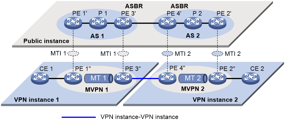
To implement MVPN inter-AS option A, a separate MVPN must be created in each AS. Multicast data is transmitted between the VPNs in different ASs through the MDs.
Multicast packets of VPN instance 1 are delivered as follows:
1. CE 1 forwards the multicast packet of VPN instance 1 to PE 1.
2. PE 1 encapsulates the multicast packet into a public network packet and forwards it to PE 3 through the MTI interface in MVPN 1.
3. PE 3 considers PE 4 as a CE of VPN instance 1, so PE 3 forwards the multicast packet to PE 4.
4. PE 4 considers PE 3 as a CE of VPN instance 2, so it forwards the multicast packet to PE 2 through the MTI interface in MVPN 2 on the public network.
5. PE 2 forwards the multicast packet to CE 2.
Because only VPN multicast data is forwarded between ASBRs, different PIM modes can run within different ASs. However, the same PIM mode must run on all interfaces that belong to the same VPN (including interfaces with VPN bindings on ASBRs).
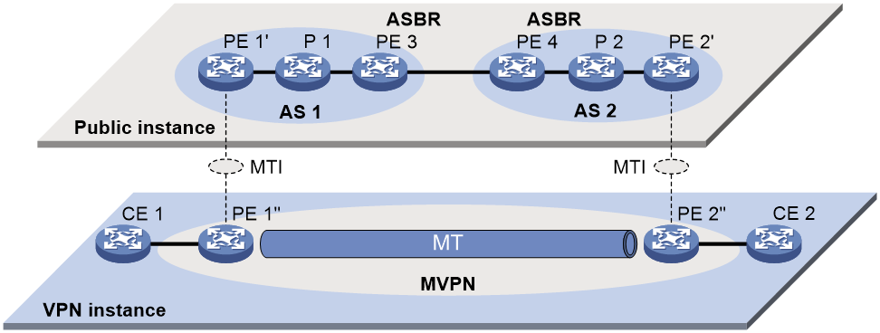
MDT-based MVPN inter-AS option B
In MVPN inter-AS option B, RPF vector and BGP connector are introduced:
· RPF vector—Attribute encapsulated in a PIM join message. It is the next hop of BGP MDT route from the local PE to the remote PE. Typically, it is the ASBR in the local AS.
When a device receives the join message with the RPF vector, it first checks whether the RPF vector is its own IP address. If so, the device removes the RPF vector, and sends the message to its upstream neighbor according to the route to the remote PE. Otherwise, it keeps the RPF vector, looks up the route to the RPF vector, and sends the message to the next hop of the route. In this way, the PIM message can be forwarded across the ASs and an MDT is established.
· BGP connector—Attribute shared by BGP peers when they exchange IPv4 VPN routes. It is the IP address of the remote PE.
The local PE fills the upstream neighbor address field with the BGP connector in a join message. This ensures that the message can pass the RPF check on the remote PE after it travels along the MT.
To implement MVPN inter-AS option B, only one MVPN needs to be established for the two ASs. VPN multicast data is transmitted between different ASs on the public network within this MVPN.
As shown in Figure 8:
· A VPN network involves AS 1 and AS 2.
· PE 3 and PE 4 are the ASBRs for AS 1 and AS 2, respectively.
· PE 3 and PE 4 are interconnected through MP-EBGP and treat each other as a P device.
· PE 3 and PE 4 advertise VPN-IPv4 routes to each other through MP-EBGP.
· An MT is established between PE 1 and PE 2 for delivering VPN multicast traffic across the ASs.
Figure 8 MVPN inter-AS option B

The establishment of the MDT on the public network is as follows:
1. PE 1 originates a PIM join message to join the SPT rooted at PE 2. In the join message, the upstream neighbor address is the IP address of PE 2 (the BGP connector). The RPF vector attribute is the IP address of PE 3. PE 1 encapsulates the join message as a public network packet and forwards it through the MTI.
2. P 1 determines that the RPF vector is not an IP address of its own. It looks up the routing table for a route to PE 3, and forwards the packet to PE 3.
3. PE 3 removes the RPF vector because the RPF vector is its own IP address. It fails to find a BGP MDT route to PE 2, so it encapsulates a new RPF vector (IP address of PE 4) in the packet and forwards it to PE 4.
4. PE 4 removes the RPF vector because the RPF vector is its own IP address. It has a local route to PE 2, so it forwards the packet to P 2, which is the next hop of the route to PE 2.
5. P 2 sends the packet to PE 2.
6. PE 2 receives the packet on the MTI and decapsulates the packet. The receiving interface is the RPF interface of the RPF route back to PE 1 for the join message, and the join message passes the RPF check. The SPT from PE 1 to PE 2 is established.
When PE 1 joins the SPT rooted at PE 1, PE 2 also initiates a join process to the SPT rooted at PE 1. A MDT is established when the two SPTs are finished.
MDT-based MVPN inter-AS option C
As shown in Figure 9:
· A VPN network involves AS 1 and AS 2.
· PE 3 and PE 4 are the ASBRs for AS 1 and AS 2, respectively.
· PE 3 and PE 4 are interconnected through MP-EBGP and treat each other as a P device.
· PEs in different ASs establish a multihop MP-EBGP session to advertise VPN-IPv4 routes to each other.
Figure 9 MVPN inter-AS option C
To implement MVPN inter-AS option C, only one MVPN needs to be created for the two ASs. Multicast data is transmitted between the two ASs through the MVPN.
Multicast packets are delivered as follows:
1. CE 1 forwards the VPN instance multicast packet to PE 1.
2. PE 1 encapsulates the multicast packet into a public network multicast packet and forwards it to PE 3 through the MTI interface on the public network.
3. PE 3 and PE 4 are interconnected through MP-EBGP, so PE 3 forwards the public network multicast packet to PE 4 along the VPN IPv4 route.
4. The public network multicast packet arrives at the MTI interface of PE 2 in AS 2. PE 2 decapsulates the public network multicast packet and forwards the VPN multicast packet to CE 2.
Basic concepts in RSVP-TE-based MVPN
This section introduces the following concepts in RSVP-TE-based MVPN:
· MVPN—An MVPN logically defines the transmission boundary of the multicast traffic of a VPN over the public network. It also physically identifies all the PEs that support that VPN instance on the public network. Different VPN instances correspond to different MVPNs. All PEs in an MVPN are MVPN peers.
· Inclusive tunnel—Transmits all multicast packets (including multicast protocol packets and multicast data packets of all multicast groups) for an MVPN. Only one inclusive tunnel can be established between two PEs in the MVPN.
· Selective tunnel—Transmits multicast packets of one or more multicast groups for an MVPN. Multiple selective tunnels can be established between two PEs in the MVPN.
How RSVP-TE-based MVPN works
RSVP-TE-based MVPN operation
Packet transmission on the public network is transparent for a VPN instance. Each two PEs establish IBGP neighbor relationship and use BGP to advertise routing information for MVPN. The following types of routes are used to create RSVP-TE tunnels for an MVPN:
· Intra-AS I-PMSI A-D route—PEs use this type of route to establish inclusive tunnels.
· S-PMSI A-D route—The multicast source-side PE sends this type of route to receiver-side PEs for tunnel switchover when selective tunnel creation is enabled and the tunnel creation criterion is met.
· Leaf A-D route—A receiver-side PE that has attached receivers replies with a Leaf A-D route when it receives an S-PMSI A-D route from the multicast source-side PE. RSVP-TE creates selective tunnels between receiver-side PEs and the multicast-side PE based on the neighbor information contained in Leaf A-D routes.
· Source Active A-D route—The multicast source-side PE sends this type of route to receiver-side PEs to advertise the location of the multicast source.
· C-Multicast Route—After receiving the Source Active A-D route from the multicast source-side PE, a receiver-side PE replies with a C-Multicast route to request the multicast source-side PE to send multicast data.
Multicast packets of a VPN instance are seamlessly transmitted from a CE to the inclusive tunnel on the PE based on the PIM routing table. These packets are then transmitted to the remote PE through the inclusive tunnel. After receiving the packets, the remote PE decapsulates the packets to get the original private packets. The multicast source-side PE creates selective tunnels when multicast traffic that meets the tunnel switchover criterion arrives.
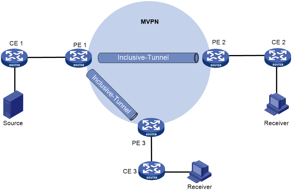
Inclusive tunnel establishment
As shown in Figure 10, the private network runs PIM, and the public network uses MPLS backbone. The inclusive tunnels are established as follows:
1. PE 1, PE 2, and PE 3 mutually establish IBGP neighbor relationship and exchange routing information to get the public network address of each PE.
2. The source of the tunnel (PE 1) sends an Intra-AS I-PMSI A-D route to the destination of the tunnel (PE 2 and PE 3) to advertise the inclusive tunnel information.
3. PE 2 and PE 3 each establish an inclusive tunnel with PE 1. The inclusive tunnel on the public network does not rely on PIM running on the private network.
Figure 10 Establishing inclusive tunnels
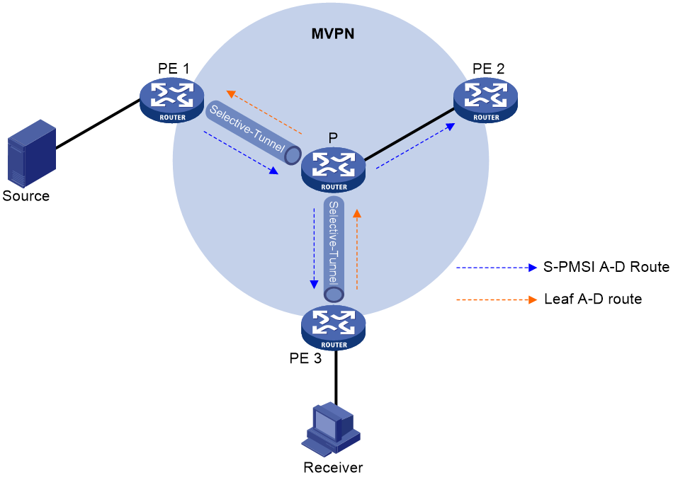
Selective tunnel establishment and tunnel switchover
As shown in Figure 11, selective tunnels are established and switched as follows:
1. After multicast source-side PE 1 receives a multicast packet of the (S, G) entry that meets the tunnel switchover criterion, it sends an S-PMSI A-D route to PE 2 and PE 3.
2. PE 2 does not send a response because it has no receivers of the (S,G) entry attached.
3. PE 3 replies with a Leaf A-D route because it is attached to a receiver of the entry.
4. PE 1 and PE 3 establish a selective tunnel.
5. Subsequent multicast packets of the (S,G) entry that enters the public network from PE 1 are switched to the selective tunnel from the inclusive tunnel.
Figure 11 Selective tunnel establishment
M6VPE
Overview
The multicast IPv6 VPN provider edge (M6VPE) feature enables PEs to transmit IPv6 multicast traffic of a VPN instance over the public network. Only the IPv4 network is available for the backbone network.
As shown in Figure 12, the public network runs IPv4 protocols, and sites of VPN instance VPN A run IPv6 multicast protocols. To transmit IPv6 multicast traffic between CE 1 and CE 2, configure M6VPE on the PEs.
IPv6 multicast traffic forwarding over the IPv4 public network is as follows:
1. CE 1 forwards an IPv6 multicast packet for VPN instance VPN A to PE 1.
2. PE 1 encapsulates the IPv6 multicast packet with an IPv4 packet header and transmits the IPv4 packet in the IPv4 backbone network.
3. PE 2 decapsulates the IPv4 packet and forwards the IPv6 multicast packet to CE 2.
Software version compatibility with M6VPE
This feature is supported only in Release 2719 and later.
Protocols and standards
· RFC 6037, Cisco Systems' Solution for Multicast in BGP/MPLS IP VPNs
· RFC 6513, Multicast in MPLS/BGP IP VPNs
· RFC 6514, BGP Encodings and Procedures for Multicast in MPLS/BGP IP VPNs
MDT-based MVPN tasks at a glance
To configure MDT-based MVPN, perform the following tasks on PEs:
a. Enabling IP multicast routing for a VPN instance
b. Creating an MDT-based MVPN instance
c. Creating an MVPN address family
d. Specifying the default-group
e. Specifying the MVPN source interface
f. (Optional.) Configuring MDT switchover parameters
g. (Optional.) Configuring the RPF vector feature
h. (Optional.) Enabling data-group reuse logging
i. (Optional.) Setting the DSCP value for outgoing data-group switchover packets
If PIM-SSM is running on the public network, you must configure BGP MDT.
a. Configuring BGP MDT peers or peer groups
b. (Optional.) Configuring a BGP MDT route reflector
c. (Optional.) Configuring BGP optimal route selection delay
RSVP-TE-based MVPN tasks at a glance
To configure RSVP-TE-based MVPN, perform the following tasks on PEs:
1. Enabling IP multicast routing for a VPN instance
2. Configuring BGP IPv4 MVPN route exchange
3. Adding extended community attributes to routes sent to BGP IPv4 MVPN neighbors
4. Creating an RSVP-TE-based MVPN instance
5. Creating an MVPN IPv4 address family
6. Specifying the MVPN source interface
7. Enabling inclusive tunnel creation
8. (Optional.) Enabling selective tunnel creation
9. (Optional.) Setting the tunnel switchover delay
Configuring MDT-based MVPN
Prerequisites for configuring MDT-based MVPN
Before you configure MDT-based MVPN, complete the following tasks:
· Configure a unicast routing protocol on the public network.
· Configure MPLS L3VPN on the public network.
· Configure PIM-DM, PIM-SM, BIDIR-PIM, or PIM-SSM on the public network.
Enabling IP multicast routing for a VPN instance
1. Enter system view.
system-view
2. Create a VPN instance and enter its view.
ip vpn-instance vpn-instance-name
For more information about this command, see MPLS Command Reference.
3. Configure an RD for the VPN instance.
route-distinguisher route-distinguisher
For more information about this command, see MPLS Command Reference.
4. Return to system view.
quit
5. Enter interface view.
interface interface-type interface-number
6. Associate the interface with the VPN instance.
ip binding vpn-instance vpn-instance-name
By default, an interface is associated with no VPN instance and belongs to the public network.
For more information about this command, see MPLS Command Reference.
7. Return to system view.
quit
8. Enable IP multicast routing for the VPN instance and enter MRIB view of the VPN instance.
¡ Enable IPv4 multicast routing and enter MRIB view of the VPN instance.
multicast routing vpn-instance vpn-instance-name
By default, IPv4 multicast routing is disabled for a VPN instance.
For more information about this command, see IP Multicast Command Reference.
¡ Enable IPv6 multicast routing and enter IPv6 MRIB view of the VPN instance.
ipv6 multicast routing vpn-instance vpn-instance-name
By default, IPv6 multicast routing is disabled for a VPN instance.
This command is supported only in Release 2719 and later.
For more information about this command, see IP Multicast Command Reference.
Creating an MDT-based MVPN instance
About creating an MDT-based MVPN instance
To provide multicast services for a VPN instance, you must create an MDT-based MVPN instance on PEs that belong to the VPN instance. After the MVPN instance is created, the system automatically creates MTIs and binds them with the VPN instance.
You can create one or more MDT-based MVPN instances on a PE.
Procedure
1. Enter system view.
system-view
2. Create an MDT-based MVPN instance and enter MVPN view.
multicast-vpn vpn-instance vpn-instance-name mode mdt
Creating an MVPN address family
About creating an MVPN address family
You must create an MVPN IPv4 or IPv6 address family for a VPN instance before you can perform other MVPN VPN configuration tasks for the VPN instance. For a VPN instance, configurations in MVPN IPv4 or IPv6 address family view apply only to IPv4 or IPv6 multicast packets of the instance.
Procedure
1. Enter system view.
system-view
2. Enter MVPN view of a VPN instance.
multicast-vpn vpn-instance vpn-instance-name mode mdt
3. Create an MVPN address family and enter MVPN address family view.
¡ Create an MVPN IPv4 address family and enter its view.
address-family ipv4
¡ Create an MVPN IPv6 address family and enter its view.
address-family ipv6
This command is supported only in Release 2719 and later.
Specifying the default-group
Restrictions and guidelines
You must specify the same default-group on all PEs that belong to the same MVPN.
The default-group for an MVPN must be different from the default-group and the data-group used by any other MVPN.
For an MVPN that transmits both IPv4 and IPv6 multicast packets, you must specify the same default-group in MVPN IPv4 address family view and IPv6 address family view.
Procedure
1. Enter system view.
system-view
2. Enter MVPN view.
multicast-vpn vpn-instance vpn-instance-name mode mdt
3. Enter MVPN address family view.
¡ Enter MVPN IPv4 address family view.
address-family ipv4
¡ Enter MVPN IPv6 address family view.
address-family ipv6
This command is supported only in Release 2719 and later.
4. Specify the default-group.
default-group group-address
Specifying the MVPN source interface
About MVPN source interfaces
An MTI of a VPN instance uses the IP address of the MVPN source interface as the source address to encapsulate multicast packets for the VPN instance.
Restrictions and guidelines
For the PE to obtain correct routing information, you must specify the interface used for establishing BGP peer relationship as the MVPN source interface.
For an MVPN that transmits both IPv4 and IPv6 multicast packets, you must specify the same MVPN source interface in MVPN IPv4 and IPv6 address family views.
The MTI takes effect only after the default-group and MVPN source interface are specified and the MTI obtains the public IP address of the MVPN source interface. On some devices, for the MTI to forward packets, you must create a service loopback group of the multicast type. For more information about creating service loopback groups, see Layer 2—LAN Switching Configuration Guide.
Procedure
1. Enter system view.
system-view
2. Enter MVPN view.
multicast-vpn vpn-instance vpn-instance-name mode mdt
3. Enter MVPN address family view.
¡ Enter MVPN IPv4 address family view.
address-family ipv4
¡ Enter MVPN IPv6 address family view.
address-family ipv6
This command is supported only in Release 2719 and later.
4. Specify the MVPN source interface.
source interface-type interface-number
By default, no MVPN source interface is specified.
Configuring MDT switchover parameters
About MDT switchover parameters
To decrease traffic interruption caused by frequent default-MDT to data-MDT switchovers, you can adjust the data-delay period. The switchover occurs a data-delay period after the multicast VPN data first arrives, regardless of whether multicast VPN data keeps arriving during the period.
Restrictions and guidelines
On a PE, the data-group range for an MVPN cannot include the default-group or data-groups of any other MVPN.
For an MVPN that transmits both IPv4 and IPv6 multicast packets, the data-group range in MVPN IPv4 and IPv6 address family views cannot overlap.
All VPN instances share the data-group resources. As a best practice to avoid data-group resource exhaustion, specify a reasonable data-group range for a VPN instance.
If the public network runs PIM-SSM, the data-group range for an MVPN on a PE can overlap with data-group ranges for other MDs on other PEs.
Procedure
1. Enter system view.
system-view
2. Enter MVPN view.
multicast-vpn vpn-instance vpn-instance-name mode mdt
3. Enter MVPN address family view.
¡ Enter MVPN IPv4 address family view.
address-family ipv4
¡ Enter MVPN IPv6 address family view.
address-family ipv6
This command is supported only in Release 2719 and later.
4. Configure the data-group range and the switchover criteria.
data-group group-address { mask-length | mask } [ acl acl-number ]
By default, no data-group range exists, and the default-MDT to data-MDT switchover never occurs.
5. Set the data-delay period.
data-delay delay
By default, the data-delay period is 3 seconds.
Configuring the RPF vector feature
About the RPF vector feature
This feature enables the device to insert the RPF vector (IP address of the ASBR in the local AS) in PIM join messages for other devices to perform RPF check.
Restrictions and guidelines
Perform this task on PEs that have attached receivers.
For the device to work with other manufacturers' products on the RPF vector, you must enable RPF vector compatibility for all H3C P devices and H3C PE devices on the public network.
Procedure
1. Enter system view.
system-view
2. Enter MRIB view of a VPN instance.
multicast routing vpn-instance vpn-instance-name
3. Enable the RPF vector feature.
rpf proxy vector
By default, the RPF vector feature is disabled.
4. Enable RPF vector compatibility.
multicast rpf-proxy-vector compatible
By default, RPF vector compatibility is disabled.
Enabling data-group reuse logging
About data-group reuse logging
For a given VPN, the number of VPN multicast streams to be switched to data-MDTs might exceed the number of addresses in the data-group range. In this case, the VPN instance on the source-side PE can reuse the addresses in the address range. With data-group reuse logging enabled, the address reuse information will be logged. Perform this task on PEs.
The group address reuse logging information has a severity level informational. For more information about the logging information, see Network Management and Monitoring Configuration Guide.
Procedure
1. Enter system view.
system-view
2. Enter MVPN view.
multicast-vpn vpn-instance vpn-instance-name mode mdt
3. Enter MVPN address family view.
¡ Enter MVPN IPv4 address family view.
address-family ipv4
¡ Enter MVPN IPv6 address family view.
address-family ipv6
This command is supported only in Release 2719 and later.
4. Enable data-group reuse logging.
log data-group-reuse
By default, data-group reuse logging is disabled.
Setting the DSCP value for outgoing data-group switchover packets
About the DSCP value for outgoing data-group switchover packets
The DSCP value determines the packet transmission priority. A greater DSCP value represents a higher priority.
Procedure
1. Enter system view.
system-view
2. Enter MVPN view.
multicast-vpn vpn-instance vpn-instance-name mode mdt
3. Setting the DSCP value for outgoing data-group switchover packets.
dscp dscp-value
By default, the DSCP value is 48 for outgoing data-group switchover packets.
Configuring BGP MDT
Configuring BGP MDT peers or peer groups
About BGP MDT peers and peer groups
Perform this task so that the PE can exchange MDT information with the BGP peer or peer group. MDT information includes the IP address of the PE and default-group to which the PE belongs. On a public network running PIM-SSM, the multicast VPN establishes a default-MDT rooted at the PE (multicast source) based on the MDT information.
Prerequisites
Before you configure a BGP MDT peer or peer group, you must create a BGP peer or peer group in BGP instance view. For more information about creating a BGP peer or peer group, see BGP in Layer 3—IP Routing Configuration Guide.
Procedure
1. Enter system view.
system-view
2. Enter BGP instance view.
bgp as-number [ instance instance-name ]
3. Create a BGP IPv4 MDT address family and enter its view.
address-family ipv4 mdt
By default, no BGP IPv4 address family exists.
4. Enable the device to exchange MDT routing information with the BGP peer or the peer group.
peer { group-name | ip-address [ mask-length ] } enable
By default, the device cannot exchange BGP MDT routing information with a BGP peer or peer group.
For more information about this command, see Layer 3—IP Routing Configuration Guide.
Configuring a BGP MDT route reflector
About configuring BGP MDT route reflectors
· Configuring a BGP MDT route reflector—BGP MDT peers in the same AS must be fully meshed to maintain connectivity. However, when multiple BGP MDT peers exist in an AS, connection establishment among them might result in increased costs. To reduce connections between BGP MDT peers, you can configure one of them as a route reflector and specify other devices as clients.
· Disabling routing reflection between clients—When clients establish BGP MDT connections with the route reflector, the route reflector forwards (or reflects) BGP MDT routing information between clients. The clients are not required to be fully meshed. To save bandwidth if the clients have been fully meshed, you can disable the routing reflection between clients by using the undo reflect between-clients command.
· Configuring the cluster ID of the route reflector—The route reflector and its clients form a cluster. Typically, a cluster has only one route reflector whose router ID identifies the cluster. However, you can configure several route reflectors in a cluster to improve network reliability. To avoid routing loops, make sure the route reflectors in a cluster have the same cluster ID.
Procedure
1. Enter system view.
system-view
2. Enter BGP instance view.
bgp as-number [ instance instance-name ]
3. Enter BGP IPv4 MDT address family view.
address-family ipv4 mdt
4. Configure the device as a route reflector and specify its peers or peer groups as clients.
peer { group-name | ip-address [ mask-length ] } reflect-client
By default, neither route reflectors nor clients exist.
5. (Optional.) Disable route reflection between clients.
undo reflect between-clients
By default, route reflection between clients is disabled.
For more information about this command, see Layer 3—IP Routing Command Reference.
6. (Optional.) Configure the cluster ID of the route reflector.
reflector cluster-id { cluster-id | ip-address }
By default, a route reflector uses its router ID as the cluster ID.
For more information about this command, see Layer 3—IP Routing Command Reference.
Configuring BGP optimal route selection delay
About this task
By default, when the optimal route in the BGP routing table changes or a higher-priority route is learned, BGP performs optimal route selection immediately. To avoid packet loss upon switchover between redundant links, you can perform this task to delay optimal route selection.
Software version compatibility
This feature is supported only in Release 2719P01 and later.
Procedure
1. Enter system view.
system-view
2. Enter BGP instance view.
bgp as-number [ instance instance-name ]
3. Create a BGP IPv4 MDT address family and enter its view.
address-family ipv4 mdt
4. Set the optimal route selection delay timer..
route-select delay delay-value
By default, the optimal route selection delay timer is 0 seconds, which means optimal route selection is not delayed.
For more information about this command, see BGP commands in Layer 3—IP Routing Command Reference.
Configuring RSVP-TE-based MVPN
Prerequisites for configuring RSVP-TE-based MVPN
Before you configure RSVP-TE-based MVPN, complete the following tasks:
· Configure a unicast routing protocol on the public network.
· Configure MPLS TE and RSVP on the public network.
· Configure BGP to enable PEs to mutually establish neighbor relationship.
Enabling IP multicast routing for a VPN instance
1. Enter system view.
system-view
2. Create a VPN instance and enter its view.
ip vpn-instance vpn-instance-name
For more information about this command, see MPLS Command Reference.
3. Configure an RD for the VPN instance.
route-distinguisher route-distinguisher
For more information about this command, see MPLS Command Reference.
4. Return to system view.
quit
5. Enter interface view.
interface interface-type interface-number
6. Associate the interface with the VPN instance.
ip binding vpn-instance vpn-instance-name
By default, an interface is associated with no VPN instance and belongs to the public network.
For more information about this command, see MPLS Command Reference.
7. Return to system view.
quit
8. Enable IP multicast routing for the VPN instance and enter MRIB view of the VPN instance.
IPv4:
multicast routing vpn-instance vpn-instance-name
By default, IPv4 multicast routing is disabled for a VPN instance.
For more information about this command, see IP Multicast Command Reference.
IPv6:
ipv6 multicast routing vpn-instance vpn-instance-name
By default, IPv6 multicast routing is disabled for a VPN instance.
This command is supported only in Release 2719 and later.
For more information about this command, see IP Multicast Command Reference.
Configuring BGP IPv4 MVPN route exchange
1. Enter system view.
system-view
2. Enter BGP instance view.
bgp as-number [ instance instance-name ]
3. Specify a BGP MVPN peer and its AS number.
peer ipv4-address as-number as-number
4. Enter BGP IPv4 MVPN address family view.
address-family ipv4 mvpn
5. Enable BGP to exchange IPv4 unicast routing information with dynamic BGP peers.
peer ipv4-address mask-length enable
By default, BGP cannot exchange IPv4 unicast routing information with dynamic BGP peers.
For more information about this command, see BGP commands in Layer 3-IP Routing Command Reference.
6. (Optional.) Set the optimal route selection delay timer..
route-select delay delay-value
By default, the optimal route selection delay timer is 0 seconds, which means optimal route selection is not delayed.
This command is supported only in Release 2719P01 and later.
7. (Optional.) Disable route target filtering of received BGP IPv4 MVPN routes.
undo policy vpn-target
By default, a PE device filters route targets for received BGP IPv4 MVPN routes.
Adding extended community attributes to routes sent to BGP IPv4 MVPN neighbors
About adding extended community attributes
The following BGP extended community attributes are used to identify the route originator:
· Source AS Extended Community—Carries the number of AS where the MVPN source resides. The format of this attribute is 32-bit AS number::0, for example, 100:0.
· VRF Route Import Extended Community—Carries Router ID of the local BGP instance and the VPN instance to which the BGP VPNv4 route belongs. The format of the attribute is 32-bit router address:VPN instance index, for example, 192.168.122.15:1.
Restrictions and guidelines
Before you perform this task, you must establish BGP IPv4 MVPN neighbor relationship and specify BGP MVPN peers.
Procedure
1. Enter system view.
system-view
2. Enter BGP instance view.
bgp as-number [ instance instance-name ]
3. Enter BGP VPNv4 address family view.
address-family vpnv4
For more information about this command, see BGP commands in Layer 3-IP Routing Command Reference.
4. Add Source AS Extended Community and RF Route Import Extended Community to routes sent to BGP IPv4 MVPN neighbors.
mvpn-advertise-rt-import
By default, attributes Source AS Extended Community and RF Route Import Extended Community are not added to routes sent to BGP IPv4 MVPN neighbors.
Creating an RSVP-TE-based MVPN instance
About creating an RSVP-TE-based MVPN instance
You can create one or more RSVP-TE-based MVPN instances on a PE device.
A VPN instance supports only one MVPN mode.
Procedure
1. Enter system view.
system-view
2. Create an RSVP-TE-based MVPN instance and enter its view.
multicast-vpn vpn-instance vpn-instance-name mode rsvp-te
Creating an MVPN IPv4 address family
Restrictions and guidelines
Configurations in MVPN IPv4 address family view apply only to IPv4 multicast.
Procedure
1. Enter system view.
system-view
2. Enter MVPN view.
multicast-vpn vpn-instance vpn-instance-name mode rsvp-te
3. Create an MVPN IPv4 address family and enter its view.
address-family ipv4
Specifying the MVPN source interface
About MVPN source interfaces
The RSVP tunnel uses the IP address of the MVPN source interface as the source address to encapsulate multicast packets from the private network.
Restrictions and guidelines
For the PE to obtain correct routing information, you must specify the interface used for establishing BGP peer relationship as the MVPN source interface.
Procedure
1. Enter system view.
system-view
2. Enter MVPN view.
multicast-vpn vpn-instance vpn-instance-name mode rsvp-te
3. Enter MVPN IPv4 address family view.
address-family ipv4
4. Specify the MVPN source interface.
source interface-type interface-number
By default, no MVPN source interface is specified.
Enabling inclusive tunnel creation
Restrictions and guidelines
Once created, the inclusive tunnel always exists whether the multicast traffic is present or not.
Only one inclusive tunnel can be established between two PEs in an MVPN.
Procedure
1. Enter system view.
system-view
2. Enter MVPN view.
multicast-vpn vpn-instance vpn-instance-name mode rsvp-te
3. Enter MVPN IPv4 address family view.
address-family ipv4
4. Enable dynamic inclusive tunnel creation.
inclusive-tunnel dynamic
By default, dynamic inclusive tunnel creation is disabled.
Enabling selective tunnel creation
About selective tunnels
Multicast traffic that matches the tunnel switchover criterion is switched to selective tunnels from the inclusive tunnel after selective tunnel are created.
Restrictions and guidelines
Selective tunnels are created only after the multicast traffic is transmitted over the inclusive tunnel.
Multicast packets of multiple (S, G) entries can share one selective tunnel.
You can create multiple selective tunnels between two PEs in an MVPN. These selective tunnels are independent from one another.
Procedure
1. Enter system view.
system-view
2. Enter MVPN view.
multicast-vpn vpn-instance vpn-instance-name mode rsvp-te
3. Enter MVPN IPv4 address family view.
address-family ipv4
4. Enable dynamic selective tunnel creation.
selective-tunnel dynamic [ acl ipv4-acl-number ]
By default, dynamic selective tunnel creation is disabled.
Setting the tunnel switchover delay
About the tunnel switchover delay
To avoid multicast data loss during tunnel switchover, adjust the delay time for multicast data to switch from the inclusive tunnel to selective tunnels.
Procedure
1. Enter system view.
system-view
2. Enter MVPN view.
multicast-vpn vpn-instance vpn-instance-name mode rsvp-te
3. Enter MVPN IPv4 address family view.
address-family ipv4
4. Set the tunnel switchover delay.
selective-tunnel delay delay
By default, the tunnel switchover delay is 3 seconds.
Display and maintenance commands for multicast VPN
Execute display commands in any view and reset commands in user view.
Display and maintenance commands for MDT-based MVPN:
|
Task |
Command |
|
Display BGP MDT peer group information. |
display bgp [ instance instance-name ] group ipv4 mdt [ group-name group-name ] |
|
Display information about BGP MDT peers or peer groups. |
display bgp [ instance instance-name ] peer ipv4 mdt [ ip-address mask-length | { ip-address | group-name group-name } log-info | [ ip-address ] verbose ] |
|
Display information about BGP MVPN peers or peer groups. |
display bgp [ instance instance-name ] peer ipv4 mvpn [ ip-address mask-length | { ip-address | group-name group-name } log-info | [ ip-address ] verbose ] |
|
Display BGP MDT routing information. |
display bgp [ instance instance-name ] routing-table ipv4 mdt [ route-distinguisher route-distinguisher ] [ ip-address [ advertise-info ] ] |
|
Display information about BGP update groups for the BGP IPv4 MDT address family. |
display bgp [ instance instance-name ] update-group ipv4 mdt [ ip-address ] |
|
Display information about data-groups for IPv4 multicast transmission that are received in a VPN instance. |
display multicast-vpn vpn-instance vpn-instance-name data-group receive [ brief | [ active | group group-address | sender source-address | vpn-source-address [ mask { mask-length | mask } ] | vpn-group-address [ mask { mask-length | mask } ] ] * ] |
|
Display information about data groups for IPv6 multicast transmission that are received in a VPN instance. |
display multicast-vpn vpn-instance vpn-instance-name ipv6 data-group receive [ brief | [ active | group group-address | sender source-address | vpn-source-address [ mask-length ] | vpn-group-address [ mask-length ] ] * ] |
|
Display information about data-groups for IPv4 multicast transmission that are sent in a VPN instance. |
display multicast-vpn vpn-instance vpn-instance-name data-group send [ group group-address | reuse interval | vpn-source-address [ mask { mask-length | mask } ] | vpn-group-address [ mask { mask-length | mask } ] ] * |
|
Display information about data groups for IPv6 multicast transmission that are sent in a VPN instance. |
display multicast-vpn vpn-instance vpn-instance-name ipv6 data-group send [ group group-address | reuse interval | vpn-source-address [ mask-length ] | vpn-group-address [ mask-length ] ] * |
|
Display information about default-groups for IPv4 multicast transmission. |
display multicast-vpn [ vpn-instance vpn-instance-name ] default-group { local | remote } |
|
Display information about default groups for IPv6 multicast transmission. |
display multicast-vpn [ vpn-instance vpn-instance-name ] ipv6 default-group { local | remote } |
|
Reset BGP sessions for BGP IPv4 MDT address family. |
reset bgp [ instance instance-name ] { as-number | ip-address [ mask-length ] | all | external | group group-name | internal } ipv4 mdt |
Display and maintenance commands for RSVP-TE-based MVPN:
|
Task |
Command |
|
Display BGP MVPN peer group information. |
display bgp [ instance instance-name ] group ipv4 mvpn [ group-name group-name ] |
|
Display information about BGP MVPN peers or peer groups. |
display bgp [ instance instance-name ] peer ipv4 mvpn [ ip-address mask-length | { ip-address | group-name group-name } log-info | [ ip-address ] verbose ] |
|
Display information about BGP IPv4 MVPN routes. |
display bgp [ instance instance-name ] routing-table ipv4 mvpn [ route-distinguisher route-distinguisher [ route-type { intra-as I inter-as | s-pmsi | leaf | source-active | shared-tree | source-tree } ] ] | [ statistics ] display bgp [ instance instance-name ] routing-table ipv4 mvpn [ [ route-distinguisher route-distinguisher [ mvpn-prefix [ advertise-info ] ] ] display bgp [ instance instance-name ] routing-table ipv4 mvpn [ route-type { intra-as I inter-as | s-pmsi | leaf | source-active | shared-tree | source-tree } [ statistics ] ] display bgp [ instance instance-name ] routing-table ipv4 mvpn peer ip-address { advertised-routes | received-routes } [ statistics ] |
|
Display information about C-multicast A-D routes for RSVP-TE-based MVPN. |
display multicast-vpn vpn-instance vpn-instance-name c-multicast routing-table [ group-address [ mask { mask-length | mask } ] | source-address [ mask { mask-length | mask } ] | outgoing-interface { exclude | include | match } interface-type interface-number ] |
|
Display RSVP-TE tunnel neighbor information for MVPN. |
display multicast-vpn vpn-instance vpn-instance-name neighbor [ interface tunnel number ] |
For more information about the display bgp group, display bgp peer, display bgp update-group, and reset bgp commands, see Layer 3—IP Routing Command Reference.
Multicast VPN configuration examples
Example: Configuring intra-AS MDT-based MVPN
Network configuration
As shown in Figure 13, configure intra-AS MDT-based MVPN to meet the following requirements:
|
Item |
Network configuration |
|
Multicast sources and receivers |
· In VPN instance a, S 1 is a multicast source, and R 1, R 2 and R 3 are receivers. · In VPN instance b, S 2 is a multicast source, and R 4 is a receiver. · For VPN instance a, the default-group is 239.1.1.1, and the data-group range is 225.2.2.0 to 225.2.2.15. · For VPN instance b, the default-group is 239.2.2, and the data-group range is 225.4.4.0 to 225.4.4.15. |
|
VPN instances to which PE interfaces belong |
· PE 1: VLAN-interface 11 and VLAN-interface 20 belong to VPN instance a. VLAN-interface 12 and Loopback 1 belong to the public network instance. · PE 2: VLAN-interface 13 belongs to VPN instance b. VLAN-interface 14 belongs to VPN instance a. VLAN-interface 15 and Loopback 1 belong to the public network instance. · PE 3: VLAN-interface 17 belongs to VPN instance a. VLAN-interface 18 and Loopback 2 belong to VPN instance b. VLAN-interface 19 and Loopback 1 belong to the public network instance. |
|
Unicast routing protocols and MPLS |
· Configure OSPF on the public network, and configure RIP between the PEs and CEs. · Establish BGP peer connections between PE 1, PE 2, and PE 3 on their respective Loopback 1. · Configure MPLS on the public network. |
|
IP multicast routing |
· Enable IP multicast routing on the P device. · Enable IP multicast routing on the public network on PE 1, PE 2, and PE 3. · Enable IP multicast routing for VPN instance a on PE 1, PE 2, and PE 3. · Enable IP multicast routing for VPN instance b on PE 2 and PE 3. · Enable IP multicast routing on CE a1, CE a2, CE a3, CE b1, and CE b2. |
|
IGMP |
· Enable IGMPv2 on VLAN-interface 20 of PE 1. · Enable IGMPv2 on VLAN-interface 40 of CE a2, VLAN-interface 50 of CE a3, and VLAN-interface 60 of CE b2. |
|
PIM |
Enable PIM-SM on the public network and for VPN instances a and b: · Enable PIM-SM on all interfaces of the P device. · Enable PIM-SM on all public and private network interfaces of PE 1, PE 2, and PE 3. · Enable PIM-SM on all interfaces that have no receiver hosts connected of CE a1, CE a2, CE a3, CE b1, and CE b2. · Configure Loopback 1 of P as a C-BSR and a C-RP for the public network to provide services for all multicast groups. · Configure Loopback 1 of CE a2 as a C-BSR and a C-RP for VPN instance a to provide services for all multicast groups. · Configure Loopback 2 of PE 3 as a C-BSR and a C-RP for VPN instance b to provide services for all multicast groups. |
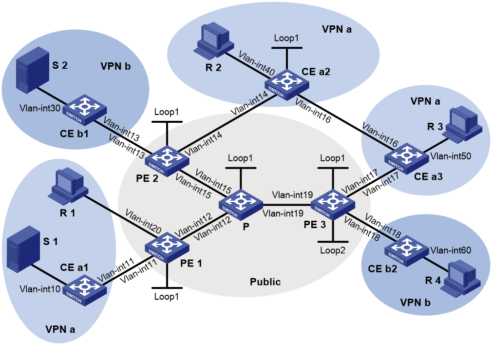
Table 1 Interface and IP address assignment
|
Device |
Interface |
IP address |
Device |
Interface |
IP address |
|
S 1 |
— |
10.110.7.2/24 |
PE 3 |
Vlan-int19 |
192.168.8.1/24 |
|
S 2 |
— |
10.110.8.2/24 |
PE 3 |
Vlan-int17 |
10.110.5.1/24 |
|
R 1 |
— |
10.110.1.2/24 |
PE 3 |
Vlan-int18 |
10.110.6.1/24 |
|
R 2 |
— |
10.110.9.2/24 |
PE 3 |
Loop1 |
1.1.1.3/32 |
|
R 3 |
— |
10.110.10.2/24 |
PE 3 |
Loop2 |
33.33.33.33/32 |
|
R 4 |
— |
10.110.11.2/24 |
CE a1 |
Vlan-int10 |
10.110.7.1/24 |
|
P |
Vlan-int12 |
192.168.6.2/24 |
CE a1 |
Vlan-int11 |
10.110.2.2/24 |
|
P |
Vlan-int15 |
192.168.7.2/24 |
CE a2 |
Vlan-int40 |
10.110.9.1/24 |
|
P |
Vlan-int19 |
192.168.8.2/24 |
CE a2 |
Vlan-int14 |
10.110.4.2/24 |
|
P |
Loop1 |
2.2.2.2/32 |
CE a2 |
Vlan-int16 |
10.110.12.1/24 |
|
PE 1 |
Vlan-int12 |
192.168.6.1/24 |
CE a2 |
Loop1 |
22.22.22.22/32 |
|
PE 1 |
Vlan-int20 |
10.110.1.1/24 |
CE a3 |
Vlan-int50 |
10.110.10.1/24 |
|
PE 1 |
Vlan-int11 |
10.110.2.1/24 |
CE a3 |
Vlan-int17 |
10.110.5.2/24 |
|
PE 1 |
Loop1 |
1.1.1.1/32 |
CE a3 |
Vlan-int16 |
10.110.12.2/24 |
|
PE 2 |
Vlan-int15 |
192.168.7.1/24 |
CE b1 |
Vlan-int30 |
10.110.8.1/24 |
|
PE 2 |
Vlan-int13 |
10.110.3.1/24 |
CE b1 |
Vlan-int13 |
10.110.3.2/24 |
|
PE 2 |
Vlan-int14 |
10.110.4.1/24 |
CE b2 |
Vlan-int60 |
10.110.11.1/24 |
|
PE 2 |
Loop1 |
1.1.1.2/32 |
CE b2 |
Vlan-int18 |
10.110.6.2/24 |
Procedure
|
|
IMPORTANT: By default, interfaces on the device are disabled (in ADM or Administratively Down state). To have an interface operate, you must use the undo shutdown command to enable that interface. |
1. Configure PE 1:
# Configure a global router ID, and enable IP multicast routing on the public network.
<PE1> system-view
[PE1] router id 1.1.1.1
[PE1] multicast routing
[PE1-mrib] quit
# Create service loopback group 1, and specify the multicast tunnel service for the group.
[PE1] service-loopback group 1 type multicast-tunnel
# Assign FortyGigE 1/0/4 to service loopback group 1. The interface does not belong to VLAN 11, VLAN 12, or VLAN 20.
[PE1] interface fortygige 1/0/4
[PE1-FortyGigE1/0/4] port service-loopback group 1
[PE1-FortyGigE1/0/4] quit
# Configure an LSR ID, and enable LDP globally.
[PE1] mpls lsr-id 1.1.1.1
[PE1] mpls ldp
[PE1-ldp] quit
# Create a VPN instance named a and configure an RD and route targets for the VPN instance.
[PE1] ip vpn-instance a
[PE1-vpn-instance-a] route-distinguisher 100:1
[PE1-vpn-instance-a] vpn-target 100:1 export-extcommunity
[PE1-vpn-instance-a] vpn-target 100:1 import-extcommunity
[PE1-vpn-instance-a] quit
# Enable IP multicast routing for VPN instance a.
[PE1] multicast routing vpn-instance a
[PE1-mrib-a] quit
# Create an MDT-based MVPN for VPN instance a.
[PE1] multicast-vpn vpn-instance a mode mdt
# Create an MVPN IPv4 family address for VPN instance a.
[PE1-mvpn-a] address-family ipv4
# Specify the default-group, the MVPN source interface, and the data-group range for VPN instance a.
[PE1-mvpn-a-ipv4] default-group 239.1.1.1
[PE1-mvpn-a-ipv4] source loopback 1
[PE1-mvpn-a-ipv4] data-group 225.2.2.0 28
[PE1-mvpn-a-ipv4] quit
[PE1-mvpn-a] quit
# Assign an IP address to VLAN-interface 12.
[PE1] interface vlan-interface 12
[PE1-Vlan-interface12] ip address 192.168.6.1 24
#Enable PIM-SM, MPLS, and IPv4 LDP on VLAN-interface 12.
[PE1-Vlan-interface12] pim sm
[PE1-Vlan-interface12] mpls enable
[PE1-Vlan-interface12] mpls ldp enable
[PE1-Vlan-interface12] quit
# Associate VLAN-interface 20 with VPN instance a.
[PE1] interface vlan-interface 20
[PE1-Vlan-interface20] ip binding vpn-instance a
# Assign an IP address to VLAN-interface 20, and enable IGMP on the interface.
[PE1-Vlan-interface20] ip address 10.110.1.1 24
[PE1-Vlan-interface20] igmp enable
[PE1-Vlan-interface20] quit
# Associate VLAN-interface 11 with VPN instance a.
[PE1] interface vlan-interface 11
[PE1-Vlan-interface11] ip binding vpn-instance a
# Assign an IP address to VLAN-interface 11, and enable PIM-SM on the interface.
[PE1-Vlan-interface11] ip address 10.110.2.1 24
[PE1-Vlan-interface11] pim sm
[PE1-Vlan-interface11] quit
# Assign an IP address to Loopback 1, and enable PIM-SM on the interface.
[PE1] interface loopback 1
[PE1-LoopBack1] ip address 1.1.1.1 32
[PE1-LoopBack1] pim sm
[PE1-LoopBack1] quit
# Configure BGP.
[PE1] bgp 100
[PE1-bgp-default] group vpn-g internal
[PE1-bgp-default] peer vpn-g connect-interface loopback 1
[PE1-bgp-default] peer 1.1.1.2 group vpn-g
[PE1-bgp-default] peer 1.1.1.3 group vpn-g
[PE1–bgp-default] ip vpn-instance a
[PE1-bgp-default-a] address-family ipv4
[PE1-bgp-default-ipv4-a] import-route rip 2
[PE1-bgp-default-ipv4-a] import-route direct
[PE1-bgp-default-ipv4-a] quit
[PE1-bgp-default-a] quit
[PE1–bgp-default] address-family vpnv4
[PE1–bgp-default-vpnv4] peer vpn-g enable
[PE1–bgp-default-vpnv4] quit
[PE1–bgp-default] quit
# Configure OSPF.
[PE1] ospf 1
[PE1-ospf-1] area 0.0.0.0
[PE1-ospf-1-area-0.0.0.0] network 1.1.1.1 0.0.0.0
[PE1-ospf-1-area-0.0.0.0] network 192.168.6.0 0.0.0.255
[PE1-ospf-1-area-0.0.0.0] quit
[PE1-ospf-1] quit
# Configure RIP.
[PE1] rip 2 vpn-instance a
[PE1-rip-2] network 10.110.1.0 0.0.0.255
[PE1-rip-2] network 10.110.2.0 0.0.0.255
[PE1-rip-2] import-route bgp
[PE1-rip-2] return
2. Configure PE 2:
# Configure a global router ID, and enable IP multicast routing on the public network.
<PE2> system-view
[PE2] router id 1.1.1.2
[PE2] multicast routing
[PE2-mrib] quit
# Create service loopback group 1, and specify the multicast tunnel service for the group.
[PE2] service-loopback group 1 type multicast-tunnel
# Assign FortyGigE 1/0/4 to service loopback group 1. The interface does not belong to VLAN 13, VLAN 14, or VLAN 15.
[PE2] interface fortygige 1/0/4
[PE2-FortyGigE1/0/4] port service-loopback group 1
[PE2-FortyGigE1/0/4] quit
# Configure an MPLS LSR ID, and enable LDP globally.
[PE2] mpls lsr-id 1.1.1.2
[PE2] mpls ldp
[PE2-ldp] quit
# Create a VPN instance named b, and configure an RD and route targets for the VPN instance.
[PE2] ip vpn-instance b
[PE2-vpn-instance-b] route-distinguisher 200:1
[PE2-vpn-instance-b] vpn-target 200:1 export-extcommunity
[PE2-vpn-instance-b] vpn-target 200:1 import-extcommunity
[PE2-vpn-instance-b] quit
# Enable IP multicast routing for VPN instance b.
[PE2] multicast routing vpn-instance b
[PE2-mrib-b] quit
# Create an MDT-based MVPN for VPN instance b.
[PE2] multicast-vpn vpn-instance b mode mdt
# Create an MVPN IPv4 address family for VPN instance b.
[PE2-mvpn-b] address-family ipv4
# Specify the default-group, the MVPN source interface, and the data-group range for VPN instance b.
[PE2-mvpn-b-ipv4] default-group 239.2.2.2
[PE2-mvpn-b-ipv4] source loopback 1
[PE2-mvpn-b-ipv4] data-group 225.4.4.0 28
[PE2-mvpn-b-ipv4] quit
[PE2-mvpn-b] quit
# Create a VPN instance named a, and configure an RD and route targets for VPN instance.
[PE2] ip vpn-instance a
[PE2-vpn-instance-a] route-distinguisher 100:1
[PE2-vpn-instance-a] vpn-target 100:1 export-extcommunity
[PE2-vpn-instance-a] vpn-target 100:1 import-extcommunity
[PE2-vpn-instance-a] quit
# Enable IP multicast routing for VPN instance a.
[PE2] multicast routing vpn-instance a
[PE2-mrib-a] quit
# Create an MDT-based MVPN for VPN instance a.
[PE2] multicast-vpn vpn-instance a mode mdt
# Create an MVPN IPv4 address family for VPN instance a.
[PE2-mvpn-a] address-family ipv4
# Specify the default-group, the MVPN source interface, and the data-group range for VPN instance a.
[PE2-mvpn-a-ipv4] default-group 239.1.1.1
[PE2-mvpn-a-ipv4] source loopback 1
[PE2-mvpn-a-ivp4] data-group 225.2.2.0 28
[PE2-mvpn-a-ipv4] quit
[PE2-mvpn-a] quit
# Assign an IP address to VLAN-interface 15.
[PE2] interface vlan-interface 15
[PE2-Vlan-interface15] ip address 192.168.7.1 24
# Enable PIM-SM, MPLS, and IPv4 LDP on VLAN-interface 15.
[PE2-Vlan-interface15] pim sm
[PE2-Vlan-interface15] mpls enable
[PE2-Vlan-interface15] mpls ldp enable
[PE2-Vlan-interface15] quit
# Associate VLAN-interface 13 with VPN instance b, assign an IP address to VLAN-interface 13, and enable PIM-SM on the interface.
[PE2] interface vlan-interface 13
[PE2-Vlan-interface13] ip binding vpn-instance b
[PE2-Vlan-interface13] ip address 10.110.3.1 24
[PE2-Vlan-interface13] pim sm
[PE2-Vlan-interface13] quit
# Associate VLAN-interface 14 with VPN instance a.
[PE2] interface vlan-interface 14
[PE2-Vlan-interface14] ip binding vpn-instance a
# Assign an IP address to VLAN-interface 14, and enable PIM-SM on the interface.
[PE2-Vlan-interface14] ip address 10.110.4.1 24
[PE2-Vlan-interface14] pim sm
[PE2-Vlan-interface14] quit
# Assign an IP address to Loopback 1, and enable PIM-SM on the interface.
[PE2] interface loopback 1
[PE2-LoopBack1] ip address 1.1.1.2 32
[PE2-LoopBack1] pim sm
[PE2-LoopBack1] quit
# Configure BGP.
[PE2] bgp 100
[PE2-bgp-default] group vpn-g internal
[PE2-bgp-default] peer vpn-g connect-interface loopback 1
[PE2-bgp-default] peer 1.1.1.1 group vpn-g
[PE2-bgp-default] peer 1.1.1.3 group vpn-g
[PE2–bgp-default] ip vpn-instance a
[PE2-bgp-default-a] address-family ipv4
[PE2-bgp-default-ipv4-a] import-route rip 2
[PE2-bgp-default-ipv4-a] import-route direct
[PE2-bgp-default-ipv4-a] quit
[PE2-bgp-default-a] quit
[PE2–bgp-default] ip vpn-instance b
[PE2-bgp-default-b] address-family ipv4
[PE2-bgp-default-ipv4-b] import-route rip 3
[PE2-bgp-default-ipv4-b] import-route direct
[PE2-bgp-default-ipv4-b] quit
[PE2-bgp-default-b] quit
[PE2–bgp-default] address-family vpnv4
[PE2–bgp-default-vpnv4] peer vpn-g enable
[PE2–bgp-default-vpnv4] quit
[PE2–bgp-default] quit
# Configure OSPF.
[PE2] ospf 1
[PE2-ospf-1] area 0.0.0.0
[PE2-ospf-1-area-0.0.0.0] network 1.1.1.2 0.0.0.0
[PE2-ospf-1-area-0.0.0.0] network 192.168.7.0 0.0.0.255
[PE2-ospf-1-area-0.0.0.0] quit
[PE2-ospf-1] quit
# Configure RIP.
[PE2] rip 2 vpn-instance a
[PE2-rip-2] network 10.110.3.0 0.0.0.255
[PE2-rip-2] import-route bgp
[PE2-rip-2] quit
[PE2] rip 3 vpn-instance b
[PE2-rip-3] network 10.110.4.0 0.0.0.255
[PE2-rip-3] import-route bgp
[PE2-rip-3] return
3. Configure PE 3:
# Configure a global router ID, and enable IP multicast routing on the public network.
<PE3> system-view
[PE3] router id 1.1.1.3
[PE3] multicast routing
[PE3-mrib] quit
# Create service loopback group 1, and specify the multicast tunnel service for the group.
[PE3] service-loopback group 1 type multicast-tunnel
# Assign FortyGigE 1/0/4 to service loopback group 1. The interface does not belong to VLAN 17, VLAN 18, or VLAN 19.
[PE3] interface fortygige 1/0/4
[PE3-FortyGigE1/0/4] port service-loopback group 1
[PE3-FortyGigE1/0/4] quit
# Configure an LSR ID, and enable LDP globally.
[PE3] mpls lsr-id 1.1.1.3
[PE3] mpls ldp
[PE3-ldp] quit
# Create a VPN instance named a, and configure an RD and route targets for the VPN instance.
[PE3] ip vpn-instance a
[PE3-vpn-instance-a] route-distinguisher 100:1
[PE3-vpn-instance-a] vpn-target 100:1 export-extcommunity
[PE3-vpn-instance-a] vpn-target 100:1 import-extcommunity
[PE3-vpn-instance-a] quit
# Enable IP multicast routing for VPN instance a.
[PE3] multicast routing vpn-instance a
[PE3-mrib-a] quit
# Create an MDT-based MVPN for VPN instance a.
[PE3] multicast-vpn vpn-instance a mode mdt
# Create an MVPN IPv4 address family for VPN instance a.
[PE3-mvpn-a] address-family ipv4
# Specify the default-group, the MVPN source interface, and the data-group range for VPN instance a.
[PE3-mvpn-a-ipv4] default-group 239.1.1.1
[PE3-mvpn-a-ipv4] source loopback 1
[PE3-mvpn-a-ipv4] data-group 225.2.2.0 28
[PE3-mvpn-a-ipv4] quit
[PE3-mvpn-a] quit
# Create a VPN instance named b, and configure an RD and route targets for the VPN instance.
[PE3] ip vpn-instance b
[PE3-vpn-instance-b] route-distinguisher 200:1
[PE3-vpn-instance-b] vpn-target 200:1 export-extcommunity
[PE3-vpn-instance-b] vpn-target 200:1 import-extcommunity
[PE3-vpn-instance-b] quit
# Enable IP multicast routing for VPN instance b.
[PE3] multicast routing vpn-instance b
[PE3-mrib-b] quit
# Create an MDT-based MVPN for VPN instance b.
[PE3] multicast-vpn vpn-instance b mode mdt
# Create an MVPN IPv4 address family for VPN instance b.
[PE3-mvpn-b] address-family ipv4
# Specify the default-group, the MVPN source interface, and the data-group range for VPN instance b.
[PE3-mvpn-b-ipv4] default-group 239.2.2.2
[PE3-mvpn-b-ipv4] source loopback 1
[PE3-mvpn-b-ipv4] data-group 225.4.4.0 28
[PE3-mvpn-b-ipv4] quit
[PE3-mvpn-b] quit
# Assign an IP address to VLAN-interface 19.
[PE3] interface vlan-interface 19
[PE3-Vlan-interface19] ip address 192.168.8.1 24
# Enable PIM-SM, MPLS, and IPv4 LDP on VLAN-interface 19.
[PE3-Vlan-interface19] pim sm
[PE3-Vlan-interface19] mpls enable
[PE3-Vlan-interface19] mpls ldp enable
[PE3-Vlan-interface19] quit
# Associate VLAN-interface 17 with VPN instance a.
[PE3] interface vlan-interface 17
[PE3-Vlan-interface17] ip binding vpn-instance a
# Assign an IP address to VLAN-interface 17, and enable PIM-SM on the interface.
[PE3-Vlan-interface17] ip address 10.110.5.1 24
[PE3-Vlan-interface17] pim sm
[PE3-Vlan-interface17] quit
# Associate VLAN-interface 18 with VPN instance b.
[PE3] interface vlan-interface 18
[PE3-Vlan-interface18] ip binding vpn-instance b
# Assign an IP address to VLAN-interface 18, and enable PIM-SM on the interface.
[PE3-Vlan-interface18] ip address 10.110.6.1 24
[PE3-Vlan-interface18] pim sm
[PE3-Vlan-interface18] quit
# Assign an IP address to Loopback 1, and enable PIM-SM on the interface.
[PE3] interface loopback 1
[PE3-LoopBack1] ip address 1.1.1.3 32
[PE3-LoopBack1] pim sm
[PE3-LoopBack1] quit
# Associate Loopback 2 with VPN instance b.
[PE3] interface loopback 2
[PE3-LoopBack2] ip binding vpn-instance b
# Assign an IP address to Loopback 2, and enable PIM-SM on the interface.
[PE3-LoopBack2] ip address 33.33.33.33 32
[PE3-LoopBack2] pim sm
[PE3-LoopBack2] quit
# Configure Loopback 2 as a C-BSR and a C-RP.
[PE3] pim vpn-instance b
[PE3-pim-b] c-bsr 33.33.33.33
[PE3-pim-b] c-rp 33.33.33.33
[PE3-pim-b] quit
# Configure BGP.
[PE3] bgp 100
[PE3-bgp-default] group vpn-g internal
[PE3-bgp-default] peer vpn-g connect-interface loopback 1
[PE3-bgp-default] peer 1.1.1.1 group vpn-g
[PE3-bgp-default] peer 1.1.1.2 group vpn-g
[PE3–bgp-default] ip vpn-instance a
[PE3-bgp-default-a] address-family ipv4
[PE3-bgp-default-ipv4-a] import-route rip 2
[PE3-bgp-default-ipv4-a] import-route direct
[PE3-bgp-default-ipv4-a] quit
[PE3-bgp-default-a] quit
[PE3–bgp-default] ip vpn-instance b
[PE3-bgp-default-b] address-family ipv4
[PE3-bgp-default-ipv4-b] import-route rip 3
[PE3-bgp-default-ipv4-b] import-route direct
[PE3-bgp-default-ipv4-b] quit
[PE3-bgp-default-b] quit
[PE3–bgp-default] address-family vpnv4
[PE3–bgp-default-vpnv4] peer vpn-g enable
[PE3–bgp-default-vpnv4] quit
[PE3–bgp-default] quit
# Configure OSPF.
[PE3] ospf 1
[PE3-ospf-1] area 0.0.0.0
[PE3-ospf-1-area-0.0.0.0] network 1.1.1.3 0.0.0.0
[PE3-ospf-1-area-0.0.0.0] network 192.168.8.0 0.0.0.255
[PE3-ospf-1-area-0.0.0.0] quit
[PE3-ospf-1] quit
# Configure RIP.
[PE3] rip 2 vpn-instance a
[PE3-rip-2] network 10.110.5.0 0.0.0.255
[PE3-rip-2] import-route bgp
[PE3-rip-2] quit
[PE3] rip 3 vpn-instance b
[PE3-rip-3] network 10.110.6.0 0.0.0.255
[PE3-rip-3] network 33.33.33.33 0.0.0.0
[PE3-rip-3] import-route bgp
[PE3-rip-3] return
4. Configure P:
# Enable IP multicast routing on the public network.
<P> system-view
[P] multicast routing
[P-mrib] quit
# Configure an MPLS LSR ID, and enable LDP globally.
[P] mpls lsr-id 2.2.2.2
[P] mpls ldp
[P-ldp] quit
# Assign an IP address to VLAN-interface 12.
[P] interface vlan-interface 12
[P-Vlan-interface12] ip address 192.168.6.2 24
# Enable PIM-SM, MPLS, and IPv4 LDP on VLAN-interface 12.
[P-Vlan-interface12] pim sm
[P-Vlan-interface12] mpls enable
[P-Vlan-interface12] mpls ldp enable
[P-Vlan-interface12] quit
# Assign an IP address to VLAN-interface 15.
[P] interface vlan-interface 15
[P-Vlan-interface15] ip address 192.168.7.2 24
# Enable PIM-SM, MPLS, and IPv4 LDP on VLAN-interface 15.
[P-Vlan-interface15] pim sm
[P-Vlan-interface15] mpls enable
[P-Vlan-interface15] mpls ldp enable
[P-Vlan-interface15] quit
# Assign an IP address to VLAN-interface 19.
[P] interface vlan-interface 19
[P-Vlan-interface19] ip address 192.168.8.2 24
# Enable PIM-SM, MPLS, and IPv4 LDP on VLAN-interface 19.
[P-Vlan-interface19] pim sm
[P-Vlan-interface19] mpls enable
[P-Vlan-interface19] mpls ldp enable
[P-Vlan-interface19] quit
# Assign an IP address to Loopback 1, and enable PIM-SM on the interface.
[P] interface loopback 1
[P-LoopBack1] ip address 2.2.2.2 32
[P-LoopBack1] pim sm
[P-LoopBack1] quit
# Configure Loopback 1 as a C-BSR and a C-RP.
[P] pim
[P-pim] c-bsr 2.2.2.2
[P-pim] c-rp 2.2.2.2
[P-pim] quit
# Configure OSPF.
[P] ospf 1
[P-ospf-1] area 0.0.0.0
[P-ospf-1-area-0.0.0.0] network 2.2.2.2 0.0.0.0
[P-ospf-1-area-0.0.0.0] network 192.168.6.0 0.0.0.255
[P-ospf-1-area-0.0.0.0] network 192.168.7.0 0.0.0.255
[P-ospf-1-area-0.0.0.0] network 192.168.8.0 0.0.0.255
5. Configure CE a1:
# Enable IP multicast routing.
<CEa1> system-view
[CEa1] multicast routing
[CEa1-mrib] quit
# Assign an IP address to VLAN-interface 10, and enable PIM-SM on the interface.
[CEa1] interface vlan-interface 10
[CEa1-Vlan-interface10] ip address 10.110.7.1 24
[CEa1-Vlan-interface10] pim sm
[CEa1-Vlan-interface10] quit
# Assign an IP address to VLAN-interface 11, and enable PIM-SM on the interface.
[CEa1] interface vlan-interface 11
[CEa1-Vlan-interface11] ip address 10.110.2.2 24
[CEa1-Vlan-interface11] pim sm
[CEa1-Vlan-interface11] quit
# Configure RIP.
[CEa1] rip 2
[CEa1-rip-2] network 10.110.2.0 0.0.0.255
[CEa1-rip-2] network 10.110.7.0 0.0.0.255
6. Configure CE b1:
# Enable IP multicast routing.
<CEb1> system-view
[CEb1] multicast routing
[CEb1-mrib] quit
# Assign an IP address to VLAN-interface 30, and enable PIM-SM on the interface.
[CEb1] interface vlan-interface 30
[CEb1-Vlan-interface30] ip address 10.110.8.1 24
[CEb1-Vlan-interface30] pim sm
[CEb1-Vlan-interface30] quit
# Assign an IP address to VLAN-interface 13, and enable PIM-SM on the interface.
[CEb1] interface vlan-interface 13
[CEb1-Vlan-interface13] ip address 10.110.3.2 24
[CEb1-Vlan-interface13] pim sm
[CEb1-Vlan-interface13] quit
# Configure RIP.
[CEb1] rip 3
[CEb1-rip-3] network 10.110.3.0 0.0.0.255
[CEb1-rip-3] network 10.110.8.0 0.0.0.255
7. Configure CE a2:
# Enable IP multicast routing.
<CEa2> system-view
[CEa2] multicast routing
[CEa2-mrib] quit
# Assign an IP address to VLAN-interface 40, and enable IGMP on the interface.
[CEa2] interface vlan-interface 40
[CEa2-Vlan-interface40] ip address 10.110.9.1 24
[CEa2-Vlan-interface40] igmp enable
[CEa2-Vlan-interface40] quit
# Assign an IP address to VLAN-interface 14, and enable PIM-SM on the interface.
[CEa2] interface vlan-interface 14
[CEa2-Vlan-interface14] ip address 10.110.4.2 24
[CEa2-Vlan-interface14] pim sm
[CEa2-Vlan-interface14] quit
# Assign an IP address to VLAN-interface 16, and enable PIM-SM on the interface.
[CEa2] interface vlan-interface 16
[CEa2-Vlan-interface16] ip address 10.110.12.1 24
[CEa2-Vlan-interface16] pim sm
[CEa2-Vlan-interface16] quit
# Assign an IP address to Loopback 1, and enable PIM-SM on the interface.
[CEa2] interface loopback 1
[CEa2-LoopBack1] ip address 22.22.22.22 32
[CEa2-LoopBack1] pim sm
[CEa2-LoopBack1] quit
# Configure Loopback 1 as a C-BSR and a C-RP.
[CEa2] pim
[CEa2-pim] c-bsr 22.22.22.22
[CEa2-pim] c-rp 22.22.22.22
[CEa2-pim] quit
# Configure RIP.
[CEa2] rip 2
[CEa2-rip-2] network 10.110.4.0 0.0.0.255
[CEa2-rip-2] network 10.110.9.0 0.0.0.255
[CEa2-rip-2] network 10.110.12.0 0.0.0.255
[CEa2-rip-2] network 22.22.22.22 0.0.0.0
8. Configure CE a3:
# Enable IP multicast routing.
<CEa3> system-view
[CEa3] multicast routing
[CEa3-mrib] quit
# Assign an IP address to VLAN-interface 50, and enable IGMP on the interface.
[CEa3] interface vlan-interface 50
[CEa3-Vlan-interface50] ip address 10.110.10.1 24
[CEa3-Vlan-interface50] igmp enable
[CEa3-Vlan-interface50] quit
# Assign an IP address to VLAN-interface 17, and enable PIM-SM on the interface.
[CEa3] interface vlan-interface 17
[CEa3-Vlan-interface17] ip address 10.110.5.2 24
[CEa3-Vlan-interface17] pim sm
[CEa3-Vlan-interface17] quit
# Assign an IP address to VLAN-interface 16, and enable PIM-SM on the interface.
[CEa3] interface vlan-interface 16
[CEa3-Vlan-interface16] ip address 10.110.12.2 24
[CEa3-Vlan-interface16] pim sm
[CEa3-Vlan-interface16] quit
# Configure RIP.
[CEa3] rip 2
[CEa3-rip-2] network 10.110.5.0 0.0.0.255
[CEa3-rip-2] network 10.110.10.0 0.0.0.255
[CEa3-rip-2] network 10.110.12.0 0.0.0.255
9. Configure CE b2:
# Enable IP multicast routing.
<CEb2> system-view
[CEb2] multicast routing
[CEb2-mrib] quit
# Assign an IP address to VLAN-interface 60, and enable IGMP on the interface.
[CEb2] interface vlan-interface 60
[CEb2-Vlan-interface60] ip address 10.110.11.1 24
[CEb2-Vlan-interface60] igmp enable
[CEb2-Vlan-interface60] quit
# Assign an IP address to VLAN-interface 18, and enable PIM-SM on the interface.
[CEb2] interface vlan-interface 18
[CEb2-Vlan-interface18] ip address 10.110.6.2 24
[CEb2-Vlan-interface18] pim sm
[CEb2-Vlan-interface18] quit
# Configure RIP.
[CEb2] rip 3
[CEb2-rip-3] network 10.110.6.0 0.0.0.255
[CEb2-rip-3] network 10.110.11.0 0.0.0.255
Verifying the configuration
# Display information about the local default-group for IPv4 multicast transmission in each VPN instance on PE 1.
[PE1] display multicast-vpn default-group local
MVPN local default-group information:
Group address Source address Interface VPN instance
239.1.1.1 1.1.1.1 MTunnel0 a
# Display information about the local default-group for IPv4 multicast transmission in each VPN instance on PE 2.
[PE2] display multicast-vpn default-group local
MVPN local default-group information:
Group address Source address Interface VPN instance
239.1.1.1 1.1.1.2 MTunnel0 a
239.1.1.1 1.1.1.2 MTunnel1 b
# Display information about the local default-group for IPv4 multicast transmission in each VPN instance on PE 3.
[PE3] display multicast-vpn default-group local
MVPN local default-group information:
Group address Source address Interface VPN instance
239.1.1.1 1.1.1.3 MTunnel0 a
239.2.2.2 1.1.1.3 MTunnel1 b
Example: Configuring intra-AS RSVP-TE-based MVPN
Network configuration
As shown in Figure 14, configure intra-AS RSVP-TE-based MVPN to meet the following requirements:
|
Item |
Network configuration |
|
Multicast sources and receivers |
· In VPN instance a, S 1 is a multicast source, and R 1, R 2, and R 3 are receivers. · In VPN instance b, S 2 is a multicast source, and R 4 is a receiver. |
|
VPN instances to which PE interfaces belong |
· PE 1: VLAN-interface 11 and VLAN-interface 20 belong to VPN instance a. VLAN-interface 12 and Loopback 1 belong to the public network. · PE 2: VLAN-interface 13 belongs to VPN instance b. VLAN-interface 19 and Loopback 1 belong to the public network. · PE 3: VLAN-interface 18 and Loopback 2 belongs to VPN instance b. VLAN-interface 19 and Loopback 1 belong to the public network. |
|
Unicast routing protocols and MPLS |
· Configure OSPF on the public network, and configure RIP between the PEs and the CEs. · Establish BGP peer connections between PE 1, PE 2, and PE 3 on their respective Loopback 1. · Configure MPLS TE and MPLS RSVP on the public network. |
|
IP multicast routing |
· Enable IP multicast routing for VPN instance a on PE 1 and PE 2. · Enable IP multicast routing for VPN instance b on PE 2 and PE 3. · Enable IP multicast routing on CE a1, CE a2, CE a3, CE b1, and CE b2. |
|
IGMP |
· Enable IGMPv2 on VLAN-interface 20 of CE b2. · Enable IGMPv2 on VLAN-interface 60 of CE b2, VLAN-interface 40 of CE a2, and \VLAN-interface 50 of CE a3. |
|
PIM |
· Enable PIM-SM on all interfaces on the P device. · Enable PIM-SM on all interfaces that do not have attached receiver hosts on PE 1, PE 2, and PE 3. · Enable PIM-SM on all interfaces that do not have attached receiver hosts on CE a1, CE a2, CE a3, CE b1, and CE b2. · Configure Loopback 1 of CE a2 as a C-BSR and a C-RP for VPN instance a to provide services for all multicast groups. · Configure Loopback 2 of PE 3 as a C-BSR and a C-RP for VPN instance b to provide services for all multicast groups. |
|
MSDP |
· Enable MSDP on CE a2, and specify VLAN-interface 14 as the local MSDP connection interface. · Enable MSDP on PE 2 for VPN instance a, and specify VLAN-interface 14 as the local MSDP connection interface. |

Table 2 Interface and IP address assignment
|
Device |
Interface |
IP address |
Device |
Interface |
IP address |
|
S 1 |
— |
10.110.7.2/24 |
PE 3 |
Vlan-int19 |
192.168.8.1/24 |
|
S 2 |
— |
10.110.8.2/24 |
PE 3 |
Vlan-int17 |
10.110.5.1/24 |
|
R 1 |
— |
10.110.1.2/24 |
PE 3 |
Vlan-int18 |
10.110.6.1/24 |
|
R 2 |
— |
10.110.9.2/24 |
PE 3 |
Loop1 |
1.1.1.3/32 |
|
R 3 |
— |
10.110.10.2/24 |
PE 3 |
Loop2 |
33.33.33.33/32 |
|
R 4 |
— |
10.110.11.2/24 |
CE a1 |
Vlan-int10 |
10.110.7.1/24 |
|
P |
Vlan-int12 |
192.168.6.2/24 |
CE a1 |
Vlan-int11 |
10.110.2.2/24 |
|
P |
Vlan-int15 |
192.168.7.2/24 |
CE a2 |
Vlan-int40 |
10.110.9.1/24 |
|
P |
Vlan-int19 |
192.168.8.2/24 |
CE a2 |
Vlan-int14 |
10.110.4.2/24 |
|
P |
Loop1 |
2.2.2.2/32 |
CE a2 |
Vlan-int16 |
10.110.12.1/24 |
|
PE 1 |
Vlan-int12 |
192.168.6.1/24 |
CE a2 |
Loop1 |
22.22.22.22/32 |
|
PE 1 |
Vlan-int20 |
10.110.1.1/24 |
CE a3 |
Vlan-int50 |
10.110.10.1/24 |
|
PE 1 |
Vlan-int11 |
10.110.2.1/24 |
CE a3 |
Vlan-int17 |
10.110.5.2/24 |
|
PE 1 |
Loop1 |
1.1.1.1/32 |
CE a3 |
Vlan-int16 |
10.110.12.2/24 |
|
PE 2 |
Vlan-int15 |
192.168.7.1/24 |
CE b1 |
Vlan-int30 |
10.110.8.1/24 |
|
PE 2 |
Vlan-int13 |
10.110.3.1/24 |
CE b1 |
Vlan-int13 |
10.110.3.2/24 |
|
PE 2 |
Vlan-int14 |
10.110.4.1/24 |
CE b2 |
Vlan-int60 |
10.110.11.1/24 |
|
PE 2 |
Loop1 |
1.1.1.2/32 |
CE b2 |
Vlan-int18 |
10.110.6.2/24 |
Procedure
|
|
IMPORTANT: By default, interfaces on the device are disabled (in ADM or Administratively Down state). To have an interface operate, you must use the undo shutdown command to enable that interface. |
1. Configure PE 1:
# Configure a global router ID.
<PE1> system-view
[PE1] router id 1.1.1.1
# Configure an LSR ID, and enable MPLS TE, MPLS LDP, and RSVP globally.
[PE1] mpls lsr-id 1.1.1.1
[PE1] mpls te
[PE1-te] quit
[PE1] rsvp
[PE1-rsvp] quit
[PE1] mpls ldp
[PE1-ldp] quit
# Create a VPN instance named a, and configure an RD and route targets for the VPN instance.
[PE1] ip vpn-instance a
[PE1-vpn-instance-a] route-distinguisher 100:1
[PE1-vpn-instance-a] vpn-target 100:1 export-extcommunity
[PE1-vpn-instance-a] vpn-target 100:1 import-extcommunity
[PE1-vpn-instance-a] quit
# Enable IP multicast routing in VPN instance a.
[PE1] multicast routing vpn-instance a
[PE1-mrib-a] quit
# Create an RSVP-TE-based MVPN for VPN instance a.
[PE1] multicast-vpn vpn-instance a mode rsvp-te
# Create an MVPN IPv4 address family for VPN instance a.
[PE1-mvpn-a] address-family ipv4
# Specify the MVPN source interface for VPN instance a.
[PE1-mvpn-a-ipv4] source loopback 1
# Enable dynamic inclusive tunnel creation.
[PE1-mvpn-a-ipv4] inclusive-tunnel dynamic
# Enable dynamic selective tunnel creation.
[PE1-mvpn-a-ipv4] selective-tunnel dynamic
[PE1-mvpn-a-ipv4] quit
[PE1-mvpn-a] quit
# Assign an IP address to VLAN-interface 12.
[PE1] interface vlan-interface 12
[PE1-Vlan-interface12] ip address 192.168.6.1 24
# Enable MPLS, MPLS TE, MPLS LDP and RSVP on VLAN-interface 12.
[PE1-Vlan-interface12] ip address 192.168.6.1 24
[PE1-Vlan-interface12] mpls enable
[PE1-Vlan-interface12] mpls te enable
[PE1-Vlan-interface12] mpls ldp enable
[PE1-Vlan-interface12] rsvp enable
[PE1-Vlan-interface12] quit
# Associate VLAN-interface 20 with VPN instance a.
[PE1] interface vlan-interface 20
[PE1-Vlan-interface20] ip binding vpn-instance a
# Assign an IP address to VLAN-interface 20, and enable IGMP on the interface.
[PE1-Vlan-interface20] ip address 10.110.1.1 24
[PE1-Vlan-interface20] igmp enable
[PE1-Vlan-interface20] quit
# Associate VLAN-interface 11 with VPN instance a.
[PE1] interface vlan-interface 11
[PE1-Vlan-interface11] ip binding vpn-instance a
# Assign an IP address to FortyGigE 1/0/3, and enable PIM-SM on the interface.
[PE1-Vlan-interface11] ip address 10.110.2.1 24
[PE1-Vlan-interface11] pim sm
[PE1-Vlan-interface11] quit
# Assign an IP address to Loopback 1.
[PE1] interface loopback 1
[PE1-LoopBack1] ip address 1.1.1.1 32
[PE1-LoopBack1] quit
# Configure BGP.
[PE1] bgp 100
[PE1-bgp-default] peer 1.1.1.2 as-number 100
[PE1-bgp-default] peer 1.1.1.2 connect-interface loopback 1
[PE1-bgp-default] peer 1.1.1.3 as-number 100
[PE1-bgp-default] peer 1.1.1.3 connect-interface loopback 1
[PE1-bgp-default] address-family ipv4 unicast
[PE1-bgp-default-ipv4] peer 1.1.1.2 enable
[PE1-bgp-default-ipv4] peer 1.1.1.3 enable
[PE1-bgp-default-ipv4] quit
[PE1-bgp-default] address-family ipv4 mvpn
[PE1-bgp-default-mvpn] peer 1.1.1.2 enable
[PE1-bgp-default-mvpn] peer 1.1.1.3 enable
[PE1-bgp-default-mvpn]quit
[PE1-bgp-default] address-family vpnv4
[PE1-bgp-default-vpnv4] mvpn-advertise-rt-import
[PE1-bgp-default-vpnv4] peer 1.1.1.2 enable
[PE1-bgp-default-vpnv4] peer 1.1.1.3 enable
[PE1-bgp-default-vpnv4] quit
[PE1–bgp-default] ip vpn-instance a
[PE1-bgp-default-a] address-family ipv4 unicast
[PE1-bgp-default-ipv4-a] import-route rip 2
[PE1-bgp-default-ipv4-a] import-route direct
[PE1-bgp-default-ipv4-a] quit
[PE1-bgp-default-a] quit
[PE1–bgp-default] quit
# Configure OSPF.
[PE1] ospf 1
[PE1-ospf-1] area 0.0.0.0
[PE1-ospf-1-area-0.0.0.0] network 1.1.1.1 0.0.0.0
[PE1-ospf-1-area-0.0.0.0] network 192.168.6.0 0.0.0.255
[PE1-ospf-1-area-0.0.0.0] quit
[PE1-ospf-1] quit
# Configure RIP.
[PE1] rip 2 vpn-instance a
[PE1-rip-2] network 10.110.1.0 0.0.0.255
[PE1-rip-2] network 10.110.2.0 0.0.0.255
[PE1-rip-2] import-route bgp
[PE1-rip-2] quit
2. Configure PE 2:
# Configure a global router ID.
<PE2> system-view
[PE2] router id 1.1.1.2
# Configure an LSR ID, and enable MPLS TE, MPLS LDP, and RSVP globally.
[PE2] mpls lsr-id 1.1.1.2
[PE2] mpls te
[PE2-te] quit
[PE2] mpls ldp
[PE2-ldp] quit
[PE2] rsvp
[PE2-rsvp] quit
# Create a VPN instance named b, and configure an RD and route targets for the VPN instance.
[PE2] ip vpn-instance b
[PE2-vpn-instance-b] route-distinguisher 200:1
[PE2-vpn-instance-b] vpn-target 200:1 export-extcommunity
[PE2-vpn-instance-b] vpn-target 200:1 import-extcommunity
[PE2-vpn-instance-b] quit
# Enable IP multicast routing for VPN instance b.
[PE2] multicast routing vpn-instance a
[PE2-mrib-a] quit
# Create an RSVP-TE-based MVPN for VPN instance b.
[PE2] multicast-vpn vpn-instance b mode rsvp-te
# Create an MVPN IPv4 address family for VPN instance b.
[PE2-mvpn-b] address-family ipv4
# Specify the MVPN source interface for VPN instance b.
[PE2-mvpn-b-ipv4] source loopback 1
# Enable dynamic inclusive tunnel creation.
[PE2-mvpn-b-ipv4] inclusive-tunnel dynamic
# Enable dynamic selective tunnel creation.
[PE2-mvpn-b-ipv4] selective-tunnel dynamic
[PE2-mvpn-b-ipv4] quit
[PE2-mvpn-b] quit
# Create a VPN instance named a, and configure an RD and route targets for the VPN instance.
[PE2] ip vpn-instance a
[PE2-vpn-instance-a] route-distinguisher 100:1
[PE2-vpn-instance-a] vpn-target 100:1 export-extcommunity
[PE2-vpn-instance-a] vpn-target 100:1 import-extcommunity
[PE2-vpn-instance-a] quit
# Enable IP multicast routing for VPN instance a.
[PE2] multicast routing vpn-instance a
[PE2-mrib-a] quit
# Enable MSDP for VPN instance a.
[PE2] msdp vpn-instance a
[PE2-msdp-a] peer 10.110.4.1 connect-interface vlan-interface 14
[PE2-msdp-a] quit
# Create an RSVP-TE-based MVPN for VPN instance a.
[PE2] multicast-vpn vpn-instance a mode rsvp-te
# Create an MVPN IPv4 address family for VPN instance a.
[PE2-mvpn-a] address-family ipv4
# Specify the MVPN source interface for VPN instance a.
[PE2-mvpn-a-ipv4] source loopback 1
# Enable dynamic inclusive tunnel creation.
[PE2-mvpn-a-ipv4] inclusive-tunnel dynamic
# Enable dynamic selective tunnel creation.
[PE2-mvpn-a-ipv4] selective-tunnel dynamic
[PE2-mvpn-a-ipv4] quit
[PE2-mvpn-a] quit
# Assign an IP address to VLAN-interface 15.
[PE2] interface vlan-interface 15
[PE2-Vlan-interface15] ip address 192.168.7.1 24
# Enable MPLS, MPLS TE, MPLS LDP, and RSVP on VLAN-interface 15.
[PE2-Vlan-interface15] mpls enable
[PE2-Vlan-interface15] mpls te enable
[PE2-Vlan-interface15] mpls ldp enable
[PE2-Vlan-interface15] rsvp enable
[PE2-Vlan-interface15] quit
# Associate VLAN-interface 13 with VPN instance b.
[PE2] interface vlan-interface 13
[PE2-Vlan-interface13] ip binding vpn-instance b
# Assign an IP address to VLAN-interface 13, and enable PIM-SM on the interface.
[PE2-Vlan-interface13] ip address 10.110.3.1 24
[PE2-Vlan-interface13] pim sm
[PE2-Vlan-interface13] quit
# Associate VLAN-interface 14 with VPN instance a.
[PE2] interface vlan-interface 14
[PE2-Vlan-interface14] ip binding vpn-instance a
# Assign an IP address to VLAN-interface 14, and enable PIM-SM on the interface.
[PE2-Vlan-interface14] ip address 10.110.4.1 24
[PE2-Vlan-interface14] pim sm
[PE2-Vlan-interface14] quit
# Assign an IP address to Loopback 1.
[PE2] interface loopback 1
[PE2-LoopBack1] ip address 1.1.1.2 32
[PE2-LoopBack1] quit
# Configure BGP.
[PE2] bgp 100
[PE2-bgp-default] peer 1.1.1.1 as-number 100
[PE2-bgp-default] peer 1.1.1.1 connect-interface loopback 1
[PE2-bgp-default] peer 1.1.1.3 as-number 100
[PE2-bgp-default] peer 1.1.1.3 connect-interface loopback 1
[PE2-bgp-default] address-family ipv4 unicast
[PE2-bgp-default-ipv4] peer 1.1.1.1 enable
[PE2-bgp-default-ipv4] peer 1.1.1.3 enable
[PE2-bgp-default-ipv4] quit
[PE2-bgp-default] address-family ipv4 mvpn
[PE2-bgp-default-mvpn] peer 1.1.1.1 enable
[PE2-bgp-default-mvpn] peer 1.1.1.3 enable
[PE2-bgp-default-mvpn]quit
[PE2-bgp-default] address-family vpnv4
[PE2-bgp-default-vpnv4] mvpn-advertise-rt-import
[PE2-bgp-default-vpnv4] peer 1.1.1.1 enable
[PE2-bgp-default-vpnv4] peer 1.1.1.3 enable
[PE2-bgp-default-vpnv4] quit
[PE2–bgp-default] ip vpn-instance a
[PE2-bgp-default-a] address-family ipv4 unicast
[PE2-bgp-default-ipv4-a] import-route rip 2
[PE2-bgp-default-ipv4-a] import-route direct
[PE2-bgp-default-ipv4-a] quit
[PE2-bgp-default-a] quit
[PE2–bgp-default] ip vpn-instance b
[PE2-bgp-default-b] address-family ipv4 unicast
[PE2-bgp-default-ipv4-b] import-route rip 3
[PE2-bgp-default-ipv4-b] import-route direct
[PE2-bgp-default-ipv4-b] quit
[PE2-bgp-default-b] quit
[PE2–bgp-default] quit
# Configure OSPF.
[PE2] ospf 1
[PE2-ospf-1] area 0.0.0.0
[PE2-ospf-1-area-0.0.0.0] network 1.1.1.2 0.0.0.0
[PE2-ospf-1-area-0.0.0.0] network 192.168.7.0 0.0.0.255
[PE2-ospf-1-area-0.0.0.0] quit
[PE2-ospf-1] quit
# Configure RIP.
[PE2] rip 2 vpn-instance a
[PE2-rip-2] network 10.110.4.0 0.0.0.255
[PE2-rip-2] import-route bgp
[PE2-rip-2] quit
[PE2] rip 3 vpn-instance b
[PE2-rip-3] network 10.110.3.0 0.0.0.255
[PE2-rip-3] import-route bgp
[PE2-rip-3] return
3. Configure PE 3:
# Configure a global router ID.
<PE3> system-view
[PE3] router id 1.1.1.3
# Configure an LSR ID, and enable MPLS TE, MPLS LDP, and RSVP globally.
[PE3] mpls lsr-id 1.1.1.3
[PE3] mpls te
[PE3-te] quit
[PE3] mpls ldp
[PE3-ldp] quit
[PE3] rsvp
[PE3-rsvp] quit
# Create a VPN instance named a, and configure an RD and route targets for the VPN instance.
[PE3] ip vpn-instance a
[PE3-vpn-instance-a] route-distinguisher 100:1
[PE3-vpn-instance-a] vpn-target 100:1 export-extcommunity
[PE3-vpn-instance-a] vpn-target 100:1 import-extcommunity
[PE3-vpn-instance-a] quit
# Enable IP multicast routing for VPN instance a.
[PE3] multicast routing vpn-instance a
[PE3-mrib-a] quit
# Create an RSVP-TE-based MVPN for VPN instance a.
[PE3] multicast-vpn vpn-instance a mode rsvp-te
# Create an MVPN IPv4 address family for VPN instance a.
[PE3-mvpn-a] address-family ipv4
# Specify the MVPN source interface for VPN instance a.
[PE3-mvpn-a-ipv4] source loopback 1
# Enable dynamic inclusive tunnel creation.
[PE3-mvpn-a-ipv4] inclusive-tunnel dynamic
# Enable dynamic selective tunnel creation.
[PE3-mvpn-a-ipv4] selective-tunnel dynamic
[PE3-mvpn-a-ipv4] quit
[PE3-mvpn-a] quit
# Create a VPN instance named b, and configure an RD and route targets for the VPN instance.
[PE3] ip vpn-instance b
[PE3-vpn-instance-b] route-distinguisher 200:1
[PE3-vpn-instance-b] vpn-target 200:1 export-extcommunity
[PE3-vpn-instance-b] vpn-target 200:1 import-extcommunity
[PE3-vpn-instance-b] quit
# Enable IP multicast routing for VPN instance b.
[PE3] multicast routing vpn-instance b
[PE3-mrib-b] quit
# Create an RSVP-TE-based MVPN for VPN instance b.
[PE3] multicast-vpn vpn-instance b mode rsvp-te
# Create an MVPN IPv4 address family for VPN instance b.
[PE3-mvpn-b] address-family ipv4
# Specify the MVPN source interface for VPN instance b.
[PE3-mvpn-b-ipv4] source loopback 1
# Enable dynamic inclusive tunnel creation.
[PE3-mvpn-b-ipv4] inclusive-tunnel dynamic
# Enable dynamic selective tunnel creation.
[PE3-mvpn-b-ipv4] selective-tunnel dynamic
[PE3-mvpn-b-ipv4] quit
[PE3-mvpn-b] quit
# Assign an IP address to VLAN-interface 19.
[PE3] interface vlan-interface 19
[PE3-Vlan-interface19] ip address 192.168.8.1 24
# Enable MPLS, MPLS-TE, MPLS LDP, and RSVP on VLAN-interface 19.
[PE3-Vlan-interface19] mpls enable
[PE3-Vlan-interface19] mpls te enable
[PE3-Vlan-interface19] mpls ldp enable
[PE3-Vlan-interface19] rsvp enable
[PE3-Vlan-interface19] quit
# Associate VLAN-interface 17 with VPN instance a.
[PE3] interface vlan-interface 17
[PE3-Vlan-interface17] ip binding vpn-instance a
# Assign an IP address to VLAN-interface 17, and enable PIM-SM on the interface.
[PE3-Vlan-interface17] ip address 10.110.5.1 24
[PE3-Vlan-interface17] pim sm
[PE3-Vlan-interface17] quit
# Associate VLAN-interface 18 with VPN instance b.
[PE3] interface vlan-interface 18
[PE3-Vlan-interface18] ip binding vpn-instance b
# Assign an IP address to VLAN-interface 18, and enable PIM-SM on the interface.
[PE3-Vlan-interface18] ip address 10.110.6.1 24
[PE3-Vlan-interface18] pim sm
[PE3-Vlan-interface18] quit
# Assign an IP address to Loopback 1.
[PE3] interface loopback 1
[PE3-LoopBack1] ip address 1.1.1.3 32
[PE3-LoopBack1] quit
# Associate Loopback 2 with VPN instance b.
[PE3] interface loopback 2
[PE3-LoopBack2] ip binding vpn-instance b
# Assign an IP address to Loopback 2, and enable PIM-SM on the interface.
[PE3-LoopBack2] ip address 33.33.33.33 32
[PE3-LoopBack2] pim sm
[PE3-LoopBack2] quit
# Configure Loopback 2 as a C-BSR and a C-RP.
[PE3] pim vpn-instance b
[PE3-pim-b] c-bsr 33.33.33.33
[PE3-pim-b] c-rp 33.33.33.33
[PE3-pim-b] quit
# Configure BGP.
[PE3] bgp 100
[PE3] mvpn-advertise-rt-import
[PE3-bgp-default] peer 1.1.1.1 as-number 100
[PE3-bgp-default] peer 1.1.1.1 connect-interface loopback 1
[PE3-bgp-default] peer 1.1.1.2 as-number 100
[PE3-bgp-default] peer 1.1.1.2 connect-interface loopback 1
[PE3-bgp-default] address-family ipv4 unicast
[PE3-bgp-default-ipv4] peer 1.1.1.1 enable
[PE3-bgp-default-ipv4] peer 1.1.1.2 enable
[PE3-bgp-default-ipv4] quit
[PE3-bgp-default] address-family ipv4 mvpn
[PE3-bgp-default-mvpn] peer 1.1.1.1 enable
[PE3-bgp-default-mvpn] peer 1.1.1.2 enable
[PE3-bgp-default-mvpn]quit
[PE3-bgp-default] address-family vpnv4
[PE3-bgp-default-vpnv4] mvpn-advertise-rt-import
[PE3-bgp-default-vpnv4] peer 1.1.1.1 enable
[PE3-bgp-default-vpnv4] peer 1.1.1.2 enable
[PE3-bgp-default-vpnv4] quit
[PE3–bgp-default] ip vpn-instance a
[PE3-bgp-default-a] address-family ipv4 unicast
[PE3-bgp-default-ipv4-a] import-route rip 2
[PE3-bgp-default-ipv4-a] import-route direct
[PE3-bgp-default-ipv4-a] quit
[PE3-bgp-default-a] quit
[PE3–bgp-default] quit
# Configure OSPF.
[PE3] ospf 1
[PE3-ospf-1] area 0.0.0.0
[PE3-ospf-1-area-0.0.0.0] network 1.1.1.3 0.0.0.0
[PE3-ospf-1-area-0.0.0.0] network 192.168.8.0 0.0.0.255
[PE3-ospf-1-area-0.0.0.0] quit
[PE3-ospf-1] quit
# Configure RIP.
[PE3] rip 2 vpn-instance a
[PE3-rip-2] network 10.110.5.0 0.0.0.255
[PE3-rip-2] import-route bgp
[PE3-rip-2] quit
[PE3] rip 3 vpn-instance b
[PE3-rip-3] network 10.110.6.0 0.0.0.255
[PE3-rip-3] network 33.33.33.33 0.0.0.0
[PE3-rip-3] import-route bgp
[PE3-rip-3] quit
4. Configuring the P router:
# Configure an LSR ID, and enable MPLS TE, MPLS LDP, and RSVP globally.
[P] mpls lsr-id 2.2.2.2
[P] mpls te
[P-te] quit
[P] mpls ldp
[P-ldp] quit
[P] rsvp
[P-rsvp] quit
# Assign an IP address to VLAN-interface 12.
[P] interface vlan-interface 12
[P-Vlan-interface12] ip address 192.168.6.2 24
# Enable MPLS, MPLS TE, MPLS LDP, and RSVP on VLAN-interface 12.
[P-Vlan-interface12] mpls enable
[P-Vlan-interface12] mpls te enable
[P-Vlan-interface12] mpls ldp enable
[P-Vlan-interface12] rsvp enable
[P-Vlan-interface12] quit
# Assign an IP address to VLAN-interface 15.
[P] interface vlan-interface 15
[P-Vlan-interface15] ip address 192.168.8.2 24
# Enable MPLS, MPLS TE, MPLS LDP, and RSVP on VLAN-interface 15.
[P-Vlan-interface15] mpls enable
[P-Vlan-interface15] mpls te enable
[P-Vlan-interface15] mpls ldp enable
[P-Vlan-interface15] rsvp enable
[P-Vlan-interface15] quit
# Assign an IP address to VLAN-interface 19.
[P] interface vlan-interface 19
[P-Vlan-interface19] ip address 192.168.8.2 24
# Enable MPLS, MPLS TE, MPLS LDP, and RSVP on VLAN-interface 10.
[P-Vlan-interface19] mpls enable
[P-Vlan-interface19] mpls te enable
[P-Vlan-interface19] mpls ldp enable
[P-Vlan-interface19] rsvp enable
[P-Vlan-interface19] quit
# Assign an IP address to Loopback 1.
[P] interface loopback 1
[P-LoopBack1] ip address 2.2.2.2 32
[P-LoopBack1] quit
# Configure OSPF.
[P] ospf 1
[P-ospf-1] area 0.0.0.0
[P-ospf-1-area-0.0.0.0] network 2.2.2.2 0.0.0.0
[P-ospf-1-area-0.0.0.0] network 192.168.6.0 0.0.0.255
[P-ospf-1-area-0.0.0.0] network 192.168.7.0 0.0.0.255
[P-ospf-1-area-0.0.0.0] network 192.168.8.0 0.0.0.255
[P-ospf-1-area-0.0.0.0] quit
[P-ospf-1] quit
5. Configure CE a1:
# Enable IP multicast routing.
<CEa1> system-view
[CEa1] multicast routing
[CEa1-mrib] quit
# Assign an IP address to VLAN-interface 10, and enable PIM-SM on the interface.
[CEa1] interface vlan-interface 10
[CEa1-Vlan-interface10] ip address 10.110.7.1 24
[CEa1-Vlan-interface10] pim sm
[CEa1-Vlan-interface10] quit
# Assign an IP address to VLAN-interface 11, and enable PIM-SM on the interface.
[CEa1] interface vlan-interface 11
[CEa1-Vlan-interface11] ip address 10.110.2.2 24
[CEa1-Vlan-interface11] pim sm
[CEa1-Vlan-interface11] quit
# Configure RIP.
[CEa1] rip 2
[CEa1-rip-2] network 10.110.2.0 0.0.0.255
[CEa1-rip-2] network 10.110.7.0 0.0.0.255
[CEa1-rip-2] quit
6. Configure CE b1:
# Enable IP multicast routing.
<CEb1> system-view
[CEb1] multicast routing
[CEb1-mrib] quit
# Assign an IP address to VLAN-interface 30, and enable PIM-SM on the interface.
[CEb1] interface vlan-interface 30
[CEb1-Vlan-interface30] ip address 10.110.8.1 24
[CEb1-Vlan-interface30] pim sm
[CEb1-Vlan-interface30] quit
# Assign an IP address to VLAN-interface 13, and enable PIM-SM on the interface.
[CEb1] interface vlan-interface 13
[CEb1-Vlan-interface13] ip address 10.110.3.2 24
[CEb1-Vlan-interface13] pim sm
[CEb1-Vlan-interface13] quit
# Configure RIP.
[CEb1] rip 3
[CEb1-rip-3] network 10.110.3.0 0.0.0.255
[CEb1-rip-3] network 10.110.8.0 0.0.0.255
[CEb1-rip-2] quit
7. Configure CE a2:
# Enable IP multicast routing.
<CEa2> system-view
[CEa2] multicast routing
[CEa2-mrib] quit
# Assign an IP address to VLAN-interface 40, and enable IGMP on the interface.
[CEa2] interface vlan-interface 40
[CEa2-Vlan-interface40] ip address 10.110.9.1 24
[CEa2-Vlan-interface40] igmp enable
[CEa2-Vlan-interface40] quit
# Assign an IP address to VLAN-interface 14, and enable PIM-SM on the interface.
[CEa2] interface vlan-interface 14
[CEa2-Vlan-interface14] ip address 10.110.4.2 24
[CEa2-Vlan-interface14] pim sm
[CEa2-Vlan-interface14] quit
# Assign an IP address to VLAN-interface 16, and enable PIM-SM on the interface.
[CEa2] interface vlan-interface 16
[CEa2-Vlan-interface16] ip address 10.110.12.1 24
[CEa2-Vlan-interface16] pim sm
[CEa2-Vlan-interface16] quit
# Assign an IP address to Loopback 1, and enable PIM-SM on the interface.
[CEa2] interface loopback 1
[CEa2-LoopBack1] ip address 22.22.22.22 32
[CEa2-LoopBack1] pim sm
[CEa2-LoopBack1] quit
# Configure Loopback 1 as a C-BSR and a C-RP.
[CEa2] pim vpn-instance a
[CEa2-pim] c-bsr 22.22.22.22
[CEa2-pim] c-rp 22.22.22.22
[CEa2-pim] quit
# Configure MSDP.
[CEa2-msdp] peer 10.110.4.2 connect-interface vlan-interface 16
[CEa2-msdp] quit
# Configure RIP.
[CEa2] rip 2
[CEa2-rip-2] network 10.110.4.0 0.0.0.255
[CEa2-rip-2] network 10.110.9.0 0.0.0.255
[CEa2-rip-2] network 10.110.12.0 0.0.0.255
[CEa2-rip-2] network 22.22.22.22 0.0.0.0
[CEa2-rip-2] quit
8. Configure CE a3:
# Enable IP multicast routing.
<CEa3> system-view
[CEa3] multicast routing
[CEa3-mrib] quit
# Assign an IP address to VLAN-interface 50, and enable IGMP on the interface.
[CEa3] interface vlan-interface 50
[CEa3-Vlan-interface50] ip address 10.110.10.1 24
[CEa3-Vlan-interface50] igmp enable
[CEa3-Vlan-interface50] quit
# Assign an IP address to VLAN-interface 17, and enable PIM-SM on the interface.
[CEa3] interface vlan-interface 17
[CEa3-Vlan-interface17] ip address 10.110.5.2 24
[CEa3-Vlan-interface17] pim sm
[CEa3-Vlan-interface17] quit
# Assign an IP address to VLAN-interface 16, and enable PIM-SM on the interface.
[CEa3] interface vlan-interface 16
[CEa3-Vlan-interface16] ip address 10.110.12.2 24
[CEa3-Vlan-interface16] pim sm
[CEa3-Vlan-interface16] quit
# Configure RIP.
[CEa3] rip 2
[CEa3-rip-2] network 10.110.5.0 0.0.0.255
[CEa3-rip-2] network 10.110.10.0 0.0.0.255
[CEa3-rip-2] network 10.110.12.0 0.0.0.255
[CEa3-rip-2] quit
9. Configure CE b2:
# Enable IP multicast routing.
<CEb2> system-view
[CEb2] multicast routing
[CEb2-mrib] quit
# Assign an IP address to VLAN-interface 60, and enable IGMP on the interface.
[CEb2] interface vlan-interface 60
[CEb2-Vlan-interface60] ip address 10.110.11.1 24
[CEb2-Vlan-interface60] igmp enable
[CEb2-Vlan-interface60] quit
# Assign an IP address to VLAN-interface 18, and enable PIM-SM on the interface.
[CEb2] interface vlan-interface 18
[CEb2-Vlan-interface18] ip address 10.110.6.2 24
[CEb2-Vlan-interface18] pim sm
[CEb2-Vlan-interface18] quit
# Configure RIP.
[CEb2] rip 3
[CEb2-rip-3] network 10.110.6.0 0.0.0.255
[CEb2-rip-3] network 10.110.11.0 0.0.0.255
[CEb2-rip-2] quit
Verifying the configuration
# Display the C-multicast A-D routing information VPN instances on PE 1.
[PE1] display multicast-vpn vpn-instance a c-multicast routing-table
Total 0 (*, G) entries; 1 (S, G) entries
(10.110.7.2, 225.0.0.1)
CreateTime: 02:54:43
Tunnel Information: Tunnel2
Leaf neigbours information:
Total number of Leaf neigbours: 2
1: 1.1.1.2
2: 1.1.1.3
# Display RSVP-TE tunnel neighbor information for VPN instances on PE 1.
[PE1] display multicast-vpn vpn-instance a neighbor
Total 1 Selective Tunnels in using
Total 0 Selective Tunnels in creating
Inclusive Tunnel : Tunnel1
Tunnel Identifier:<0x01010101, 0x0, 0x5, 0x01010101>
Neighbor State Up/DownTime
1.1.1.2 Up 02:50:49
1.1.1.3 Up 02:50:49
Selective Tunnel : Tunnel2
Tunnel Identifier:<0x01010101, 0x0, 0x8, 0x01010101>
Neighbor State Up/DownTime
1.1.1.2 Up 01:10:23
1.1.1.3 Up 01:10:23
# Display the C-multicast A-D routing information VPN instances on PE 2.
[PE2] display multicast-vpn vpn-instance b c-multicast routing-table
Total 0 (*, G) entries; 1 (S, G) entries
(10.110.8.2, 225.0.0.2)
UpTime: 02:54:43
Tunnel Information: Tunnel2
Leaf neigbours information:
Total number of Leaf neigbours: 1
1: 1.1.1.3
# Display RSVP-TE tunnel neighbor information for VPN instances on PE 2.
[PE2] display multicast-vpn vpn-instance b neighbor
Total 1 Selective Tunnels in using
Total 0 Selective Tunnels in creating
Inclusive Tunnel : Tunnel1
Tunnel Identifier:<0x01010102, 0x0, 0x8, 0x01010102>
Neighbor State Up/DownTime
1.1.1.3 Up 02:50:49
Selective Tunnel : Tunnel2
Tunnel Identifier:<0x01010102, 0x0, 0x8, 0x01010102>
Neighbor State Up/DownTime
1.1.1.3 Up 01:10:23
Example: Configuring intra-AS M6VPE
Network configuration
As shown in Figure 15, configure intra-AS M6VPE to meet the following requirements:
|
Item |
Network configuration |
|
Multicast sources and receivers |
· In VPN instance a, S 1 is an IPv6 multicast source, and R 1, R 2, and R 3 are receivers. · In VPN instance b, S 2 is an IPv6 multicast source, and R 4 is a receiver. · For VPN instance a, the default-group is 239.1.1.1, and the data-group range is 225.2.2.0 to 225.2.2.15. · For VPN instance b, the default-group is 239.2.2.2, and the data-group range is 225.4.4.0 to 225.4.4.15. |
|
VPN instances to which PE interfaces belong |
· PE 1: VLAN-interface 11 and VLAN-interface 20 belong to VPN instance a. VLAN-interface 12 and Loopback 1 belong to the public network. · PE 2: VLAN-interface 13 belongs to VPN instance b. VLAN-interface 14 belongs to VPN instance a. VLAN-interface 15 and Loopback 1 belong to the public network. · PE 3: VLAN-interface 17 belongs to VPN instance a. VLAN-interface 18 and Loopback 2 belongs to VPN instance b. VLAN-interface 19 and Loopback 1 belong to the public network. |
|
Unicast routing protocols and MPLS |
· Configure OSPF on the public network, and configure OSPFv3 between the PEs and the CEs. · Establish BGP peer connections between PE 1, PE 2, and PE 3 on their respective Loopback 1. · Configure MPLS on the public network. |
|
IP multicast routing and IPv6 multicast routing |
· Enable IP multicast routing on P. · Enable IP multicast routing for the public network on PE 1, PE 2, and PE 3. · Enable IPv6 multicast routing for VPN instance a on PE 1, PE 2, and PE 3. · Enable IPv6 multicast routing for VPN instance b on PE 2 and PE 3. · Enable IPv6 multicast routing on CE a1, CE a2, CE a3, CE b1, and CE b2. |
|
MLDv1 |
· Enable MLDv1 on VLAN-interface 20 of PE 1. · Enable MLDv1 on VLAN-interface 40 of CE a2. · Enable MLDv1 on VLAN-interface 50 of CE a3. · Enable MLDv1 on VLAN-interface 60 of CE b2. |
|
PIM and IPv6 PIM |
Enable PIM-SM on the public network and IPv6 PIM-SM for VPN instances a and b: · Enable PIM-SM on all interfaces of P. · Enable PIM-SM on all public network interfaces and IPv6 PIM-SM on private network interfaces of PE 1, PE 2, and PE 3. · Enable IPv6 PIM-SM on all interfaces that do not have attached receivers on CE a1, CE a2, CE a3, CE b1, and CE b2. · Configure Loopback 1 of P as a C-BSR and a C-RP for the public network to provide services for all IPv4 multicast groups. · Configure Loopback 1 of CE a2 as a C-BSR and a C-RP for VPN instance a to provide services for all IPv6 multicast groups. · Configure Loopback 2 of PE 3 as a C-BSR and a C-RP for VPN instance b to provide services for all IPv6 multicast groups. |

Table 3 Interface and IP address assignment
|
Device |
Interface |
IPv4/IPv6 address |
Device |
Interface |
IPv4/IPv6 address |
|
S 1 |
— |
10:110:7::2/64 |
PE 3 |
Vlan-int19 |
192.168.8.1/24 |
|
S 2 |
— |
10:110:8::2/64 |
PE 3 |
Vlan-int17 |
10:110:5::1/64 |
|
R 1 |
— |
10:110:1::2/64 |
PE 3 |
Vlan-int18 |
10:110:6::1/64 |
|
R 2 |
— |
10:110:9::2/64 |
PE 3 |
Loop1 |
1.1.1.3/32 |
|
R 3 |
— |
10:110:10::2/64 |
PE 3 |
Loop2 |
33:33:33::33/128 |
|
R 4 |
— |
10:110:11::2/64 |
CE a1 |
Vlan-int10 |
10:110:7::1/64 |
|
P |
Vlan-int12 |
192.168.6.2/24 |
CE a1 |
Vlan-int11 |
10:110:2::2/64 |
|
P |
Vlan-int15 |
192.168.7.2/24 |
CE a2 |
Vlan-int40 |
10:110:9::1/64 |
|
P |
Vlan-int19 |
192.168.8.2/24 |
CE a2 |
Vlan-int14 |
10:110:4::2/64 |
|
P |
Loop1 |
2.2.2.2/32 |
CE a2 |
Vlan-int16 |
10:110:12::1/64 |
|
PE 1 |
Vlan-int12 |
192.168.6.1/24 |
CE a2 |
Loop1 |
22:22:22::22/128 |
|
PE 1 |
Vlan-int20 |
10:110:1::1/64 |
CE a3 |
Vlan-int50 |
10:110:10::1/64 |
|
PE 1 |
Vlan-int11 |
10:110:2::1/64 |
CE a3 |
Vlan-int17 |
10:110:5::2/64 |
|
PE 1 |
Loop1 |
1.1.1.1/32 |
CE a3 |
Vlan-int16 |
10:110:12::2/64 |
|
PE 2 |
Vlan-int15 |
192.168.7.1/24 |
CE b1 |
Vlan-int30 |
10:110:8::1/64 |
|
PE 2 |
Vlan-int13 |
10:110:3::1/64 |
CE b1 |
Vlan-int13 |
10:110:3::2/64 |
|
PE 2 |
Vlan-int14 |
10:110:4::1/64 |
CE b2 |
Vlan-int60 |
10:110:11::1/64 |
|
PE 2 |
Loop1 |
1.1.1.2/32 |
CE b2 |
Vlan-int18 |
10:110:6::2/64 |
Procedure
1. Configure PE 1:
# Configure a global router ID, and enable IP multicast routing on the public network.
<PE1> system-view
[PE1] router id 1.1.1.1
[PE1] multicast routing
[PE1-mrib] quit
# Create service loopback group 1, and specify the multicast tunnel service for the group.
[PE1] service-loopback group 1 type multicast-tunnel
# Assign FortyGigE 1/0/4 to service loopback group 1. The interface does not belong to VLAN 11, VLAN 12, or VLAN 20.
[PE1] interface fortygige 1/0/4
[PE1-FortyGigE1/0/4] port service-loopback group 1
[PE1-FortyGigE1/0/4] quit
# Configure an LSR ID, and enable LDP globally.
[PE1] mpls lsr-id 1.1.1.1
[PE1] mpls ldp
[PE1-ldp] quit
# Create a VPN instance named a, and configure the RD and route targets for the VPN instance.
[PE1] ip vpn-instance a
[PE1-vpn-instance-a] route-distinguisher 100:1
[PE1-vpn-instance-a] vpn-target 100:1 export-extcommunity
[PE1-vpn-instance-a] vpn-target 100:1 import-extcommunity
[PE1-vpn-instance-a] quit
# Enable IPv6 multicast routing for VPN instance a.
[PE1] ipv6 multicast routing vpn-instance a
[PE1-mrib6-a] quit
# Create an MDT-based MVPN for VPN instance a.
[PE1] multicast-vpn vpn-instance a mode mdt
# Create an MVPN IPv6 address family for VPN instance a.
[PE1-mvpn-a] address-family ipv6
# Specify the default group, the MVPN source interface, and the data-group range for VPN instance a.
[PE1-mvpn-a-ipv6] default-group 239.1.1.1
[PE1-mvpn-a-ipv6] source loopback 1
[PE1-mvpn-a-ipv6] data-group 225.2.2.0 28
[PE1-mvpn-a-ipv6] quit
[PE1-mvpn-a] quit
# Assign an IP address to VLAN-interface 12.
[PE1] interface vlan-interface 12
[PE1-Vlan-interface12] ip address 192.168.6.1 24
# Enable PIM-SM, MPLS, and IPv4 LDP on VLAN-interface 12.
[PE1-Vlan-interface12] pim sm
[PE1-Vlan-interface12] mpls enable
[PE1-Vlan-interface12] mpls ldp enable
[PE1-Vlan-interface12] quit
# Associate VLAN-interface 20 with VPN instance a, and assign an IPv6 address to the interface.
[PE1] interface vlan-interface 20
[PE1-Vlan-interface20] ip binding vpn-instance a
[PE1-Vlan-interface20] ipv6 address 10:110:1::1 64
# Configure VLAN-interface 20 to run OSPFv3 process 2 in Area 0, and enable MLD on the interface.
[PE1-Vlan-interface20] ospfv3 2 area 0.0.0.0
[PE1-Vlan-interface20] mld enable
[PE1-Vlan-interface20] quit
# Associate VLAN-interface 11 with VPN instance a, and assign an IPv6 address to the interface.
[PE1] interface vlan-interface 11
[PE1-Vlan-interface11] ip binding vpn-instance a
[PE1-Vlan-interface11] ipv6 address 10:110:2::1 64
# Configure VLAN-interface 11 to run OSPFv3 process 2 in Area 0, and enable IPv6 PIM-SM on the interface.
[PE1-Vlan-interface11] ospfv3 2 area 0.0.0.0
[PE1-Vlan-interface11] ipv6 pim sm
[PE1-Vlan-interface11] quit
# Assign an IP address to Loopback 1, and enable PIM-SM on the interface.
[PE1] interface loopback 1
[PE1-LoopBack1] ip address 1.1.1.1 32
[PE1-LoopBack1] pim sm
[PE1-LoopBack1] quit
# Configure BGP.
[PE1] bgp 100
[PE1-bgp-default] group vpn-g internal
[PE1-bgp-default] peer vpn-g connect-interface loopback 1
[PE1-bgp-default] peer 1.1.1.2 group vpn-g
[PE1-bgp-default] peer 1.1.1.3 group vpn-g
[PE1–bgp-default] ip vpn-instance a
[PE1-bgp-default-a] address-family ipv6
[PE1-bgp-default-ipv6-a] import-route ospfv3 2
[PE1-bgp-default-ipv6-a] import-route direct
[PE1-bgp-default-ipv6-a] quit
[PE1-bgp-default-a] quit
[PE1–bgp-default] address-family vpnv6
[PE1–bgp-default-vpnv6] peer vpn-g enable
[PE1–bgp-default-vpnv6] quit
[PE1–bgp-default] quit
# Configure OSPF.
[PE1] ospf 1
[PE1-ospf-1] area 0.0.0.0
[PE1-ospf-1-area-0.0.0.0] network 1.1.1.1 0.0.0.0
[PE1-ospf-1-area-0.0.0.0] network 192.168.6.0 0.0.0.255
[PE1-ospf-1-area-0.0.0.0] quit
[PE1-ospf-1] quit
# Configure OSPFv3.
[PE1] ospfv3 2 vpn-instance a
[PE1-ospfv3-2] router-id 1.1.1.1
[PE1-ospfv3-2] import-route bgp4+
[PE1-ospfv3-2] import-route direct
[PE1-ospfv3-2] area 0
[PE1-ospfv3-2-area-0.0.0.0] return
2. Configure PE 2:
# Configure a global RD, and enable IP multicast routing on the public network.
<PE2> system-view
[PE2] router id 1.1.1.2
[PE2] multicast routing
[PE2-mrib] quit
# Create service loopback group 1, and specify the multicast tunnel service for the group.
[PE2] service-loopback group 1 type multicast-tunnel
# Assign FortyGigE 1/0/4 to service loopback group 1. The interface does not belong to VLAN 13, VLAN 14, or VLAN 15.
[PE2] interface fortygige 1/0/4
[PE2-FortyGigE1/0/4] port service-loopback group 1
[PE2-FortyGigE1/0/4] quit
# Configure an LSR ID, and enable LDP globally.
[PE2] mpls lsr-id 1.1.1.2
[PE2] mpls ldp
[PE2-ldp] quit
# Create a VPN instance named b, and configure the RD and route targets for the VPN instance.
[PE2] ip vpn-instance b
[PE2-vpn-instance-b] route-distinguisher 200:1
[PE2-vpn-instance-b] vpn-target 200:1 export-extcommunity
[PE2-vpn-instance-b] vpn-target 200:1 import-extcommunity
[PE2-vpn-instance-b] quit
# Enable IPv6 multicast routing for VPN instance b.
[PE2] ipv6 multicast routing vpn-instance b
[PE2-mrib6-b] quit
# Create an MDT-based MVPN for VPN instance b.
[PE2] multicast-vpn vpn-instance b mode mdt
# Create an MVPN IPv6 address family for VPN instance b.
[PE2-mvpn-b] address-family ipv6
# Specify the default-group, the MVPN source interface, and the data-group range for VPN instance b.
[PE2-mvpn-b-ipv6] default-group 239.2.2.2
[PE2-mvpn-b-ipv6] source loopback 1
[PE2-mvpn-b-ipv6] data-group 225.4.4.0 28
[PE2-mvpn-b-ipv6] quit
[PE2-mvpn-b] quit
# Create a VPN instance named a, and configure the RD and route targets for the VPN instance.
[PE2] ip vpn-instance a
[PE2-vpn-instance-a] route-distinguisher 100:1
[PE2-vpn-instance-a] vpn-target 100:1 export-extcommunity
[PE2-vpn-instance-a] vpn-target 100:1 import-extcommunity
[PE2-vpn-instance-a] quit
# Enable IPv6 multicast routing for VPN instance a.
[PE2] ipv6 multicast routing vpn-instance a
[PE2-mrib6-a] quit
# Create an MDT-based MVPN for VPN instance a.
[PE2] multicast-vpn vpn-instance a mode mdt
# Create an MVPN IPv6 address family for VPN instance a.
[PE2-mvpn-a] address-family ipv6
# Specify the default-group, the MVPN source interface, and the data-group range for VPN instance a.
[PE2-mvpn-a-ipv6] default-group 239.1.1.1
[PE2-mvpn-a-ipv6] source loopback 1
[PE2-mvpn-a-ipv6] data-group 225.2.2.0 28
[PE2-mvpn-a-ipv6] quit
[PE2-mvpn-a] quit
# Assign an IP address to VLAN-interface 15.
[PE2] interface vlan-interface 15
[PE2-Vlan-interface15] ip address 192.168.7.1 24
# Enable PIM-SM, MPLS, and IPv4 LDP on VLAN-interface 15.
[PE2-Vlan-interface15] pim sm
[PE2-Vlan-interface15] mpls enable
[PE2-Vlan-interface15] mpls ldp enable
[PE2-Vlan-interface15] quit
# Associate VLAN-interface 13 with VPN instance b, and assign an IPv6 address to the interface.
[PE2] interface vlan-interface 13
[PE2-Vlan-interface13] ip binding vpn-instance b
[PE2-Vlan-interface13] ipv6 address 10:110:3::1 64
# Configure VLAN-interface 13 to run OSPFv3 process 3 in Area 0, and enable IPv6 PIM-SM on the interface.
[PE2-Vlan-interface13] ospfv3 3 area 0.0.0.0
[PE2-Vlan-interface13] ipv6 pim sm
[PE2-Vlan-interface13] quit
# Associate VLAN-interface 14 with VPN instance a, and assign an IPv6 address to the interface.
[PE2] interface vlan-interface 14
[PE2-Vlan-interface14] ip binding vpn-instance a
[PE2-Vlan-interface14] ipv6 address 10:110::4::1 64
# Configure VLAN-interface 14 to run OSPFv3 process 2 in Area 0, and enable IPv6 PIM-SM on the interface.
[PE2-Vlan-interface14] ospfv3 2 area 0.0.0.0
[PE2-Vlan-interface14] ipv6 pim sm
[PE2-Vlan-interface14] quit
# Assign an IP address to Loopback 1, and enable PIM-SM on the interface.
[PE2] interface loopback 1
[PE2-LoopBack1] ip address 1.1.1.2 32
[PE2-LoopBack1] pim sm
[PE2-LoopBack1] quit
# Configure BGP.
[PE2] bgp 100
[PE2-bgp-default] group vpn-g internal
[PE2-bgp-default] peer vpn-g connect-interface loopback 1
[PE2-bgp-default] peer 1.1.1.1 group vpn-g
[PE2-bgp-default] peer 1.1.1.3 group vpn-g
[PE2–bgp-default] ip vpn-instance a
[PE2-bgp-default-a] address-family ipv6
[PE2-bgp-default-ipv6-a] import-route ospfv3 2
[PE2-bgp-default-ipv6-a] import-route direct
[PE2-bgp-default-ipv6-a] quit
[PE2-bgp-default-a] quit
[PE2–bgp-default] ip vpn-instance b
[PE2-bgp-default-b] address-family ipv6
[PE2-bgp-default-ipv6-b] import-route ospfv3 3
[PE2-bgp-default-ipv6-b] import-route direct
[PE2-bgp-default-ipv6-b] quit
[PE2-bgp-default-b] quit
[PE2–bgp-default] address-family vpnv6
[PE2–bgp-default-vpnv6] peer vpn-g enable
[PE2–bgp-default-vpnv6] quit
[PE2–bgp-default] quit
# Configure OSPF.
[PE2] ospf 1
[PE2-ospf-1] area 0.0.0.0
[PE2-ospf-1-area-0.0.0.0] network 1.1.1.2 0.0.0.0
[PE2-ospf-1-area-0.0.0.0] network 192.168.7.0 0.0.0.255
[PE2-ospf-1-area-0.0.0.0] quit
[PE2-ospf-1] quit
# Configure OSPFv3.
[PE2] ospfv3 2 vpn-instance a
[PE2-ospfv3-2] router-id 2.2.2.2
[PE2-ospfv3-2] import-route bgp4+
[PE2-ospfv3-2] import-route direct
[PE2-ospfv3-2] area 0
[PE2-ospfv3-2-area-0.0.0.0] quit
[PE2] ospfv3 3 vpn-instance b
[PE2-ospfv3-3] router-id 3.3.3.3
[PE2-ospfv3-3] import-route bgp4+
[PE2-ospfv3-3] import-route direct
[PE2-ospfv3-3] area 0
3. Configure PE 3:
# Configure a global RD, and enable IP multicast routing on the public network.
<PE3> system-view
[PE3] router id 1.1.1.3
[PE3] multicast routing
[PE3-mrib] quit
# Create service loopback group 1, and specify the multicast tunnel service for the group.
[PE3] service-loopback group 1 type multicast-tunnel
# Assign FortyGigE 1/0/4 to service loopback group 1. The interface does not belong to VLAN 17, VLAN 18, or VLAN 19.
[PE3] interface fortygige 1/0/4
[PE3-FortyGigE1/0/4] port service-loopback group 1
[PE3-FortyGigE1/0/4] quit
# Configure an LSR ID, and enable LDP globally.
[PE3] mpls lsr-id 1.1.1.3
[PE3] mpls ldp
[PE3-ldp] quit
# Create a VPN instance named a, and configure the RD and route targets for the VPN instance.
[PE3] ip vpn-instance a
[PE3-vpn-instance-a] route-distinguisher 100:1
[PE3-vpn-instance-a] vpn-target 100:1 export-extcommunity
[PE3-vpn-instance-a] vpn-target 100:1 import-extcommunity
[PE3-vpn-instance-a] quit
# Enable IPv6 multicast routing for VPN instance a.
[PE3] ipv6 multicast routing vpn-instance a
[PE3-mrib6-a] quit
# Create an MDT-based MVPN for VPN instance a.
[PE3] multicast-vpn vpn-instance a mode mdt
# Create an MVPN IPv6 address family for VPN instance a.
[PE3-mvpn-a] address-family ipv6
# Specify the default-group, the MVPN source interface, and the data-group range for VPN instance a.
[PE3-mvpn-a-ipv6] default-group 239.1.1.1
[PE3-mvpn-a-ipv6] source loopback 1
[PE3-mvpn-a-ipv6] data-group 225.2.2.0 28
[PE3-mvpn-a-ipv6] quit
[PE3-mvpn-a] quit
# Create a VPN instance named b, and configure the RD and route targets for the VPN instance.
[PE3] ip vpn-instance b
[PE3-vpn-instance-b] route-distinguisher 200:1
[PE3-vpn-instance-b] vpn-target 200:1 export-extcommunity
[PE3-vpn-instance-b] vpn-target 200:1 import-extcommunity
[PE3-vpn-instance-b] quit
# Enable IPv6 multicast routing for VPN instance b.
[PE3] ipv6 multicast routing vpn-instance b
[PE3-mrib6-b] quit
# Create an MDT-based MVPN for VPN instance b.
[PE3] multicast-vpn vpn-instance b mode mdt
# Create an MVPN IPv6 address family for VPN instance a.
[PE3-mvpn-b] address-family ipv6
# Specify the default-group, the MVPN source interface, and the data-group range for VPN instance b.
[PE3-mvpn-b-ipv6] default-group 239.2.2.2
[PE3-mvpn-b-ipv6] source loopback 1
[PE3-mvpn-b-ipv6] data-group 225.4.4.0 28
[PE3-mvpn-b-ipv6] quit
[PE3-mvpn-b] quit
# Assign an IP address to VLAN-interface 19.
[PE3] interface vlan-interface 19
[PE3-Vlan-interface19] ip address 192.168.8.1 24
# Enable PIM-SM, MPLS, and IPv4 LDP on VLAN-interface 19.
[PE3-Vlan-interface19] pim sm
[PE3-Vlan-interface19] mpls enable
[PE3-Vlan-interface19] mpls ldp enable
[PE3-Vlan-interface19] quit
# Associate VLAN-interface 17 with VPN instance a, and assign an IPv6 address to the interface.
[PE3] interface vlan-interface 17
[PE3-Vlan-interface17] ip binding vpn-instance a
[PE3-Vlan-interface17] ipv6 address 10:110:5::1 64
# Configure VLAN-interface 17 to run OSPFv3 process 2 in Area 0, and enable IPv6 PIM-SM on the interface.
[PE3-Vlan-interface17] ospfv3 2 area 0.0.0.0
[PE3-Vlan-interface17] ipv6 pim sm
[PE3-Vlan-interface17] quit
# Associate VLAN-interface 18 with VPN instance b, and assign an IPv6 address to the interface.
[PE3] interface vlan-interface 18
[PE3-Vlan-interface18] ip binding vpn-instance b
[PE3-Vlan-interface18] ipv6 address 10:110:6::1 64
# Configure VLAN-interface 18 to run OSPFv3 process 3 in Area 0, and enable IPv6 PIM-SM on the interface.
[PE3-Vlan-interface18] ospfv3 3 area 0.0.0.0
[PE3-Vlan-interface18] ipv6 pim sm
[PE3-Vlan-interface18] quit
# Assign an IP address to Loopback 1, and enable PIM-SM on the interface.
[PE3] interface loopback 1
[PE3-LoopBack1] ip address 1.1.1.3 32
[PE3-LoopBack1] pim sm
[PE3-LoopBack1] quit
# Associate Loopback 2 with VPN instance b, and assign an IPv6 address to the interface.
[PE3] interface loopback 2
[PE3-LoopBack2] ip binding vpn-instance b
[PE3-LoopBack2] ipv6 address 33:33:33::33 128
# Configure Loopback 2 to run OSPFv3 process 3 in Area 0, and enable IPv6 PIM-SM on the interface.
[PE3-LoopBack2] ospfv3 3 area 0.0.0.0
[PE3-LoopBack2] ipv6 pim sm
[PE3-LoopBack2] quit
# Configure Loopback 2 as a C-BSR and a C-RP.
[PE3] ipv6 pim vpn-instance b
[PE3-pim6-b] c-bsr 33:33:33::33
[PE3-pim6-b] c-rp 33:33:33::33
[PE3-pim6-b] quit
# Configure BGP.
[PE3] bgp 100
[PE3-bgp-default] group vpn-g internal
[PE3-bgp-default] peer vpn-g connect-interface loopback 1
[PE3-bgp-default] peer 1.1.1.1 group vpn-g
[PE3-bgp-default] peer 1.1.1.2 group vpn-g
[PE3–bgp-default] ip vpn-instance a
[PE3-bgp-default-a] address-family ipv6
[PE3-bgp-default-ipv6-a] import-route ospfv3 2
[PE3-bgp-default-ipv6-a] import-route direct
[PE3-bgp-default-ipv6-a] quit
[PE3-bgp-default-a] quit
[PE3–bgp-default] ip vpn-instance b
[PE3-bgp-default-b] address-family ipv6
[PE3-bgp-default-ipv6-b] import-route ospfv3 3
[PE3-bgp-default-ipv6-b] import-route direct
[PE3-bgp-default-ipv6-b] quit
[PE3-bgp-default-b] quit
[PE3–bgp-default] address-family vpnv6
[PE3–bgp-default-vpnv6] peer vpn-g enable
[PE3–bgp-default-vpnv6] quit
[PE3–bgp-default] quit
# Configure OSPF.
[PE3] ospf 1
[PE3-ospf-1] area 0.0.0.0
[PE3-ospf-1-area-0.0.0.0] network 1.1.1.3 0.0.0.0
[PE3-ospf-1-area-0.0.0.0] network 192.168.8.0 0.0.0.255
[PE3-ospf-1-area-0.0.0.0] quit
[PE3-ospf-1] quit
# Configure OSPFv3.
[PE3] ospfv3 2 vpn-instance a
[PE3-ospfv3-2] router-id 4.4.4.4
[PE3-ospfv3-2] import-route bgp4+
[PE3-ospfv3-2] import-route direct
[PE3-ospfv3-2] area 0
[PE3-ospfv3-2-area-0.0.0.0] quit
[PE3] ospfv3 3 vpn-instance b
[PE3-ospfv3-3] router-id 5.5.5.5
[PE3-ospfv3-3] import-route bgp4+
[PE3-ospfv3-3] import-route direct
[PE3-ospfv3-3] area 0
4. Configure P:
# Enable IP multicast routing on the public network.
<P> system-view
[P] multicast routing
[P-mrib] quit
# Configure an LSR ID, and enable LDP globally.
[P] mpls lsr-id 2.2.2.2
[P] mpls ldp
[P-ldp] quit
# Assign an IP address to VLAN-interface 12.
[P] interface vlan-interface 12
[P-Vlan-interface12] ip address 192.168.6.2 24
# Enable PIM-SM, MPLS, and IPv4 LDP on VLAN-interface 12.
[P-Vlan-interface12] pim sm
[P-Vlan-interface12] mpls enable
[P-Vlan-interface12] mpls ldp enable
[P-Vlan-interface12] quit
# Assign an IP address to VLAN-interface 15.
[P] interface vlan-interface 15
[P-Vlan-interface15] ip address 192.168.7.2 24
# Enable PIM-SM, MPLS, and IPv4 LDP on VLAN-interface 15.
[P-Vlan-interface15] pim sm
[P-Vlan-interface15] mpls enable
[P-Vlan-interface15] mpls ldp enable
[P-Vlan-interface15] quit
# Assign an IP address to VLAN-interface 19.
[P] interface vlan-interface 19
[P-Vlan-interface19] ip address 192.168.8.2 24
# Enable PIM-SM, MPLS, and IPv4 LDP on VLAN-interface 19.
[P-Vlan-interface19] pim sm
[P-Vlan-interface19] mpls enable
[P-Vlan-interface19] mpls ldp enable
[P-Vlan-interface19] quit
# Assign an IP address to Loopback 1, and enable PIM-SM on the interface.
[P] interface loopback 1
[P-LoopBack1] ip address 2.2.2.2 32
[P-LoopBack1] pim sm
[P-LoopBack1] quit
# Configure Loopback 1 as a C-BSR and a C-RP.
[P] pim
[P-pim] c-bsr 2.2.2.2
[P-pim] c-rp 2.2.2.2
[P-pim] quit
# Configure OSPF.
[P] ospf 1
[P-ospf-1] area 0.0.0.0
[P-ospf-1-area-0.0.0.0] network 2.2.2.2 0.0.0.0
[P-ospf-1-area-0.0.0.0] network 192.168.6.0 0.0.0.255
[P-ospf-1-area-0.0.0.0] network 192.168.7.0 0.0.0.255
[P-ospf-1-area-0.0.0.0] network 192.168.8.0 0.0.0.255
5. Configure CE a1:
# Enable IPv6 multicast routing.
<CEa1> system-view
[CEa1] ipv6 multicast routing
[CEa1-mrib6] quit
# Assign an IPv6 address to VLAN-interface 10.
[CEa1] interface vlan-interface 10
[CEa1-Vlan-interface10] ipv6 address 10:110:7::1 64
# Configure VLAN-interface 10 to run OSPFv3 process 2 in Area 0, and enable IPv6 PIM-SM on the interface.
[CEa1-Vlan-interface10] ospfv3 2 area 0.0.0.0
[CEa1-Vlan-interface10] ipv6 pim sm
[CEa1-Vlan-interface10] quit
# Assign an IPv6 address to VLAN-interface 11.
[CEa1] interface vlan-interface 11
[CEa1-Vlan-interface11] ipv6 address 10:110:2::2 64
# Configure VLAN-interface 11 to run OSPFv3 process 2 in Area 0, and enable IPv6 PIM-SM on the interface.
[CEa1-Vlan-interface11] ospfv3 2 area 0.0.0.0
[CEa1-Vlan-interface11] ipv6 pim sm
[CEa1-Vlan-interface11] quit
# Configure OSPFv3.
[CEa1] ospfv3 2
[CEa1-ospfv3-2] router-id 6.6.6.6
[CEa1-ospfv3-2] area 0
[CEa1-ospfv3-2-area-0.0.0.0] quit
6. Configure CE b1:
# Enable IPv6 multicast routing.
<CEb1> system-view
[CEb1] ipv6 multicast routing
[CEb1-mrib6] quit
# Assign an IPv6 address to VLAN-interface 30.
[[CEb1] interface vlan-interface 30
[CEb1-Vlan-interface30] ipv6 address 10:110:8::1 64
# Configure VLAN-interface 30 to run OSPFv3 process 3 in Area 0, and enable IPv6 PIM-SM on the interface.
[CEb1-Vlan-interface30] ospfv3 3 area 0.0.0.0
[CEb1-Vlan-interface30] ipv6 pim sm
[CEb1-Vlan-interface30] quit
# Assign an IPv6 address to VLAN-interface 13.
[CEb1] interface vlan-interface 13
[CEb1-Vlan-interface13] ipv6 address 10:110:3::2 24
# Configure VLAN-interface 13 to run OSPFv3 process 3 in Area 0, and enable IPv6 PIM-SM on the interface.
[CEb1-Vlan-interface13] ospfv3 3 area 0.0.0.0
[CEb1-Vlan-interface13] ipv6 pim sm
[CEb1-Vlan-interface13] quit
# Configure OSPFv3.
[CEb1] ospfv3 3
[CEb1-ospfv3-3] router-id 7.7.7.7
[CEb1-ospfv3-3] area 0
[CEb1-ospfv3-3-area-0.0.0.0] quit
7. Configure CE a2:
# Enable IPv6 multicast routing.
<CEa2> system-view
[CEa2] ipv6 multicast routing
[CEa2-mrib6] quit
# Assign an IPv6 address to VLAN-interface 40.
[CEa2] interface vlan-interface 40
[CEa2-Vlan-interface40] ipv6 address 10:110:9::1 64
# Configure VLAN-interface 40 to run OSPFv3 process 2 in Area 0, and enable MLD on the interface.
[CEa2-Vlan-interface40] ospfv3 2 area 0.0.0.0
[CEa2-Vlan-interface40] mld enable
[CEa2-Vlan-interface40] quit
# Assign an IPv6 address to VLAN-interface 14.
[CEa2] interface vlan-interface 14
[CEa2-Vlan-interface14] ipv6 address 10:110:4::2 64
# Configure VLAN-interface 14 to run OSPFv3 process 2 in Area 0, and enable IPv6 PIM-SM on the interface.
[CEa2-Vlan-interface14] ospfv3 2 area 0.0.0.0
[CEa2-Vlan-interface14] ipv6 pim sm
[CEa2-Vlan-interface14] quit
# Assign an IPv6 address to VLAN-interface 16.
[CEa2] interface vlan-interface 16
[CEa2-Vlan-interface16] ipv6 address 10:110:12::1 64
# Configure VLAN-interface 16 to run OSPFv3 process 2 in Area 0, and enable IPv6 PIM-SM on the interface.
[CEa2-Vlan-interface16] ospfv3 2 area 0.0.0.0
[CEa2-Vlan-interface16] ipv6 pim sm
[CEa2-Vlan-interface16] quit
# Assign an IPv6 address to Loopback 1.
[CEa2] interface loopback 1
[CEa2-LoopBack1] ipv6 address 22:22:22::22 128
# Configure Loopback 1 to run OSPFv3 process 2 in Area 0, and enable IPv6 PIM-SM on the interface.
[CEa2-LoopBack1] ospfv3 2 area 0.0.0.0
[CEa2-LoopBack1] ipv6 pim sm
[CEa2-LoopBack1] quit
# Configure Loopback 1 as a C-BSR and a C-RP.
[CEa2] pim6
[CEa2-pim6] c-bsr 22:22:22::22
[CEa2-pim6] c-rp 22:22:22::22
[CEa2-pim6] quit
# Configure OSPFv3.
[CEa2] ospfv3 2
[CEa2-ospfv3-2] router-id 8.8.8.8
[CEa2-ospfv3-2] area 0
[CEa2-ospfv3-2-area-0.0.0.0] quit
8. Configure CE a3:
# Enable IPv6 multicast routing.
<CEa3> system-view
[CEa3] ipv6 multicast routing
[CEa3-mrib6] quit
# Assign an IPv6 address to VLAN-interface 50.
[CEa3] interface vlan-interface 50
[CEa3-Vlan-interface50] ipv6 address 10:110:10::1 64
# Configure VLAN-interface 50 to run OSPFv3 process 2 in Area 0, and enable MLD on the interface.
[CEa3-Vlan-interface50] ospfv3 2 area 0.0.0.0
[CEa3-Vlan-interface50] mld enable
[CEa3-Vlan-interface50] quit
# Assign an IPv6 address to VLAN-interface 17.
[CEa3] interface vlan-interface 17
[CEa3-Vlan-interface17] ipv6 address 10:110:5::2 64
# Configure VLAN-interface 17 to run OSPFv3 process 2 in Area 0, and enable IPv6 PIM-SM on the interface.
[CEa3-Vlan-interface17] ospfv3 2 area 0.0.0.0
[CEa3-Vlan-interface17] ipv6 pim sm
[CEa3-Vlan-interface17] quit
# Assign an IPv6 address to VLAN-interface 16.
[CEa3] interface vlan-interface 16
[CEa3-Vlan-interface16] ipv6 address 10:110:12::2 64
# Configure VLAN-interface 16 to run OSPFv3 process 2 in Area 0, and enable IPv6 PIM-SM on the interface.
[CEa3-Vlan-interface16] ospfv3 2 area 0.0.0.0
[CEa3-Vlan-interface16] ipv6 pim sm
[CEa3-Vlan-interface16] quit
# Configure OSPFv3.
[CEa3] ospfv3 2
[CEa3-ospfv3-2] router-id 9.9.9.9
[CEa3-ospfv3-2] area 0
[CEa3-ospfv3-2-area-0.0.0.0] quit
9. Configure CE b2:
# Enable IPv6 multicast routing.
<CEb2> system-view
[CEb2] multicast routing
[CEb2-mrib] quit
# Assign an IPv6 address to VLAN-interface 60.
[CEb2] interface vlan-interface 60
[CEb2-Vlan-interface60] ipv6 address 10:110:11::1 64
# Configure VLAN-interface 60 to run OSPFv3 process 3 in Area 0, and enable MLD on the interface.
[CEb2-Vlan-interface60] ospfv3 3 area 0.0.0.0
[CEb2-Vlan-interface60] mld enable
[CEb2-Vlan-interface60] quit
# Assign an IPv6 address to VLAN-interface 18.
[CEb2] interface vlan-interface 18
[CEb2-Vlan-interface18] ipv6 address 10:110:6::2 64
# Configure VLAN-interface 18 to run OSPFv3 process 3 in Area 0, and enable IPv6 PIM-SM on the interface.
[CEb2-Vlan-interface18] ospfv3 3 area 0.0.0.0
[CEb2-Vlan-interface18] ipv6 pim sm
[CEb2-Vlan-interface18] quit
# Configure OSPFv3.
[CEb2] ospfv3 3
[CEb2-ospfv3-3] router-id 10.10.10.10
[CEb2-ospfv3-3] area 0
[CEb2-ospfv3-3-area-0.0.0.0] quit
Verifying the configuration
# Display information about the local default-group for IPv6 multicast transmission in each VPN instance on PE 1.
[PE1] display multicast-vpn default-group ipv6 local
MVPN local default-group information:
Group address Source address Interface VPN instance
239.1.1.1 1.1.1.1 MTunnel0 a
# Display information about the local default-group for IPv6 multicast transmission in each VPN instance on PE 2.
[PE2] display multicast-vpn default-group ipv6 local
MVPN local default-group information:
Group address Source address Interface VPN instance
239.1.1.1 1.1.1.2 MTunnel0 a
239.1.1.1 1.1.1.2 MTunnel1 b
# Display information about the local default-group for IPv6 multicast transmission in each VPN instance on PE 3.
[PE3] display multicast-vpn default-group ipv6 local
MVPN local default-group information:
Group address Source address Interface VPN instance
239.1.1.1 1.1.1.3 MTunnel0 a
239.2.2.2 1.1.1.3 MTunnel1 b
Example: Configuring MDT-based MVPN inter-AS option B
Network configuration
As shown in Figure 16, configure MDT-based MVPN inter-AS option B to meet the following requirements:
|
Item |
Network configuration |
|
Multicast sources and receivers |
· In VPN instance a, S 1 is a multicast source, and R 2 is a receiver. · In VPN instance b, S 2 is a multicast source, and R 1 is a receiver. · For VPN instance a, the default-group is 232.1.1.1, and the data-group range is 232.2.2.0 to 232.2.2.15. They are in the SSM group range. · For VPN instance b, the default-group is 232.3.3.3, and the data-group range is 232.4.4.0 to 232.4.4.15. They are in the SSM group range. |
|
VPN instances to which PE interfaces belong |
· PE 1: VLAN-interface 11 belongs to VPN instance a. VLAN-interface 12 belongs to VPN instance b. VLAN-interface 2 and Loopback 1 belong to the public network instance. · PE 2: VLAN-interface 3, VLAN-interface 4, and Loopback 1 belong to the public network instance. · PE 3: VLAN-interface 4, VLAN-interface 5, and Loopback 1 belong to the public network instance. · PE 4: VLAN-interface 13 belongs to VPN instance a. VLAN-interface 14 belongs to VPN instance b. VLAN-interface 6 and Loopback 1 belong to the public network instance. |
|
Unicast routing protocols and MPLS |
· Configure OSPF separately in AS 100 and AS 200, and configure OSPF between the PEs and CEs. · Establish IBGP peer connections between PE 1, PE 2, PE 3, and PE 4 on their respective Loopback 1. · Configure BGP MDT peer connections between PE 1, PE 2, PE 3, and PE 4 on their respective Loopback 1 and between PE 2 and PE 3 on their respective VLAN-interface 4. · Establish EBGP peer connections between VLAN-interface 4 on PE 2 and PE 3. · Configure MPLS separately in AS 100 and AS 200. |
|
IP multicast routing |
· Enable IP multicast routing on P 1 and P 2. · Enable IP multicast routing on the public network on PE 1, PE 2, PE 3, and PE 4. · Enable IP multicast routing for VPN instance a on PE 1 and PE 4. · Enable IP multicast routing for VPN instance b on PE 1 and PE 4. · Enable IP multicast routing on CE a1, CE a2, CE b1, and CE b2. |
|
IGMP |
· Enable IGMPv2 on VLAN-interface 23 of CE a2. · Enable IGMPv2 on VLAN-interface 24 of CE b2. |
|
PIM |
Enable PIM-SSM on the public network and PIM-SM on VPN instances a and b: · Enable PIM-SM on all interfaces of P 1 and P 2. · Enable PIM-SM on all public network interfaces of PE 2 and PE 3. · Enable PIM-SM on all public and private network interfaces of PE 1 and PE 4. · Enable PIM-SM on all interfaces that do not have attached receiver hosts on CE a1, CE a2, CE b1, and CE b2. · Configure VLAN-interface 11 of CE a1 as a C-BSR and a C-RP for VPN instance a to provide services for all multicast groups. · Configure VLAN-interface 12 of CE b1 as a C-BSR and a C-RP for VPN instance b to provide services for all multicast groups. |
|
RPF vector |
Enable the RPF vector feature on PE 1 and PE 4. |
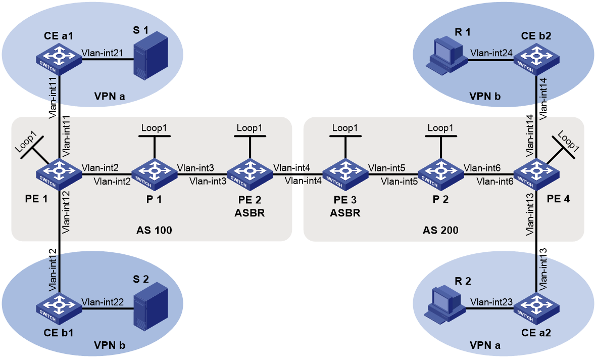
Table 4 Interface and IP address assignment
|
Device |
Interface |
IP address |
Device |
Interface |
IP address |
|
S 1 |
— |
12.1.1.100/24 |
R 1 |
— |
12.4.1.100/24 |
|
S 2 |
— |
12.2.1.100/24 |
R 2 |
— |
12.3.1.100/24 |
|
PE 1 |
Vlan-int2 |
10.1.1.1/24 |
PE 3 |
Vlan-int5 |
10.4.1.1/24 |
|
PE 1 |
Vlan-int11 |
11.1.1.1/24 |
PE 3 |
Vlan-int4 |
10.3.1.2/24 |
|
PE 1 |
Vlan-int12 |
11.2.1.1/24 |
PE 3 |
Loop1 |
3.3.3.3/32 |
|
PE 1 |
Loop1 |
1.1.1.1/32 |
PE 4 |
Vlan-int6 |
10.5.1.2/24 |
|
PE 2 |
Vlan-int3 |
10.2.1.2/24 |
PE 4 |
Vlan-int13 |
11.3.1.1/24 |
|
PE 2 |
Vlan-int4 |
10.3.1.1/24 |
PE 4 |
Vlan-int14 |
11.4.1.1/24 |
|
PE 2 |
Loop1 |
2.2.2.2/32 |
PE 4 |
Loop1 |
4.4.4.4/24 |
|
P 1 |
Vlan-int2 |
10.1.1.2/24 |
P 2 |
Vlan-int6 |
10.5.1.1/24 |
|
P 1 |
Vlan-int3 |
10.2.1.1/24 |
P 2 |
Vlan-int5 |
10.4.1.2/24 |
|
P 1 |
Loop1 |
5.5.5.5/32 |
P 2 |
Loop1 |
6.6.6.6/32 |
|
CE a1 |
Vlan-int21 |
12.1.1.1/24 |
CE b1 |
Vlan-int22 |
12.2.1.1/24 |
|
CE a1 |
Vlan-int11 |
11.1.1.2/24 |
CE b1 |
Vlan-int12 |
11.2.1.2/24 |
|
CE a2 |
Vlan-int23 |
12.3.1.1/24 |
CE b2 |
Vlan-int24 |
12.4.1.1/24 |
|
CE a2 |
Vlan-int13 |
11.3.1.2/24 |
CE b2 |
Vlan-int14 |
11.4.1.2/24 |
Procedure
|
|
IMPORTANT: By default, interfaces on the device are disabled (in ADM or Administratively Down state). To have an interface operate, you must use the undo shutdown command to enable that interface. |
1. Configure PE 1:
# Configure a global router ID, and enable IP multicast routing on the public network.
<PE1> system-view
[PE1] router id 1.1.1.1
[PE1] multicast routing
[PE1-mrib] quit
# Create service loopback group 1, and specify the multicast tunnel service for the group.
[PE1] service-loopback group 1 type multicast-tunnel
# Assign FortyGigE 1/0/4 to service loopback group 1. The interface does not belong to VLAN 2, VLAN 11, or VLAN 12.
[PE1] interface fortygige 1/0/4
[PE1-FortyGigE1/0/4] port service-loopback group 1
[PE1-FortyGigE1/0/4] quit
# Configure an LSR ID, and enable LDP globally.
[PE1] mpls lsr-id 1.1.1.1
[PE1] mpls ldp
[PE1-ldp] quit
# Create a VPN instance named a, and configure the RD and route targets for the VPN instance.
[PE1] ip vpn-instance a
[PE1-vpn-instance-a] route-distinguisher 100:1
[PE1-vpn-instance-a] vpn-target 100:1 export-extcommunity
[PE1-vpn-instance-a] vpn-target 100:1 import-extcommunity
[PE1-vpn-instance-a] quit
# Enable IP multicast routing for VPN instance a.
[PE1] multicast routing vpn-instance a
# Enable the RPF vector feature.
[PE1-mrib-a] rpf proxy vector
[PE1-mrib-a] quit
# Create an MDT-based MVPN for VPN instance a.
[PE1] multicast-vpn vpn-instance a mode mdt
# Create an MVPN IPv4 address family for VPN instance a.
[PE1-mvpn-a] address-family ipv4
# Specify the default-group, the MVPN source interface, and the data-group range for VPN instance a.
[PE1-mvpn-a-ipv4] default-group 232.1.1.1
[PE1-mvpn-a-ipv4] source loopback 1
[PE1-mvpn-a-ipv4] data-group 232.2.2.0 28
[PE1-mvpn-a-ipv4] quit
[PE1-mvpn-a] quit
# Create a VPN instance named b, and configure the RD and route targets for VPN instance.
[PE1] ip vpn-instance b
[PE1-vpn-instance-b] route-distinguisher 200:1
[PE1-vpn-instance-b] vpn-target 200:1 export-extcommunity
[PE1-vpn-instance-b] vpn-target 200:1 import-extcommunity
[PE1-vpn-instance-b] quit
# Enable IP multicast routing for VPN instance b.
[PE1] multicast routing vpn-instance b
# Enable the RPF vector feature.
[PE1-mrib-b] rpf proxy vector
[PE1-mrib-b] quit
# Create an MDT-based MVPN for VPN instance b.
[PE1] multicast-vpn vpn-instance b mode mdt
# Create an MVPN IPv4 address family for VPN instance b.
[PE1-mvpn-b] address-family ipv4
# Specify the default-group, the MVPN source interface, and the data-group range for VPN instance b.
[PE1-mvpn-b-ipv4] default-group 232.3.3.3
[PE1-mvpn-b-ivp4] source loopback 1
[PE1-mvpn-b-ivp4] data-group 232.4.4.0 28
[PE1-mvpn-b-ipv4] quit
[PE1-mvpn-b] quit
# Assign an IP address to VLAN-interface 2.
[PE1] interface vlan-interface 2
[PE1-Vlan-interface2] ip address 10.1.1.1 24
# Enable PIM-SM, MPLS, and IPv4 LDP on VLAN-interface 2.
[PE1-Vlan-interface2] pim sm
[PE1-Vlan-interface2] mpls enable
[PE1-Vlan-interface2] mpls ldp enable
[PE1-Vlan-interface2] quit
# Associate VLAN-interface 11 with VPN instance a.
[PE1] interface vlan-interface 11
[PE1-Vlan-interface11] ip binding vpn-instance a
# Assign an IP address to VLAN-interface 11, and enable PIM-SM on the interface.
[PE1-Vlan-interface11] ip address 11.1.1.1 24
[PE1-Vlan-interface11] pim sm
[PE1-Vlan-interface11] quit
# Associate VLAN-interface 12 with VPN instance b.
[PE1] interface vlan-interface 12
[PE1-Vlan-interface12] ip binding vpn-instance b
# Assign an IP address to VLAN-interface 12, and enable PIM-SM on the interface.
[PE1-Vlan-interface12] ip address 11.2.1.1 24
[PE1-Vlan-interface12] pim sm
[PE1-Vlan-interface12] quit
# Assign an IP address to Loopback 1, and enable PIM-SM on the interface.
[PE1] interface loopback 1
[PE1-LoopBack1] ip address 1.1.1.1 32
[PE1-LoopBack1] pim sm
[PE1-LoopBack1] quit
# Configure BGP.
[PE1] bgp 100
[PE1-bgp-default] peer 2.2.2.2 as-number 100
[PE1-bgp-default] peer 2.2.2.2 connect-interface loopback 1
[PE1–bgp-default] ip vpn-instance a
[PE1-bgp-default-a] address-family ipv4
[PE1-bgp-default-ipv4-a] import-route ospf 2
[PE1-bgp-default-ipv4-a] import-route direct
[PE1-bgp-default-ipv4-a] quit
[PE1-bgp-default-a] quit
[PE1–bgp-default] ip vpn-instance b
[PE1-bgp-default-b] address-family ipv4
[PE1-bgp-default-ipv4-b] import-route ospf 3
[PE1-bgp-default-ipv4-b] import-route direct
[PE1-bgp-default-ipv4-b] quit
[PE1-bgp-default-b] quit
[PE1–bgp-default] address-family vpnv4
[PE1–bgp-default-vpnv4] peer 2.2.2.2 enable
[PE1–bgp-default-vpnv4] quit
[PE1-bgp-default] address-family ipv4 mdt
[PE1-bgp-default-mdt] peer 2.2.2.2 enable
[PE1-bgp-default-mdt] quit
[PE1–bgp-default] quit
# Configure OSPF.
[PE1] ospf 1
[PE1-ospf-1] area 0.0.0.0
[PE1-ospf-1-area-0.0.0.0] network 1.1.1.1 0.0.0.0
[PE1-ospf-1-area-0.0.0.0] network 10.1.1.0 0.0.0.255
[PE1-ospf-1-area-0.0.0.0] quit
[PE1-ospf-1] quit
[PE1] ospf 2 vpn-instance a
[PE1-ospf-2] area 0.0.0.0
[PE1-ospf-2-area-0.0.0.0] network 11.1.1.0 0.0.0.255
[PE1-ospf-2-area-0.0.0.0] quit
[PE1-ospf-2] quit
[PE1] ospf 3 vpn-instance b
[PE1-ospf-3] area 0.0.0.0
[PE1-ospf-3-area-0.0.0.0] network 11.2.1.0 0.0.0.255
[PE1-ospf-3-area-0.0.0.0] quit
[PE1-ospf-3] quit
2. Configure PE 2:
# Configure a global router ID, and enable IP multicast routing on the public network.
<PE2> system-view
[PE2] router id 2.2.2.2
[PE2] multicast routing
[PE2-mrib] quit
# Configure an LSR ID, and enable LDP globally.
[PE2] mpls lsr-id 2.2.2.2
[PE2] mpls ldp
[PE2-ldp] quit
# Assign an IP address to VLAN-interface 3.
[PE2] interface vlan-interface 3
[PE2-Vlan-interface3] ip address 10.2.1.2 24
# Enable PIM-SM, MPLS, and IPv4 LDP on VLAN-interface 3.
[PE2-Vlan-interface3] pim sm
[PE2-Vlan-interface3] mpls enable
[PE2-Vlan-interface3] mpls ldp enable
[PE2-Vlan-interface3] quit
# Assign an IP address to VLAN-interface 4.
[PE2] interface vlan-interface 4
[PE2-Vlan-interface4] ip address 10.3.1.1 24
# Enable PIM-SM and MPLS on VLAN-interface 4.
[PE2-Vlan-interface4] pim sm
[PE2-Vlan-interface4] mpls enable
[PE2-Vlan-interface4] quit
# Assign an IP address to Loopback 1, and enable PIM-SM on the interface.
[PE2] interface loopback 1
[PE2-LoopBack1] ip address 2.2.2.2 32
[PE2-LoopBack1] pim sm
[PE2-LoopBack1] quit
# Configure BGP.
[PE2] bgp 100
[PE2-bgp-default] peer 1.1.1.1 as-number 100
[PE2-bgp-default] peer 1.1.1.1 connect-interface loopback 1
[PE2-bgp-default] peer 10.3.1.2 as-number 200
[PE2-bgp-default] address-family vpnv4
[PE2-bgp-default-vpnv4] undo policy vpn-target
[PE2-bgp-default-vpnv4] peer 1.1.1.1 enable
[PE2-bgp-default-vpnv4] peer 10.3.1.2 enable
[PE2-bgp-default-vpnv4] quit
[PE2-bgp-default] address-family ipv4 mdt
[PE2-bgp-default-mdt] peer 1.1.1.1 enable
[PE2-bgp-default-mdt] peer 10.3.1.2 enable
[PE2-bgp-default-mdt] quit
[PE2–bgp-default] quit
# Configure OSPF.
[PE2] ospf 1
[PE2-ospf-1] area 0.0.0.0
[PE2-ospf-1-area-0.0.0.0] network 2.2.2.2 0.0.0.0
[PE2-ospf-1-area-0.0.0.0] network 10.2.1.0 0.0.0.255
[PE2-ospf-1-area-0.0.0.0] quit
[PE2-ospf-1] quit
3. Configure PE 3:
# Configure a global router ID, and enable IP multicast routing on the public network.
<PE3> system-view
[PE3] router id 3.3.3.3
[PE3] multicast routing
[PE3-mrib] quit
# Configure an LSR ID, and enable LDP globally.
[PE3] mpls lsr-id 3.3.3.3
[PE3] mpls ldp
[PE3-ldp] quit
# Assign an IP address to VLAN-interface 5.
[PE3] interface vlan-interface 5
[PE3-Vlan-interface5] ip address 10.4.1.1 24
# Enable PIM-SM, MPLS, and IPv4 LDP on VLAN-interface 5.
[PE3-Vlan-interface5] pim sm
[PE3-Vlan-interface5] mpls enable
[PE3-Vlan-interface5] mpls ldp enable
[PE3-Vlan-interface5] quit
# Assign an IP address to VLAN-interface 4.
[PE3] interface vlan-interface 4
[PE3-Vlan-interface4] ip address 10.3.1.2 24
# Enable PIM-SM and MPLS on VLAN-interface 4.
[PE3-Vlan-interface4] pim sm
[PE3-Vlan-interface4] mpls enable
[PE3-Vlan-interface4] quit
# Assign an IP address to Loopback 1, and enable PIM-SM on the interface.
[PE3] interface loopback 1
[PE3-LoopBack1] ip address 3.3.3.3 32
[PE3-LoopBack1] pim sm
[PE3-LoopBack1] quit
# Configure BGP.
[PE3] bgp 200
[PE3-bgp-default] peer 4.4.4.4 as-number 200
[PE3-bgp-default] peer 4.4.4.4 connect-interface loopback 1
[PE3-bgp-default] peer 10.3.1.1 as-number 100
[PE3-bgp-default] address-family vpnv4
[PE3-bgp-default-vpnv4] undo policy vpn-target
[PE3-bgp-default-vpnv4] peer 4.4.4.4 enable
[PE3-bgp-default-vpnv4] peer 10.3.1.1 enable
[PE3-bgp-default-vpnv4] quit
[PE3-bgp-default] address-family ipv4 mdt
[PE3-bgp-default-mdt] peer 4.4.4.4 enable
[PE3-bgp-default-mdt] peer 10.3.1.1 enable
[PE3-bgp-default-mdt] quit
[PE3–bgp-default] quit
# Configure OSPF.
[PE3] ospf 1
[PE3-ospf-1] area 0.0.0.0
[PE3-ospf-1-area-0.0.0.0] network 3.3.3.3 0.0.0.0
[PE3-ospf-1-area-0.0.0.0] network 10.4.1.0 0.0.0.255
[PE3-ospf-1-area-0.0.0.0] quit
[PE3-ospf-1] quit
4. Configure PE 4:
# Configure a global router ID, and enable IP multicast routing on the public network.
<PE4> system-view
[PE4] router id 4.4.4.4
[PE4] multicast routing
[PE4-mrib] quit
# Create service loopback group 1, and specify the multicast tunnel service for the group.
[PE4] service-loopback group 1 type multicast-tunnel
# Assign FortyGigE 1/0/4 to service loopback group 1. The interface does not belong to VLAN 6, VLAN 13, or VLAN 14.
[PE4] interface fortygige 1/0/4
[PE4-FortyGigE1/0/4] port service-loopback group 1
[PE4-FortyGigE1/0/4] quit
# Configure an LSR ID, and enable LDP globally.
[PE4] mpls lsr-id 4.4.4.4
[PE4] mpls ldp
[PE4-ldp] quit
# Create a VPN instance named a, and configure the RD and route targets for the VPN instance.
[PE4] ip vpn-instance a
[PE4-vpn-instance-a] route-distinguisher 100:1
[PE4-vpn-instance-a] vpn-target 100:1 export-extcommunity
[PE4-vpn-instance-a] vpn-target 100:1 import-extcommunity
[PE4-vpn-instance-a] quit
# Enable IP multicast routing for VPN instance a.
[PE4] multicast routing vpn-instance a
# Enable the RPF vector feature.
[PE4-mrib-a] rpf proxy vector
[PE4-mrib-a] quit
# Create an MDT-based MVPN for VPN instance a.
[PE4] multicast-vpn vpn-instance a mode mdt
# Create an MVPN IPv4 address family for VPN instance a.
[PE4-mvpn-a] address-family ipv4
# Specify the default-group, the MVPN source interface, and the data-group range for VPN instance a.
[PE4-mvpn-a-ipv4] default-group 232.1.1.1
[PE4-mvpn-a-ipv4] source loopback 1
[PE4-mvpn-a-ipv4] data-group 232.2.2.0 28
[PE4-mvpn-a-ipv4] quit
[PE4-mvpn-a] quit
# Create a VPN instance named b, and configure the RD and route targets for the VPN instance.
[PE4] ip vpn-instance b
[PE4-vpn-instance-b] route-distinguisher 200:1
[PE4-vpn-instance-b] vpn-target 200:1 export-extcommunity
[PE4-vpn-instance-b] vpn-target 200:1 import-extcommunity
[PE4-vpn-instance-b] quit
# Enable IP multicast routing for VPN instance b.
[PE4] multicast routing vpn-instance b
# Enable the RPF vector feature.
[PE4-mrib-b] rpf proxy vector
[PE4-mrib-b] quit
# Create an MDT-based MVPN for VPN instance b.
[PE4] multicast-vpn vpn-instance b mode mdt
# Create an MVPN IPv4 address family for VPN instance b.
[PE4-mvpn-b] address-family ipv4
# Specify the default-group, the MVPN source interface, and the data-group range for VPN instance b.
[PE4-mvpn-b-ipv4] default-group 232.3.3.3
[PE4-mvpn-b-ipv4] source loopback 1
[PE4-mvpn-b-ipv4] data-group 232.4.4.0 28
[PE4-mvpn-b-ipv4] quit
[PE4-mvpn-b] quit
# Assign an IP address to VLAN-interface 6.
[PE4] interface vlan-interface 6
[PE4-Vlan-interface6] ip address 10.5.1.2 24
# Enable PIM-SM, MPLS, and IPv4 LDP on VLAN-interface 6.
[PE4-Vlan-interface6] pim sm
[PE4-Vlan-interface6] mpls enable
[PE4-Vlan-interface6] mpls ldp enable
[PE4-Vlan-interface6] quit
# Associate VLAN-interface 13 with VPN instance a.
[PE4] interface vlan-interface 13
[PE4-Vlan-interface13] ip binding vpn-instance a
# Assign an IP address to VLAN-interface 13, and enable PIM-SM on the interface.
[PE4-Vlan-interface13] ip address 11.3.1.1 24
[PE4-Vlan-interface13] pim sm
[PE4-Vlan-interface13] quit
# Associate VLAN-interface 14 with VPN instance b.
[PE4] interface vlan-interface 14
[PE4-Vlan-interface14] ip binding vpn-instance b
# Assign an IP address to VLAN-interface 14, and enable PIM-SM on the interface.
[PE4-Vlan-interface14] ip address 11.4.1.1 24
[PE4-Vlan-interface14] pim sm
[PE4-Vlan-interface14] quit
# Assign an IP address to Loopback 1, and enable PIM-SM on the interface.
[PE4] interface loopback 1
[PE4-LoopBack1] ip address 4.4.4.4 32
[PE4-LoopBack1] pim sm
[PE4-LoopBack1] quit
# Configure BGP.
[PE4] bgp 200
[PE4-bgp-default] peer 3.3.3.3 as-number 200
[PE4-bgp-default] peer 3.3.3.3 connect-interface loopback 1
[PE4–bgp-default] ip vpn-instance a
[PE4-bgp-default-a] address-family ipv4
[PE4-bgp-default-ipv4-a] import-route ospf 2
[PE4-bgp-default-ipv4-a] import-route direct
[PE4-bgp-default-ipv4-a] quit
[PE4-bgp-default-a] quit
[PE4–bgp-default] ip vpn-instance b
[PE4-bgp-default-b] address-family ipv4
[PE4-bgp-default-ipv4-b] import-route ospf 3
[PE4-bgp-default-ipv4-b] import-route direct
[PE4-bgp-default-ipv4-b] quit
[PE4-bgp-default-b] quit
[PE4–bgp-default] address-family vpnv4
[PE4–bgp-default-vpnv4] peer 3.3.3.3 enable
[PE4–bgp-default-vpnv4] quit
[PE4-bgp-default] address-family ipv4 mdt
[PE4-bgp-default-mdt] peer 3.3.3.3 enable
[PE4-bgp-default-mdt] quit
[PE4–bgp-default] quit
# Configure OSPF.
[PE4] ospf 1
[PE4-ospf-1] area 0.0.0.0
[PE4-ospf-1-area-0.0.0.0] network 4.4.4.4 0.0.0.0
[PE4-ospf-1-area-0.0.0.0] network 10.5.1.0 0.0.0.255
[PE4-ospf-1-area-0.0.0.0] quit
[PE4-ospf-1] quit
[PE4] ospf 2 vpn-instance a
[PE4-ospf-2] area 0.0.0.0
[PE4-ospf-2-area-0.0.0.0] network 11.3.1.0 0.0.0.255
[PE4-ospf-2-area-0.0.0.0] quit
[PE4-ospf-2] quit
[PE4] ospf 3 vpn-instance b
[PE4-ospf-3] area 0.0.0.0
[PE4-ospf-3-area-0.0.0.0] network 11.4.1.0 0.0.0.255
[PE4-ospf-3-area-0.0.0.0] quit
[PE4-ospf-3] quit
5. Configure P 1:
# Enable IP multicast routing on the public network.
<P1> system-view
[P1] multicast routing
[P1-mrib] quit
# Configure an LSR ID, and enable LDP globally.
[P1] mpls lsr-id 5.5.5.5
[P1] mpls ldp
[P1-ldp] quit
# Assign an IP address to VLAN-interface 2.
[P1] interface vlan-interface 2
[P1-Vlan-interface2] ip address 10.1.1.2 24
# Enable PIM-SM, MPLS, and IPv4 LDP on VLAN-interface 2.
[P1-Vlan-interface2] pim sm
[P1-Vlan-interface2] mpls enable
[P1-Vlan-interface2] mpls ldp enable
[P1-Vlan-interface2] quit
# Assign an IP address to VLAN-interface 3.
[P1] interface vlan-interface 3
[P1-Vlan-interface3] ip address 10.2.1.1 24
# Enable PIM-SM, MPLS, and IPv4 LDP on VLAN-interface 3.
[P1-Vlan-interface3] pim sm
[P1-Vlan-interface3] mpls enable
[P1-Vlan-interface3] mpls ldp enable
[P1-Vlan-interface3] quit
# Assign an IP address to Loopback 1, and enable PIM-SM on the interface.
[P1] interface loopback 1
[P1-LoopBack1] ip address 5.5.5.5 32
[P1-LoopBack1] pim sm
[P1-LoopBack1] quit
# Configure OSPF.
[P1] ospf 1
[P1-ospf-1] area 0.0.0.0
[P1-ospf-1-area-0.0.0.0] network 5.5.5.5 0.0.0.0
[P1-ospf-1-area-0.0.0.0] network 10.1.1.0 0.0.0.255
[P1-ospf-1-area-0.0.0.0] network 10.2.1.0 0.0.0.255
6. Configure P 2:
# Enable IP multicast routing on the public network.
<P2> system-view
[P2] multicast routing
[P2-mrib] quit
# Configure an LSR ID, and enable LDP globally.
[P2] mpls lsr-id 6.6.6.6
[P2] mpls ldp
[P2-ldp] quit
# Assign an IP address to VLAN-interface 6.
[P2] interface vlan-interface 6
[P2-Vlan-interface6] ip address 10.5.1.1 24
# Enable PIM-SM, MPLS, and IPv4 LDP on VLAN-interface 6.
[P2-Vlan-interface6] pim sm
[P2-Vlan-interface6] mpls enable
[P2-Vlan-interface6] mpls ldp enable
[P2-Vlan-interface6] quit
# Assign an IP address to VLAN-interface 5.
[P2] interface vlan-interface 5
[P2-Vlan-interface5] ip address 10.4.1.2 24
# Enable PIM-SM, MPLS, and IPv4 LDP on VLAN-interface 5.
[P2-Vlan-interface5] pim sm
[P2-Vlan-interface5] mpls enable
[P2-Vlan-interface5] mpls ldp enable
[P2-Vlan-interface5] quit
# Assign an IP address to Loopback 1, and enable PIM-SM on the interface.
[P2] interface loopback 1
[P2-LoopBack1] ip address 6.6.6.6 32
[P2-LoopBack1] pim sm
[P2-LoopBack1] quit
# Configure OSPF.
[P2] ospf 1
[P2-ospf-1] area 0.0.0.0
[P2-ospf-1-area-0.0.0.0] network 6.6.6.6 0.0.0.0
[P2-ospf-1-area-0.0.0.0] network 10.4.1.0 0.0.0.255
[P2-ospf-1-area-0.0.0.0] network 10.5.1.0 0.0.0.255
7. Configure CE a1:
# Enable IP multicast routing.
<CEa1> system-view
[CEa1] multicast routing
[CEa1-mrib] quit
# Assign an IP address to VLAN-interface 21, and enable PIM-SM on the interface.
[CEa1] interface vlan-interface 21
[CEa1-Vlan-interface21] ip address 12.1.1.1 24
[CEa1-Vlan-interface21] pim sm
[CEa1-Vlan-interface21] quit
# Assign an IP address to VLAN-interface 11, and enable PIM-SM on the interface.
[CEa1] interface vlan-interface 11
[CEa1-Vlan-interface11] ip address 11.1.1.2 24
[CEa1-Vlan-interface11] pim sm
[CEa1-Vlan-interface11] quit
# Configure VLAN-interface 11 as a C-BSR and a C-RP.
[CEa1] pim
[CEa1-pim] c-bsr 11.1.1.2
[CEa1-pim] c-rp 11.1.1.2
[CEa1-pim] quit
# Configure OSPF.
[CEa1] ospf 1
[CEa1-ospf-1] area 0.0.0.0
[CEa1-ospf-1-area-0.0.0.0] network 12.1.1.0 0.0.0.255
[CEa1-ospf-1-area-0.0.0.0] network 11.1.1.0 0.0.0.255
[CEa1-ospf-1-area-0.0.0.0] quit
[CEa1-ospf-1] quit
8. Configure CE b1:
# Enable IP multicast routing.
<CEb1> system-view
[CEb1] multicast routing
[CEb1-mrib] quit
# Assign an IP address to VLAN-interface 22, and enable PIM-SM on the interface.
[CEb1] interface vlan-interface 22
[CEb1-Vlan-interface22] ip address 12.2.1.1 24
[CEb1-Vlan-interface22] pim sm
[CEb1-Vlan-interface22] quit
# Assign an IP address to VLAN-interface 12, and enable PIM-SM on the interface.
[CEb1] interface vlan-interface 12
[CEb1-Vlan-interface12] ip address 11.2.1.2 24
[CEb1-Vlan-interface12] pim sm
[CEb1-Vlan-interface12] quit
# Configure VLAN-interface 12 as a C-BSR and a C-RP.
[CEb1] pim
[CEb1-pim] c-bsr 11.2.1.2 24
[CEb1-pim] c-rp 11.2.1.2 24
[CEb1-pim] quit
# Configure OSPF.
[CEb1] ospf 1
[CEb1-ospf-1] area 0.0.0.0
[CEb1-ospf-1-area-0.0.0.0] network 12.2.1.0 0.0.0.255
[CEb1-ospf-1-area-0.0.0.0] network 11.2.1.0 0.0.0.255
[CEb1-ospf-1-area-0.0.0.0] quit
[CEb1-ospf-1] quit
9. Configure CE a2:
# Enable IP multicast routing.
<CEa2> system-view
[CEa2] multicast routing
[CEa2-mrib] quit
# Assign an IP address to VLAN-interface 23, and enable IGMP on the interface.
[CEa2] interface vlan-interface 23
[CEa2-Vlan-interface23] ip address 12.3.1.1 24
[CEa2-Vlan-interface23] igmp enable
[CEa2-Vlan-interface23] quit
# Assign an IP address to VLAN-interface 13, and enable PIM-SM on the interface.
[CEa2] interface vlan-interface 13
[CEa2-Vlan-interface13] ip address 11.3.1.2 24
[CEa2-Vlan-interface13] pim sm
[CEa2-Vlan-interface13] quit
# Configure OSPF.
[CEa2] ospf 1
[CEa2-ospf-1] area 0.0.0.0
[CEa2-ospf-1-area-0.0.0.0] network 12.3.1.0 0.0.0.255
[CEa2-ospf-1-area-0.0.0.0] network 11.3.1.0 0.0.0.255
[CEa2-ospf-1-area-0.0.0.0] quit
[CEa2-ospf-1] quit
10. Configure CE b2:
# Enable IP multicast routing.
<CEb2> system-view
[CEb2] multicast routing
[CEb2-mrib] quit
# Assign an IP address to VLAN-interface 24, and enable IGMP on the interface.
[CEb2] interface vlan-interface 24
[CEb2-Vlan-interface24] ip address 12.4.1.1 24
[CEb2-Vlan-interface24] igmp enable
[CEb2-Vlan-interface24] quit
# Assign an IP address to VLAN-interface 14, and enable PIM-SM on the interface.
[CEb2] interface vlan-interface 14
[CEb2-Vlan-interface14] ip address 11.4.1.2 24
[CEb2-Vlan-interface14] pim sm
[CEb2-Vlan-interface14] quit
# Configure OSPF.
[CEb2] ospf 1
[CEb2-ospf-1] area 0.0.0.0
[CEb2-ospf-1-area-0.0.0.0] network 12.4.1.0 0.0.0.255
[CEb2-ospf-1-area-0.0.0.0] network 11.4.1.0 0.0.0.255
[CEb2-ospf-1-area-0.0.0.0] quit
[CEb2-ospf-1] quit
Verifying the configuration
# Display information about the local default-group for IPv4 multicast transmission in each VPN instance on PE 1.
[PE1] display multicast-vpn default-group local
MVPN local default-group information:
Group address Source address Interface VPN instance
232.1.1.1 1.1.1.1 MTunnel0 a
232.3.3.3 1.1.1.1 MTunnel1 b
# Display information about the remote default-group group for IPv4 multicast transmission in each VPN instance on PE 1.
[PE1] display multicast-vpn default-group remote
MVPN remote default-group information:
Group address Source address Next hop VPN instance
232.1.1.1 4.4.4.4 2.2.2.2 a
232.3.3.3 4.4.4.4 2.2.2.2 b
# Display information about the local default-group for IPv4 multicast transmission in each VPN instance on PE 4.
[PE4] display multicast-vpn default-group local
MVPN local default-group information:
Group address Source address Interface VPN instance
232.1.1.1 4.4.4.4 MTunnel0 a
233.3.3.3 4.4.4.4 MTunnel1 b
# Display information about the remote default-group for IPv4 multicast transmission in each VPN instance on PE 4.
[PE4] display multicast-vpn default-group remote
MVPN remote default-group information:
Group address Source address Next hop VPN instance
232.1.1.1 1.1.1.1 3.3.3.3 a
Example: Configuring MDT-based MVPN inter-AS option C
Network configuration
As shown in Figure 17, configure MDT-based MVPN inter-AS option C to meet the following requirements:
|
Item |
Network configuration |
|
Multicast sources and receivers |
· In VPN instance a, S 1 is a multicast source, and R 2 is a receiver. · In VPN instance b, S 2 is a multicast source, and R 1 is a receiver. · For VPN instance a, the default-group is 239.1.1.1, and the data-group range is 225.1.1.0 to 225.1.1.15. · For VPN instance b, the default-group is 239.4.4.4, and the data-group range is 225.4.4.0 to 225.4.4.15. |
|
VPN instances to which PEs belong |
· PE 1: VLAN-interface 11 belongs to VPN instance b. VLAN-interface 12 belongs to VPN instance a. VLAN-interface 2 and Loopback 1 belong to the public network instance. · PE 2: VLAN-interface 2, VLAN-interface 3, Loopback 1, and Loopback 2 belong to the public network instance. · PE 3: VLAN-interface 3, VLAN-interface 4, Loopback 1, and Loopback 2 belong to the public network instance. · PE 4: VLAN-interface 13 belongs to VPN instance a. VLAN-interface 14 belongs to VPN instance b. VLAN-interface 4 and Loopback 1 belong to the public network instance. |
|
Unicast routing protocols and MPLS |
· Configure OSPF separately in AS 100 and AS 200, and configure OSPF between the PEs and CEs. · Establish BGP peer connections between PE 1, PE 2, PE 3, and PE 4 on their respective Loopback 1. · Configure MPLS separately in AS 100 and AS 200. |
|
IP multicast routing |
· Enable IP multicast routing on the public network on PE 1, PE 2, PE 3, and PE 4. · Enable IP multicast routing for VPN instance a on PE 1 and PE 4. · Enable IP multicast routing for VPN instance b on PE 1 and PE 4. · Enable IP multicast routing on CE a1, CE a2, CE b1, and CE b2. |
|
IGMPv2 |
· Enable IGMPv2 on VLAN-interface 30 of CE a2. · Enable IGMPv2 on VLAN-interface 40 of CE b2. |
|
PIM-SM |
Enable PIM-SM on the public network and for VPN instances a and b: · Enable PIM-SM on all public network interfaces of PE 2 and PE 3. · Enable PIM-SM on all public and private network interfaces of PE 1 and PE 4. · Enable PIM-SM on all interfaces that do not have attached receiver hosts of CE a1, CE a2, CE b1, and CE b2. · Configure Loopback 2 of PE 2 and PE 3 as a C-BSR and a C-RP for their own AS to provide services for all multicast groups. · Configure Loopback 0 of CE a1 as a C-BSR and a C-RP for VPN instance a to provide services for all multicast groups. · Configure Loopback 0 of CE b1 as a C-BSR and a C-RP for VPN instance b to provide services for all multicast groups. |
|
MSDP |
Establish an MSDP peering relationship between PE 2 and PE 3 on their Loopback 1. |
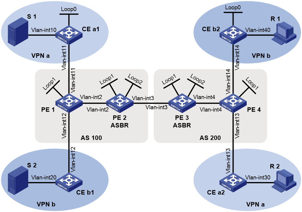
Table 5 Interface and IP address assignment
|
Device |
Interface |
IP address |
Device |
Interface |
IP address |
|
S 1 |
— |
10.11.5.2/24 |
R 1 |
— |
10.11.8.2/24 |
|
S 2 |
— |
10.11.6.2/24 |
R 2 |
— |
10.11.7.2/24 |
|
PE 1 |
Vlan-int2 |
10.10.1.1/24 |
PE 3 |
Vlan-int4 |
10.10.2.1/24 |
|
PE 1 |
Vlan-int11 |
10.11.1.1/24 |
PE 3 |
Vlan-int3 |
192.168.1.2/24 |
|
PE 1 |
Vlan-int12 |
10.11.2.1/24 |
PE 3 |
Loop1 |
1.1.1.3/32 |
|
PE 1 |
Loop1 |
1.1.1.1/32 |
PE 3 |
Loop2 |
22.22.22.22/32 |
|
PE 2 |
Vlan-int2 |
10.10.1.2/24 |
PE 4 |
Vlan-int4 |
10.10.2.2/24 |
|
PE 2 |
Vlan-int3 |
192.168.1.1/24 |
PE 4 |
Vlan-int13 |
10.11.3.1/24 |
|
PE 2 |
Loop1 |
1.1.1.2/32 |
PE 4 |
Vlan-int14 |
10.11.4.1/32 |
|
PE 2 |
Loop2 |
11.11.11.11/32 |
PE 4 |
Loop1 |
1.1.1.4/32 |
|
CE a1 |
Vlan-int10 |
10.11.5.1/24 |
CE b1 |
Vlan-int20 |
10.11.6.1/24 |
|
CE a1 |
Vlan-int11 |
10.11.1.2/24 |
CE b1 |
Vlan-int12 |
10.11.2.2/24 |
|
CE a1 |
Loop0 |
2.2.2.2/32 |
CE b2 |
Vlan-int40 |
10.11.8.1/24 |
|
CE a2 |
Vlan-int30 |
10.11.7.1/24 |
CE b2 |
Vlan-int14 |
10.11.4.2/24 |
|
CE a2 |
Vlan-int13 |
10.11.3.2/24 |
CE b2 |
Loop0 |
3.3.3.3/32 |
Procedure
|
|
IMPORTANT: By default, interfaces on the device are disabled (in ADM or Administratively Down state). To have an interface operate, you must use the undo shutdown command to enable that interface. |
1. Configure PE 1:
# Configure a global router ID, and enable IP multicast routing on the public network.
<PE1> system-view
[PE1] router id 1.1.1.1
[PE1] multicast routing
[PE1-mrib] quit
# Create service loopback group 1, and specify the multicast tunnel service for the group.
[PE1] service-loopback group 1 type multicast-tunnel
# Assign FortyGigE 1/0/4 to service loopback group 1. The interface does not belong to VLAN 2, VLAN 11, or VLAN 12.
[PE1] interface fortygige 1/0/4
[PE1-FortyGigE1/0/4] port service-loopback group 1
[PE1-FortyGigE1/0/4] quit
# Configure an LSR ID, and enable LDP globally.
[PE1] mpls lsr-id 1.1.1.1
[PE1] mpls ldp
[PE1-ldp] quit
# Create a VPN instance named a, and configure an RD and route targets for the VPN instance.
[PE1] ip vpn-instance a
[PE1-vpn-instance-a] route-distinguisher 100:1
[PE1-vpn-instance-a] vpn-target 100:1 export-extcommunity
[PE1-vpn-instance-a] vpn-target 100:1 import-extcommunity
[PE1-vpn-instance-a] quit
# Enable IP multicast routing for VPN instance a.
[PE1] multicast routing vpn-instance a
[PE1-mrib-a] quit
# Create an MDT-based MVPN for VPN instance a.
[PE1] multicast-vpn vpn-instance a mode mdt
# Create an MVPN IPv4 address family for VPN instance a.
[PE1-mvpn-a] address-family ipv4
# Specify the default-group, the MVPN source interface, and the data-group range for VPN instance a.
[PE1-mvpn-a-ipv4] default-group 239.1.1.1
[PE1-mvpn-a-ipv4] source loopback 1
[PE1-mvpn-a-ipv4] data-group 225.1.1.0 28
[PE1-mvpn-a-ipv4] quit
[PE1-mvpn-a] quit
# Create a VPN instance named b, and configure an RD and route targets for the VPN instance.
[PE1] ip vpn-instance b
[PE1-vpn-instance-b] route-distinguisher 200:1
[PE1-vpn-instance-b] vpn-target 200:1 export-extcommunity
[PE1-vpn-instance-b] vpn-target 200:1 import-extcommunity
[PE1-vpn-instance-b] quit
# Enable IP multicast routing for VPN instance b.
[PE1] multicast routing vpn-instance b
[PE1-mrib-b] quit
# Create an MDT-based MVPN for VPN instance b.
[PE1] multicast-vpn vpn-instance b mode mdt
# Create an MVPN IPv4 address family for VPN instance b.
[PE1-mvpn-b] address-family ipv4
# Specify the default-group, the MVPN source interface, and the data-group range for VPN instance b.
[PE1-mvpn-b-ipv4] default-group 239.4.4.4
[PE1-mvpn-b-ipv4] source loopback 1
[PE1-mvpn-b-ivp4] data-group 225.4.4.0 28
[PE1-mvpn-b-ipv4] quit
[PE1-mvpn-b] quit
# Assign an IP address to VLAN-interface 2.
[PE1] interface vlan-interface 2
[PE1-Vlan-interface2] ip address 10.10.1.1 24
# Enable PIM-SM, MPLS, and IPv4 LDP on VLAN-interface 2.
[PE1-Vlan-interface2] pim sm
[PE1-Vlan-interface2] mpls enable
[PE1-Vlan-interface2] mpls ldp enable
[PE1-Vlan-interface2] quit
# Associate VLAN-interface 11 with VPN instance a.
[PE1] interface vlan-interface 11
[PE1-Vlan-interface11] ip binding vpn-instance a
# Assign an IP address to VLAN-interface 11, and enable PIM-SM on the interface.
[PE1-Vlan-interface11] ip address 10.11.1.1 24
[PE1-Vlan-interface11] pim sm
[PE1-Vlan-interface11] quit
# Associate VLAN-interface 12 with VPN instance b.
[PE1] interface vlan-interface 12
[PE1-Vlan-interface12] ip binding vpn-instance b
# Assign an IP address to VLAN-interface 12, and enable PIM-SM on the interface.
[PE1-Vlan-interface12] ip address 10.11.2.1 24
[PE1-Vlan-interface12] pim sm
[PE1-Vlan-interface12] quit
# Assign an IP address to Loopback 1, and enable PIM-SM on the interface.
[PE1] interface loopback 1
[PE1-LoopBack1] ip address 1.1.1.1 32
[PE1-LoopBack1] pim sm
[PE1-LoopBack1] quit
# Configure BGP.
[PE1] bgp 100
[PE1-bgp-default] group pe1-pe2 internal
[PE1-bgp-default] peer pe1-pe2 connect-interface loopback 1
[PE1-bgp-default] peer 1.1.1.2 group pe1-pe2
[PE1-bgp-default] group pe1-pe4 external
[PE1-bgp-default] peer pe1-pe4 as-number 200
[PE1-bgp-default] peer pe1-pe4 ebgp-max-hop 255
[PE1-bgp-default] peer pe1-pe4 connect-interface loopback 1
[PE1-bgp-default] peer 1.1.1.4 group pe1-pe4
[PE1–bgp-default] ip vpn-instance a
[PE1-bgp-default-a] address-family ipv4
[PE1-bgp-default-ipv4-a] import-route ospf 2
[PE1-bgp-default-ipv4-a] import-route direct
[PE1-bgp-default-ipv4-a] quit
[PE1-bgp-default-a] quit
[PE1–bgp-default] ip vpn-instance b
[PE1-bgp-default-b] address-family ipv4
[PE1-bgp-default-ipv4-b] import-route ospf 3
[PE1-bgp-default-ipv4-b] import-route direct
[PE1-bgp-default-ipv4-b] quit
[PE1-bgp-default-b] quit
[PE1–bgp-default] address-family ipv4
[PE1-bgp-default-ipv4] peer pe1-pe2 enable
[PE1-bgp-default-ipv4] peer pe1-pe2 label-route-capability
[PE1-bgp-default-ipv4] quit
[PE1–bgp-default] address-family vpnv4
[PE1–bgp-default-vpnv4] peer pe1-pe4 enable
[PE1–bgp-default-vpnv4] quit
[PE1–bgp-default] quit
# Configure OSPF.
[PE1] ospf 1
[PE1-ospf-1] area 0.0.0.0
[PE1-ospf-1-area-0.0.0.0] network 1.1.1.1 0.0.0.0
[PE1-ospf-1-area-0.0.0.0] network 10.10.1.0 0.0.0.255
[PE1-ospf-1-area-0.0.0.0] quit
[PE1-ospf-1] quit
[PE1] ospf 2 vpn-instance a
[PE1-ospf-2] import-route bgp
[PE1-ospf-2] area 0.0.0.0
[PE1-ospf-2-area-0.0.0.0] network 10.11.1.0 0.0.0.255
[PE1-ospf-2-area-0.0.0.0] quit
[PE1-ospf-2] quit
[PE1] ospf 3 vpn-instance b
[PE1-ospf-3] import-route bgp
[PE1-ospf-3] area 0.0.0.0
[PE1-ospf-3-area-0.0.0.0] network 10.11.2.0 0.0.0.255
[PE1-ospf-3-area-0.0.0.0] quit
[PE1-ospf-3] quit
2. Configure PE 2:
# Configure a global router ID, and enable IP multicast routing on the public network.
<PE2> system-view
[PE2] router id 1.1.1.2
[PE2] multicast routing
[PE2-mrib] quit
# Configure an LSR ID, and enable LDP globally.
[PE2] mpls lsr-id 1.1.1.2
[PE2] mpls ldp
[PE2-ldp] quit
# Assign an IP address to VLAN-interface 2.
[PE2] interface vlan-interface 2
[PE2-Vlan-interface2] ip address 10.10.1.2 24
# Enable PIM-SM, MPLS, and IPv4 LDP on VLAN-interface 2.
[PE2-Vlan-interface2] pim sm
[PE2-Vlan-interface2] mpls enable
[PE2-Vlan-interface2] mpls ldp enable
[PE2-Vlan-interface2] quit
# Assign an IP address to VLAN-interface 3.
[PE2] interface vlan-interface 3
[PE2-Vlan-interface3] ip address 192.168.1.1 24
# Enable PIM-SM and MPLS on VLAN-interface 3.
[PE2-Vlan-interface3] pim sm
[PE2-Vlan-interface3] mpls enable
[PE2-Vlan-interface3] quit
# Assign an IP address to Loopback 1, and enable PIM-SM on the interface.
[PE2] interface loopback 1
[PE2-LoopBack1] ip address 1.1.1.2 32
[PE2-LoopBack1] pim sm
[PE2-LoopBack1] quit
# Assign an IP address to Loopback 2, and enable PIM-SM on the interface.
[PE2] interface loopback 2
[PE2-LoopBack2] ip address 11.11.11.11 32
[PE2-LoopBack2] pim sm
[PE2-LoopBack2] quit
# Configure Loopback 2 as a C-BSR and a C-RP.
[PE2] pim
[PE2-pim] c-bsr 11.11.11.11
[PE2-pim] c-rp 11.11.11.11
[PE2-pim] quit
# Configure VLAN-interface 3 as a PIM-SM domain border.
[PE2] interface vlan-interface 3
[PE2-Vlan-interface3] pim bsr-boundary
[PE2-Vlan-interface3] quit
# Establish an MSDP peering relationship.
[PE2] msdp
[PE2-msdp] encap-data-enable
[PE2-msdp] peer 1.1.1.3 connect-interface loopback 1
# Configure a static route.
[PE2] ip route-static 1.1.1.3 32 vlan-interface 3 192.168.1.2
# Configure BGP.
[PE2] bgp 100
[PE2-bgp-default] group pe2-pe1 internal
[PE2-bgp-default] peer pe2-pe1 connect-interface loopback 1
[PE2-bgp-default] peer 1.1.1.1 group pe2-pe1
[PE2-bgp-default] group pe2-pe3 external
[PE2-bgp-default] peer pe2-pe3 as-number 200
[PE2-bgp-default] peer 192.168.1.2 group pe2-pe3
[PE2-bgp-default] address-family ipv4
[PE2-bgp-default-ipv4] peer pe2-pe1 enable
[PE2-bgp-default-ipv4] peer pe2-pe1 route-policy map2 export
[PE2-bgp-default-ipv4] peer pe2-pe1 label-route-capability
[PE2-bgp-default-ipv4] peer pe2-pe3 enable
[PE2-bgp-default-ipv4] peer pe2-pe3 route-policy map1 export
[PE2-bgp-default-ipv4] peer pe2-pe3 label-route-capability
[PE2-bgp-default-ipv4] import-route ospf 1
[PE2-bgp-default-ipv4] quit
[PE2–bgp-default] quit
# Configure OSPF.
[PE2] ospf 1
[PE2-ospf-1] area 0.0.0.0
[PE2-ospf-1-area-0.0.0.0] network 1.1.1.2 0.0.0.0
[PE2-ospf-1-area-0.0.0.0] network 11.11.11.11 0.0.0.0
[PE2-ospf-1-area-0.0.0.0] network 10.10.1.0 0.0.0.255
[PE2-ospf-1-area-0.0.0.0] quit
[PE2-ospf-1] quit
3. Configure PE 3:
# Configure a global router ID, and enable IP multicast routing on the public network.
<PE3> system-view
[PE3] router id 1.1.1.3
[PE3] multicast routing
[PE3-mrib] quit
# Configure an LSR ID, and enable LDP globally.
[PE3] mpls lsr-id 1.1.1.3
[PE3] mpls ldp
[PE3-ldp] quit
# Assign an IP address to VLAN-interface 4.
[PE3] interface vlan-interface 4
[PE3-Vlan-interface4] ip address 10.10.2.1 24
# Enable PIM-SM, MPLS, and IPv4 LDP on VLAN-interface 4.
[PE3-Vlan-interface4] pim sm
[PE3-Vlan-interface4] mpls enable
[PE3-Vlan-interface4] mpls ldp enable
[PE3-Vlan-interface4] quit
# Assign an IP address to VLAN-interface 3.
[PE3] interface vlan-interface 3
[PE3-Vlan-interface3] ip address 192.168.1.2 24
# Enable PIM-SM and MPLS on VLAN-interface 3.
[PE3-Vlan-interface3] pim sm
[PE3-Vlan-interface3] mpls enable
[PE3-Vlan-interface3] quit
# Assign an IP address to Loopback 1, and enable PIM-SM on the interface.
[PE3] interface loopback 1
[PE3-LoopBack1] ip address 1.1.1.3 32
[PE3-LoopBack1] pim sm
[PE3-LoopBack1] quit
# Assign an IP address to Loopback 2, and enable PIM-SM on the interface.
[PE3] interface loopback 2
[PE3-LoopBack2] ip address 22.22.22.22 32
[PE3-LoopBack2] pim sm
[PE3-LoopBack2] quit
# Configure Loopback 2 as a C-BSR and a C-RP.
[PE3] pim
[PE3-pim] c-bsr 22.22.22.22
[PE3-pim] c-rp 22.22.22.22
[PE3-pim] quit
# Configure VLAN-interface 3 as a PIM-SM domain border.
[PE3] interface vlan-interface 3
[PE3-Vlan-interface3] pim bsr-boundary
[PE3-Vlan-interface3] quit
# Establish an MSDP peering relationship.
[PE3] msdp
[PE3-msdp] encap-data-enable
[PE3-msdp] peer 1.1.1.2 connect-interface loopback 1
# Configure a static route.
[PE3] ip route-static 1.1.1.2 32 vlan-interface 3 192.168.1.1
# Configure BGP.
[PE3] bgp 200
[PE3-bgp-default] group pe3-pe4 internal
[PE3-bgp-default] peer pe3-pe4 connect-interface loopback 1
[PE3-bgp-default] peer 1.1.1.4 group pe3-pe4
[PE3-bgp-default] group pe3-pe2 external
[PE3-bgp-default] peer pe3-pe2 as-number 100
[PE3-bgp-default] peer 192.168.1.1 group pe3-pe2
[PE3-bgp-default] address-family ipv4
[PE3-bgp-default-ipv4] peer pe3-pe4 enable
[PE3-bgp-default-ipv4] peer pe3-pe4 route-policy map2 export
[PE3-bgp-default-ipv4] peer pe3-pe4 label-route-capability
[PE3-bgp-default-ipv4] peer pe3-pe2 enable
[PE3-bgp-default-ipv4] peer pe3-pe2 route-policy map1 export
[PE3-bgp-default-ipv4] peer pe3-pe2 label-route-capability
[PE3-bgp-default-ipv4] import-route ospf 1
[PE3-bgp-default-ipv4] quit
[PE3–bgp-default] quit
# Configure OSPF.
[PE3] ospf 1
[PE3-ospf-1] area 0.0.0.0
[PE3-ospf-1-area-0.0.0.0] network 1.1.1.3 0.0.0.0
[PE3-ospf-1-area-0.0.0.0] network 22.22.22.22 0.0.0.0
[PE3-ospf-1-area-0.0.0.0] network 10.10.2.0 0.0.0.255
[PE3-ospf-1-area-0.0.0.0] quit
[PE3-ospf-1] quit
4. Configure PE 4:
# Configure a global router ID, and enable IP multicast routing on the public network.
<PE4> system-view
[PE4] router id 1.1.1.4
[PE4] multicast routing
[PE4-mrib] quit
# Create service loopback group 1, and specify the multicast tunnel service for the group.
[PE4] service-loopback group 1 type multicast-tunnel
# Assign FortyGigE 1/0/4 to service loopback group 1. The interface does not belong to VLAN 4, VLAN 13, or VLAN 14.
[PE4] interface fortygige 1/0/4
[PE4-FortyGigE1/0/4] port service-loopback group 1
[PE4-FortyGigE1/0/4] quit
# Configure an LSR ID, and enable LDP globally.
[PE4] mpls lsr-id 1.1.1.4
[PE4] mpls ldp
[PE4-ldp] quit
# Create a VPN instance named a, and configure an RD and route targets for the VPN instance.
[PE4] ip vpn-instance a
[PE4-vpn-instance-a] route-distinguisher 100:1
[PE4-vpn-instance-a] vpn-target 100:1 export-extcommunity
[PE4-vpn-instance-a] vpn-target 100:1 import-extcommunity
[PE4-vpn-instance-a] quit
# Enable IP multicast routing for VPN instance a.
[PE4] multicast routing vpn-instance a
[PE4-mrib-a] quit
# Create an MDT-based MVPN for VPN instance a.
[PE4] multicast-vpn vpn-instance a mode mdt
# Create an MVPN IPv4 address family for VPN instance a.
[PE4-mvpn-a] address-family ipv4
# Specify the default-group, the MVPN source interface, and the data-group range for VPN instance a.
[PE4-mvpn-a-ipv4] default-group 239.1.1.1
[PE4-mvpn-a-ivp4] source loopback 1
[PE4-mvpn-a-ivp4] data-group 225.1.1.0 28
[PE4-mvpn-a-ipv4] quit
[PE4-mvpn-a] quit
# Create a VPN instance named b, and configure an RD and route targets for the VPN instance.
[PE4] ip vpn-instance b
[PE4-vpn-instance-b] route-distinguisher 200:1
[PE4-vpn-instance-b] vpn-target 200:1 export-extcommunity
[PE4-vpn-instance-b] vpn-target 200:1 import-extcommunity
[PE4-vpn-instance-b] quit
# Enable IP multicast routing for VPN instance b.
[PE4] multicast routing vpn-instance b
[PE4-mrib-b] quit
# Create an MDT-based MVPN for VPN instance b.
[PE4] multicast-vpn vpn-instance b mode mdt
# Create an MVPN IPv4 address family for VPN instance b.
[PE4-mvpn-b] address-family ipv4
# Specify the default-group, the MVPN source interface, and the data-group range for VPN instance b.
[PE4-mvpn-b-ipv4] default-group 239.4.4.4
[PE4-mvpn-b-ipv4] source loopback 1
[PE4-mvpn-b-ivp4] data-group 225.4.4.0 28
[PE4-mvpn-b-ipv4] quit
[PE4-mvpn-b] quit
# Assign an IP address to VLAN-interface 4.
[PE4] interface vlan-interface 4
[PE4-Vlan-interface4] ip address 10.10.2.2 24
# Enable PIM-SM, MPLS, and IPv4 LDP on VLAN-interface 4.
[PE4-Vlan-interface4] pim sm
[PE4-Vlan-interface4] mpls enable
[PE4-Vlan-interface4] mpls ldp enable
[PE4-Vlan-interface4] quit
# Associate VLAN-interface 13 with VPN instance a.
[PE4] interface vlan-interface 13
[PE4-Vlan-interface13] ip binding vpn-instance a
# Assign an IP address to VLAN-interface 13, and enable PIM-SM on the interface.
[PE4-Vlan-interface13] ip address 10.11.3.1 24
[PE4-Vlan-interface13] pim sm
[PE4-Vlan-interface13] quit
# Associate VLAN-interface 14 with VPN instance b.
[PE4] interface vlan-interface 14
[PE4-Vlan-interface14] ip binding vpn-instance b
# Assign an IP address to VLAN-interface 14, and enable PIM-SM on the interface.
[PE4-Vlan-interface14] ip address 10.11.4.1 24
[PE4-Vlan-interface14] pim sm
[PE4-Vlan-interface14] quit
# Assign an IP address to Loopback 1, and enable PIM-SM on the interface.
[PE4] interface loopback 1
[PE4-LoopBack1] ip address 1.1.1.4 32
[PE4-LoopBack1] pim sm
[PE4-LoopBack1] quit
# Configure BGP.
[PE4] bgp 200
[PE4-bgp-default] group pe4-pe3 internal
[PE4-bgp-default] peer pe4-pe3 connect-interface loopback 1
[PE4-bgp-default] peer 1.1.1.3 group pe4-pe3
[PE4-bgp-default] group pe4-pe1 external
[PE4-bgp-default] peer pe4-pe1 as-number 100
[PE4-bgp-default] peer pe4-pe1 ebgp-max-hop 255
[PE4-bgp-default] peer pe4-pe1 connect-interface loopback 1
[PE4-bgp-default] peer 1.1.1.1 group pe4-pe1
[PE4–bgp-default] ip vpn-instance a
[PE4-bgp-default-a] address-family ipv4
[PE4-bgp-default-ipv4-a] import-route ospf 2
[PE4-bgp-default-ipv4-a] import-route direct
[PE4-bgp-default-ipv4-a] quit
[PE4-bgp-default-a] quit
[PE4–bgp-default] ip vpn-instance b
[PE4-bgp-default-b] address-family ipv4
[PE4-bgp-default-ipv4-b] import-route ospf 3
[PE4-bgp-default-ipv4-b] import-route direct
[PE4-bgp-default-ipv4-b] quit
[PE4-bgp-default-b] quit
[PE4–bgp-default] address-family ipv4
[PE4-bgp-default-ipv4] peer pe4-pe3 enable
[PE4-bgp-default-ipv4] peer pe4-pe3 label-route-capability
[PE4-bgp-default-ipv4] quit
[PE4–bgp-default] address-family vpnv4
[PE4–bgp-default-vpnv4] peer pe4-pe1 enable
[PE4–bgp-default-vpnv4] quit
[PE4–bgp-default] quit
# Configure OSPF.
[PE4] ospf 1
[PE4-ospf-1] area 0.0.0.0
[PE4-ospf-1-area-0.0.0.0] network 1.1.1.4 0.0.0.0
[PE4-ospf-1-area-0.0.0.0] network 10.10.2.0 0.0.0.255
[PE4-ospf-1-area-0.0.0.0] quit
[PE4-ospf-1] quit
[PE4] ospf 2 vpn-instance a
[PE4-ospf-2] import-route bgp
[PE4-ospf-2] area 0.0.0.0
[PE4-ospf-2-area-0.0.0.0] network 10.11.3.0 0.0.0.255
[PE4-ospf-2-area-0.0.0.0] quit
[PE4-ospf-2] quit
[PE4] ospf 3 vpn-instance b
[PE4-ospf-3] import-route bgp
[PE4-ospf-3] area 0.0.0.0
[PE4-ospf-3-area-0.0.0.0] network 10.11.4.0 0.0.0.255
[PE4-ospf-3-area-0.0.0.0] quit
[PE4-ospf-3] quit
5. Configure CE a1:
# Enable IP multicast routing.
<CEa1> system-view
[CEa1] multicast routing
[CEa1-mrib] quit
# Assign an IP address to VLAN-interface 10, and enable PIM-SM on the interface.
[CEa1] interface vlan-interface 10
[CEa1-Vlan-interface10] ip address 10.11.5.1 24
[CEa1-Vlan-interface10] pim sm
[CEa1-Vlan-interface10] quit
# Assign an IP address to VLAN-interface 11, and enable PIM-SM on the interface.
[CEa1] interface vlan-interface 11
[CEa1-Vlan-interface11] ip address 10.11.1.2 24
[CEa1-Vlan-interface11] pim sm
[CEa1-Vlan-interface11] quit
# Assign an IP address to Loopback 1, and enable PIM-SM on the interface.
[CEa1] interface loopback 1
[CEa1-LoopBack1] ip address 2.2.2.2 32
[CEa1-LoopBack1] pim sm
[CEa1-LoopBack1] quit
# Configure Loopback 1 as a C-BSR and a C-RP.
[CEa1] pim
[CEa1-pim] c-bsr 2.2.2.2
[CEa1-pim] c-rp 2.2.2.2
[CEa1-pim] quit
# Configure OSPF.
[CEa1] ospf 1
[CEa1-ospf-1] area 0.0.0.0
[CEa1-ospf-1-area-0.0.0.0] network 2.2.2.2 0.0.0.0
[CEa1-ospf-1-area-0.0.0.0] network 10.11.1.0 0.0.0.255
[CEa1-ospf-1-area-0.0.0.0] network 10.11.5.0 0.0.0.255
[CEa1-ospf-1-area-0.0.0.0] quit
[CEa1-ospf-1] quit
6. Configure CE b1:
# Enable IP multicast routing.
<CEb1> system-view
[CEb1] multicast routing
[CEb1-mrib] quit
# Assign an IP address to VLAN-interface 20, and enable PIM-SM on the interface.
[CEb1] interface vlan-interface 20
[CEb1-Vlan-interface20] ip address 10.11.6.1 24
[CEb1-Vlan-interface20] pim sm
[CEb1-Vlan-interface20] quit
# Assign an IP address to VLAN-interface 12, and enable PIM-SM on the interface.
[CEb1] interface vlan-interface 12
[CEb1-Vlan-interface12] ip address 10.11.2.2 24
[CEb1-Vlan-interface12] pim sm
[CEb1-Vlan-interface12] quit
# Configure OSPF.
[CEb1] ospf 1
[CEb1-ospf-1] area 0.0.0.0
[CEb1-ospf-1-area-0.0.0.0] network 10.11.2.0 0.0.0.255
[CEb1-ospf-1-area-0.0.0.0] network 10.11.6.0 0.0.0.255
[CEb1-ospf-1-area-0.0.0.0] quit
[CEb1-ospf-1] quit
7. Configure CE a2:
# Enable IP multicast routing.
<CEa2> system-view
[CEa2] multicast routing
[CEa2-mrib] quit
# Assign an IP address to VLAN-interface 30, and enable IGMP on the interface.
[CEa2] interface vlan-interface 30
[CEa2-Vlan-interface30] ip address 10.11.7.1 24
[CEa2-Vlan-interface30] igmp enable
[CEa2-Vlan-interface30] quit
# Assign an IP address to VLAN-interface 13, and enable PIM-SM on the interface.
[CEa2] interface vlan-interface 13
[CEa2-Vlan-interface13] ip address 10.11.3.2 24
[CEa2-Vlan-interface13] pim sm
[CEa2-Vlan-interface13] quit
# Configure OSPF.
[CEa2] ospf 1
[CEa2-ospf-1] area 0.0.0.0
[CEa2-ospf-1-area-0.0.0.0] network 10.11.3.0 0.0.0.255
[CEa2-ospf-1-area-0.0.0.0] network 10.11.7.0 0.0.0.255
[CEa2-ospf-1-area-0.0.0.0] quit
[CEa2-ospf-1] quit
8. Configure CE b2:
# Enable IP multicast routing.
<CEb2> system-view
[CEb2] multicast routing
[CEb2-mrib] quit
# Assign an IP address to VLAN-interface 40, and enable IGMP on the interface.
[CEb2] interface vlan-interface 40
[CEb2-Vlan-interface40] ip address 10.11.8.1 24
[CEb2-Vlan-interface40] igmp enable
[CEb2-Vlan-interface40] quit
# Assign an IP address to VLAN-interface 14, and enable PIM-SM on the interface.
[CEb2] interface vlan-interface 14
[CEb2-Vlan-interface14] ip address 10.11.4.2 24
[CEb2-Vlan-interface14] pim sm
[CEb2-Vlan-interface14] quit
# Assign an IP address to Loopback 1, and enable PIM-SM on the interface.
[CEb2] interface loopback 1
[CEb2-LoopBack1] ip address 3.3.3.3 32
[CEb2-LoopBack1] pim sm
[CEb2-LoopBack1] quit
# Configure Loopback 1 as a C-BSR and a C-RP.
[CEb2] pim
[CEb2-pim] c-bsr 3.3.3.3
[CEb2-pim] c-rp 3.3.3.3
[CEb2-pim] quit
# Configure OSPF.
[CEb2] ospf 1
[CEb2-ospf-1] area 0.0.0.0
[CEb2-ospf-1-area-0.0.0.0] network 3.3.3.3 0.0.0.0
[CEb2-ospf-1-area-0.0.0.0] network 10.11.4.0 0.0.0.255
[CEb2-ospf-1-area-0.0.0.0] network 10.11.8.0 0.0.0.255
[CEb2-ospf-1-area-0.0.0.0] quit
[CEb2-ospf-1] quit
Verifying the configuration
# Display information about the local default-group for IPv4 multicast transmission in each VPN instance on PE 1.
[PE1] display multicast-vpn default-group local
MVPN local default-group information:
Group address Source address Interface VPN instance
239.1.1.1 1.1.1.1 MTunnel0 a
239.4.4.4 1.1.1.1 MTunnel1 b
# Display information about the local default-group for IPv4 multicast transmission in each VPN instance on PE 4.
[PE4] display multicast-vpn default-group local
MVPN local default-group information:
Group address Source address Interface VPN instance
239.1.1.1 1.1.1.4 MTunnel0 a
239.4.4.4 1.1.1.4 MTunnel1 b
Troubleshooting MDT-based MVPN
This section describes common MDT-based MVPN problems and how to troubleshoot them.
A default-MDT cannot be established
Symptom
The default-MDT cannot be established. PIM neighboring relationship cannot be established between PEs' interfaces that are in the same VPN instance.
Solution
To resolve the problem:
1. Use the display interface command to examine the MTI interface state and address encapsulation on the MTI.
2. Use the display multicast-vpn default-group command to verify that the same default-group address has been configured for the same VPN instance on different PEs.
3. Use the display pim interface command to verify the following:
¡ PIM is enabled on a minimum of one interface of the same VPN on different PEs.
¡ The same PIM mode is running on all the interfaces of the same VPN instance on different PEs and on all the interfaces of the P device.
4. Use the display ip routing-table command to verify that a unicast route exists from the VPN instance on the local PE to the same VPN instance on each remote PE.
5. Use the display bgp peer command to verify that the BGP peer connections have been correctly configured.
6. If the problem persists, contact H3C Support.
An MVRF cannot be created
Symptom
A VPN instance cannot create an MVRF correctly.
Solution
To resolve the problem:
1. Use the display pim bsr-info command to verify that the BSR information exists on the public network and VPN instance. If it does not, verify that a unicast route exists to the BSR.
2. Use the display pim rp-info command to examine the RP information. If no RP information is available, verify that a unicast route exists to the RP. Use the display pim neighbor command to verify that the PIM adjacencies have been correctly established on the public network and the VPN.
3. Use the ping command to examine the connectivity between the VPN DR and the VPN RP.
4. If the problem persists, contact H3C Support.
