- Table of Contents
-
- H3C Access Points Comware 7 Configuration Examples-6W102
- 00-Preface
- 01-H3C Access Points WPA2-PSK Encryption Configuration Examples (V7)
- 02-H3C Access Points Client Rate Limiting Configuration Examples (V7)
- 03-H3C Access Points NAT Configuration Examples (V7)
- 04-H3C Access Points PPPoE Configuration Examples (V7)
- 05-H3C Access Points Mesh WDS Configuration Examples (V7)
- 06-H3C Access Points Local MAC Authentication (IPv6) Configuration Examples (V7)
- 07-H3C Access Points IPv6 Configuration Examples (V7)
- 08-H3C Access Points Layer 2 IPv6 Multicast Configuration Examples (V7)
- 09-H3C Access Points Interoperation of Fat APs and Switch for WLAN Access and Roaming Configuration Examples (V7)
- 10-H3C Access Points Remote 802.1X Authentication Configuration Examples (V7)
- 11-H3C Access Points Remote MAC Authentication Configuration Examples (V7)
- Related Documents
-
| Title | Size | Download |
|---|---|---|
| 04-H3C Access Points PPPoE Configuration Examples (V7) | 76.11 KB |
|
|
|
H3C Access Points |
|
Comware 7 PPPoE Configuration Examples |
|
|
|
|
Copyright © 2022 New H3C Technologies Co., Ltd. All rights reserved.
No part of this manual may be reproduced or transmitted in any form or by any means without prior written consent of New H3C Technologies Co., Ltd.
Except for the trademarks of New H3C Technologies Co., Ltd., any trademarks that may be mentioned in this document are the property of their respective owners.
The information in this document is subject to change without notice.
Contents
Introduction
The following information provides an example for configuring PPPoE.
Prerequisites
This document applies to Comware 7-based APs. Procedures and information in the examples might be slightly different depending on the software or hardware version of the APs.
The configuration examples in this document were created and verified in a lab environment, and all the devices were started with the factory default configuration. When you are working on a live network, make sure you understand the potential impact of every command on your network.
This document assumes that you have basic knowledge of PPPoE.
Example: Configuring PPPoE
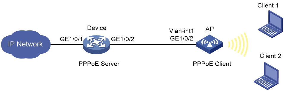
Network configuration
As shown in Figure 1, the wireless clients access the network through the AP. The AP assigns IP addresses to the clients as a DHCP server. The device acts as a PPPoE server, and the AP acts as a PPPoE client.
Configure the device and the AP to meet the following requirements:
· The device performs one-way authentication on the wireless clients without using usernames.
· The PPPoE session on the AP works in permanent mode.
· Clients can initiate connection requests to access the resources in the IP network.
Procedures
Configuring the device
# Create a network access user named user1.
<Device> system-view
[Device] local-user user1 class network
# Set the password to pass1 in plaintext form for the user, and authorize the user to use the PPP service.
[Device-luser-network-user1] password simple pass1
[Device-luser-network-user1] service-type ppp
[Device-luser-network-user1] quit
# Create VT interface 1.
[Device] interface virtual-template 1
# Configure the VT interface to authenticate the peer by using CHAP, with the authentication domain as domain system.
[Device-Virtual-Template1] ppp authentication-mode chap domain system
# Configure an IP address for the VT interface and specify an IP address for the peer.
[Device-Virtual-Template1] ip address 1.1.1.1 255.255.255.0
[Device-Virtual-Template1] remote address 1.1.1.2
[Device-Virtual-Template1] quit
# Enable the PPPoE server on GigabitEthernet 1/0/2, and bind the interface to the VT interface.
[Device] interface gigabitethernet 1/0/2
[Device-GigabitEthernet1/0/2] pppoe-server bind virtual-template 1
[Device-GigabitEthernet1/0/2] quit
# Configure local authentication for the PPP users in ISP domain system.
[Device] domain system
[Device-isp-system] authentication ppp local
[Device-isp-system] quit
Configuring the AP
1. Configure VLANs and VLAN interfaces on the AP:
# Create VLAN 100 and its VLAN interface, and assign an IP address to the VLAN interface.
<AP> system-view
[AP] vlan 100
[AP-vlan100] quit
[AP] interface vlan-interface 100
[AP-Vlan-interface100] ip address 192.1.0.1 24
[AP-Vlan-interface100] quit
2. Configure the wireless service template:
# Create a service template named service and enter its view.
[AP] wlan service-template service
# Configure service as the SSID.
[AP-wlan-st-service] ssid service
# Assign clients coming online through service template 100 to VLAN 100.
[AP-wlan-st-service] vlan 100
# Configure the PSK AKM mode and the 12345678 plaintext key.
[AP-wlan-st-service] akm mode psk
[AP-wlan-st-service] preshared-key pass-phrase simple 12345678
# Configure CCMP as the cipher suite and RSN as the security IE.
[AP-wlan-st-service] cipher-suite ccmp
[AP-wlan-st-service] security-ie rsn
# Enable the service template.
[AP-wlan-st-service] service-template enable
[AP-wlan-st-service] quit
# Enter interface view of WLAN-Radio 1/0/1.
[AP] interface wlan-radio 1/0/1
# Bind service template service to interface WLAN-Radio 1/0/1.
[AP-WLAN-Radio1/0/1] service-template service
[AP-WLAN-Radio1/0/1] quit
3. Configure the DHCP server:
# Configure DHCP address pool 100 for address allocation to the wireless clients.
[AP] dhcp server ip-pool 100
[AP-dhcp-pool-100] network 192.1.0.0 mask 255.255.255.0
[AP-dhcp-pool-100] gateway-list 192.1.0.1
[AP-dhcp-pool-100] quit
# Enable the DHCP service.
[AP] dhcp enable
4. Configure the PPPoE client:
# Create dialer group 1 and configure a dial rule for it.
[AP] dialer-group 1 rule ip permit
# Enable bundle DDR on Dialer 1.
[AP] interface dialer 1
[AP-Dialer1] dialer bundle enable
# Associate Dialer 1 with dialer group 1.
[AP-Dialer1] dialer-group 1
# Configure Dialer 1 to obtain an IP address through PPP negotiation.
[AP-Dialer1] ip address ppp-negotiate
[AP-Dialer1] quit
# Configure a PPPoE session that corresponds to dialer bundle 1 (dialer bundle 1 corresponds to Dialer 1).
[AP] interface vlan-interface 1
[AP-Vlan-interface1] pppoe-client dial-bundle-number 1
[AP-Vlan-interface1] quit
# Configure the PPPoE session to operate in permanent mode.
[AP] interface dialer 1
[AP-Dialer1] dialer timer idle 0
# Set the DDR auto-dial interval to 60 seconds.
[AP-Dialer1] dialer timer autodial 60
# Configure the username and password for CHAP authentication.
[AP-Dialer1] ppp chap user user1
[AP-Dialer1] ppp chap password simple pass1
[AP-Dialer1] quit
# Configure a static route.
[AP] ip route-static 1.1.1.1 255.0.0.0 dialer 1
5. Configure NAT:
# Configure ACL 2000 to permit packets sourced from 192.1.0.0.
[AP] acl basic 2000
[AP-acl-ipv4-basic-2000] rule 0 permit source 192.1.0.0 0.0.0.255
[AP-acl-ipv4-basic-2000] quit
# Configure an outbound dynamic PAT rule on VLAN-interface 1 to translate the source IP addresses permitted by ACL 2000.
[AP] interface vlan-interface 1
[AP-Vlan-interface1] nat outbound 2000
[AP-Vlan-interface1] quit
Verifying the configuration
# Display summary information about the PPPoE session on the AP.
[AP] display pppoe-client session summary
Bundle ID Interface VA RemoteMAC LocalMAC State
1 1 Vlan1 VA0 00e0-1400-4300 00e0-1500-4100 SESSION
Configuration files
#
sysname Device
#
vlan 1
#
interface Virtual-Template1
ppp authentication-mode chap domain system
remote address 1.1.1.2
ip address 1.1.1.1 255.255.255.0
#
interface GigabitEthernet 1/0/2
port link-mode route
pppoe-server bind virtual-template 1
#
domain system
authentication ppp local
#
domain default enable system
#
local-user user1 class network
password cipher $c$3$d3q9pKjQeMNyFxOjfKRkD7HF6XDPDFet
service-type ppp
authorization-attribute user-role network-operator
#
Return
· AP:
#
sysname AP
#
dialer-group 1 rule ip permit
#
dhcp enable
#
vlan 1
#
vlan 100
#
dhcp server ip-pool 100
gateway-list 192.1.0.1
network 192.1.0.0 mask 255.255.255.0
#
wlan service-template service
ssid service
vlan 100
akm mode psk
preshared-key pass-phrase cipher $c$3$7hZ2DNiI+h/ajPE7DhZbD6Y7py9vqf4721sp
cipher-suite ccmp
security-ie rsn
service-template enable
#
interface Dialer1
ppp chap password cipher $c$3$y9xXZso6tDA2+FSK8p+0qiC61/eATRxj
ppp chap user user1
dialer bundle enable
dialer-group 1
dialer timer idle 0
dialer timer autodial 60
ip address ppp-negotiate
nat outbound 2000
#
interface Vlan-interface1
pppoe-client dial-bundle-number 1
#
interface Vlan-interface100
ip address 192.1.0.1 255.255.255.0
#
interface WLAN-Radio1/0/1
service-template service
#
ip route-static 1.1.1.0 24 Dialer1
#
acl basic 2000
rule 0 permit source 192.1.0.0 0.0.0.255
#
return
Related documentation
· Network Connectivity Command Reference in H3C Access Points Command References
· Network Connectivity Configuration Guide in H3C Access Points Configuration Guides
· WLAN Access Command Reference in H3C Access Points Command References
· WLAN Access Configuration Guide in H3C Access Points Configuration Guides