- Table of Contents
- Related Documents
-
| Title | Size | Download |
|---|---|---|
| 01-Text | 1.12 MB |
Table of Contents
Installing PFC to the Specified Position
Installing PFC into a Standard 19-Inch Rack
Placing the PFC on a Workbench
Introduction to Interface Cards
Connecting the Cables of the 8EPM
Connecting the Optical Fibers of the 4FPM
Product Overview
Overview
The H3C SecPath Power Free Connector (PFC) is developed by New H3C Technologies Co., Ltd. (hereinafter referred to as H3C) to provide power-failure protection for Intrusion Prevention System (IPS) and Firewall (FW). Hereinafter, the H3C SecPath PFC is called PFC, and the IPS and FW are both called device for short.
During device operation, uncontrollable causes can affect the network stability. To solve the problem, you can deploy a PFC in the network, then:
· If a power failure, reboot, or interface down occurs, the PFC takes over the traffic to be processed by the device immediately and directly forwards the traffic to the next hop.
· After the device is powered on and rebooted, or the interface becomes up, the PFC switches traffic to the device.
Because the PFC switchover interval is very short, the network stability is ensured effectively.
How PFC Works
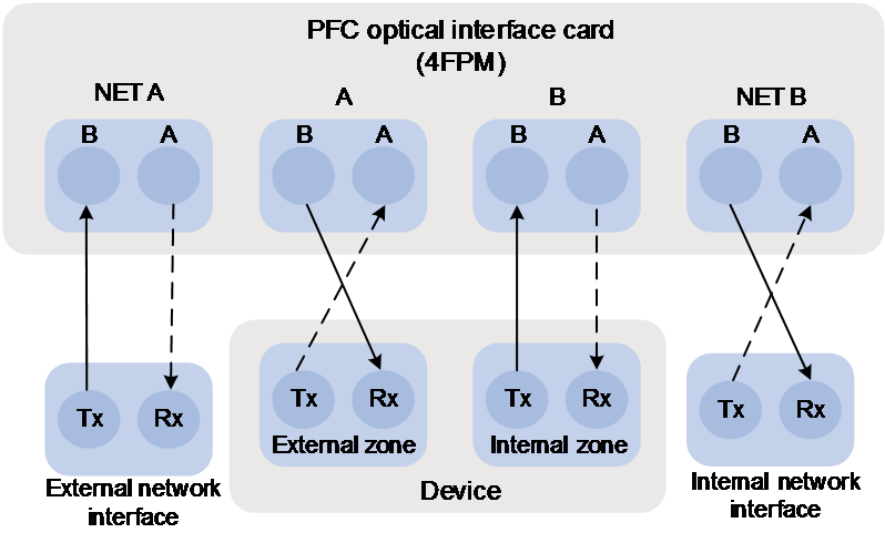
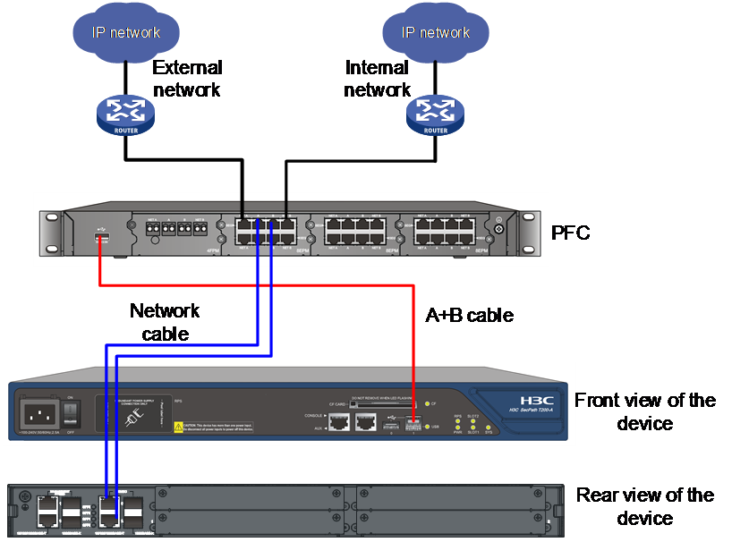
Figure 1 Work mechanism of PFC
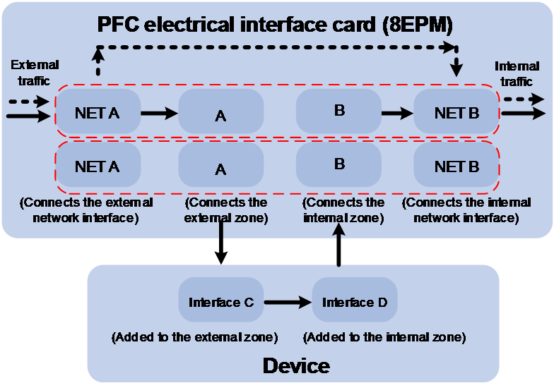
As shown in Figure 1, the PFC interface card (take an 8EPM electrical interface card for example) has eight interfaces, which are NET A, A, B, and NET B in each of the two rows. Each row of interfaces protects a segment.
· NET A connects to the external network interface.
· A connects to the interface added to the external zone of the device.
· B connects to the interface added to the internal zone of the device.
· NET B connects to the internal network interface.
The traffic direction differs with circumstances:
1. The solid line in Figure 1 shows the traffic direction when the device is operating correctly. The external traffic enters the device through NET A, and passes through interface A, the internal zone and external zone of the device. Then it enters PFC through interface B and then flows to NET B. Finally, it reaches the internal network.
2. If a power failure, reboot, or interface down occurs on the device, NET A and NET B are connected directly, and traffic will pass through NET A to NET B directly without passing through A, B, C and D. The dashed line in Figure 1 indicates the traffic direction.
Note that:
· To make sure the PFC can work normally when the device is working abnormally, enable external security service bypass on the device. For details, see the Layer 2—LAN Switching configuration guide for the PFC.
· Interfaces NET A and A have peering relationship with interfaces NET B and B, that is, they can be deployed in the reverse sequence. For more information, see Table 1.
Table 1 Traffic direction in the PFC
|
Device status |
Traffic direction |
|
The device is operating correctly |
External network interface > NET A > A > interface added to the external zone of the device > interface added to the internal zone of the device > B > NET B > internal network interface (follows the direction indicated by the solid line) or External network interface > NET B > B > interface added to the external zone of the device > interface added to the internal zone of the device > A > NET A > internal network interface (in the reverse direction as indicated by the solid line). |
|
A power failure, reboot, or interface down occurs |
External network interface > NET A > NET B > internal network interface (follows the direction indicated by the dashed line) or External network interface > NET B > NET A > internal network interface (in the reverse direction as indicated by the dashed line) |
· If the device is configured with two segments and is connected to the PFC, the interface down event of one segment will trigger the PFC to perform a traffic switchover. Power failure and link state changes can cause a working mode change of the PFC.
Hardware Specifications
Table 2 PFC hardware specifications
|
Item |
Description |
|
Physical dimensions (H × W × D) |
43.6 × 440 × 260 mm (1.72 × 17.32 × 10.24 in) |
|
Weight |
5 kg (11.02 lb) |
|
Voltage |
5 VDC (inputted through the USB interface) |
|
Operating environment |
Operating temperature: 0°C to 40°C (32°F to 104°F) Storage temperature: –20°C to +70°C (–4°F to +158°F) Operating humidity: 10% to 85% (noncondensing) Storage humidity: 5% to 90% (noncondensing) |
|
USB interface (type A connector) |
When PFC starts to work, it needs to be connected to the device through a USB cable to obtain power supply. |
Appearance
Front Panel
Figure 2 Front panel of PFC
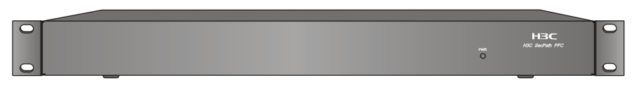
The front panel of PFC has a power LED (PWR), which indicates the current working state of the PFC. Table 3 gives the LED description.
|
Status |
Description |
|
On |
The PFC is operating correctly. |
|
Blinking |
The PFC is not operating or operating incorrectly. |
|
Off |
The PFC is not operating or operating incorrectly. |
Rear Panel
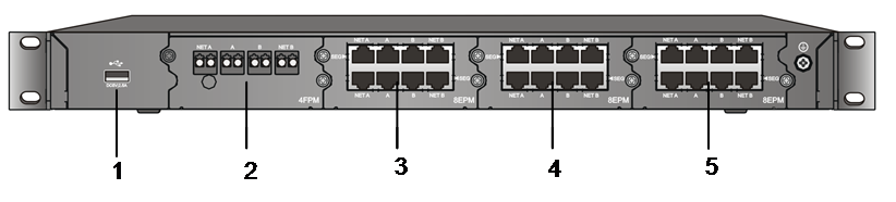
As shown in Figure 3, the real panel of PFC has one USB interface and four slots. PFC obtains power supply by connecting to the device through a USB cable at initial startup. The four slots, which are used for interface expansion, support 4FPM and 8EPM interface cards. You can select any type of interface card as needed. For more information about the 4FPM and 8EPM interface cards, see "Introduction to Interface Cards."
Figure 3 Rear panel of the PFC
|
(1) USB interface |
(2) to (5) four slots |
In Figure 3, one 4FPM and three 8EPM interface cards are installed in PFC.
Installing PFC
Safety Precautions
|
|
WARNING! Installation and removal of the unit and its accessories must be carried out by qualified personnel. You must read all of the Safety Instructions supplied with your device before installation and operation. |
Installation Guidelines
|
|
NOTE: Do not remove the dismantlement-preventive seal on PFC without permission. If you want to dismantle it, you should contact the local agent of H3C for permission. Otherwise, H3C shall not be held liable for any consequence caused thereby. |
To avoid any device impairment and bodily injury caused by improper use, observe these rules:
· Wear an ESD wrist strap (not provided with the device) and ensure a good skin contact.
· Keep the PFC away from high-power radio transmitters, radars, and high-frequency heavy-current devices. Use electromagnetic shielding when necessary.
· Ensure good ventilation and heat dissipation for the PFC.
· Place no objects on the PFC to avoid damage to the PFC or impact to dissipation efficiency.
· To stack PFCs, keep a vertical distance of 1.5 cm (0.59 in) between devices for the sake of ventilation and heat dissipation.
Installing PFC to the Specified Position
After preparation, start installing the PFC.
Depending on the installation sites, PFC can be installed:
· In a standard 19-inch rack
Installing PFC into a Standard 19-Inch Rack
You can install PFC in a standard 19-inch rack. According to the installation position of the mounting brackets, you have the following two installation options:
· Installing the mounting brackets to the front part of PFC
· Installing the mounting brackets to the middle part of PFC
Introduction to mounting brackets
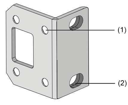
The mounting bracket provided with the PFC is as shown in Figure 4.
Figure 4 Appearance of the mounting bracket
|
(1) Screw hole for fixing the mounting bracket to PFC |
|
(2) Screw hole (for M6 screw) for fixing the mounting bracket to the rack |
Installing the PFC
The procedures for installing the mounting brackets to the font part and middle part of the PFC are similar. Follow these steps to install the mounting brackets to the front part of the PFC.
2. Use the screws to fix the left and right mounting brackets to the two sides of the front panel, as shown in Figure 5.
Figure 5 Install the mounting brackets to the chassis
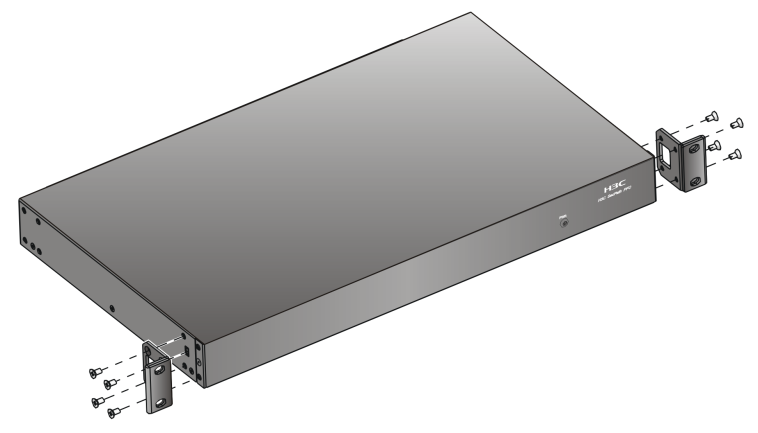
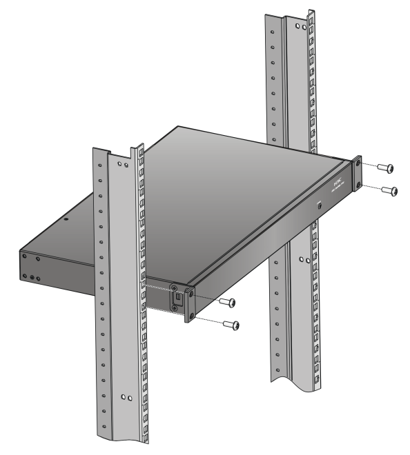
Figure 6 Install the PFC to the rack
Placing the PFC on a Workbench
Without a standard 19-inch rack, you can place the PFC on a clean workbench. Make sure that:
· The workbench is long and wide enough to hold the PFC. See Table 2 for the physical dimensions of PFC.
· The workbench is sturdy and well grounded.
· The workbench is firm enough to support the weight of the PFC and other installation accessories.
· There is a clearance of 10 cm (3.94 in.) around the chassis for heat dissipation.
Installing the Interface Card
Introduction to Interface Cards
PFC supports the following two types of interface cards:
· Optical interface card (4FPM)
· Electrical interface card (8EPM)
Figure 7 and Figure 8 show the appearance of the two interface cards.
Figure 7 Appearance of the 4FPM interface card
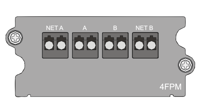
Figure 8 Appearance of the 8EPM interface card
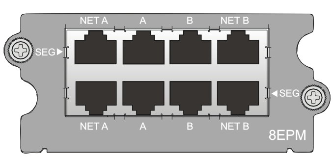
Table 4 shows the specifications of the 4FPM and 8EPM.
Table 4 Specifications of the 4FPM and 8EPM
|
Item |
4FPM |
8EPM |
|
Interface type |
LC |
RJ-45 |
|
Interface number |
4 |
8 |
|
Segment number |
1 |
2 |
|
Hot swapping |
Supported |
Supported |
|
Cable requirements |
850nm/1310nm multimode optical fiber |
Category 5 or higher shielded twisted pair (STP) |
Installing the Interface Card
No interface card is shipped with PFC by default. You can select interface cards as needed.
Before installation, prepare tools such as Phillips screwdriver and ESD wrist strap.
Follow these steps to install an interface card:
1. Wear the ESD wrist strap correctly.
2. Use the Phillips screwdriver to remove the filler panel from the slot to be used (the first slot is not installed with a filler panel by default).
3. Gently push the interface card horizontally along the guide rails until it touches the backplane of the PFC.
4. Fix the captive screws on the interface card.
Connecting Cables
|
|
CAUTION: Do not connect the PFC to an operating device. Otherwise, the device may work abnormally. |
Connecting the Cables of the 8EPM
The PFC does not provide interface cables. You need to prepare them (network cables) by yourself.
The connections between the PFC and interfaces of the device are as shown in How PFC Works. One connection method is: Interfaces NET A and NET B are connected to the external and internal network interfaces of the user network, respectively; interfaces A and B are connected to the interfaces added to the external and internal zones, respectively. The other connection method is: Interfaces NET A and NET B are connected to the internal and external network interfaces of the user network, respectively; interfaces A and B are connected to the interfaces added to the internal and external zones, respectively.
Connecting the Optical Fibers of the 4FPM
The connection method is as shown in Figure 9.
Figure 9 Connect the optical fibers of the 4FPM
Both single-mode and multimode optical interfaces can be connected to the optical interfaces of 4FPM, but the wavelength provided by the peer interface card must be 850 nm or 1310 nm. Additionally, the attributes of the optical interfaces on the device must be consistent with those on the peer device. Otherwise, the link connectivity may be unavailable. In this sense, the PFC is transparent to the device and the peer device.
The attributes of optical interfaces include the following:
· Optical transmit power
· Receive sensitivity
· Overload optical power
· Central wavelength
· Maximum transmission distance
· Fiber type
|
|
CAUTION: · Never stare into an open optical interface, because invisible rays may be emitted from the optical interface. · Install the protective cover to the optical interface that is not connected to any optical fiber connector to prevent dust from entering the optical interface. · Avoid excessively bending the optical fiber cables, with the curvature radium less than 10 cm (3.94 in.). |
Connecting the USB Cable
|
|
CAUTION: To ensure correct operation of the PFC, use the USB cable provided with the device. |
PFC needs to be connected to the device through a USB cable to obtain power supply. The following figures are for illustration only.
Two types of USB cables are provided with PFC:
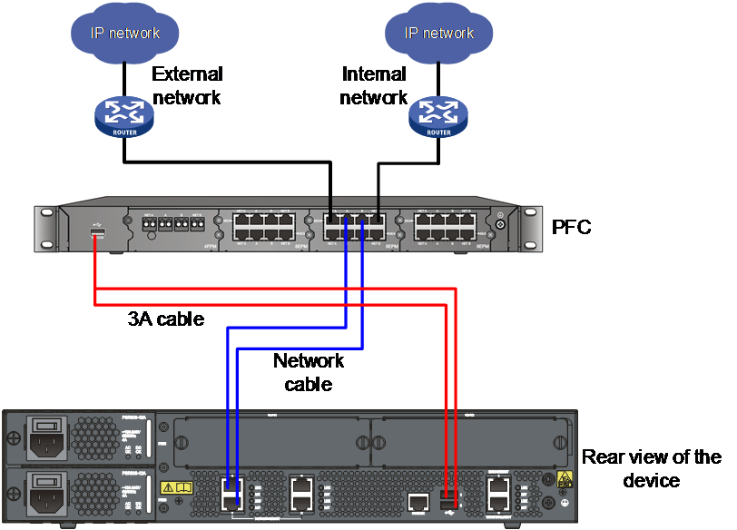
· The first type of USB cable has three connectors on two ends, a single-connector end and a dual-connector end. All the three connectors are type A connectors. This type of USB cable is called 3A cable hereinafter. 3A cables apply to devices with two type A USB interfaces, as shown in Figure 10. If an electrical interface card is installed on the PFC, connect the single-connector end to the USB interface on PFC, and the dual-connector end to the two type A USB interfaces on the device, as shown in Figure 11. If an optical interface card is installed on the PFC, connect the single-connector end to the USB interface on PFC, and one of the connectors on the dual-connector end to one type A USB interface on the device.
Figure 10 Single-connector end of the 3A cable and the corresponding type A USB interface
Figure 11 Connect the 3A USB cable
· The other type of USB cable has two ends, a type A connector at one end and a type B connector at the other end. This type of USB cable is called A+B cable hereinafter. A+B cables apply to devices with type B USB interfaces, as shown in Figure 12. When using the A+B cable, connect the type A connector to the USB interface on PFC and the type B connector to the USB interface on the device, as shown in Figure 13.
Figure 12 B connector of the A+B cable and the corresponding type B USB interface
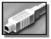
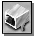
Figure 13 Connect the A+B USB cable
After connecting the interface and USB cables, follow the steps described in Debugging the PFC to debug PFC. If no problem arises, the PFC can work normally.
Debugging the PFC
Debugging must be carried out after all cables are connected. Follow these steps to perform debugging:
1. Use two network cables to connect the external network interface to NET A and internal network interface to NET B, respectively. Do not connect the PFC to any device (including the network interface and USB interface). Then, check the link.
|
|
CAUTION: The sequence for connecting network cables must comply with the requirement of the user network; otherwise, the link connectivity may be unavailable. For example, if you used a crossover cable to connect the external and internal network interfaces before connecting the PFC, you need to use a crossover cable to connect the external network interface and NET A and a straight-through cable to connect NET B and the internal network interface after connecting the PFC. |
2. If the link is normal, use two network cables to connect interface A to the interface added to the external zone and interface B to the interface added to the internal zone. Then, restart the device. After the device is restarted, check the link. The traffic direction should be: external network interface > NET A > A > interface added to the external zone > interface added to the internal zone > B > NET B > internal network interface.
If the link is normal in both step 1 and 2, the hardware installation and cable connection of PFC are correct.
Configuration Guidelines
1. Do not unplug the USB cable while the device is operating. Otherwise, the device may reboot.
2. If an error occurs while the device is rebooting, the network operation is not affected because the device has not completed the whole reboot process and thus does not ask the PFC to perform traffic switchover.
3. If an error occurs and the control plane fails when the device is operating, the device cannot control the USB interface, and the PFC cannot perform traffic switchover.
