- Table of Contents
-
- 06-Layer 3—IP Services Configuration Guide
- 00-Preface
- 01-ARP configuration
- 02-IP addressing configuration
- 03-DHCP configuration
- 04-DNS configuration
- 05-NAT configuration
- 06-AFT configuration
- 07-IP forwarding basics configuration
- 08-Fast forwarding configuration
- 09-Multi-CPU packet distribution configuration
- 10-Adjacency table configuration
- 11-IP performance optimization configuration
- 12-IPv6 basics configuration
- 13-IPv6 fast forwarding configuration
- 14-Tunneling configuration
- 15-GRE configuration
- 16-WAAS configuration
- Related Documents
-
| Title | Size | Download |
|---|---|---|
| 03-DHCP configuration | 171.35 KB |
Restrictions: Hardware compatibility with DHCP
Vendor-specific option (Option 43)
Relay agent option (Option 82)
Restrictions and guidelines: DHCP client configuration
Enabling the DHCP client on an interface
Configuring a DHCP client ID for an interface
Enabling duplicated address detection
Setting the DSCP value for DHCP packets sent by the DHCP client
Display and maintenance commands for DHCP client
DHCP client configuration examples
Example: Configuring DHCP client
Obtaining an IP address dynamically
Configuring an interface to use BOOTP for IP address acquisition
Display and maintenance commands for BOOTP client
BOOTP client configuration examples
Example: Configuring BOOTP client
DHCP overview
Restrictions: Hardware compatibility with DHCP
|
Series |
Models |
DHCP compatibility |
|
L5000 series |
L5000-C, L5000-S |
Yes |
|
L5000-E, L5030, L5060, L5080, L5000-AK535 |
No |
|
|
L1000 series |
L1000-C, L1000-S, L1000-M, L1000-E, L1000-AK310, L1000-AK315, L1000-AK320, L1000-AK325, L1000-AK330, L1000-AK390, L1030, L1050, L1070, L1090 |
Yes |
|
L100 series |
L100-C |
Yes |
|
Modules |
LSU1ADECEA0, LSWM1ADED0, LSQM1ADEDSC0 |
Yes |
DHCP network model
The Dynamic Host Configuration Protocol (DHCP) provides a framework to assign configuration information to network devices.
Figure 1 shows a typical DHCP application scenario where the DHCP clients and the DHCP server reside on the same subnet. The DHCP clients can also obtain configuration parameters from a DHCP server on another subnet through a DHCP relay agent.
Figure 1 A typical DHCP application

DHCP address allocation
Allocation mechanisms
DHCP supports the following allocation mechanisms:
· Static allocation—The network administrator assigns an IP address to a client, such as a WWW server, and DHCP conveys the assigned address to the client.
· Automatic allocation—DHCP assigns a permanent IP address to a client.
· Dynamic allocation—DHCP assigns an IP address to a client for a limited period of time, which is called a lease. Most DHCP clients obtain their addresses in this way.
IP address allocation process
Figure 2 IP address allocation process

As shown in Figure 2, a DHCP server assigns an IP address to a DHCP client in the following process:
1. The client broadcasts a DHCP-DISCOVER message to locate a DHCP server.
2. Each DHCP server offers configuration parameters such as an IP address to the client in a DHCP-OFFER message. The sending mode of the DHCP-OFFER is determined by the flag field in the DHCP-DISCOVER message. For more information, see "DHCP message format."
3. If the client receives multiple offers, it accepts the first received offer, and broadcasts it in a DHCP-REQUEST message to formally request the IP address. (IP addresses offered by other DHCP servers can be assigned to other clients.)
4. All DHCP servers receive the DHCP-REQUEST message. However, only the server selected by the client does one of the following operations:
¡ Returns a DHCP-ACK message to confirm that the IP address has been allocated to the client.
¡ Returns a DHCP-NAK message to deny the IP address allocation.
After receiving the DHCP-ACK message, the client verifies the following details before using the assigned IP address:
· The assigned IP address is not in use. To verify this, the client broadcasts a gratuitous ARP packet. The assigned IP address is not in use if no response is received within the specified time.
· The assigned IP address is not on the same subnet as any IP address in use on the client.
Otherwise, the client sends a DHCP-DECLINE message to the server to request an IP address again.
IP address lease extension
A dynamically assigned IP address has a lease. When the lease expires, the IP address is reclaimed by the DHCP server. To continue using the IP address, the client must extend the lease duration.
When about half of the lease duration elapses, the DHCP client unicasts a DHCP-REQUEST to the DHCP server to extend the lease. Depending on the availability of the IP address, the DHCP server returns one of the following messages:
· A DHCP-ACK unicast confirming that the client's lease duration has been extended.
· A DHCP-NAK unicast denying the request.
If the client receives no reply, it broadcasts another DHCP-REQUEST message for lease extension when about seven-eighths of the lease duration elapses. Again, depending on the availability of the IP address, the DHCP server returns either a DHCP-ACK unicast or a DHCP-NAK unicast.
DHCP message format
Figure 3 shows the DHCP message format. DHCP uses some of the fields in significantly different ways. The numbers in parentheses indicate the size of each field in bytes.
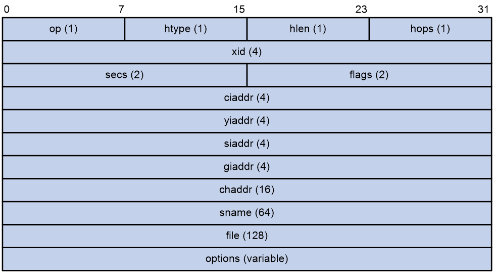
· op—Message type defined in options field. 1 = REQUEST, 2 = REPLY
· htype, hlen—Hardware address type and length of the DHCP client.
· hops—Number of relay agents a request message traveled.
· xid—Transaction ID, a random number chosen by the client to identify an IP address allocation.
· secs—Filled in by the client, the number of seconds elapsed since the client began address acquisition or renewal process. This field is reserved and set to 0.
· flags—The leftmost bit is defined as the BROADCAST (B) flag. If this flag is set to 0, the DHCP server sent a reply back by unicast. If this flag is set to 1, the DHCP server sent a reply back by broadcast. The remaining bits of the flags field are reserved for future use.
· ciaddr—Client IP address if the client has an IP address that is valid and usable. Otherwise, set to zero. (The client does not use this field to request an IP address to lease.)
· yiaddr—Your IP address. It is an IP address assigned by the DHCP server to the DHCP client.
· siaddr—Server IP address, from which the client obtained configuration parameters.
· giaddr—Gateway IP address. It is the IP address of the first relay agent to which a request message travels.
· chaddr—Client hardware address.
· sname—Server host name, from which the client obtained configuration parameters.
· file—Boot file (also called system software image) name and path information, defined by the server to the client.
· options—Optional parameters field that is variable in length. Optional parameters include the message type, lease duration, subnet mask, domain name server IP address, and WINS IP address.
DHCP options
DHCP extends the message format as an extension to BOOTP for compatibility. DHCP uses the options field to carry information for dynamic address allocation and provide additional configuration information for clients.
Figure 4 DHCP option format

Common DHCP options
The following are common DHCP options:
· Option 3—Router option. It specifies the gateway address to be assigned to the clients.
· Option 6—DNS server option. It specifies the DNS server IP address to be assigned to the clients.
· Option 33—Static route option. It specifies a list of classful static routes (the destination addresses in these static routes are classful) that a client should add into its routing table. If both Option 33 and Option 121 exist, Option 33 is ignored.
· Option 51—IP address lease option.
· Option 53—DHCP message type option. It identifies the type of the DHCP message.
· Option 55—Parameter request list option. It is used by a DHCP client to request specified configuration parameters. The option includes values that correspond to the parameters requested by the client.
· Option 60—Vendor class identifier option. A DHCP client uses this option to identify its vendor. A DHCP server uses this option to distinguish DHCP clients, and assigns IP addresses to them.
· Option 66—TFTP server name option. It specifies the TFTP server domain name to be assigned to the clients.
· Option 67—Boot file name option. It specifies the boot file name to be assigned to the client.
· Option 121—Classless route option. It specifies a list of classless static routes (the destination addresses in these static routes are classless) that a client should add into its routing table. If both Option 33 and Option 121 exist, Option 33 is ignored.
· Option 150—TFTP server IP address option. It specifies the TFTP server IP address to be assigned to the clients.
For more information about DHCP options, see RFC 2132 and RFC 3442.
Custom DHCP options
Some options, such as Option 43, Option 82, and Option 184, have no standard definitions in RFC 2132.
Vendor-specific option (Option 43)
Option 43 function
DHCP servers and clients use Option 43 to exchange vendor-specific configuration information.
The DHCP client can obtain the following information through Option 43:
· ACS parameters, including the ACS URL, username, and password.
· Service provider identifier, which is acquired by the CPE from the DHCP server and sent to the ACS for selecting vender-specific configurations and parameters.
· PXE server address, which is used to obtain the boot file or other control information from the PXE server.
· AC address, which is used by an AP to obtain the boot file or other control information from the AC.
Option 43 format
Figure 5 Option 43 format
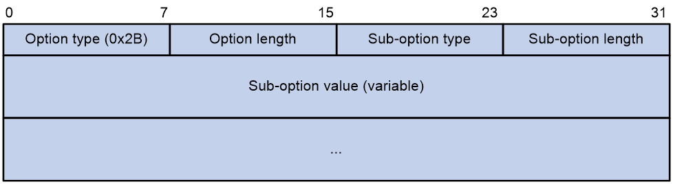
Network configuration parameters are carried in different sub-options of Option 43 as shown in Figure 5.
· Sub-option type—The field value can be 0x01 (ACS parameter sub-option), 0x02 (service provider identifier sub-option), or 0x80 (PXE server address sub-option).
· Sub-option length—Excludes the sub-option type and sub-option length fields.
· Sub-option value—The value format varies by sub-option.
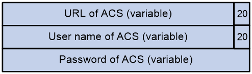
Sub-option value field format
· ACS parameter sub-option value field—Includes the ACS URL, username, and password separated by spaces (hexadecimal number 20) as shown in Figure 6.
Figure 6 ACS parameter sub-option value field
· Service provider identifier sub-option value field—Includes the service provider identifier.
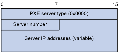
· PXE server address sub-option value field—Includes the PXE server type that can only be 0, the server number that indicates the number of PXE servers contained in the sub-option, and server IP addresses, as shown in Figure 7.
Figure 7 PXE server address sub-option value field
Relay agent option (Option 82)
Option 82 is the relay agent option. It records the location information about the DHCP client. When a DHCP relay agent or DHCP snooping device receives a client's request, it adds Option 82 to the request and sends it to the server.
The administrator can use Option 82 to locate the DHCP client and further implement security control and accounting. The DHCP server can use Option 82 to provide individual configuration policies for the clients.
Option 82 can include a maximum of 255 sub-options and must include a minimum of one sub-option. Option 82 supports the following sub-options: sub-option 1 (Circuit ID), and sub-option 2 (Remote ID). Option 82 has no standard definition. Its padding formats vary by vendor.
· Circuit ID has the following padding modes:
¡ String padding mode—Includes a character string specified by the user.
¡ Normal padding mode—Includes the VLAN ID and interface number of the interface that receives the client's request.
¡ Verbose padding mode—Includes the access node identifier specified by the user, and the VLAN ID, interface number and interface type of the interface that receives the client's request.
· Remote ID has the following padding modes:
¡ String padding mode—Includes a character string specified by the user.
¡ Normal padding mode—Includes the MAC address of the DHCP relay agent interface or the MAC address of the DHCP snooping device that receives the client's request.
¡ Sysname padding mode—Includes the name of the device. To set the device name, use the sysname command in system view.
Option 184
Option 184 is a reserved option. You can define the parameters in the option as needed. The device supports Option 184 carrying voice related parameters, so a DHCP client with voice functions can get voice parameters from the DHCP server.
Option 184 has the following sub-options:
· Sub-option 1—Specifies the IP address of the primary network calling processor. The primary processor acts as the network calling control source and provides program download services. For Option 184, you must define sub-option 1 to make other sub-options take effect.
· Sub-option 2—Specifies the IP address of the backup network calling processor. DHCP clients contact the backup processor when the primary one is unreachable.
· Sub-option 3—Specifies the voice VLAN ID and the result whether the DHCP client takes this VLAN as the voice VLAN.
· Sub-option 4—Specifies the failover route that includes the IP address and the number of the target user. A SIP VoIP user uses this IP address and number to directly establish a connection to the target SIP user when both the primary and backup calling processors are unreachable.
Protocols and standards
· RFC 2131, Dynamic Host Configuration Protocol
· RFC 2132, DHCP Options and BOOTP Vendor Extensions
· RFC 1542, Clarifications and Extensions for the Bootstrap Protocol
· RFC 3046, DHCP Relay Agent Information Option
· RFC 3442, The Classless Static Route Option for Dynamic Host Configuration Protocol (DHCP) version 4
Configuring the DHCP client
About DHCP client
With DHCP client enabled, an interface uses DHCP to obtain configuration parameters from the DHCP server, for example, an IP address.
Restrictions and guidelines: DHCP client configuration
The DHCP client configuration is supported only on Layer 3 Ethernet interfaces (or subinterfaces), VLAN interfaces, and Layer 3 aggregate interfaces.
DHCP client tasks at a glance
To configure a DHCP client, perform the following tasks:
1. Enabling the DHCP client on an interface
2. Configuring a DHCP client ID for an interface
3. (Optional.) Enabling duplicated address detection
4. (Optional.) Setting the DSCP value for DHCP packets sent by the DHCP client
Enabling the DHCP client on an interface
Restrictions and guidelines
· If the number of IP address request failures reaches the system-defined amount, the DHCP client-enabled interface uses a default IP address.
· An interface can be configured to acquire an IP address in multiple ways. The new configuration overwrites the old.
· Secondary IP addresses cannot be configured on an interface that is enabled with the DHCP client.
· If the interface obtains an IP address on the same segment as another interface on the device, the interface does not use the assigned address. Instead, it requests a new IP address from the DHCP server.
Procedure
1. Enter system view.
system-view
2. Enter interface view.
interface interface-type interface-number
3. Configure an interface to use DHCP for IP address acquisition.
ip address dhcp-alloc
By default, an interface does not use DHCP for IP address acquisition.
Configuring a DHCP client ID for an interface
About this task
A DHCP client ID is added to the DHCP option 61 to uniquely identify a DHCP client. A DHCP server can assign IP addresses to clients based on their DHCP client IDs.
DHCP client ID includes an ID type and a type value. Each ID type has a fixed type value. You can specify a DHCP client ID by using one of the following methods:
· Use an ASCII string as the client ID. If an ASCII string is used, the type value is 00.
· Use a hexadecimal number as the client ID. If a hexadecimal number is used, the type value is the first two characters in the number.
· Use the MAC address of an interface to generate a client ID. If this method is used, the type value is 01.
The type value of a DHCP client ID can be displayed by the display dhcp server ip-in-use or display dhcp client command.
Restrictions and guidelines
Make sure the ID for each DHCP client is unique.
Procedure
1. Enter system view.
system-view
2. Enter interface view.
interface interface-type interface-number
3. Configure a DHCP client ID for the interface.
dhcp client identifier { ascii ascii-string | hex hex-string | mac interface-type interface-number }
By default, an interface generates the DHCP client ID based on its MAC address. If the interface has no MAC address, it uses the MAC address of the first Ethernet interface to generate its client ID.
Enabling duplicated address detection
About this task
DHCP client detects IP address conflict through ARP packets. An attacker can act as the IP address owner to send an ARP reply. The spoofing attack makes the client unable to use the IP address assigned by the server. As a best practice, disable duplicate address detection when ARP attacks exist on the network.
Procedure
1. Enter system view.
system-view
2. Enable duplicate address detection.
dhcp client dad enable
By default, the duplicate address detection feature is enabled on an interface.
Setting the DSCP value for DHCP packets sent by the DHCP client
About this task
The DSCP value of a packet specifies the priority level of the packet and affects the transmission priority of the packet.
Procedure
1. Enter system view.
system-view
2. Set the DSCP value for DHCP packets sent by the DHCP client.
dhcp client dscp dscp-value
By default, the DSCP value in DHCP packets sent by the DHCP client is 56.
Display and maintenance commands for DHCP client
Execute display command in any view.
|
Task |
Command |
|
Display DHCP client information. |
display dhcp client [ verbose ] [ interface interface-type interface-number ] |
DHCP client configuration examples
Example: Configuring DHCP client
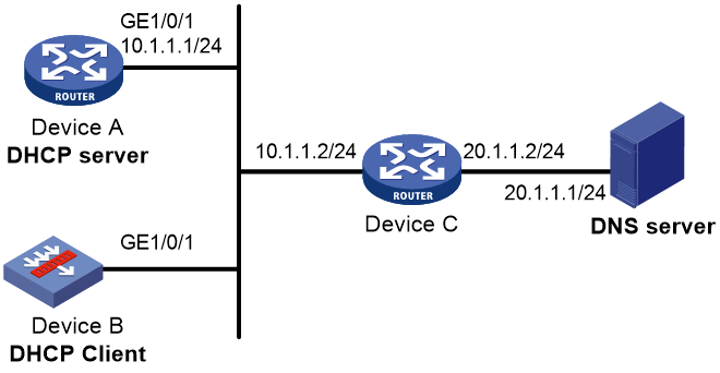
Network configuration
As shown in Figure 9, Device B contacts the DHCP server through GigabitEthernet 1/0/1 to obtain an IP address, a DNS server address, and static route information. The DHCP client's IP address resides on subnet 10.1.1.0/24. The DNS server address is 20.1.1.1. The next hop of the static route to subnet 20.1.1.0/24 is 10.1.1.2.
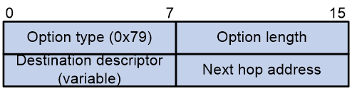
The DHCP server uses Option 121 to assign static route information to DHCP clients. Figure 8 shows the Option 121 format. The destination descriptor field contains the following parts: subnet mask length and destination network address, both in hexadecimal notation. In this example, the destination descriptor is 18 14 01 01 (the subnet mask length is 24 and the network address is 20.1.1.0 in dotted decimal notation). The next hop address is 0A 01 01 02 (10.1.1.2 in dotted decimal notation).
Procedure
1. Configure Device A:
# Specify an IP address for GigabitEthernet 1/0/1.
<DeviceA> system-view
[DeviceA] interface gigabitethernet 1/0/1
[DeviceA-GigabitEthernet1/0/1] ip address 10.1.1.1 24
[DeviceA-GigabitEthernet1/0/1] quit
# Exclude an IP address from dynamic allocation.
[DeviceA] dhcp server forbidden-ip 10.1.1.2
# Configure DHCP address pool 0. Specify the subnet, lease duration, DNS server address, and a static route to subnet 20.1.1.0/24.
[DeviceA] dhcp server ip-pool 0
[DeviceA-dhcp-pool-0] network 10.1.1.0 mask 255.255.255.0
[DeviceA-dhcp-pool-0] expired day 10
[DeviceA-dhcp-pool-0] dns-list 20.1.1.1
[DeviceA-dhcp-pool-0] option 121 hex 181401010A010102
[DeviceA-dhcp-pool-0] quit
# Enable DHCP.
[DeviceA] dhcp enable
2. Configure Device B:
# Configure GigabitEthernet 1/0/1 to use DHCP for IP address acquisition.
<DeviceB> system-view
[DeviceB] interface gigabitethernet 1/0/1
[DeviceB-GigabitEthernet1/0/1] ip address dhcp-alloc
[DeviceB-GigabitEthernet1/0/1] quit
Verifying the configuration
# Display the IP address and other network parameters assigned to Device B.
[DeviceB] display dhcp client verbose
GigabitEthernet1/0/1 DHCP client information:
Current state: BOUND
Allocated IP: 10.1.1.3 255.255.255.0
Allocated lease: 864000 seconds, T1: 331858 seconds, T2: 756000 seconds
Lease from May 21 19:00:29 2012 to May 31 19:00:29 2012
DHCP server: 10.1.1.1
Transaction ID: 0xcde72232
Classless static routes:
Destination: 20.1.1.0, Mask: 255.255.255.0, NextHop: 10.1.1.2
DNS servers: 20.1.1.1
Client ID type: acsii(type value=00)
Client ID value: 000c.29d3.8659-GE1/0/1
Client ID (with type) hex: 0030-3030-632e-3239-
6433-2e38-3635-392d-
4574-6830-2f30-2f32
T1 will timeout in 3 days 19 hours 48 minutes 43 seconds
# Display the route information on Device B. The output shows that a static route to subnet 20.1.1.0/24 is added to the routing table.
[DeviceB] display ip routing-table
Destinations : 11 Routes : 11
Destination/Mask Proto Pre Cost NextHop Interface
10.1.1.0/24 Direct 0 0 10.1.1.3 GE1/0/1
10.1.1.3/32 Direct 0 0 127.0.0.1 InLoop0
20.1.1.0/24 Static 70 0 10.1.1.2 GE1/0/1
10.1.1.255/32 Direct 0 0 10.1.1.3 GE1/0/1
127.0.0.0/8 Direct 0 0 127.0.0.1 InLoop0
127.0.0.0/32 Direct 0 0 127.0.0.1 InLoop0
127.0.0.1/32 Direct 0 0 127.0.0.1 InLoop0
127.255.255.255/32 Direct 0 0 127.0.0.1 InLoop0
224.0.0.0/4 Direct 0 0 0.0.0.0 NULL0
224.0.0.0/24 Direct 0 0 0.0.0.0 NULL0
255.255.255.255/32 Direct 0 0 127.0.0.1 InLoop0
Configuring the BOOTP client
About BOOTP client
BOOTP client application
An interface that acts as a BOOTP client can use BOOTP to obtain information (such as IP address) from the BOOTP server.
To use BOOTP, an administrator must configure a BOOTP parameter file for each BOOTP client on the BOOTP server. The parameter file contains information such as MAC address and IP address of a BOOTP client. When a BOOTP client sends a request to the BOOTP server, the BOOTP server searches for the BOOTP parameter file and returns the corresponding configuration information.
BOOTP is usually used in relatively stable environments. In network environments that change frequently, DHCP is more suitable.
Because a DHCP server can interact with a BOOTP client, you can use the DHCP server to assign an IP address to the BOOTP client. You do not need to configure a BOOTP server. The DHCP server will assign an IP address to the BOOTP client based on the IP address allocation sequence.
Obtaining an IP address dynamically
A BOOTP client dynamically obtains an IP address from a BOOTP server as follows:
1. The BOOTP client broadcasts a BOOTP request, which contains its own MAC address.
2. Upon receiving the request, the BOOTP server searches the configuration file for the IP address and other information according to the BOOTP client's MAC address.
3. The BOOTP server returns a BOOTP response to the BOOTP client.
4. The BOOTP client obtains the IP address from the received response.
A DHCP server can take the place of the BOOTP server in the following dynamic IP address acquisition.
Protocols and standards
· RFC 951, Bootstrap Protocol (BOOTP)
· RFC 2132, DHCP Options and BOOTP Vendor Extensions
· RFC 1542, Clarifications and Extensions for the Bootstrap Protocol
Configuring an interface to use BOOTP for IP address acquisition
1. Enter system view.
system-view
2. Enter interface view.
interface interface-type interface-number
BOOTP client configuration applies only to Layer 3 Ethernet interfaces (including subinterfaces), Layer 3 aggregate interfaces, and VLAN interfaces.
3. Configure an interface to use BOOTP for IP address acquisition.
ip address bootp-alloc
By default, an interface does not use BOOTP for IP address acquisition.
Display and maintenance commands for BOOTP client
Execute display command in any view.
|
Task |
Command |
|
Display BOOTP client information. |
display bootp client [ interface interface-type interface-number ] |
BOOTP client configuration examples
Example: Configuring BOOTP client
Network configuration
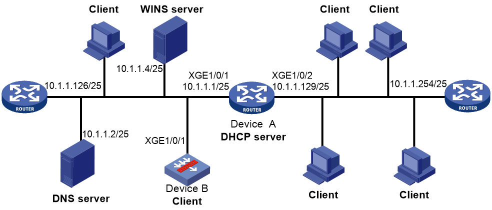
As shown in Figure 10, GigabitEthernet 1/0/1 of Device B connects to the LAN to obtain an IP address from the DHCP server by using BOOTP.
Procedure
The following describes the configuration on Device B, which acts as a client.
# Configure GigabitEthernet 1/0/1 to use BOOTP to obtain an IP address.
<DeviceB> system-view
[DeviceB] interface gigabitethernet 1/0/1
[DeviceB-GigabitEthernet1/0/1] ip address bootp-alloc
Verifying the configuration
# Display the IP address assigned to the BOOTP client.
[DeviceB] display bootp client