- Table of Contents
-
- 07-MPLS Configuration Guide
- 00-Preface
- 01-Basic MPLS configuration
- 02-Static LSP configuration
- 03-LDP configuration
- 04-MPLS TE configuration
- 05-Static CRLSP configuration
- 06-RSVP configuration
- 07-Tunnel policy configuration
- 08-MPLS L3VPN configuration
- 09-IPv6 MPLS L3VPN configuration
- 10-MPLS OAM configuration
- 11-MCE configuration
- Related Documents
-
| Title | Size | Download |
|---|---|---|
| 10-MPLS OAM configuration | 170.65 KB |
Contents
About LSP connectivity verification
Performing MPLS tracert for LSPs
Configuring control packet mode BFD for LSPs
Configuring echo packet mode BFD for LSPs
Configuring tunnel BFD for LSPs
Configuring periodic MPLS tracert for LSPs
Verifying MPLS TE tunnel connectivity
About MPLS TE tunnel connectivity verification
Performing MPLS ping for MPLS TE tunnels
Performing MPLS tracert for MPLS TE tunnels
Configuring BFD for MPLS TE tunnels (control packet mode)
Configuring BFD for MPLS TE tunnels (echo packet mode)
Configuring tunnel BFD for MPLS TE tunnels
Configuring SBFD for MPLS TE tunnels
Verifying and maintaining MPLS OAM
MPLS OAM configuration examples
Example: Configuring BFD for LSP
Configuring MPLS OAM
About MPLS OAM
· MPLS data plane connectivity verification.
· Data plane and control plane consistency verification.
· Fault locating.
Fault management tools
The fault management tools include the following types:
· On-demand tools—Tools that must be triggered manually, such as MPLS ping and MPLS tracert.
· Proactive tools—Tools that are triggered by the system automatically, such as BFD for MPLS, and periodic MPLS tracert.
You can use these tools to detect and locate faults of LSPs.
MPLS ping
MPLS ping tests the connectivity of an LSP tunnel or MPLS TE tunnel. At the ingress node, MPLS ping adds the label associated with a tunnel into an MPLS echo request and sends it to the egress node over the tunnel. The egress node processes the request and returns an MPLS echo reply to the ingress node. An MPLS echo reply with a success notification indicates that the tunnel is available for data forwarding. An MPLS echo reply with an error code indicates that the tunnel has failed.
MPLS tracert
MPLS tracert displays the path that an MPLS LSP tunnel or an MPLS TE tunnel travels from the ingress to the egress to locate errors on the tunnel. MPLS tracert consecutively sends MPLS echo requests along the LSP tunnel, with the TTL increasing from 1 to a specific value. Each hop along the tunnel returns an MPLS echo reply to the ingress due to TTL timeout so the ingress can collect information about each hop along the tunnel. This information allows you to locate the failed node or access information for each hop, for example, the label allocated by each downstream hop.
BFD for MPLS
BFD for MPLS uses a BFD session to proactively verify the connectivity of an LSP tunnel or an MPLS TE tunnel.
BFD can be implemented in control packet mode or echo packet mode. In echo packet mode, BFD for MPLS can verify the connectivity of only MPLS TE tunnels.
BFD control packet mode
In control packet mode, BFD for MPLS performs the following operations:
1. Establishes a BFD session between the ingress and egress of the tunnel to be inspected.
2. Adds the label associated with the tunnel into a BFD control packet at the ingress.
3. Sends the packet to the egress node over the tunnel.
4. Determines the tunnel status according to the BFD control packet returned by the egress.
When BFD detects a connectivity failure, it triggers the pre-configured action, such as FRR or path protection switching, to ensure uninterrupted traffic forwarding.
A BFD session for LSP or MPLS TE tunnel connectivity verification can be established in one of the following modes:
· Static mode—You manually specify the local and remote discriminators through command lines to establish the BFD session.
· Dynamic mode—The system automatically runs MPLS ping to negotiate the discriminators to establish the BFD session.
In static mode, the egress node returns a BFD control packet to the ingress node through the reverse tunnel. If no reverse tunnel exists, the ingress node cannot receive the BFD control packet, resulting in a verification failure.
In dynamic mode, the egress node returns a BFD control packet to the ingress node through the reverse tunnel. If no reverse tunnel exists, the egress mode returns a BFD packet through IP routing.
Use the static mode to test the connectivity of a pair of LSPs or MPLS TE tunnels in opposite directions between two devices. Use the dynamic mode to test the connectivity of one LSP or MPLS TE tunnel from the local device to the remote device.
BFD echo packet mode
In echo packet mode, BFD for MPLS performs the following operations:
1. Establishes a BFD session at the ingress of the tunnel to be inspected.
2. Adds the label associated with the tunnel into a BFD echo packet at the ingress.
3. Sends the echo packet to the egress node over the tunnel.
4. Without establishing a BFD session at the egress node, makes the egress node forward the echo packet back to the ingress node.
5. Determines the tunnel status according to whether the ingress node receives the BFD echo packet
SBFD for MPLS
SBFD for MPLS uses SBFD sessions to proactively verify the connectivity of LSP tunnels or or MPLS TE tunnels. When a tunnel fails, SBFD can quickly detect the failure and notify the device to take an action, such as switching traffic to the backup tunnel.
SBFD is unidirectional and quicker than BFD. SBFD verifies the connectivity of one tunnel from the local device to the remote device.
SBFD for MPLS performs the following operations:
1. Establishes an SBFD session between the ingress and egress nodes of the tunnel to be inspected.
2. Adds the label associated with the tunnel into an SBFD control packet at the ingress (the initiator).
3. Sends the control packet to the egress node (the reflector) over the tunnel.
4. Determines the tunnel status according to whether the ingress node receives the SBFD control response from the egress node.
An SBFD session can be established only in static mode. You must specify the remote discriminator values for the SBFD sessions.
Periodic MPLS tracert
The periodic MPLS tracert feature automatically traces an LSP tunnel at intervals. It locates errors on the LSP tunnel, verifies the consistency of the data plane and control plane, and records the detected errors in system logs. You can check the logs to monitor LSP connectivity.
If both BFD and periodic MPLS tracert are configured for an LSP, and the periodic tracert feature detects a data plane and control plane inconsistency, the device performs the following tasks:
1. Deletes the BFD session for the LSP.
2. Re-establishes the BFD session based on the control plane.
Protocols and standards
RFC 4379, Detecting Multi-Protocol Label Switched (MPLS) Data Plane Failures
Verifying LSP connectivity
About LSP connectivity verification
To verify LSP connectivity, you can use one of the following methods:
· Use the ping mpls ipv4 command or the tracert mpls ipv4 command to trigger LSP connectivity verification as needed.
· Configure BFD or periodic MPLS tracert for the system to automatically verify LSP connectivity.
Performing MPLS ping for LSPs
Pinging the LSPs for an IPv4 prefix
To verify MPLS LSP connectivity for an IPv4 prefix, execute the following command in any view:
ping mpls [ -a source-ip | -c count | -exp exp-value | -h ttl-value | -m wait-time | -r reply-mode | -rtos tos-value | -s packet-size | -t time-out | -v ] * ipv4 ipv4-address mask-length [ destination start-address [ end-address [ address-increment ] ] ] [ fec-type { generic | isis | ldp | ospf } ]
Pinging the LSPs of the specified outgoing labels
To verify MPLS LSP connectivity by specifying the outgoing labels, execute the following command in any view:
ping mpls [ -a source-ip | -c count | -exp exp-value | -h ttl-value | -m wait-time | -r reply-mode | -rtos tos-value | -s packet-size | -t time-out | -v ] * out-labels out-label-value&<1-n> interface interface-type interface-number [ nexthop nexthop-address ]
Performing MPLS tracert for LSPs
Tracing the path of the LSPs for an IPv4 prefix
To trace the path that the LSPs for an IPv4 prefix take from the ingress node to the egress node, execute the following command in any view:
tracert mpls [ -a source-ip | -exp exp-value | -h ttl-value | -r reply-mode | -rtos tos-value | -t time-out | -v | fec-check ] * ipv4 ipv4-address mask-length [ destination start-address [ end-address [ address-increment ] ] ] [ fec-type { generic | isis | ldp | ospf } ]
Tracing the path of the LSPs of the specified outgoing labels
To trace the path that the LSPs of the specified outgoing labels take from the ingress node to the egress node, execute the following command in any view:
tracert mpls [ -a source-ip | -exp exp-value | -h ttl-value | -r reply-mode | -rtos tos-value | -t time-out | -v | fec-check ]* out-labels out-label-value&<1-n> interface interface-type interface-number [ nexthop nexthop-address ]
Configuring control packet mode BFD for LSPs
Restrictions and guidelines
To configure BFD for an LSP, configure both the local and remote devices as described in Table 1.
Table 1 Configurations on the local and remote devices
|
BFD session establishment mode |
Node type |
Execute the "mpls bfd enable" command? |
Execute the "mpls bfd" command? |
Configure the discriminator keyword? |
|
Static mode |
Local |
Yes |
Yes |
Yes |
|
Remote |
Yes |
Yes |
Yes |
|
|
Dynamic mode |
Local |
Yes |
Yes |
No |
|
Remote |
Yes |
No |
N/A |
Follow these guidelines to configure BFD for an LSP tunnel:
· To establish a static BFD session, ensure that the local and remote discriminators configured locally are identical with the remote and local discriminators configured on the remote device, respectively.
· On a BFD session established in static mode, the ingress node and egress node both operate in active mode. On a BFD session established in dynamic mode, the egress node operates in active mode and the ingress node operates in passive mode. Executing the bfd session init-mode command on the ingress or egress node does not change the node's operating mode.
Prerequisites
The source address of the BFD session is the MPLS LSR ID of the local device. Before configuring BFD for the LSP tunnel, perform the following tasks:
1. Configure an MPLS LSR ID for the local device.
2. Make sure a route is available on the remote device to reach the MPLS LSR ID.
Procedure
1. Enter system view.
system-view
2. Enable BFD for MPLS.
mpls bfd enable
By default, BFD for MPLS is disabled.
3. (Optional.) Remove the Router Alert option in BFD packets.
undo bfd ip-router-alert
By default, the Router Alert option is carried in BFD packets for LSP connectivity verification.
Execute this command on the local device if the peer device cannot identify the Router Alert option in BFD packets.
This command takes effect only on BFD sessions that come up after this command is executed.
4. Configure BFD to verify LSP connectivity for an FEC.
mpls bfd dest-addr mask-length [ nexthop nexthop-address [ discriminator local local-id remote remote-id ] ] [ template template-name ]
By default, BFD is not configured to verify LSP connectivity for an FEC.
If you specify the next hop of an LSP, the device creates a BFD session for the LSP. If you do not specify a next hop, the device creates BFD sessions for all LSPs destined for the FEC.
You cannot specify the next hop of an LSP when configuring nested LSP connectivity verification.
Configuring echo packet mode BFD for LSPs
Restrictions and guidelines
If both BFD and FRR are enabled for an LSP, set the BFD detection interval for LSP connectivity verification to be longer than that for FRR. Otherwise, the BFD session for LSP connectivity verification will be down during an FRR switchover.
Prerequisites
The source address of the BFD session is the MPLS LSR ID of the local device. Before configuring BFD for the LSP tunnel, perform the following tasks:
1. Configure an MPLS LSR ID for the local device.
2. Make sure a route is available on the remote device to reach the MPLS LSR ID.
To enable the BFD echo packet mode, you must first execute the bfd echo-source-ip command on the local device to specify a source IP address for BFD echo packets.
Procedure
1. Enter system view.
system-view
2. Enable BFD for MPLS.
mpls bfd enable
By default, BFD for MPLS is disabled.
3. Configure echo packet mode BFD to verify LSP connectivity.
mpls bfd dest-addr mask-length nexthop nexthop-address echo [ template template-name ]
mpls bfd dest-addr mask-length echo [ template template-name ]
By default, echo packet mode BFD is not configured to verify LSP connectivity.
Configuring tunnel BFD for LSPs
About this task
The mpls bfd command can detect only the primary LSP failure. When the primary LSP fails, BFD can quickly detect the failure and notify the device to switch traffic to the backup LSP. When both the primary and backup LSPs fail, the BFD detection mechanism fails. Traffic is lost until another mechanism detects the failures and triggers a traffic protection measure (such as MPLS L3VPN ECMP route based load balancing and FRR).
To resolve this issue, you can execute the mpls tunnel-bfd command to configure tunnel BFD, which detects failures on the primary LSP and all the backup LSPs. When both the primary LSP and current backup LSP fail, tunnel BFD can quickly detect the failures and trigger a traffic protection measure to switch traffic to an available backup LSP.
Restrictions and guidelines
To configure tunnel BFD for an LSP, configure both the local and remote devices as described in Table 2.
Table 2 Configurations on the local and remote devices
|
BFD session establishment mode |
Node type |
Execute the "mpls bfd enable" command? |
Execute the "mpls tunnel-bfd" command? |
Configure the discriminator keyword? |
|
Static mode |
Local |
Yes |
Yes |
Yes |
|
Remote |
Yes |
Yes |
Yes |
|
|
Dynamic mode |
Local |
Yes |
Yes |
No |
|
Remote |
Yes |
No |
N/A |
Follow these guidelines to configure tunnel BFD for an LSP tunnel:
· To establish a static BFD session, ensure that the local and remote discriminators configured locally are identical with the remote and local discriminators configured on the remote device, respectively.
· On a BFD session established in static mode, the ingress node and egress node both operate in active mode. On a BFD session established in dynamic mode, the egress node operates in active mode and the ingress node operates in passive mode. Executing the bfd session init-mode command on the ingress or egress node does not change the node's operating mode.
Prerequisites
The source address of the BFD session is the MPLS LSR ID of the local device. Before configuring tunnel BFD for the LSP tunnel, perform the following tasks:
· Configure an MPLS LSR ID for the local device.
· Make sure a route is available on the remote device to reach the MPLS LSR ID.
Configuring control packet mode tunnel BFD for LSPs
1. Enter system view.
system-view
2. Enable BFD for MPLS.
mpls bfd enable
By default, BFD for MPLS is disabled.
3. (Optional.) Remove the Router Alert option in BFD packets.
undo bfd ip-router-alert
By default, the Router Alert option is carried in BFD packets for LSP connectivity verification.
Execute this command on the local device if the peer device cannot identify the Router Alert option in BFD packets.
This command takes effect only on BFD sessions that come up after this command is executed.
4. Configure control packet mode tunnel BFD to verify LSP connectivity for an FEC.
¡ To use a static BFD session:
mpls tunnel-bfd dest-addr mask-length discriminator local local-id remote remote-id [ template template-name ]
¡ To use a dynamic BFD session:
mpls tunnel-bfd dest-addr mask-length [ template template-name ]
By default, tunnel BFD is not configured to verify LSP connectivity for an FEC.
Configuring echo packet mode tunnel BFD for LSPs
1. Enter system view.
system-view
2. Enable BFD for MPLS.
mpls bfd enable
By default, BFD for MPLS is disabled.
3. (Optional.) Remove the Router Alert option in BFD packets.
undo bfd ip-router-alert
By default, the Router Alert option is carried in BFD packets for LSP connectivity verification.
Execute this command on the local device if the peer device cannot identify the Router Alert option in BFD packets.
This command takes effect only on BFD sessions that come up after this command is executed.
4. Configure echo packet mode tunnel BFD to verify LSP connectivity for an FEC.
mpls tunnel-bfd dest-addr mask-length echo [ template template-name ]
By default, tunnel BFD is not configured to verify LSP connectivity for an FEC.
Configuring SBFD for LSPs
Restrictions and guidelines
Perform this task on the SBFD session initiator. On the reflector, you must configure the sbfd local-discriminator command. Make sure the remote discriminator value configured on the initiator is the same as a local discriminator value configured on the reflector. If the two ends do not have a matching discriminator value, the reflector does not send responses to the initiator. For more information about the sbfd local-discriminator command, see High Availability Command Reference.
Prerequisites
The source address of the SBFD session is the MPLS LSR ID of the local device. Before configuring SBFD for an LSP tunnel, perform the following tasks:
1. Configure an MPLS LSR ID for the local device.
2. Make sure a route is available on the remote device to reach the MPLS LSR ID.
Configuring the initiator
1. Enter system view.
system-view
2. Enable BFD for MPLS.
mpls bfd enable
By default, BFD for MPLS is disabled.
3. Configure SBFD to verify LSP connectivity for an FEC.
mpls sbfd dest-addr mask-length [ nexthop nexthop-address ] remote remote-id [ template template-name ]
By default, SBFD is not configured to verify LSP connectivity for an FEC.
Configuring periodic MPLS tracert for LSPs
1. Enter system view.
system-view
2. Enable BFD for MPLS.
mpls bfd enable
By default, BFD for MPLS is disabled.
3. Enable periodic LSP tracert for an FEC.
mpls periodic-tracert dest-addr mask-length [ -a source-ip | -exp exp-value | -h ttl-value | -m wait-time | -rtos tos-value | -t time-out | -u retry-attempt | fec-check ] *
By default, periodic LSP tracert is disabled.
Verifying MPLS TE tunnel connectivity
About MPLS TE tunnel connectivity verification
To verify MPLS TE tunnel connectivity, you can use one of the following methods:
· Use ping mpls te command or the tracert mpls te command to trigger MPLS TE tunnel connectivity verification as needed.
· Configure BFD for the system to automatically verify MPLS TE tunnel connectivity.
Performing MPLS ping for MPLS TE tunnels
To use MPLS ping to verify MPLS TE tunnel connectivity, execute the following command in any view:
ping mpls [ -a source-ip | -c count | -exp exp-value | -h ttl-value | -m wait-time | -r reply-mode | -rtos tos-value | -s packet-size | -t time-out | -v ] * te tunnel interface-number
Performing MPLS tracert for MPLS TE tunnels
To use MPLS tracert to trace an MPLS TE tunnel, execute the following command in any view:
tracert mpls [ -a source-ip | -exp exp-value | -h ttl-value | -r reply-mode | -rtos tos-value | -t time-out | -v | fec-check ] * te tunnel interface-number
Configuring BFD for MPLS TE tunnels (control packet mode)
About this task
This feature enables the device to create a BFD session for each CRLSP on the tunnel interface. When a CRLSP fails, BFD can quickly detect the failure and notify the device to take an action, such as switching traffic to the other CRLSP. If the two CRLSPs fail at the same time, the device puts the MPLS TE tunnel to down state so the tunnel does not receive traffic.
Restrictions and guidelines
To run BFD on an MPLS TE tunnel, configure both the local and remote devices as described in Table 3.
Table 3 Configurations on the local and remote devices
|
BFD session establishment mode |
Node type |
Execute the "mpls bfd enable" command? |
Execute the "mpls bfd" command? |
Configure the discriminator keyword? |
|
Static mode |
Local |
Yes |
Yes |
Yes |
|
Remote |
Yes |
Yes |
Yes |
|
|
Dynamic mode |
Local |
Yes |
Yes |
No |
|
Remote |
Yes |
No |
N/A |
Follow these guidelines to configure BFD for an MPLS TE tunnel:
· To establish a static BFD session, ensure that the local and remote discriminators configured locally are identical with the remote and local discriminators configured on the remote device, respectively.
· On a BFD session established in static mode, the ingress node and egress node both operate in active mode. On a BFD session established in dynamic mode, the egress node operates in active mode and the ingress node operates in passive mode. Executing the bfd session init-mode command on the ingress or egress node does not change the node's operating mode.
· If both BFD and FRR are enabled for an MPLS TE tunnel, set the BFD detection interval for tunnel connectivity verification to be longer than that for FRR. Otherwise, the BFD session for MPLS TE tunnel connectivity verification will be down during an FRR switchover.
· If the primary path of an MPLS TE tunnel fails, the BFD session state for the MPLS TE tunnel becomes down. Then, the device establishes a BFD session for the MPLS TE tunnel based on the backup path. After the BFD session is established successfully, the BFD session state for the MPLS TE tunnel becomes up.
Prerequisites
The source address of the BFD session is the MPLS LSR ID of the local device. Before configuring BFD for the LSP tunnel, perform the following tasks:
· Configure an MPLS LSR ID for the local device.
· Make sure a route is available on the remote device to reach the MPLS LSR ID.
Procedure
1. Enter system view.
system-view
2. Enable BFD for MPLS.
mpls bfd enable
By default, BFD for MPLS is disabled.
3. (Optional.) Enable dynamic establishment of passive mode BFD sessions.
mpls bfd passive enable
By default, device can dynamically establish passive mode BFD sessions.
This command is required only on the egress node to establish a dynamic BFD session.
4. Enter the view of an MPLS TE tunnel interface.
interface tunnel number
5. (Optional.) Configure the control packet mode BFD parameters for MPLS TE primary tunnel connectivity verification.
¡ Set the BFD detection time multiplier for the primary tunnel.
mpls bfd detect-multiplier value
By default, the BFD detection time multiplier is not set.
¡ Set the minimum interval for the primary tunnel to receive BFD packets.
mpls bfd min-receive-interval interval
By default, the minimum receive interval is not set.
¡ Set the minimum interval for the primary tunnel to transmit BFD packets.
mpls bfd min-transmit-interval interval
By default, the minimum transmit interval is not set.
6. (Optional.) Configure the control packet mode BFD parameters for MPLS TE backup tunnel connectivity verification.
¡ Set the BFD detection time multiplier for the backup tunnel.
mpls bfd backup detect-multiplier value
By default, the BFD detection time multiplier is not set.
¡ Set the minimum interval for the backup tunnel to receive BFD packets.
mpls bfd backup min-receive-interval interval
By default, the minimum receive interval is not set.
¡ Set the minimum interval for the backup tunnel to transmit BFD packets.
mpls bfd backup min-transmit-interval interval
By default, the minimum transmit interval is not set.
7. Configure the BFD control packet mode to verify MPLS TE tunnel connectivity.
mpls bfd [ discriminator local local-id remote remote-id ] [ template template-name ] [ backup-path template template-name ]
By default, the BFD control packet mode is not configured to verify MPLS TE tunnel connectivity.
If you specify a template for each CRLSP, specify greater interval settings for the template of the backup CRLSP than the primary CRLSP. This rule ensures that the BFD session for the new primary CRLSP is up after a primary/backup CRLSP switchover.
Configuring BFD for MPLS TE tunnels (echo packet mode)
Restrictions and guidelines
If both BFD and FRR are enabled for an MPLS TE tunnel, set the BFD detection interval for tunnel connectivity verification to be longer than that for FRR. Otherwise, the BFD session for MPLS TE tunnel connectivity verification will be down during an FRR switchover.
If the primary path of an MPLS TE tunnel fails, the BFD session state for the MPLS TE tunnel becomes down. Then, the device establishes a BFD session for the MPLS TE tunnel based on the backup path. After the BFD session is established successfully, the BFD session state for the MPLS TE tunnel becomes up.
Prerequisites
· The source address of the BFD session is the MPLS LSR ID of the local device. Before configuring BFD for the LSP tunnel, perform the following tasks:
¡ Configure an MPLS LSR ID for the local device.
¡ Make sure a route is available on the remote device to reach the MPLS LSR ID.
· Configure the bfd echo-source-ip command on the local device to specify a source IP address for echo packets.
Procedure
1. Enter system view.
system-view
2. Enable BFD for MPLS.
mpls bfd enable
By default, BFD for MPLS is disabled.
3. Enter the view of an MPLS TE tunnel interface.
interface tunnel number
4. (Optional.) Configure the echo packet mode BFD parameters for MPLS TE primary tunnel connectivity verification.
¡ Set the minimum interval for the primary tunnel to receive BFD packets.
mpls bfd min-receive-interval interval
By default, the minimum receive interval is not set.
5. (Optional.) Configure the echo packet mode BFD parameters for MPLS TE backup tunnel connectivity verification.
¡ Set the minimum interval for the backup tunnel to receive BFD packets.
mpls bfd backup min-receive-interval interval
By default, the minimum receive interval is not set.
6. Enable the BFD echo packet mode to verify MPLS TE tunnel connectivity.
mpls bfd echo [ template template-name ] [ backup-path template template-name ]
By default, the BFD echo packet mode is not configured to verify MPLS TE tunnel connectivity.
If you specify a template for each CRLSP, specify greater interval settings for the template of the backup CRLSP than the primary CRLSP. This rule ensures that the BFD session for the new primary CRLSP is up after a primary/backup CRLSP switchover.
Configuring tunnel BFD for MPLS TE tunnels
About this task
In an MPLS TE CRLSP backup scenario, you can use the mpls bfd command to create a BFD session for the primary and backup CRLSPs, respectively. When the primary CRLSP fails, BFD can quickly detect the failure and notify the device to switch traffic to the backup CRLSP. When both the primary and backup CRLSPs fail, the BFD detection mechanism fails. Traffic is lost until another mechanism detects the failure and triggers a traffic protection measure (such as MPLS L3VPN ECMP route based load balancing and FRR) to take effect.
To resolve this issue, you can execute the mpls tunnel-bfd command to configure tunnel BFD, which detects failures on the primary CRLSP and all the backup CRLSPs. When both the primary CRLSP and the current backup CRLSP fail, tunnel BFD can quickly detect the failures and trigger a traffic protection measure to switch traffic to an available backup CRLSP.
Restrictions and guidelines
To run tunnel BFD on an MPLS TE tunnel, configure both the local and remote devices as described in Table 4.
Table 4 Configurations on the local and remote devices
|
BFD session establishment mode |
Node type |
Execute the "mpls bfd enable" command? |
Execute the "mpls tunnel-bfd" command? |
Configure the discriminator keyword? |
|
Static mode |
Local |
Yes |
Yes |
Yes |
|
Remote |
Yes |
Yes |
Yes |
|
|
Dynamic mode |
Local |
Yes |
Yes |
No |
|
Remote |
Yes |
No |
N/A |
Follow these guidelines to configure tunnel BFD for an MPLS TE tunnel:
· To establish a static BFD session, ensure that the local and remote discriminators configured locally are identical with the remote and local discriminators configured on the remote device, respectively.
· On a BFD session established in static mode, the ingress node and egress node both operate in active mode. On a BFD session established in dynamic mode, the egress node operates in active mode and the ingress node operates in passive mode. Executing the bfd session init-mode command on the ingress or egress node does not change the node's operating mode.
Prerequisites
The source address of the BFD session is the MPLS LSR ID of the local device. Before configuring BFD for the LSP tunnel, perform the following tasks:
· Configure an MPLS LSR ID for the local device.
· Make sure a route is available on the remote device to reach the MPLS LSR ID.
To enable the BFD echo packet mode, you must first configure the bfd echo-source-ip command on the local device to specify a source IP address for BFD echo packets.
Configuring control packet mode tunnel BFD for an MPLS TE tunnel
1. Enter system view.
system-view
2. Enable BFD for MPLS.
mpls bfd enable
By default, BFD for MPLS is disabled.
3. (Optional.) Enable dynamic establishment of passive mode BFD sessions.
mpls bfd passive enable
By default, device can dynamically estalbish passive mode BFD sessions.
This command is required only on the egress node to establish a dyamic BFD session.
4. Enter the view of an MPLS TE tunnel interface.
interface tunnel number
5. Configure control packet mode tunnel BFD to verify MPLS TE tunnel connectivity.
¡ To use a static BFD session:
mpls tunnel-bfd discriminator local local-id remote remote-id [ template template-name ]
¡ To use a dynamic BFD session:
mpls tunnel-bfd [ template template-name ]
By default, tunnel BFD is not configured to verify MPLS TE tunnel connectivity.
If you specify templates for both BFD and tunnel BFD, specify greater interval settings for the BFD template than the tunnel BFD template. This rule ensures that the tunnel BFD session for MPLS TE tunnel is up after a primary/backup LSP switchover.
command on the local device to specify a source IP address for BFD echo packets.
Configuring echo packet mode tunnel BFD for an MPLS TE tunnel
1. Enter system view.
system-view
2. Enable BFD for MPLS.
mpls bfd enable
By default, BFD for MPLS is disabled.
3. (Optional.) Enable dynamic establishment of passive mode BFD sessions.
mpls bfd passive enable
By default, device can dynamically estalbish passive mode BFD sessions.
This command is required only on the egress node to establish a dyamic BFD session.
4. Enter the view of an MPLS TE tunnel interface.
interface tunnel number
5. Configure echo packet mode tunnel BFD to verify MPLS TE tunnel connectivity.
mpls tunnel-bfd echo [ template template-name ]
By default, tunnel BFD is not configured to verify MPLS TE tunnel connectivity.
If you specify templates for both BFD and tunnel BFD, specify greater interval settings for the BFD template than the tunnel BFD template. This rule ensures that the tunnel BFD session for MPLS TE tunnel is up after a primary/backup LSP switchover.
Configuring SBFD for MPLS TE tunnels
Restrictions and guidelines
Perform this task on the initiator of an SBFD session. On the reflector of the session, specify a local discriminator by using the sbfd local-discriminator command. For more information about the sbfd local-discriminator command, see BFD configuration in High Reliability Configuration Guide.
The remote discriminator specified on the initiator must be the same as the local discriminator specified on the reflector. Otherwise, the reflector will not respond to the initiator.
Prerequisites
The source address of the SBFD session is the MPLS LSR ID of the local device. Before configuring SBFD for the MPLS TE tunnel, perform the following tasks:
· Configure an MPLS LSR ID for the local device.
· Make sure a route is available on the remote device to reach the MPLS LSR ID.
Procedure
1. Enter system view.
system-view
2. Enable BFD for MPLS.
mpls bfd enable
By default, BFD for MPLS is disabled.
3. Enter the view of an MPLS TE tunnel interface.
interface tunnel number
4. Configure SBFD to verify MPLS TE tunnel connectivity.
mpls sbfd remote remote-id [ template template-name ]
By default, SBFD is not configured to verify MPLS TE tunnel connectivity.
Verifying and maintaining MPLS OAM
Perform display tasks in any view.
· Display BFD information for LSP tunnels.
display mpls bfd [ ipv4 ipv4-address mask-length | te tunnel tunnel-number ]
· Display SBFD information for LSP tunnels.
display mpls sbfd [ ipv4 ipv4-address mask-length | sr-policy [ end-point ipv4 ip-address color color-value | name sr-policy-name ] | te tunnel tunnel-number ]
MPLS OAM configuration examples
Example: Configuring BFD for LSP
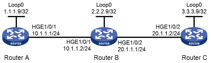
Network configuration
Use LDP to establish an LSP from 1.1.1.9/32 to 3.3.3.9/32 and an LSP from 3.3.3.9/32 to 1.1.1.9/32. Use BFD to verify LSP connectivity.
Figure 1 Network diagram
Prerequisites
By default, interfaces on the device are disabled (in ADM or Administratively Down state). To have an interface operate, you must use the undo shutdown command to enable that interface.
Procedure
1. Configure IP addresses for interfaces. (Details not shown.)
2. Configure OSPF to ensure IP connectivity between the routers:
# Configure Router A.
<RouterA> system-view
[RouterA] ospf
[RouterA-ospf-1] area 0
[RouterA-ospf-1-area-0.0.0.0] network 1.1.1.9 0.0.0.0
[RouterA-ospf-1-area-0.0.0.0] network 10.1.1.0 0.0.0.255
[RouterA-ospf-1-area-0.0.0.0] quit
[RouterA-ospf-1] quit
# Configure Router B.
<RouterB> system-view
[RouterB] ospf
[RouterB-ospf-1] area 0
[RouterB-ospf-1-area-0.0.0.0] network 2.2.2.9 0.0.0.0
[RouterB-ospf-1-area-0.0.0.0] network 10.1.1.0 0.0.0.255
[RouterB-ospf-1-area-0.0.0.0] network 20.1.1.0 0.0.0.255
[RouterB-ospf-1-area-0.0.0.0] quit
[RouterB-ospf-1] quit
# Configure Router C.
<RouterC> system-view
[RouterC] ospf
[RouterC-ospf-1] area 0
[RouterC-ospf-1-area-0.0.0.0] network 3.3.3.9 0.0.0.0
[RouterC-ospf-1-area-0.0.0.0] network 20.1.1.0 0.0.0.255
[RouterC-ospf-1-area-0.0.0.0] quit
[RouterC-ospf-1] quit
3. Enable MPLS and LDP:
# Configure Router A.
[RouterA] mpls lsr-id 1.1.1.9
[RouterA] mpls ldp
[RouterA-ldp] quit
[RouterA] interface hundredgige 1/0/1
[RouterA-HundredGigE1/0/1] mpls enable
[RouterA-HundredGigE1/0/1] mpls ldp enable
[RouterA-HundredGigE1/0/1] quit
# Configure Router B.
[RouterB] mpls lsr-id 2.2.2.9
[RouterB] mpls ldp
[RouterB-ldp] quit
[RouterB] interface hundredgige 1/0/1
[RouterB-HundredGigE1/0/1] mpls enable
[RouterB-HundredGigE1/0/1] mpls ldp enable
[RouterB-HundredGigE1/0/1] quit
[RouterB] interface hundredgige 1/0/2
[RouterB-HundredGigE1/0/2] mpls enable
[RouterB-HundredGigE1/0/2] mpls ldp enable
[RouterB-HundredGigE1/0/2] quit
# Configure Router C.
[RouterC] mpls lsr-id 3.3.3.9
[RouterC] mpls ldp
[RouterC-ldp] quit
[RouterC] interface hundredgige 1/0/2
[RouterC-HundredGigE1/0/2] mpls enable
[RouterC-HundredGigE1/0/2] mpls ldp enable
[RouterC-HundredGigE1/0/2] quit
4. Enable BFD for MPLS, and configure BFD to verify LSP connectivity:
# Configure Router A.
[RouterA] mpls bfd enable
[RouterA] mpls bfd 3.3.3.9 32
# Configure Router C.
[RouterC] mpls bfd enable
[RouterC] mpls bfd 1.1.1.9 32
Verifying the configuration
# Display BFD information for LSPs on Router A and Router C, for example, on Router A.
[RouterA] display mpls bfd
Total number of sessions: 2, 2 up, 0 down, 0 init
FEC Type: LSP
FEC Info:
Destination: 1.1.1.9
Mask Length: 32
NHLFE ID: -
Local Discr: 513 Remote Discr: 513
Source IP: 1.1.1.9 Destination IP: 3.3.3.9
Session State: Up Session Role: Active
Template Name: -
FEC Type: LSP
FEC Info:
Destination: 3.3.3.9
Mask Length: 32
NHLFE ID: 1042
Local Discr: 514 Remote Discr: 514
Source IP: 1.1.1.9 Destination IP: 127.0.0.1
Session State: Up Session Role: Passive
Template Name: -
The output shows that two BFD sessions have been established between Router A and Router C. One session verifies the connectivity of the LSP from 3.3.3.9/32 to 1.1.1.9/32, and the other session verifies the connectivity of the LSP from 1.1.1.9/32 to 3.3.3.9/32.
