- Table of Contents
-
- 07-MPLS Configuration Guide
- 00-Preface
- 01-Basic MPLS configuration
- 02-Static LSP configuration
- 03-LDP configuration
- 04-MPLS TE configuration
- 05-Static CRLSP configuration
- 06-RSVP configuration
- 07-Tunnel policy configuration
- 08-MPLS L3VPN configuration
- 09-IPv6 MPLS L3VPN configuration
- 10-MPLS OAM configuration
- 11-MCE configuration
- Related Documents
-
| Title | Size | Download |
|---|---|---|
| 07-Tunnel policy configuration | 401.80 KB |
Tunnel policy application scenario
Restrictions and guidelines: Tunnel policy configuration
Configuring a bound tunnel policy
Configuring a preferred tunnel policy
Configuring a load sharing policy
Verifying and maintaining tunnel policies
Tunnel policy configuration examples
Example: Configuring exclusive tunnels
Example: Configuring bound tunnels in a tunnel policy
Example: Configuring preferred tunnels and tunnel selection order
Tunnel selector implementation
Tunnel selector tasks at a glance
Configuring an IPv4 prefix list
Configuring an IPv6 prefix list
Applying a tunnel policy to a tunnel selector
Display and maintenance commands for tunnel selector
Tunnel selector configuration examples
Example: Configuring tunnel selectors for MPLS L3VPN inter-AS option B
Example: Configuring tunnel selectors for MPLS L3VPN inter-AS option C
Example: Configuring tunnel selectors for HoVPN
Example: Configuring tunnel selectors for IPv6 MPLS L3VPN inter-AS option B
Configuring tunnel policies
About tunnel policies
Tunnel policies enable a PE to forward traffic for each MPLS VPN over a preferred tunnel or load share the traffic over multiple tunnels. Using tunnel policies can facilitate network planning and management and reduce processing overhead on PEs.
For more information about MPLS VPN, see "Configuring MPLS L3VPN."
Tunnel policy implementation
Bound tunnel
You can bind a destination IP address to one or more tunnels in a tunnel policy. After the tunnel policy is applied to a VPN, the VPN traffic to the destination IP address will be forwarded by the bound tunnels.
Preferred tunnel
You can specify a tunnel as a preferred tunnel in a tunnel policy. If the destination address of the tunnel interface identifies a peer PE, the policy will forward traffic destined for that peer PE over the preferred tunnel.
If multiple preferred tunnels that have the same destination address are specified in a tunnel policy, the policy uses the following procedure to select a preferred tunnel:
1. The policy selects the first configured preferred tunnel.
2. If the first configured tunnel is not available, the policy selects the second tunnel, and so forth.
Since the policy uses only one tunnel, no load sharing will be performed on these tunnels. This method explicitly specifies a tunnel for an MPLS VPN, facilitating traffic planning. As a best practice, use this method.
Load sharing
You can configure tunnel load sharing by specifying the tunnel selection order and the number of tunnels for load sharing in a tunnel policy.
This method distributes traffic of a single VPN to multiple tunnels. The transmission delays on different tunnels can vary greatly. Therefore, the destination device or the upper layer application might take a great time to sequence the packets. As a best practice, do not use this method.
Tunnel selection rule
If you use all the bound tunnel, preferred tunnel, and load sharing methods for a tunnel policy, the tunnel policy selects tunnels as follows:
· If the destination address of a bound tunnel identifies a peer PE, the tunnel policy uses the bound tunnel to forward the traffic to the peer PE.
For an SR-MPLS TE policy group, the tunnel destination address is the destination node's address of the SR-MPLS TE policy group.
· If no bound tunnels are available for the peer PE, the tunnel policy selects a preferred tunnel whose destination address can identify the peer PE to forward traffic.
· If no preferred tunnel is available for the peer PE, the tunnel policy uses the load sharing method to forward the traffic to the peer PE.
Supported tunnel types
Tunnel policies support the following tunnel types:
· MPLS TE tunnels. For more information about MPLS TE tunnels, see "Configuring MPLS TE."
· MPLS LSPs. Only the load sharing method supports using MPLS LSPs.
· SR-MPLS TE policy group tunnels. For more information, see the SR-MPLS TE policy configuration in Segment Routing Configuration Guide.
Tunnel policy application scenario
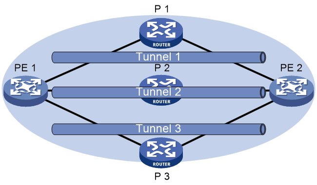
As shown in Figure 1, PE 1 and PE 2 have multiple tunnels in between and they are connected to multiple MPLS VPNs. You can control the paths for VPN traffic by using one of the following methods:
· Bound tunnel—Configure one tunnel policy, and specify different bound tunnels for different destination addresses of an MPLS VPN in the tunnel policy. Apply the tunnel policy to the MPLS VPN to forward the traffic of different destination addresses in the VPN over different tunnels.
· Preferred tunnel—Configure multiple tunnel policies, and specify a preferred tunnel for each policy. Apply these policies to different MPLS VPNs to forward the traffic of each VPN over a specific tunnel.
· Load sharing—Configure one tunnel policy, and specify the tunnel selection order and the number of tunnels for load sharing. Apply the tunnel policy to MPLS VPNs to forward the traffic of every VPN over multiple tunnels.
Figure 1 Tunnel policy application scenario
Restrictions and guidelines: Tunnel policy configuration
To configure a VPN to exclusively use a tunnel, perform the following operations:
1. Use the preferred-path command to specify the tunnel as the preferred tunnel in a tunnel policy.
2. Apply the policy only to that VPN.
Configuring a bound tunnel policy
1. Enter system view.
system-view
2. Enter the tunnel interface view of an MPLS TE tunnel.
interface tunnel number mode mpls-te
3. Reserve the MPLS TE tunnel for bound tunnels.
mpls te reserved-for-binding
By default, an MPLS TE tunnel can be used by any tunnel policy implementation methods.
To bind an MPLS TE tunnel in a tunnel policy, you must execute this command for this tunnel.
4. Return to system view.
quit
5. Create a tunnel policy and enter tunnel policy view.
tunnel-policy tunnel-policy-name [ default ]
6. Bind tunnels to a destination IP address, so the tunnels can be used only for a specific VPN service.
binding-destination dest-ip-address { sr-policy group sr-policy-group-id | te { tunnel number }&<1-16> } [ ignore-destination-check ] [ down-switch ]
By default, a tunnel policy does not bind tunnels to a destination IP address.
You can bind tunnels to multiple destination IP addresses in a tunnel policy.
Configuring a preferred tunnel policy
1. Enter system view.
system-view
2. Create a tunnel policy and enter tunnel policy view.
tunnel-policy tunnel-policy-name [ default ]
3. Configure a tunnel or a tunnel bundle as a preferred tunnel.
preferred-path { tunnel number | tunnel-bundle number }
By default, no preferred tunnels are configured.
To enhance availability, you can associate multiple MPLS TE tunnels to a tunnel bundle, and specify the tunnel bundle as a preferred tunnel.
Configuring a load sharing policy
1. Enter system view.
system-view
2. Create a tunnel policy and enter tunnel policy view.
tunnel-policy tunnel-policy-name [ default ]
3. Configure the tunnel selection order and the number of tunnels for load sharing.
select-seq [ strict ] { cr-lsp | lsp | sr-lsp | sr-policy } * load-balance-number number
By default, the policy selects only one tunnel in LSP, CRLSP, SRLSP, and SR-MPLS TE policy order.
Verifying and maintaining tunnel policies
To display tunnel information, execute the following command in any view:
display mpls tunnel { all | statistics | [ vpn-instance vpn-instance-name ] destination { ipv4-address | ipv6-address } }
Tunnel policy configuration examples
Example: Configuring exclusive tunnels
Network configuration
PE 1 has multiple tunnels to reach PE 2: two MPLS TE tunnels on interface Tunnel 1 and Tunnel 2, and one LDP LSP tunnel.
Two MPLS VPNs, vpna and vpnb, exist on PE 1. The VPN vpna exclusively uses the MPLS TE tunnel 1, and the VPN vpnb exclusively uses the MPLS TE tunnel 2.
Prerequisites
By default, interfaces on the device are disabled (in ADM or Administratively Down state). To have an interface operate, you must use the undo shutdown command to enable that interface.
Procedure
1. Configure tunnel policies on PE 1:
# Create tunnel policy preferredte1, and configure tunnel 1 as the preferred tunnel.
<PE1> system-view
[PE1] tunnel-policy preferredte1
[PE1-tunnel-policy-preferredte1] preferred-path tunnel 1
[PE1-tunnel-policy-preferredte1] quit
# Create tunnel policy preferredte2, and configure tunnel 2 as the preferred tunnel.
[PE1] tunnel-policy preferredte2
[PE1-tunnel-policy-preferredte2] preferred-path tunnel 2
[PE1-tunnel-policy-preferredte2] quit
2. Configure MPLS VPN instances and apply tunnel policies to the VPN instances:
# Create MPLS VPN instance vpna, and apply tunnel policy preferredte1 to it.
[PE1] ip vpn-instance vpna
[PE1-vpn-instance-vpna] route-distinguisher 100:1
[PE1-vpn-instance-vpna] vpn-target 100:1
[PE1-vpn-instance-vpna] tnl-policy preferredte1
[PE1-vpn-instance-vpna] quit
# Create MPLS VPN instance vpnb, and apply tunnel policy preferredte2 to it.
[PE1] ip vpn-instance vpnb
[PE1-vpn-instance-vpnb] route-distinguisher 100:2
[PE1-vpn-instance-vpnb] vpn-target 100:2
[PE1-vpn-instance-vpnb] tnl-policy preferredte2
Example: Configuring bound tunnels in a tunnel policy
Network configuration
PE 1 has multiple tunnels to reach PE 2, including two MPLS TE tunnels. An MPLS VPN exists on PE 1. Configure a tunnel policy, so the two MPLS TE tunnels are only used to forward traffic for that VPN.
Prerequisites
By default, interfaces on the device are disabled (in ADM or Administratively Down state). To have an interface operate, you must use the undo shutdown command to enable that interface.
Procedure
1. Reserve the MPLS TE tunnels only for bound tunnels:
# Reserve MPLS TE tunnel 1 for bound tunnels.
<PE1> system-view
[PE1] interface tunnel 1 mode mpls-te
[PE1-Tunnel1] mpls te reserved-for-binding
[PE1-Tunnel1] quit
# Reserve MPLS TE tunnel 2 for bound tunnels.
[PE1] interface tunnel 2 mode mpls-te
[PE1-Tunnel2] mpls te reserved-for-binding
[PE1-Tunnel2] quit
2. Configure a tunnel policy on PE 1.
# Create a tunnel policy named text, bind the MPLS TE tunnels to the IP address of the MP-BGP peer, so that the tunnels can forward traffic only for a specific VPN service.
<PE1> system-view
[PE1] tunnel-policy text
[PE1-tunnel-policy-text] binding-destination 2.2.2.2 te tunnel 1 tunnel 2
[PE1-tunnel-policy-text] quit
3. Create MPLS VPN instance vpna, and apply tunnel policy text to it.
[PE1] ip vpn-instance vpna
[PE1-vpn-instance-vpna] route-distinguisher 100:1
[PE1-vpn-instance-vpna] vpn-target 100:1
[PE1-vpn-instance-vpna] tnl-policy text
[PE1-vpn-instance-vpna] quit
Example: Configuring preferred tunnels and tunnel selection order
Network configuration
PE 1 has multiple tunnels to reach PE 2: two MPLS TE tunnels on interfaces Tunnel 1 and Tunnel 2, and one LDP LSP tunnel.
PE 1 has multiple MPLS VPN instances: vpna, vpnb, vpnc, vpnd, and vpne. Table 1 shows the tunnel policy that PE 1 uses for each VPN instance.
Table 1 Tunnel policies used for VPN instances
|
VPN instance |
Tunnel policy |
|
vpna, vpnb |
Use MPLS TE tunnel Tunnel 1 as the preferred tunnel. |
|
vpnc, vpnd |
Use MPLS TE tunnel Tunnel 2 as the preferred tunnel. |
|
vpne |
Uses one tunnel selected in LDP LSP-MPLS TE order. |
Prerequisites
By default, interfaces on the device are disabled (in ADM or Administratively Down state). To have an interface operate, you must use the undo shutdown command to enable that interface.
Procedure
1. Configure tunnel policies on PE 1:
# Create tunnel policy preferredte1, and configure tunnel 1 as the preferred tunnel.
<PE1> system-view
[PE1] tunnel-policy preferredte1
[PE1-tunnel-policy-preferredte1] preferred-path tunnel 1
[PE1-tunnel-policy-preferredte1] quit
# Create tunnel policy preferredte2, and configure tunnel 2 as the preferred tunnel.
[PE1] tunnel-policy preferredte2
[PE1-tunnel-policy-preferredte2] preferred-path tunnel 2
[PE1-tunnel-policy-preferredte2] quit
# Create tunnel policy select-lsp.
[PE1] tunnel-policy select-lsp
# Configure the policy to select only one tunnel in LDP LSP-MPLS TE order.
[PE1-tunnel-policy-select-lsp] select-seq lsp cr-lsp load-balance-number 1
[PE1-tunnel-policy-select-lsp] quit
2. Configure MPLS VPN instances and apply tunnel policies to the VPN instances:
# Create MPLS VPN instances vpna and vpnb, and apply tunnel policy preferredte1 to them.
[PE1] ip vpn-instance vpna
[PE1-vpn-instance-vpna] route-distinguisher 100:1
[PE1-vpn-instance-vpna] vpn-target 100:1
[PE1-vpn-instance-vpna] tnl-policy preferredte1
[PE1-vpn-instance-vpna] quit
[PE1] ip vpn-instance vpnb
[PE1-vpn-instance-vpnb] route-distinguisher 100:2
[PE1-vpn-instance-vpnb] vpn-target 100:2
[PE1-vpn-instance-vpnb] tnl-policy preferredte1
[PE1-vpn-instance-vpnb] quit
# Create MPLS VPN instances vpnc and vpnd, and apply tunnel policy preferredte2 to them.
[PE1] ip vpn-instance vpnc
[PE1-vpn-instance-vpnc] route-distinguisher 100:3
[PE1-vpn-instance-vpnc] vpn-target 100:3
[PE1-vpn-instance-vpnc] tnl-policy preferredte2
[PE1-vpn-instance-vpnc] quit
[PE1] ip vpn-instance vpnd
[PE1-vpn-instance-vpnd] route-distinguisher 100:4
[PE1-vpn-instance-vpnd] vpn-target 100:4
[PE1-vpn-instance-vpnd] tnl-policy preferredte2
[PE1-vpn-instance-vpnd] quit
# Create MPLS VPN instance vpne, and apply tunnel policy select-lsp to it.
[PE1] ip vpn-instance vpne
[PE1-vpn-instance-vpne] route-distinguisher 100:5
[PE1-vpn-instance-vpne] vpn-target 100:5
[PE1-vpn-instance-vpne] tnl-policy select-lsp
Configuring tunnel selectors
About tunnel selectors
On an MPLS L3VPN network, a tunnel policy is applied to a VPN instance. All routes of the VPN instance recurse to specific types of tunnels according to the tunnel policy. If no tunnel policy is applied to a VPN instance, the VPNv4, VPNv6, or BGP labeled routes recurse to LSP tunnels by default.
Tunnel policies cannot be used in the following scenarios:
· In an inter-AS Option B network, an ASBR receives VPNv4 or VPNv6 routes from all PEs. To guarantee bandwidth, you might want these routes to recurse to MPLS TE tunnels. However, if you do not want to create VPN instances on the ASBR, you cannot apply a tunnel policy to select MPLS TE tunnels.
· In an inter-AS Option C network, the local PE receives BGP labeled routes. To guarantee bandwidth for tunnels, you want the labeled routes to recurse to MPLS TE tunnels. However, the system cannot achieve this purpose simply by using a tunnel policy.
To resolve these issues, you can configure tunnel selectors. A tunnel selector specifies a tunnel policy and defines route filters, which can filter BGP VPNv4 routes, BGP VPNv6 route, or labeled BGP IPv4 or IPv6 unicast routes. The specified tunnel policy is applied to the matching routes to select the expected types of tunnels.
Tunnel selector implementation
To apply a tunnel selector, perform the following tasks:
1. Create the tunnel selector.
2. Configure filters to match the routes to which the tunnel selector will be applied.
3. Specify a tunnel policy for the tunnel selector.
The tunnel selector applies the specified tunnel policy to the matching routes.
Filters
Tunnel selectors use filters to filter routes.
In route filtering for tunnel selectors, commonly used filters include the following:
Access control list
An access control list (ACL) specifies IP addresses and subnet addresses. It is used to match the destination address or next hop address of routes.
For more information about ACLs, see ACL and QoS Configuration Guide.
IP prefix list
An IP prefix list is used to match the destination address of routes.
An IP prefix list contains multiple items, each of which specifies a range of IP prefixes. The relation between the items is logical OR. The items are matched in ascending order by item index numbers. If an item is passed, the IPv4 prefix list is passed. No more items will be matched.
For more information about IP prefix list information, see routing policy configuration in Layer 3—IP Routing Configuration Guide.
Community list
A community list is used to match the COMMUNITY attribute of BGP routes. A community list can define multiple items. The relation between the items is logical OR. If an item is passed, the community list is passed. No more items will be matched.
For more information about community list information, see BGP configuration in Layer 3—IP Routing Configuration Guide.
RD list
An RD list is used to match the RD attribute of BGP routes.
An RD list contains multiple items, each of which specifies a range of RDs. The relation between the items is logical OR. The items are matched in ascending order by item index numbers. If an item is passed, the RD list is passed. No more items will be matched. Within an item, the relation between the RDs is logical OR. If a route matches an RD, the RD item is passed.
Tunnel selector tasks at a glance
To configure tunnel selector, perform the following tasks:
2. (Optional.) Configuring filters
¡ Configuring an IPv4 prefix list
¡ Configuring an IPv6 prefix list
¡ Configuring a community list
¡ Configuring if-match clauses
3. Applying a tunnel policy to a tunnel selector
Creating a tunnel selector
About this task
A tunnel selector can contain multiple nodes. A node is identified by the node number. In a tunnel selector, the nodes are matched in ascending order by node numbers.
A tunnel selector node supports either of the following modes:
· Deny mode—In deny mode, if a route matches all the if-match clauses of a node, the route is denied and does not match the next node. If a route does not match the if-match clauses of a node, the route continues to match the next node.
· Permit mode—In permit mode, if a route matches all the if-match clauses of a node, the route matches the node and the action defined by the apply clause is taken on the route. If a route does not match all the if-match clauses of a node, the route continues to match the next node.
Procedure
1. Enter system view.
system-view
2. Create a tunnel selector and enter tunnel selector view.
tunnel-selector tunnel-selector-name { deny | permit } node node-number
Configuring filters
Filter tasks at a glance
1. Configuring match criteria:
¡ Configuring an IPv4 prefix list
¡ Configuring an IPv6 prefix list
¡ Configuring a community list
2. Configuring if-match clauses
Configuring an IPv4 prefix list
Restrictions and guidelines
If all items of an IPv4 prefix list use the deny match mode, all routes are denied by the IPv4 prefix list. To deny some routes and permit all other routes, define a permit-mode item by using permit 0.0.0.0 0 less-equal 32 behind all the deny-mode items.
Procedure
1. Enter system view.
system-view
2. Configure an IPv4 prefix list.
ip prefix-list prefix-list-name [ index index-number ] { deny | permit } ip-address mask-length [ greater-equal min-mask-length ] [ less-equal max-mask-length ]
For more information about this command, see routing policy commands in Layer 3—IP Routing Configuration Guide.
Configuring an IPv6 prefix list
Restrictions and guidelines
If all items of an IPv6 prefix list use the deny match mode, all IPv6 routes are denied by the prefix list. To deny some routes and permit all other IPv6 routes, define a permit-mode item by using permit :: 0 less-equal 128 behind all the deny-mode items.
Procedure
1. Enter system view.
system-view
2. Configure an IPv6 prefix list.
ipv6 prefix-list prefix-list-name [ index index-number ] { deny | permit } ipv6-address { inverse inverse-prefix-length | prefix-length [ greater-equal min-prefix-length ] [ less-equal max-prefix-length ] }
For more information about this command, see routing policy commands in Layer 3—IP Routing Configuration Guide.
Configuring a community list
1. Enter system view.
system-view
2. Configure a community list.
¡ Configure a basic community list.
ip community-list { basic-comm-list-num | basic basic-comm-list-name } { deny | permit } [ community-number&<1-32> | aa:nn&<1-32> ] [ internet | no-advertise | no-export | no-export-subconfed ] *
¡ Configure an advanced community list.
ip community-list { adv-comm-list-num | advanced adv-comm-list-name } { deny | permit } regular-expression
For more information about this command, see routing policy commands in Layer 3—IP Routing Configuration Guide.
Configuring an RD list
1. Enter system view.
system-view
2. Configure an RD list.
ip rd-list rd-list-number [ index index-number ] { deny | permit } route-distinguisher&<1-10>
Configuring if-match clauses
About this task
The if-match clauses configured for a tunnel selector node define route match criteria for the node.
The if-match clauses fall into different types, depending on the types of the filters specified for them.
Restrictions and guidelines
If no if-match clause is configured for a tunnel selector node, the node filters routes as follows:
· If the match mode of the node is permit, the node permits all routes.
· If the match mode of the node is deny, the node denies all routes.
If multiple if-match clauses of the same type are configured for a tunnel selector node, these clauses will be combined into a single command line. If the combined if-match clause exceeds the maximum length allowed by the command line, the exceeding if-match clauses will be displayed in next lines. The relation between the if-match clauses of the same type are logical OR. If a route matches one if-match clause, the route matches the combined if-match clause. For example, you have configured multiple if-match community clauses. These clauses form the logical OR relation. If a route matches one community list, the route matches the combined if-match community clause.
If the ACL specified for an if-match clause does not exist, routes are considered matching with the if-match clause. If the specified ACL exists but the ACL does not have rules or the rules are inactive, routes are considered not matching with the if-match clause.
If the IP prefix list, community list, or RD list specified for an if-match clause does not exist, routes are considered matching with the if-match clause.
Procedure
1. Enter system view.
system-view
2. Enter tunnel selector view.
tunnel-selector tunnel-selector-name { deny | permit } node node
3. Configure an ACL or an IP prefix list match criterion for routes.
IPv4:
if-match ip { address | next-hop } { acl ipv4-acl-number | prefix-list prefix-list-name }
IPv6:
if-match ipv6 { address | next-hop } { acl ipv6-acl-number | prefix-list prefix-list-name }
By default, no ACL or IP prefix list match criterion is configured for routes.
4. Configure a BGP route match criterion:
¡ Configure a community list match criterion for BGP routes.
if-match community { { basic-community-list-number | name comm-list-name } [ whole-match ] | adv-community-list-number }&<1-32>
¡ Configure an RD list match criterion for BGP routes.
if-match rd-list rd-list-number
By default, no BGP route match criterion is configured.
Applying a tunnel policy to a tunnel selector
Restrictions and guidelines
If the specified tunnel policy applies only after it is created by using the tunnel-policy command.
For information about tunnel policy, see "Configuring tunnel policies."
Procedure
1. Enter system view.
system-view
2. Enter tunnel selector view.
tunnel-selector tunnel-selector-name { deny | permit } node node-number
3. Apply a tunnel policy to the tunnel selector.
apply tunnel-policy tunnel-policy-name
By default, no tunnel policy is applied to a tunnel selector.
Applying a tunnel selector
About this task
You need to apply a tunnel policy by applying a tunnel selector in the following situations:
· In an inter-AS Option B network, an ASBR is not configured with VPN instances but it needs to apply a tunnel policy to the BGP VPNv4 or BGP VPNv6 routes received from the PEs.
· In an HoVPN, an SPE needs to apply a tunnel policy to the BGP VPNv4 or VPNv6 routes received from UPEs.
· In an inter-AS Option C network, the local PE needs to apply a tunnel policy to the BGP labeled routes advertised to the remote PEs.
Restrictions and guidelines
In an inter-AS Option C network, to perform tunnel load balancing for BGP labeled routes, execute the apply tunnel-selector tunnel-selector-name all command on the ASBR.
Deleting the tunnel selector applied to the BGP VPNv4/v6 routes or BGP labeled routes might cause VPN service interruption because the routes cannot recurse to tunnels.
Procedure
1. Enter system view.
system-view
2. Enter BGP instance view.
bgp as-number [ instance instance-name ]
3. Enter BGP address family view. Choose one option as needed:
¡ Enter BGP IPv4 unicast address family view.
address-family ipv4 [ unicast ]
¡ Execute the following commands in sequence to enter BGP-VPN IPv4 unicast address family view:
ip vpn-instance vpn-instance-name
address-family ipv4 [ unicast ]
¡ Enter BGP VPNv4 address family view.
address-family vpnv4
¡ Enter BGP IPv6 unicast address family view.
address-family ipv6 [ unicast ]
¡ Execute the following commands in sequence to enter BGP-VPN IPv6 unicast address family view:
ip vpn-instance vpn-instance-name
address-family ipv6 [ unicast ]
¡ Enter BGP VPNv6 address family view.
address-family vpnv6
4. Apply a tunnel selector.
apply tunnel-selector tunnel-selector-name [ all ]
By default, no tunnel selector is applied to BGP VPNv4, BGP VPNv6, or labeled BGP IPv4 or IPv6 unicast routes.
The all keyword is not supported in BGP VPNv4 address family view or BGP VPNv6 address family view.
Display and maintenance commands for tunnel selector
Execute display commands in any view and reset commands in user view.
|
Task |
Command |
|
Display BGP community list information. |
display ip community-list [ basic-community-list-number | adv-community-list-number | name comm-list-name ] |
|
Display IPv4 prefix list statistics. |
display ip prefix-list [ name prefix-list-name ] |
|
Display IPv6 prefix list statistics. |
display ipv6 prefix-list [ name prefix-list-name ] |
|
Display RD list information. |
display ip rd-list [ rd-list-number ] |
|
Display tunnel selector information. |
display tunnel-selector [ tunnel-selector-name ] |
|
Clear IPv4 prefix list statistics. |
reset ip prefix-list [ prefix-list-name ] |
|
Clear IPv6 prefix list statistics. |
reset ipv6 prefix-list [ prefix-list-name ] |
See routing policy commands in Layer 3—IP Routing Command Reference for more information about the following commands:
· display ip community-list.
· display ip prefix-list.
· display ipv6 prefix-list.
· reset ip prefix-list.
· reset ipv6 prefix-list.
Tunnel selector configuration examples
Example: Configuring tunnel selectors for MPLS L3VPN inter-AS option B
Network configuration
As shown in Figure 2, site 1 and site 2 belong to the same VPN. CE 1 in site 1 accesses the MPLS network from PE 1 in AS 100. CE 2 in site 2 accesses the MPLS network from PE 2 in AS 600. IS-IS is running within the ASs.
PE 1 and ASBR-PE 1 exchange VPNv4 routes through MP-IBGP. PE 2 and ASBR-PE 2 exchange VPNv4 routes through MP-IBGP. ASBR-PE 1 and ASBR-PE 2 exchange VPNv4 routes through MP-EBGP.
A tunnel policy is applied on the PEs and a tunnel selector is applied on the ASBRs so the devices can select an MPLS TE tunnel to forward traffic between the sites.
The ASBRs do not perform route target filtering of received VPNv4 routes.
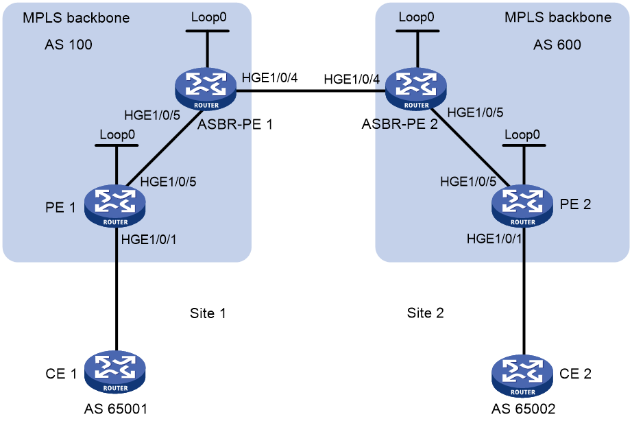
Table 2 Interface and IP address assignment
|
Interface |
IP address |
Device |
Interface |
IP address |
|
|
PE 1 |
Loop0 |
2.2.2.9/32 |
PE 2 |
Loop0 |
5.5.5.9/32 |
|
|
HGE1/0/1 |
30.0.0.1/8 |
|
HGE1/0/1 |
20.0.0.1/8 |
|
|
HGE1/0/5 |
1.1.1.2/8 |
|
HGE1/0/5 |
9.1.1.2/8 |
|
ASBR-PE 1 |
Loop0 |
3.3.3.9/32 |
ASBR-PE 2 |
Loop0 |
4.4.4.9/32 |
|
|
HGE1/0/5 |
1.1.1.1/8 |
|
HGE1/0/5 |
9.1.1.1/8 |
|
|
HGE1/0/4 |
11.0.0.2/8 |
|
HGE1/0/4 |
11.0.0.1/8 |
Prerequisites
By default, interfaces on the device are disabled (in ADM or Administratively Down state). To have an interface operate, you must use the undo shutdown command to enable that interface.
Procedure
1. Configure PE 1:
# Configure IS-IS on PE 1.
<PE1> system-view
[PE1] isis 1
[PE1-isis-1] network-entity 10.111.111.111.111.00
[PE1-isis-1] quit
# Configure LSR ID, and enable MPLS and LDP.
[PE1] mpls lsr-id 2.2.2.9
[PE1] mpls ldp
[PE1-ldp] quit
# Configure HundredGigE 1/0/5, and enable IS-IS, MPLS, and LDP on the interface.
[PE1] interface hundredgige 1/0/5
[PE1-HundredGigE1/0/5] ip address 1.1.1.2 255.0.0.0
[PE1-HundredGigE1/0/5] isis enable 1
[PE1-HundredGigE1/0/5] mpls enable
[PE1-HundredGigE1/0/5] mpls ldp enable
[PE1-HundredGigE1/0/5] quit
# Configure interface Loopback 0, and enable IS-IS on it.
[PE1] interface loopback 0
[PE1-LoopBack0] ip address 2.2.2.9 32
[PE1-LoopBack0] isis enable 1
[PE1-LoopBack0] quit
# Create VPN instance vpn1, and configure the RD and route target attributes.
[PE1] ip vpn-instance vpn1
[PE1-vpn-instance-vpn1] route-distinguisher 11:11
[PE1-vpn-instance-vpn1] vpn-target 1:1 2:2 3:3 import-extcommunity
[PE1-vpn-instance-vpn1] vpn-target 3:3 export-extcommunity
[PE1-vpn-instance-vpn1] quit
# Bind the interface connected to CE 1 to the created VPN instance.
[PE1] interface hundredgige 1/0/1
[PE1-HundredGigE1/0/1] ip binding vpn-instance vpn1
[PE1-HundredGigE1/0/1] ip address 30.0.0.1 8
[PE1-HundredGigE1/0/1] quit
# Enable BGP on PE 1.
[PE1] bgp 100
# Configure IBGP peer 3.3.3.9 as a VPNv4 peer.
[PE1-bgp-default] peer 3.3.3.9 as-number 100
[PE1-bgp-default] peer 3.3.3.9 connect-interface loopback 0
[PE1-bgp-default] address-family vpnv4
[PE1-bgp-default-vpnv4] peer 3.3.3.9 enable
[PE1-bgp-default-vpnv4] quit
# Redistribute direct routes to the routing table of VPN instance vpn1.
[PE1-bgp-default] ip vpn-instance vpn1
[PE1-bgp-default-vpn1] address-family ipv4 unicast
[PE1-bgp-default-ipv4-vpn1] import-route direct
[PE1-bgp-default-ipv4-vpn1] quit
[PE1-bgp-default-vpn1] quit
[PE1-bgp-default] quit
# Enable MPLS TE, RSVP-TE, and IS-IS TE. Configure MPLS TE attributes. Use RSVP-TE to establish MPLS TE tunnel 1. Set the tunnel destination address as the LSR ID of ASBR-PE 1 (3.3.3.9). Assign 2000 kbps bandwidth to the tunnel.
[PE1] mpls te
[PE1-te] quit
[PE1] rsvp
[PE1-rsvp] quit
[PE1] interface hundredgige 1/0/5
[PE1-HundredGigE1/0/5] mpls enable
[PE1-HundredGigE1/0/5] mpls te enable
[PE1-HundredGigE1/0/5] mpls te max-link-bandwidth 10000
[PE1-HundredGigE1/0/5] mpls te max-reservable-bandwidth 5000
[PE1-HundredGigE1/0/5] rsvp enable
[PE1-HundredGigE1/0/5] quit
[PE1] isis 1
[PE1-isis-1] cost-style wide
[PE1-isis-1] mpls te enable level-2
[PE1-isis-1] quit
[PE1] interface tunnel 1 mode mpls-te
[PE1-Tunnel1] ip address unnumbered interface LoopBack0
[PE1-Tunnel1] destination 3.3.3.9
[PE1-Tunnel1] mpls te signaling rsvp-te
[PE1-Tunnel1] mpls te bandwidth 2000
[PE1-Tunnel1] quit
# Create a tunnel policy named tpolicy1, and apply the tunnel policy to VPN instance vpn1.
[PE1] tunnel-policy tpolicy1
[PE1-tunnel-policy-tpolicy1] preferred-path tunnel 1
[PE1-tunnel-policy-tpolicy1] quit
[PE1] ip vpn-instance vpn1
[PE1-vpn-instance-vpn1] tnl-policy tpolicy1
[PE1-vpn-instance-vpn1] quit
2. Configure ASBR-PE 1:
# Configure IS-IS on ASBR-PE 1.
<ASBR-PE1> system-view
[ASBR-PE1] isis 1
[ASBR-PE1-isis-1] network-entity 10.222.222.222.222.00
[ASBR-PE1-isis-1] quit
# Configure LSR ID, and enable MPLS and LDP.
[ASBR-PE1] mpls lsr-id 3.3.3.9
[ASBR-PE1] mpls ldp
[ASBR-PE1-ldp] quit
# Configure HundredGigE 1/0/5, and enable IS-IS, MPLS, and LDP on the interface.
[ASBR-PE1] interface hundredgige 1/0/5
[ASBR-PE1-HundredGigE1/0/5] ip address 1.1.1.1 255.0.0.0
[ASBR-PE1-HundredGigE1/0/5] isis enable 1
[ASBR-PE1-HundredGigE1/0/5] mpls enable
[ASBR-PE1-HundredGigE1/0/5] mpls ldp enable
[ASBR-PE1-HundredGigE1/0/5] quit
# Configure HundredGigE 1/0/4, and enable MPLS on the interface.
[ASBR-PE1] interface hundredgige 1/0/4
[ASBR-PE1-HundredGigE1/0/4] ip address 11.0.0.2 255.0.0.0
[ASBR-PE1-HundredGigE1/0/4] mpls enable
[ASBR-PE1-HundredGigE1/0/4] quit
# Configure interface Loopback 0, and enable IS-IS on it.
[ASBR-PE1] interface loopback 0
[ASBR-PE1-LoopBack0] ip address 3.3.3.9 32
[ASBR-PE1-LoopBack0] isis enable 1
[ASBR-PE1-LoopBack0] quit
# Configure BGP on ASBR-PE 1.
[ASBR-PE1] bgp 100
[ASBR-PE1-bgp-default] peer 2.2.2.9 as-number 100
[ASBR-PE1-bgp-default] peer 2.2.2.9 connect-interface loopback 0
[ASBR-PE1-bgp-default] peer 11.0.0.1 as-number 600
[ASBR-PE1-bgp-default] peer 11.0.0.1 connect-interface hundredgige 1/0/4
# Disable route target based filtering of received VPNv4 routes.
[ASBR-PE1-bgp-default] address-family vpnv4
[ASBR-PE1-bgp-default-vpnv4] undo policy vpn-target
# Configure IBGP peer 2.2.2.9 and EBGP peer 11.0.0.1 as VPNv4 peers.
[ASBR-PE1-bgp-default-vpnv4] peer 11.0.0.1 enable
[ASBR-PE1-bgp-default-vpnv4] peer 2.2.2.9 enable
[ASBR-PE1-bgp-default-vpnv4] quit
[ASBR-PE1-bgp-default] quit
# Enable MPLS TE, RSVP-TE, and IS-IS TE. Configure MPLS TE attributes. Use RSVP-TE to establish MPLS TE tunnel 1. Set the tunnel destination address as the LSR ID of PE 1 (2.2.2.9). Assign 2000 kbps bandwidth to the tunnel.
[ASBR-PE1] mpls te
[ASBR-PE1-te] quit
[ASBR-PE1] rsvp
[ASBR-PE1-rsvp] quit
[ASBR-PE1] interface hundredgige 1/0/5
[ASBR-PE1-HundredGigE1/0/5] mpls enable
[ASBR-PE1-HundredGigE1/0/5] mpls te enable
[ASBR-PE1-HundredGigE1/0/5] mpls te max-link-bandwidth 10000
[ASBR-PE1-HundredGigE1/0/5] mpls te max-reservable-bandwidth 5000
[ASBR-PE1-HundredGigE1/0/5] rsvp enable
[ASBR-PE1-HundredGigE1/0/5] quit
[ASBR-PE1] isis 1
[ASBR-PE1-isis-1] cost-style wide
[ASBR-PE1-isis-1] mpls te enable level-2
[ASBR-PE1-isis-1] quit
[ASBR-PE1] interface tunnel 1 mode mpls-te
[ASBR-PE1-Tunnel1] ip address unnumbered interface LoopBack0
[ASBR-PE1-Tunnel1] destination 2.2.2.9
[ASBR-PE1-Tunnel1] mpls te signaling rsvp-te
[ASBR-PE1-Tunnel1] mpls te bandwidth 2000
[ASBR-PE1-Tunnel1] quit
# Configure tunnel policy tpolicy1 and tunnel selector ts1, specify the tunnel policy for the tunnel selector, and then apply the tunnel selector in BGP VPNv4 view.
[ASBR-PE1] tunnel-policy tpolicy1
[ASBR-PE1-tunnel-policy-tpolicy1] preferred-path tunnel 1
[ASBR-PE1-tunnel-policy-tpolicy1] quit
[ASBR-PE1] tunnel-selector ts1 permit node 1
[ASBR-PE1-tunnel-selector-ts1-1] apply tunnel-policy tpolicy1
[ASBR-PE1-tunnel-selector-ts1-1] quit
[ASBR-PE1] bgp 100
[ASBR-PE1-bgp-default] address-family vpnv4
[ASBR-PE1-bgp-default-vpnv4] apply tunnel-selector ts1
[ASBR-PE1-bgp-default-vpnv4] quit
[ASBR-PE1-bgp-default] quit
3. Configure ASBR-PE 2:
# Configure IS-IS on ASBR-PE 2.
<ASBR-PE2> system-view
[ASBR-PE2] isis 1
[ASBR-PE2-isis-1] network-entity 10.222.222.222.222.00
[ASBR-PE2-isis-1] quit
# Configure LSR ID, and enable MPLS and LDP.
[ASBR-PE2] mpls lsr-id 4.4.4.9
[ASBR-PE2] mpls ldp
[ASBR-PE2-ldp] quit
# Configure HundredGigE 1/0/5, and enable IS-IS, MPLS, and LDP on the interface.
[ASBR-PE2] interface hundredgige 1/0/5
[ASBR-PE2-HundredGigE1/0/5] ip address 9.1.1.1 255.0.0.0
[ASBR-PE2-HundredGigE1/0/5] isis enable 1
[ASBR-PE2-HundredGigE1/0/5] mpls enable
[ASBR-PE2-HundredGigE1/0/5] mpls ldp enable
[ASBR-PE2-HundredGigE1/0/5] quit
# Configure HundredGigE 1/0/4, and enable MPLS on the interface.
[ASBR-PE2] interface hundredgige 1/0/4
[ASBR-PE2-HundredGigE1/0/4] ip address 11.0.0.1 255.0.0.0
[ASBR-PE2-HundredGigE1/0/4] mpls enable
[ASBR-PE2-HundredGigE1/0/4] quit
# Configure interface Loopback 0, and enable IS-IS on it.
[ASBR-PE2] interface loopback 0
[ASBR-PE2-LoopBack0] ip address 4.4.4.9 32
[ASBR-PE2-LoopBack0] isis enable 1
[ASBR-PE2-LoopBack0] quit
# Configure BGP on ASBR-PE 2.
[ASBR-PE2] bgp 600
[ASBR-PE2-bgp-default] peer 11.0.0.2 as-number 100
[ASBR-PE2-bgp-default] peer 11.0.0.2 connect-interface hundredgige 1/0/4
[ASBR-PE2-bgp-default] peer 5.5.5.9 as-number 600
[ASBR-PE2-bgp-default] peer 5.5.5.9 connect-interface loopback 0
# Disable route target based filtering of received VPNv4 routes.
[ASBR-PE2-bgp-default] address-family vpnv4
[ASBR-PE2-bgp-default-vpnv4] undo policy vpn-target
# Configure IBGP peer 5.5.5.9 and EBGP peer 11.0.0.2 as VPNv4 peers.
[ASBR-PE2-bgp-default-vpnv4] peer 11.0.0.2 enable
[ASBR-PE2-bgp-default-vpnv4] peer 5.5.5.9 enable
[ASBR-PE2-bgp-default-vpnv4] quit
[ASBR-PE2-bgp-default] quit
# Enable MPLS TE, RSVP-TE, and IS-IS TE. Configure MPLS TE attributes. Use RSVP-TE to establish MPLS TE tunnel 1. Set the tunnel destination address as the LSR ID of PE 2 (5.5.5.9). Assign 2000 kbps bandwidth to the tunnel.
[ASBR-PE2] mpls te
[ASBR-PE2-te] quit
[ASBR-PE2] rsvp
[ASBR-PE2-rsvp] quit
[ASBR-PE2] interface hundredgige 1/0/5
[ASBR-PE2-HundredGigE1/0/5] mpls enable
[ASBR-PE2-HundredGigE1/0/5] mpls te enable
[ASBR-PE2-HundredGigE1/0/5] mpls te max-link-bandwidth 10000
[ASBR-PE2-HundredGigE1/0/5] mpls te max-reservable-bandwidth 5000
[ASBR-PE2-HundredGigE1/0/5] rsvp enable
[ASBR-PE2-HundredGigE1/0/5] quit
[ASBR-PE2] isis 1
[ASBR-PE2-isis-1] cost-style wide
[ASBR-PE2-isis-1] mpls te enable level-2
[ASBR-PE2-isis-1] quit
[ASBR-PE2] interface tunnel 1 mode mpls-te
[ASBR-PE2-Tunnel1] ip address unnumbered interface LoopBack0
[ASBR-PE2-Tunnel1] destination 5.5.5.9
[ASBR-PE2-Tunnel1] mpls te signaling rsvp-te
[ASBR-PE2-Tunnel1] mpls te bandwidth 2000
[ASBR-PE2-Tunnel1] quit
# Configure tunnel policy tpolicy1 and tunnel selector ts1, specify the tunnel policy for the tunnel selector, and then apply the tunnel selector in BGP VPNv4 view.
[ASBR-PE2] tunnel-policy tpolicy1
[ASBR-PE2-tunnel-policy-tpolicy1] preferred-path tunnel 1
[ASBR-PE2-tunnel-policy-tpolicy1] quit
[ASBR-PE2] tunnel-selector ts1 permit node 1
[ASBR-PE2-tunnel-selector-ts1-1] apply tunnel-policy tpolicy1
[ASBR-PE2-tunnel-selector-ts1-1] quit
[ASBR-PE2] bgp 600
[ASBR-PE2-bgp-default] address-family vpnv4
[ASBR-PE2-bgp-default-vpnv4] apply tunnel-selector ts1
[ASBR-PE2-bgp-default-vpnv4] quit
[ASBR-PE2-bgp-default] quit
4. Configure PE 2:
# Configure IS-IS on PE 2.
<PE2> system-view
[PE2] isis 1
[PE2-isis-1] network-entity 10.111.111.111.111.00
[PE2-isis-1] quit
# Configure LSR ID, and enable MPLS and LDP.
[PE2] mpls lsr-id 5.5.5.9
[PE2] mpls ldp
[PE2-ldp] quit
# Configure HundredGigE 1/0/5, and enable IS-IS, MPLS, and LDP on the interface.
[PE2] interface hundredgige 1/0/5
[PE2-HundredGigE1/0/5] ip address 9.1.1.2 255.0.0.0
[PE2-HundredGigE1/0/5] isis enable 1
[PE2-HundredGigE1/0/5] mpls enable
[PE2-HundredGigE1/0/5] mpls ldp enable
[PE2-HundredGigE1/0/5] quit
# Configure interface Loopback 0, and enable IS-IS on it.
[PE2] interface loopback 0
[PE2-LoopBack0] ip address 5.5.5.9 32
[PE2-LoopBack0] isis enable 1
[PE2-LoopBack0] quit
# Create VPN instance vpn1, and configure the RD and route target attributes.
[PE2] ip vpn-instance vpn1
[PE2-vpn-instance-vpn1] route-distinguisher 12:12
[PE2-vpn-instance-vpn1] vpn-target 1:1 2:2 3:3 import-extcommunity
[PE2-vpn-instance-vpn1] vpn-target 3:3 export-extcommunity
[PE2-vpn-instance-vpn1] quit
# Bind the interface connected to CE 2 to the created VPN instance.
[PE2] interface hundredgige 1/0/1
[PE2-HundredGigE1/0/1] ip binding vpn-instance vpn1
[PE2-HundredGigE1/0/1] ip address 20.0.0.1 8
[PE2-HundredGigE1/0/1] quit
# Enable BGP on PE 2.
[PE2] bgp 600
# Configure IBGP peer 4.4.4.9 as a VPNv4 peer.
[PE2-bgp-default] peer 4.4.4.9 as-number 600
[PE2-bgp-default] peer 4.4.4.9 connect-interface loopback 0
[PE2-bgp-default] address-family vpnv4
[PE2-bgp-default-vpnv4] peer 4.4.4.9 enable
[PE2-bgp-default-vpnv4] quit
# Redistribute direct routes to the routing table of VPN instance vpn1.
[PE2-bgp-default] ip vpn-instance vpn1
[PE2-bgp-default-vpn1] address-family ipv4 unicast
[PE2-bgp-default-ipv4-vpn1] import-route direct
[PE2-bgp-default-ipv4-vpn1] quit
[PE2-bgp-default-vpn1] quit
[PE2-bgp-default] quit
# Enable MPLS TE, RSVP-TE, and IS-IS TE. Configure MPLS TE attributes. Use RSVP-TE to establish MPLS TE tunnel 1. Set the tunnel destination address as the LSR ID of ASBR-PE 2 (4.4.4.9). Assign 2000 kbps bandwidth to the tunnel.
[PE2] mpls te
[PE2-te] quit
[PE2] rsvp
[PE2-rsvp] quit
[PE2] interface hundredgige 1/0/5
[PE2-HundredGigE1/0/5] mpls enable
[PE2-HundredGigE1/0/5] mpls te enable
[PE2-HundredGigE1/0/5] mpls te max-link-bandwidth 10000
[PE2-HundredGigE1/0/5] mpls te max-reservable-bandwidth 5000
[PE2-HundredGigE1/0/5] rsvp enable
[PE2-HundredGigE1/0/5] quit
[PE2] isis 1
[PE2-isis-1] cost-style wide
[PE2-isis-1] mpls te enable level-2
[PE2-isis-1] quit
[PE2] interface tunnel 1 mode mpls-te
[PE2-Tunnel1] ip address unnumbered interface LoopBack0
[PE2-Tunnel1] destination 4.4.4.9
[PE2-Tunnel1] mpls te signaling rsvp-te
[PE2-Tunnel1] mpls te bandwidth 2000
[PE2-Tunnel1] quit
# Create a tunnel policy named tpolicy1, and apply the tunnel policy to VPN instance vpn1.
[PE2] tunnel-policy tpolicy1
[PE2-tunnel-policy-tpolicy1] preferred-path tunnel 1
[PE2-tunnel-policy-tpolicy1] quit
[PE2] ip vpn-instance vpn1
[PE2-vpn-instance-vpn1] tnl-policy tpolicy1
[PE2-vpn-instance-vpn1] quit
Verifying the configuration
# Verify that the CE-facing interfaces (HundredGigE 1/0/1) on PE 1 and PE 2 can ping each other.
# Verify that tunnel policy tpolicy1 has been successfully applied between PE 1 and ASBR-PE 1 and between PE 2 and ASBR-PE 2. The devices select MPLS TE tunnel 1 as instructed by the tunnel policy.
Example: Configuring tunnel selectors for MPLS L3VPN inter-AS option C
Network configuration
As shown in Figure 3, site 1 and site 2 belong to the same VPN. CE 1 in site 1 accesses the MPLS network from PE 1 in AS 100. CE 2 in site 2 accesses the MPLS network from PE 2 in AS 600. OSPF is running within the ASs as the IGP.
PE 1 and ASBR-PE 1 exchange labeled IPv4 routes through IBGP. PE 2 and ASBR-PE 2 exchange labeled IPv4 routes through IBGP. ASBR-PE 1 and ASBR-PE 2 exchange VPNv4 routes through MP-EBGP. PE 1 and PE 2 are MP-EBGP peers and exchange VPNv4 routes.
On the PE and ASBR devices, enable SR-MPLS for OSPF and BGP. Configure the loopback interfaces to use dynamically allocated SIDs to establish SRLSPs. Create MPLS TE tunnels that use the SRLSPs to forward traffic.
On the PEs, apply a tunnel selector so they can select MPLS TE tunnels to forward traffic between the sites with guaranteed bandwidth.
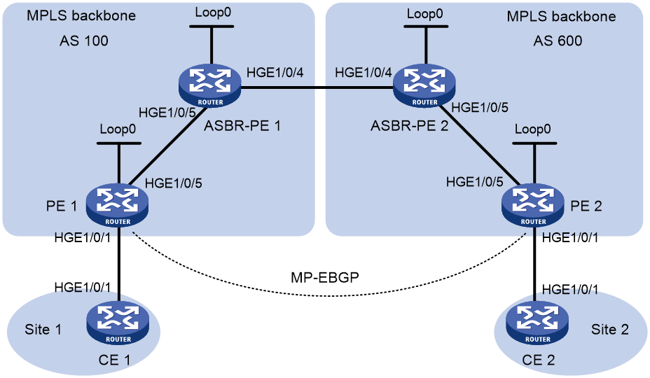
Table 3 Interface and IP address assignment
|
Device |
Interface |
IP address |
Device |
Inerface |
IP address |
|
PE 1 |
Loop0 |
2.2.2.9/32 |
PE 2 |
Loop0 |
5.5.5.9/32 |
|
|
HGE1/0/1 |
30.0.0.1/24 |
|
HGE1/0/1 |
20.0.0.1/24 |
|
|
HGE1/0/5 |
1.1.1.2/8 |
|
HGE1/0/5 |
9.1.1.2/8 |
|
ASBR-PE 1 |
Loop0 |
3.3.3.9/32 |
ASBR-PE 2 |
Loop0 |
4.4.4.9/32 |
|
|
HGE1/0/5 |
1.1.1.1/8 |
|
HGE1/0/5 |
9.1.1.1/8 |
|
|
HGE1/0/4 |
11.0.0.2/8 |
|
HGE1/0/4 |
11.0.0.1/8 |
|
CE 1 |
HGE1/0/1 |
30.0.0.2/24 |
CE 2 |
HGE1/0/1 |
20.0.0.2/24 |
Prerequisites
By default, interfaces on the device are disabled (in ADM or Administratively Down state). To have an interface operate, you must use the undo shutdown command to enable that interface.
Procedure
1. Configure CE 1:
# Configure an IP address for HundredGigE 1/0/1, and configure a static route.
<CE1> system-view
[CE1] interface hundredgige 1/0/1
[CE1-HundredGigE1/0/1] ip address 30.0.0.2 24
[CE1-HundredGigE1/0/1] quit
[CE1] ip route-static 100.0.0.0 24 30.0.0.1
# Establish an EBGP peer relationship with PE 1, and redistribute VPN routes.
[CE1] bgp 65001
[CE1-bgp-default] peer 30.0.0.1 as-number 100
[CE1-bgp-default] address-family ipv4 unicast
[CE1-bgp-default-ipv4] peer 30.0.0.1 enable
[CE1-bgp-default-ipv4] import-route direct
[CE1-bgp-default-ipv4] network 100.0.0.0 24
[CE1-bgp-default-ipv4] quit
[CE1-bgp-default] quit
2. Configure PE 1:
# Configure OSPF, configure the LSR ID, and enable MPLS and MPLS TE.
<PE1> system-view
[PE1] ospf 1 router-id 2.2.2.9
[PE1-ospf-1] quit
[PE1] interface hundredgige 1/0/5
[PE1-HundredGigE1/0/5] ospf 1 area 0
[PE1-HundredGigE1/0/5] mpls enable
[PE1-HundredGigE1/0/5] quit
[PE1] interface loopback 0
[PE1-LoopBack0] ip address 2.2.2.9 32
[PE1-LoopBack0] ospf 1 area 0
[PE1-LoopBack0] quit
[PE1] mpls lsr-id 2.2.2.9
[PE1] mpls te
[PE1-te] quit
# Enable SR-MPLS in OSPF view, and configure a prefix SID index.
[PE1] ospf 1
[PE1-ospf-1] segment-routing mpls
[PE1-ospf-1] quit
[PE1] interface loopback 0
[PE1-LoopBack0] ospf 1 prefix-sid index 20
[PE1-LoopBack0] quit
# Create VPN instance vpn1, and configure the RD and route target attributes.
[PE1] ip vpn-instance vpn1
[PE1-vpn-instance-vpn1] route-distinguisher 11:11
[PE1-vpn-instance-vpn1] vpn-target 1:1 2:2 3:3 import-extcommunity
[PE1-vpn-instance-vpn1] vpn-target 3:3 export-extcommunity
[PE1-vpn-instance-vpn1] quit
# Associate interface HundredGigE 1/0/1 with VPN instance vpn1, and specify the IP address for the interface.
[PE1] interface hundredgige 1/0/1
[PE1-HundredGigE1/0/1] ip binding vpn-instance vpn1
[PE1-HundredGigE1/0/1] ip address 30.0.0.1 24
[PE1-HundredGigE1/0/1] quit
# Create a routing policy named policy1. Configure a label index for the matching routes.
[PE1] route-policy policy1 permit node 1
[PE1-route-policy-policy1-1] apply label-index 20
[PE1-route-policy-policy1-1] quit
# Enable BGP to exchange labeled IPv4 routes with IBGP peer 3.3.3.9.
[PE1] bgp 100
[PE1-bgp-default] peer 3.3.3.9 as-number 100
[PE1-bgp-default] peer 3.3.3.9 connect-interface loopback 0
[PE1-bgp-default] address-family ipv4 unicast
[PE1-bgp-default-ipv4] peer 3.3.3.9 enable
[PE1-bgp-default-ipv4] peer 3.3.3.9 label-route-capability
# Enable SR-MPLS for BGP.
[PE1-bgp-default-ipv4] segment-routing mpls
# Inject the IP address of Loopback 0 to the BGP routing table, and apply routing policy policy1.
[PE1-bgp-default-ipv4] network 2.2.2.9 32 route-policy policy1
[PE1-bgp-default-ipv4] quit
# Enable BGP to establish an EBGP session to indirectly connected peer 5.5.5.9, and set the maximum hop count to 10.
[PE1-bgp-default] peer 5.5.5.9 as-number 600
[PE1-bgp-default] peer 5.5.5.9 connect-interface loopback 0
[PE1-bgp-default] peer 5.5.5.9 ebgp-max-hop 10
# Configure peer 5.5.5.9 as a VPNv4 peer.
[PE1-bgp-default] address-family vpnv4
[PE1-bgp-default-vpnv4] peer 5.5.5.9 enable
[PE1-bgp-default-vpnv4] quit
# Establish an EBGP peer relationship with CE 1, and add the learned BGP routes to the routing table of VPN instance vpn1.
[PE1-bgp-default] ip vpn-instance vpn1
[PE1-bgp-default-vpn1] peer 30.0.0.2 as-number 65001
[PE1-bgp-default-vpn1] address-family ipv4 unicast
[PE1-bgp-default-ipv4-vpn1] peer 30.0.0.2 enable
[PE1-bgp-default-ipv4-vpn1] quit
[PE1-bgp-default-vpn1] quit
[PE1-bgp-default] quit
# Configure static SRLSPs. The outgoing labels are 16030 and 16050, which are the prefix SIDs assigned to PE 1 by ASBR-PE 1 and PE 2, respectively.
[PE1] static-sr-mpls lsp static-sr-lsp-1 out-label 16030 16050
[PE1] static-sr-mpls lsp static-sr-lsp-2 out-label 16030 16050
# Establish MPLS tunnels Tunnel 1 and Tunnel 2 to PE 2. Configure the tunnel destination address as 5.5.5.9, the IP address of the loopback interface on PE 2. Configure the tunnels to use static SRLSPs.
[PE1] interface tunnel 1 mode mpls-te
[PE1-Tunnel1] ip address unnumbered interface LoopBack0
[PE1-Tunnel1] destination 5.5.5.9
[PE1-Tunnel1] mpls te signaling static
[PE1-Tunnel1] mpls te static-sr-mpls static-sr-lsp-1
[PE1-Tunnel1] quit
[PE1] interface tunnel 2 mode mpls-te
[PE1-Tunnel2] ip address unnumbered interface LoopBack0
[PE1-Tunnel2] destination 5.5.5.9
[PE1-Tunnel2] mpls te signaling static
[PE1-Tunnel2] mpls te static-sr-mpls static-sr-lsp-2
[PE1-Tunnel2] quit
# Configure IP prefix lists p1 and p2. Create tunnel policies tp1 and tp2. Create tunnel selector ts1. Apply the tunnel selector in BGP VPNv4 view.
[PE1] ip prefix-list p1 permit 20.0.0.0 24
[PE1] ip prefix-list p2 permit 200.0.0.0 24
[PE1] tunnel-policy tp1
[PE1-tunnel-policy-tp1] preferred-path tunnel 1
[PE1-tunnel-policy-tp1] quit
[PE1] tunnel-policy tp2
[PE1-tunnel-policy-tp2] preferred-path tunnel 2
[PE1-tunnel-policy-tp2] quit
[PE1] tunnel-selector ts1 permit node 1
[PE1-tunnel-selector-ts1-1] if-match ip address prefix-list p1
[PE1-tunnel-selector-ts1-1] apply tunnel-policy tp1
[PE1-tunnel-selector-ts1-1] quit
[PE1] tunnel-selector ts1 permit node 2
[PE1-tunnel-selector-ts1-2] if-match ip address prefix-list p2
[PE1-tunnel-selector-ts1-2] apply tunnel-policy tp2
[PE1-tunnel-selector-ts1-2] quit
[PE1] bgp 100
[PE1-bgp-default] address-family vpnv4
[PE1-bgp-default-vpnv4] apply tunnel-selector ts1
3. Configure ASBR-PE 1:
# Configure OSPF, configure the LSR ID, and enable MPLS and MPLS TE.
<ASBR-PE1> system-view
[ASBR-PE1] ospf 1 router-id 3.3.3.9
[ASBR-PE1-ospf-1] quit
[ASBR-PE1] interface hundredgige 1/0/4
[ASBR-PE1-HundredGigE1/0/4] mpls enable
[ASBR-PE1-HundredGigE1/0/4] quit
[ASBR-PE1] interface hundredgige 1/0/5
[ASBR-PE1-HundredGigE1/0/5] ospf 1 area 0
[ASBR-PE1-HundredGigE1/0/5] mpls enable
[ASBR-PE1-HundredGigE1/0/5] quit
[ASBR-PE1] interface loopback 0
[ASBR-PE1-LoopBack0] ip address 3.3.3.9 32
[ASBR-PE1-LoopBack0] ospf 1 area 0
[ASBR-PE1-LoopBack0] quit
[ASBR-PE1] mpls lsr-id 3.3.3.9
[ASBR-PE1] mpls te
[ASBR-PE1-te] quit
# Enable SR-MPLS in OSPF view, and configure a prefix SID index.
[ASBR-PE1] ospf 1
[ASBR-PE1-ospf-1] segment-routing mpls
[ASBR-PE1-ospf-1] quit
[ASBR-PE1] interface loopback 0
[ASBR-PE1-LoopBack0] ospf 1 prefix-sid index 30
[ASBR-PE1-LoopBack0] quit
# Enable BGP to exchange labeled IPv4 routes with IBGP peer 2.2.2.9.
[ASBR-PE1] bgp 100
[ASBR-PE1-bgp-default] peer 2.2.2.9 as-number 100
[ASBR-PE1-bgp-default] peer 2.2.2.9 connect-interface loopback 0
[ASBR-PE1-bgp-default] address-family ipv4 unicast
[ASBR-PE1-bgp-default-ipv4] peer 2.2.2.9 enable
[ASBR-PE1-bgp-default-ipv4] peer 2.2.2.9 label-route-capability
# Enable SR-MPLS for BGP.
[ASBR-PE1-bgp-default-ipv4] segment-routing mpls
[ASBR-PE1-bgp-default-ipv4] quit
# Enable BGP to exchange labeled IPv4 routes with EBGP peer 11.0.0.1.
[ASBR-PE1-bgp-default] peer 11.0.0.1 as-number 600
[ASBR-PE1-bgp-default] address-family ipv4 unicast
[ASBR-PE1-bgp-default-ipv4] peer 11.0.0.1 enable
[ASBR-PE1-bgp-default-ipv4] peer 11.0.0.1 label-route-capability
[ASBR-PE1-bgp-default-ipv4] quit
[ASBR-PE1-bgp-default] quit
4. Configure ASBR-PE 2:
# Configure OSPF, configure the LSR ID, and enable MPLS and MPLS TE.
<ASBR-PE2> system-view
[ASBR-PE2] ospf 1 router-id 4.4.4.9
[ASBR-PE2-ospf-1] quit
[ASBR-PE2] interface hundredgige 1/0/4
[ASBR-PE2-HundredGigE1/0/4] mpls enable
[ASBR-PE2-HundredGigE1/0/4] quit
[ASBR-PE2] interface hundredgige 1/0/5
[ASBR-PE2-HundredGigE1/0/5] ospf 1 area 0
[ASBR-PE2-HundredGigE1/0/5] mpls enable
[ASBR-PE1-HundredGigE1/0/5] quit
[ASBR-PE2] interface loopback 0
[ASBR-PE2-LoopBack0] ip address 4.4.4.9 32
[ASBR-PE2-LoopBack0] ospf 1 area 0
[ASBR-PE2-LoopBack0] quit
[ASBR-PE2] mpls lsr-id 4.4.4.9
[ASBR-PE2] mpls te
# Enable SR-MPLS in OSPF view, and configure a prefix SID index.
[ASBR-PE2] ospf 1
[ASBR-PE2-ospf-1] segment-routing mpls
[ASBR-PE2-ospf-1] quit
[ASBR-PE2] interface loopback 0
[ASBR-PE2-LoopBack0] ospf 1 prefix-sid index 40
[ASBR-PE2-LoopBack0] quit
# Enable BGP to exchange labeled IPv4 routes with EBGP peer 5.5.5.9.
[ASBR-PE2] bgp 600
[ASBR-PE2-bgp-default] peer 5.5.5.9 as-number 600
[ASBR-PE2-bgp-default] peer 5.5.5.9 connect-interface loopback 0
[ASBR-PE2-bgp-default] address-family ipv4 unicast
[ASBR-PE2-bgp-default-ipv4] peer 5.5.5.9 enable
[ASBR-PE2-bgp-default-ipv4] peer 5.5.5.9 label-route-capability
# Enable SR-MPLS for BGP.
[ASBR-PE2-bgp-default-ipv4] segment-routing mpls
[ASBR-PE2-bgp-default-ipv4] quit
# Enable BGP to exchange labeled IPv4 routes with EBGP peer 11.0.0.2.
[ASBR-PE2-bgp-default] peer 11.0.0.2 as-number 100
[ASBR-PE2-bgp-default] address-family ipv4 unicast
[ASBR-PE2-bgp-default-ipv4] peer 11.0.0.2 enable
[ASBR-PE2-bgp-default-ipv4] peer 11.0.0.2 label-route-capability
[ASBR-PE2-bgp-default-ipv4] quit
[ASBR-PE2-bgp-default] quit
5. Configure PE 2:
# Configure IS-IS, configure the MPLS LSR ID, and enable MPLS and LDP.
<PE2> system-view
[PE2] ospf 1 router-id 5.5.5.9
[PE2-ospf-1] quit
[PE2] interface hundredgige 1/0/5
[PE2-HundredGigE1/0/5] ospf 1 area 0
[PE2-HundredGigE1/0/5] mpls enable
[PE2-HundredGigE1/0/5] quit
[PE2] interface loopback 0
[PE2-LoopBack0] ip address 5.5.5.9 32
[PE2-LoopBack0] ospf 1 area 0
[PE2-LoopBack0] quit
[PE2] mpls lsr-id 5.5.5.9
[PE2] mpls te
[PE2-te] quit
# Enable SR-MPLS in OSPF view, and configure a prefix SID index.
[PE2] ospf 1
[PE2-ospf-1] segment-routing mpls
[PE2] interface loopback 0
[PE2-LoopBack0] ospf 1 prefix-sid index 50
[PE2-LoopBack0] quit
# Create VPN instance vpn1, and configure the RD and route target attributes.
[PE2] ip vpn-instance vpn1
[PE2-vpn-instance-vpn1] route-distinguisher 11:11
[PE2-vpn-instance-vpn1] vpn-target 1:1 2:2 3:3 import-extcommunity
[PE2-vpn-instance-vpn1] vpn-target 3:3 export-extcommunity
[PE2-vpn-instance-vpn1] quit
# Associate interface HundredGigE 1/0/1 with VPN instance vpn1, and specify the IP address for the interface.
[PE2] interface hundredgige 1/0/1
[PE2-HundredGigE1/0/1] ip binding vpn-instance vpn1
[PE2-HundredGigE1/0/1] ip address 20.0.0.1 24
[PE2-HundredGigE1/0/1] quit
# Create a routing policy named policy1. Configure a label index for the matching routes.
[PE2] route-policy policy1 permit node 1
[PE2-route-policy-policy1-1] apply label-index 50
[PE2-route-policy-policy1-1] quit
# Enable BGP to exchange labeled IPv4 routes with IBGP peer 4.4.4.9.
[PE2] bgp 600
[PE2-bgp-default] peer 4.4.4.9 as-number 100
[PE2-bgp-default] peer 4.4.4.9 connect-interface loopback 0
[PE2-bgp-default] address-family ipv4 unicast
[PE2-bgp-default-ipv4] peer 4.4.4.9 enable
[PE2-bgp-default-ipv4] peer 4.4.4.9 label-route-capability
# Enable SR-MPLS for BGP.
[PE2-bgp-default-ipv4] segment-routing mpls
# Inject the IP address of Loopback 0 to the BGP routing table, and apply routing policy policy1.
[PE2-bgp-default-ipv4] network 5.5.5.9 32 route-policy policy1
[PE2-bgp-default-ipv4] quit
# Enable BGP to establish an EBGP session to indirectly connected peer 2.2.2.9, and set the maximum hop count to 10.
[PE2-bgp-default] peer 2.2.2.9 as-number 600
[PE2-bgp-default] peer 2.2.2.9 connect-interface loopback 0
[PE2-bgp-default] peer 2.2.2.9 ebgp-max-hop 10
# Configure peer 2.2.2.9 as a VPNv4 peer.
[PE2-bgp-default] address-family vpnv4
[PE2-bgp-default-vpnv4] peer 2.2.2.9 enable
[PE2-bgp-default-vpnv4] quit
# Establish an EBGP peer relationship with CE 2, and add the learned BGP routes to the routing table of VPN instance vpn1.
[PE2-bgp-default] ip vpn-instance vpn1
[PE2-bgp-default-vpn1] peer 20.0.0.2 as-number 65001
[PE2-bgp-default-vpn1] address-family ipv4 unicast
[PE2-bgp-default-ipv4-vpn1] peer 20.0.0.2 enable
[PE2-bgp-default-ipv4-vpn1] quit
[PE2-bgp-default-vpn1] quit
[PE2-bgp-default] quit
# Configure static SRLSPs. The outgoing labels are 16040 and 16020, which are the prefix SIDs assigned to PE 2 by ASBR-PE 2 and PE 1, respectively.
[PE2] static-sr-mpls lsp static-sr-lsp-1 out-label 16040 16020
[PE2] static-sr-mpls lsp static-sr-lsp-2 out-label 16040 16020
# Establish MPLS tunnels Tunnel 1 and Tunnel 2 to PE 1. Configure the tunnel destination address as 2.2.2.9, the IP address of the loopback interface on PE 1. Configure the tunnels to use static SRLSPs.
[PE2] interface tunnel 1 mode mpls-te
[PE2-Tunnel1] ip address unnumbered interface LoopBack0
[PE2-Tunnel1] destination 2.2.2.9
[PE2-Tunnel1] mpls te signaling static
[PE2-Tunnel1] mpls te static-sr-mpls static-sr-lsp-1
[PE2-Tunnel1] quit
[PE2] interface tunnel 2 mode mpls-te
[PE2-Tunnel2] ip address unnumbered interface LoopBack0
[PE2-Tunnel2] destination 2.2.2.9
[PE2-Tunnel2] mpls te signaling static
[PE2-Tunnel2] mpls te static-sr-mpls static-sr-lsp-2
[PE2-Tunnel2] quit
# Configure IP prefix lists p1 and p2. Create tunnel policies tp1 and tp2. Create tunnel selector ts1. Apply the tunnel selector in BGP VPNv4 view.
[PE2] ip prefix-list p1 permit 30.0.0.0 24
[PE2] ip prefix-list p2 permit 100.0.0.0 24
[PE2] tunnel-policy tp1
[PE2-tunnel-policy-tp1] preferred-path tunnel 1
[PE2-tunnel-policy-tp1] quit
[PE2] tunnel-policy tp2
[PE2-tunnel-policy-tp2] preferred-path tunnel 2
[PE2-tunnel-policy-tp2] quit
[PE2] tunnel-selector ts1 permit node 1
[PE2-tunnel-selector-ts1-1] if-match ip address prefix-list p1
[PE2-tunnel-selector-ts1-1] apply tunnel-policy tp1
[PE2-tunnel-selector-ts1-1] quit
[PE2] tunnel-selector ts1 permit node 2
[PE2-tunnel-selector-ts1-2] if-match ip address prefix-list p2
[PE2-tunnel-selector-ts1-2] apply tunnel-policy tp2
[PE2-tunnel-selector-ts1-2] quit
[PE2] bgp 600
[PE2-bgp-default] address-family vpnv4
[PE2-bgp-default-vpnv4] apply tunnel-selector ts1
6. Configure CE 2:
# Configure an IP address for HundredGigE 1/0/1, and configure a static route.
<CE2> system-view
[CE2] interface hundredgige 1/0/1
[CE2-HundredGigE1/0/1] ip address 20.0.0.2 24
[CE2-HundredGigE1/0/1] quit
[CE2] ip route-static 200.0.0.0 24 20.0.0.1
# Establish an EBGP peer relationship with PE 2, and redistribute VPN routes.
[CE2] bgp 65002
[CE2-bgp-default] peer 20.0.0.1 as-number 600
[CE2-bgp-default] address-family ipv4 unicast
[CE2-bgp-default-ipv4] peer 20.0.0.1 enable
[CE2-bgp-default-ipv4] import-route direct
[CE2-bgp-default-ipv4] network 200.0.0.0 24
[CE2-bgp-default-ipv4] quit
[CE2-bgp-default] quit
Verifying the configuration
# Use the display ip routing-table command to verify that CE 1 and CE 2 have a route to reach each other.
# Verify that CE 1 and CE 2 can ping each other.
Example: Configuring tunnel selectors for HoVPN
Network configuration
As shown in Figure 4, the MPLS VPN network is a two-level HoVPN. The PE devices on the level 1 network are SPEs. The PE devices on the level 2 network are UPEs.
The SPEs provide access service for the UPEs. The UPEs provide access service for the end users of the VPNs.
Configure routing policies on the SPEs to filter routes to be advertised to the UPEs. So, CE 1 and CE 3 in VPN 1 can communicate with each other, but CE 2 and CE 4 in VPN 2 cannot communicate with each other.
Apply a tunnel selector on the SPEs and UPEs, so the VPN traffic can be forwarded by MPLS TE tunnels with guaranteed bandwidth.
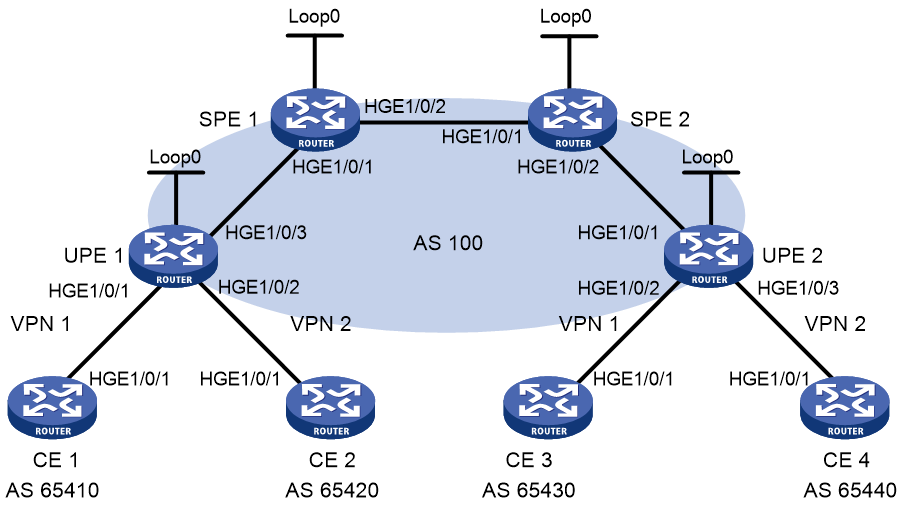
Table 4 Interface and IP address assignment
|
Device |
Interface |
IP address |
Device |
Interface |
IP address |
|
CE 1 |
HGE1/0/1 |
10.2.1.1/24 |
CE 3 |
HGE1/0/1 |
10.1.1.1/24 |
|
CE 2 |
HGE1/0/1 |
10.4.1.1/24 |
CE 4 |
HGE1/0/1 |
10.3.1.1/24 |
|
UPE 1 |
Loop0 |
1.1.1.9/32 |
UPE 2 |
Loop0 |
4.4.4.9/32 |
|
|
HGE1/0/1 |
10.2.1.2/24 |
|
HGE1/0/1 |
172.2.1.1/24 |
|
|
HGE1/0/2 |
10.4.1.2/24 |
|
HGE1/0/2 |
10.1.1.2/24 |
|
|
HGE1/0/3 |
172.1.1.1/24 |
|
HGE1/0/3 |
10.3.1.2/24 |
|
SPE 1 |
Loop0 |
2.2.2.9/32 |
SPE 2 |
Loop0 |
3.3.3.9/32 |
|
|
HGE1/0/1 |
172.1.1.2/24 |
|
HGE1/0/1 |
180.1.1.2/24 |
|
|
HGE1/0/2 |
180.1.1.1/24 |
|
HGE1/0/2 |
172.2.1.2/24 |
Prerequisites
By default, interfaces on the device are disabled (in ADM or Administratively Down state). To have an interface operate, you must use the undo shutdown command to enable that interface.
Procedure
1. Configure UPE 1:
# Configure basic MPLS and MPLS LDP to establish LDP LSPs.
<UPE1> system-view
[UPE1] interface loopback 0
[UPE1-LoopBack0] ip address 1.1.1.9 32
[UPE1-LoopBack0] quit
[UPE1] mpls lsr-id 1.1.1.9
[UPE1] mpls ldp
[UPE1-ldp] quit
[UPE1] interface hundredgige 1/0/3
[UPE1-HundredGigE1/0/3] ip address 172.1.1.1 24
[UPE1-HundredGigE1/0/3] mpls enable
[UPE1-HundredGigE1/0/3] mpls ldp enable
[UPE1-HundredGigE1/0/3] quit
# Configure the IGP (OSPF in this example).
[UPE1] ospf
[UPE1-ospf-1] area 0
[UPE1-ospf-1-area-0.0.0.0] network 172.1.1.0 0.0.0.255
[UPE1-ospf-1-area-0.0.0.0] network 1.1.1.9 0.0.0.0
[UPE1-ospf-1-area-0.0.0.0] quit
[UPE1-ospf-1] quit
# Configure VPN instances vpn1 and vpn2, allowing CE 1 and CE 2 to access UPE 1.
[UPE1] ip vpn-instance vpn1
[UPE1-vpn-instance-vpn1] route-distinguisher 100:1
[UPE1-vpn-instance-vpn1] vpn-target 100:1 both
[UPE1-vpn-instance-vpn1] quit
[UPE1] ip vpn-instance vpn2
[UPE1-vpn-instance-vpn2] route-distinguisher 100:2
[UPE1-vpn-instance-vpn2] vpn-target 100:2 both
[UPE1-vpn-instance-vpn2] quit
[UPE1] interface hundredgige 1/0/1
[UPE1-HundredGigE1/0/1] ip binding vpn-instance vpn1
[UPE1-HundredGigE1/0/1] ip address 10.2.1.2 24
[UPE1-HundredGigE1/0/1] quit
[UPE1] interface hundredgige 1/0/2
[UPE1-HundredGigE1/0/2] ip binding vpn-instance vpn2
[UPE1-HundredGigE1/0/2] ip address 10.4.1.2 24
[UPE1-HundredGigE1/0/2] quit
# Establish an MP-IBGP peer relationship with SPE 1.
[UPE1] bgp 100
[UPE1-bgp-default] peer 2.2.2.9 as-number 100
[UPE1-bgp-default] peer 2.2.2.9 connect-interface loopback 0
[UPE1-bgp-default] address-family vpnv4
[UPE1-bgp-default-vpnv4] peer 2.2.2.9 enable
[UPE1-bgp-default-vpnv4] quit
# Establish an EBGP peer relationship with CE 1.
[UPE1-bgp-default] ip vpn-instance vpn1
[UPE1-bgp-default-vpn1] peer 10.2.1.1 as-number 65410
[UPE1-bgp-default-vpn1] address-family ipv4 unicast
[UPE1-bgp-default-ipv4-vpn1] peer 10.2.1.1 enable
[UPE1-bgp-default-ipv4-vpn1] quit
[UPE1-bgp-default-vpn1] quit
# Establish an EBGP peer relationship with CE 2.
[UPE1-bgp-default] ip vpn-instance vpn2
[UPE1-bgp-default-vpn2] peer 10.4.1.1 as-number 65420
[UPE1-bgp-default-vpn2] address-family ipv4 unicast
[UPE1-bgp-default-ipv4-vpn2] peer 10.4.1.1 enable
[UPE1-bgp-default-ipv4-vpn2] quit
[UPE1-bgp-default-vpn2] quit
[UPE1-bgp-default] quit
# Enable MPLS TE, RSVP-TE, and OSPF TE. Configure MPLS TE attributes. Use RSVP-TE to establish MPLS TE tunnels (Tunnel 1 and Tunnel 2). Set the tunnels' destination address as the LSR ID of SPE 1 (2.2.2.9). Assign 2000 kbps bandwidth to the tunnels.
[UPE1] mpls te
[UPE1-te] quit
[UPE1] rsvp
[UPE1-rsvp] quit
[UPE1] interface hundredgige 1/0/3
[UPE1-HundredGigE1/0/3] mpls enable
[UPE1-HundredGigE1/0/3] mpls te enable
[UPE1-HundredGigE1/0/3] mpls te max-link-bandwidth 10000
[UPE1-HundredGigE1/0/3] mpls te max-reservable-bandwidth 5000
[UPE1-HundredGigE1/0/3] rsvp enable
[UPE1-HundredGigE1/0/3] quit
[UPE1] ospf 1
[UPE1-ospf-1] area 0
[UPE1-ospf-1-area-0.0.0.0] mpls te enable
[UPE1-ospf-1] quit
[UPE1] interface tunnel 1 mode mpls-te
[UPE1-Tunnel1] ip address unnumbered interface LoopBack0
[UPE1-Tunnel1] destination 2.2.2.9
[UPE1-Tunnel1] mpls te signaling rsvp-te
[UPE1-Tunnel1] mpls te bandwidth 2000
[UPE1-Tunnel1] quit
[UPE1] interface tunnel 2 mode mpls-te
[UPE1-Tunnel2] ip address unnumbered interface LoopBack0
[UPE1-Tunnel2] destination 2.2.2.9
[UPE1-Tunnel2] mpls te signaling rsvp-te
[UPE1-Tunnel2] mpls te bandwidth 2000
[UPE1-Tunnel2] quit
# Create a tunnel policy named tpolicy1, and apply the tunnel policy to VPN instance vpn1.
[UPE1] tunnel-policy tpolicy1
[UPE1-tunnel-policy-tpolicy1] select-seq cr-lsp lsp load-balance-number 2
[UPE1-tunnel-policy-tpolicy1] quit
[UPE1] ip vpn-instance vpn1
[UPE1-vpn-instance-vpn1] tnl-policy tpolicy1
[UPE1-vpn-instance-vpn1] quit
2. Configure CE 1:
<CE1> system-view
[CE1] interface hundredgige 1/0/1
[CE1-HundredGigE1/0/1] ip address 10.2.1.1 255.255.255.0
[CE1-HundredGigE1/0/1] quit
[CE1] bgp 65410
[CE1-bgp-default] peer 10.2.1.2 as-number 100
[CE1-bgp-default] address-family ipv4 unicast
[CE1-bgp-default-ipv4] peer 10.2.1.2 enable
[CE1-bgp-default-ipv4] import-route direct
[CE1-bgp-default-ipv4] quit
[CE1-bgp-default] quit
3. Configure CE 2:
<CE2> system-view
[CE2] interface hundredgige 1/0/1
[CE2-HundredGigE1/0/1] ip address 10.4.1.1 255.255.255.0
[CE2-HundredGigE1/0/1] quit
[CE2] bgp 65420
[CE2-bgp-default] peer 10.4.1.2 as-number 100
[CE2-bgp-default] address-family ipv4 unicast
[CE2-bgp-default-ipv4] peer 10.4.1.2 enable
[CE2-bgp-default-ipv4] import-route direct
[CE2-bgp-default-ipv4] quit
[CE2-bgp-default] quit
4. Configure UPE 2:
# Configure basic MPLS and MPLS LDP to establish LDP LSPs.
<UPE2> system-view
[UPE2] interface loopback 0
[UPE2-LoopBack0] ip address 4.4.4.9 32
[UPE2-LoopBack0] quit
[UPE2] mpls lsr-id 4.4.4.9
[UPE2] mpls ldp
[UPE2-ldp] quit
[UPE2] interface hundredgige 1/0/1
[UPE2-HundredGigE1/0/1] ip address 172.2.1.1 24
[UPE2-HundredGigE1/0/1] mpls enable
[UPE2-HundredGigE1/0/1] mpls ldp enable
[UPE2-HundredGigE1/0/1] quit
# Configure the IGP (OSPF in this example).
[UPE2] ospf
[UPE2-ospf-1] area 0
[UPE2-ospf-1-area-0.0.0.0] network 172.2.1.0 0.0.0.255
[UPE2-ospf-1-area-0.0.0.0] network 4.4.4.9 0.0.0.0
[UPE2-ospf-1-area-0.0.0.0] quit
[UPE2-ospf-1] quit
# Configure VPN instances vpn1 and vpn2, allowing CE 3 and CE 4 to access UPE 2.
[UPE2] ip vpn-instance vpn1
[UPE2-vpn-instance-vpn1] route-distinguisher 300:1
[UPE2-vpn-instance-vpn1] vpn-target 100:1 both
[UPE2-vpn-instance-vpn1] quit
[UPE2] ip vpn-instance vpn2
[UPE2-vpn-instance-vpn2] route-distinguisher 400:2
[UPE2-vpn-instance-vpn2] vpn-target 100:2 both
[UPE2-vpn-instance-vpn2] quit
[UPE2] interface hundredgige 1/0/2
[UPE2-HundredGigE1/0/2] ip binding vpn-instance vpn1
[UPE2-HundredGigE1/0/2] ip address 10.1.1.2 24
[UPE2-HundredGigE1/0/2] quit
[UPE2] interface hundredgige 1/0/3
[UPE2-HundredGigE1/0/3] ip binding vpn-instance vpn2
[UPE2-HundredGigE1/0/3] ip address 10.3.1.2 24
[UPE2-HundredGigE1/0/3] quit
# Establish an MP-IBGP peer relationship with SPE 2.
[UPE2] bgp 100
[UPE2-bgp-default] peer 3.3.3.9 as-number 100
[UPE2-bgp-default] peer 3.3.3.9 connect-interface loopback 0
[UPE2-bgp-default] address-family vpnv4
[UPE2-bgp-default-vpnv4] peer 3.3.3.9 enable
[UPE2-bgp-default-vpnv4] quit
# Establish an EBGP peer relationship with CE 3.
[UPE2-bgp-default] ip vpn-instance vpn1
[UPE2-bgp-default-vpn1] peer 10.1.1.1 as-number 65430
[UPE2-bgp-default-vpn1] address-family ipv4 unicast
[UPE2-bgp-default-ipv4-vpn1] peer 10.1.1.1 enable
[UPE2-bgp-default-ipv4-vpn1] quit
[UPE2-bgp-default-vpn1] quit
# Establish an EBGP peer relationship with CE 4.
[UPE2-bgp-default] ip vpn-instance vpn2
[UPE2-bgp-default-vpn2] peer 10.3.1.1 as-number 65440
[UPE2-bgp-default-vpn2] address-family ipv4 unicast
[UPE2-bgp-default-ipv4-vpn2] peer 10.3.1.1 enable
[UPE2-bgp-default-ipv4-vpn2] quit
[UPE2-bgp-default-vpn2] quit
[UPE2-bgp-default] quit
# Enable MPLS TE, RSVP-TE, and OSPF TE. Configure MPLS TE attributes. Use RSVP-TE to establish MPLS TE tunnels (Tunnel 1 and Tunnel 2). Set the tunnels' destination address as the LSR ID of SPE 2 (3.3.3.9). Assign 2000 kbps bandwidth to the tunnels.
[UPE2] mpls te
[UPE2-te] quit
[UPE2] rsvp
[UPE2-rsvp] quit
[UPE2] interface hundredgige 1/0/3
[UPE2-HundredGigE1/0/3] mpls enable
[UPE2-HundredGigE1/0/3] mpls te enable
[UPE2-HundredGigE1/0/3] mpls te max-link-bandwidth 10000
[UPE2-HundredGigE1/0/3] mpls te max-reservable-bandwidth 5000
[UPE2-HundredGigE1/0/3] rsvp enable
[UPE2-HundredGigE1/0/3] quit
[UPE2] ospf 1
[UPE2-ospf-1] area 0
[UPE2-ospf-1-area-0.0.0.0] mpls te enable
[UPE2-ospf-1] quit
[UPE2] interface tunnel 1 mode mpls-te
[UPE2-Tunnel1] ip address unnumbered interface LoopBack0
[UPE2-Tunnel1] destination 3.3.3.9
[UPE2-Tunnel1] mpls te signaling rsvp-te
[UPE2-Tunnel1] mpls te bandwidth 2000
[UPE2-Tunnel1] quit
[UPE2] interface tunnel 2 mode mpls-te
[UPE2-Tunnel2] ip address unnumbered interface LoopBack0
[UPE2-Tunnel2] destination 3.3.3.9
[UPE2-Tunnel2] mpls te signaling rsvp-te
[UPE2-Tunnel2] mpls te bandwidth 2000
[UPE2-Tunnel2] quit
# Create a tunnel policy named tpolicy1, and apply the tunnel policy to VPN instance vpn1.
[UPE2] tunnel-policy tpolicy1
[UPE2-tunnel-policy-tpolicy1] select-seq cr-lsp lsp load-balance-number 2
[UPE2-tunnel-policy-tpolicy1] quit
[UPE2] ip vpn-instance vpn1
[UPE2-vpn-instance-vpn1] tnl-policy tpolicy1
[UPE2-vpn-instance-vpn1] quit
5. Configure CE 3:
<CE3> system-view
[CE3] interface hundredgige 1/0/1
[CE3-HundredGigE1/0/1] ip address 10.1.1.1 255.255.255.0
[CE3-HundredGigE1/0/1] quit
[CE3] bgp 65430
[CE3-bgp-default] peer 10.1.1.2 as-number 100
[CE3-bgp-default] address-family ipv4 unicast
[CE3-bgp-default-ipv4] peer 10.1.1.2 enable
[CE3-bgp-default-ipv4] import-route direct
[CE3-bgp-default-ipv4] quit
[CE3-bgp-default] quit
6. Configure CE 4:
<CE4> system-view
[CE4] interface hundredgige 1/0/1
[CE4-HundredGigE1/0/1] ip address 10.3.1.1 255.255.255.0
[CE4-HundredGigE1/0/1] quit
[CE4] bgp 65440
[CE4-bgp-default] peer 10.3.1.2 as-number 100
[CE4-bgp-default] address-family ipv4 unicast
[CE4-bgp-default-ipv4] peer 10.3.1.2 enable
[CE4-bgp-default-ipv4] import-route direct
[CE4-bgp-default-ipv4] quit
[CE4-bgp-default] quit
7. Configure SPE 1:
# Configure basic MPLS and MPLS LDP to establish LDP LSPs.
<SPE1> system-view
[SPE1] interface loopback 0
[SPE1-LoopBack0] ip address 2.2.2.9 32
[SPE1-LoopBack0] quit
[SPE1] mpls lsr-id 2.2.2.9
[SPE1] mpls ldp
[SPE1-ldp] quit
[SPE1] interface hundredgige 1/0/1
[SPE1-HundredGigE1/0/1] ip address 172.1.1.2 24
[SPE1-HundredGigE1/0/1] mpls enable
[SPE1-HundredGigE1/0/1] mpls ldp enable
[SPE1-HundredGigE1/0/1] quit
[SPE1] interface hundredgige 1/0/2
[SPE1-HundredGigE1/0/2] ip address 180.1.1.1 24
[SPE1-HundredGigE1/0/2] mpls enable
[SPE1-HundredGigE1/0/2] mpls ldp enable
[SPE1-HundredGigE1/0/2] quit
# Configure the IGP (OSPF in this example).
[SPE1] ospf
[SPE1-ospf-1] area 0
[SPE1-ospf-1-area-0.0.0.0] network 2.2.2.9 0.0.0.0
[SPE1-ospf-1-area-0.0.0.0] network 172.1.1.0 0.0.0.255
[SPE1-ospf-1-area-0.0.0.0] network 180.1.1.0 0.0.0.255
[SPE1-ospf-1-area-0.0.0.0] quit
[SPE1-ospf-1] quit
# Configure VPN instances vpn1 and vpn2.
[SPE1] ip vpn-instance vpn1
[SPE1-vpn-instance-vpn1] route-distinguisher 500:1
[SPE1-vpn-instance-vpn1] vpn-target 100:1 both
[SPE1-vpn-instance-vpn1] quit
[SPE1] ip vpn-instance vpn2
[SPE1-vpn-instance-vpn2] route-distinguisher 700:1
[SPE1-vpn-instance-vpn2] vpn-target 100:2 both
[SPE1-vpn-instance-vpn2] quit
# Establish MP-IBGP peer relationships with SPE 2 and UPE 1, and specify UPE 1 as a UPE.
[SPE1] bgp 100
[SPE1-bgp-default] peer 1.1.1.9 as-number 100
[SPE1-bgp-default] peer 1.1.1.9 connect-interface loopback 0
[SPE1-bgp-default] peer 3.3.3.9 as-number 100
[SPE1-bgp-default] peer 3.3.3.9 connect-interface loopback 0
[SPE1-bgp-default] address-family vpnv4
[SPE1-bgp-default-vpnv4] peer 3.3.3.9 enable
[SPE1-bgp-default-vpnv4] peer 1.1.1.9 enable
[SPE1-bgp-default-vpnv4] peer 1.1.1.9 upe
[SPE1-bgp-default-vpnv4] peer 1.1.1.9 next-hop-local
[SPE1-bgp-default-vpnv4] quit
# Create BGP-VPN instances for VPN instances vpn1 and vpn2, so the VPNv4 routes learned according to the RT attributes can be added into the BGP routing tables of the corresponding VPN instances.
[SPE1-bgp-default] ip vpn-instance vpn1
[SPE1-bgp-default-vpn1] quit
[SPE1-bgp-default] ip vpn-instance vpn2
[SPE1-bgp-default-vpn2] quit
[SPE1-bgp-default] quit
# Advertise to UPE 1 the routes permitted by a routing policy (the routes of CE 3).
[SPE1] ip prefix-list hope index 10 permit 10.1.1.1 24
[SPE1] route-policy hope permit node 0
[SPE1-route-policy-hope-0] if-match ip address prefix-list hope
[SPE1-route-policy-hope-0] quit
[SPE1] bgp 100
[SPE1-bgp-default] address-family vpnv4
[SPE1-bgp-default-vpnv4] peer 1.1.1.9 upe route-policy hope export
[SPE1-bgp-default-vpnv4] quit
[SPE1-bgp-default] quit
# Enable MPLS TE, RSVP-TE, and OSPF TE. Configure MPLS TE attributes. Use RSVP-TE to establish MPLS TE tunnels (Tunnel 1 through Tunnel 4). Set the tunnel destination address for Tunnel 1 and Tunnel 2 as the LSR ID of UPE 1 (1.1.1.9) and that for Tunnel 3 and Tunnel 4 as the LSR ID of SPE 2 (3.3.3.9). Assign 2000 kbps bandwidth to all these tunnels.
[SPE1] mpls te
[SPE1-te] quit
[SPE1] rsvp
[SPE1-rsvp] quit
[SPE1] interface hundredgige 1/0/1
[SPE1-HundredGigE1/0/1] mpls enable
[SPE1-HundredGigE1/0/1] mpls te enable
[SPE1-HundredGigE1/0/1] mpls te max-link-bandwidth 10000
[SPE1-HundredGigE1/0/1] mpls te max-reservable-bandwidth 5000
[SPE1-HundredGigE1/0/1] rsvp enable
[SPE1-HundredGigE1/0/1] quit
[SPE1] interface hundredgige 1/0/2
[SPE1-HundredGigE1/0/2] mpls enable
[SPE1-HundredGigE1/0/2] mpls te enable
[SPE1-HundredGigE1/0/2] mpls te max-link-bandwidth 10000
[SPE1-HundredGigE1/0/2] mpls te max-reservable-bandwidth 5000
[SPE1-HundredGigE1/0/2] rsvp enable
[SPE1-HundredGigE1/0/2] quit
[SPE1] ospf 1
[SPE1-ospf-1] area 0
[SPE1-ospf-1-area-0.0.0.0] mpls te enable
[SPE1-ospf-1] quit
[SPE1] interface tunnel 1 mode mpls-te
[SPE1-Tunnel1] ip address unnumbered interface LoopBack0
[SPE1-Tunnel1] destination 1.1.1.9
[SPE1-Tunnel1] mpls te signaling rsvp-te
[SPE1-Tunnel1] mpls te bandwidth 2000
[SPE1-Tunnel1] quit
[SPE1] interface tunnel 2 mode mpls-te
[SPE1-Tunnel2] ip address unnumbered interface LoopBack0
[SPE1-Tunnel2] destination 1.1.1.9
[SPE1-Tunnel2] mpls te signaling rsvp-te
[SPE1-Tunnel2] mpls te bandwidth 2000
[SPE1-Tunnel2] quit
[SPE1] interface tunnel 3 mode mpls-te
[SPE1-Tunnel3] ip address unnumbered interface LoopBack0
[SPE1-Tunnel3] destination 3.3.3.9
[SPE1-Tunnel3] mpls te signaling rsvp-te
[SPE1-Tunnel3] mpls te bandwidth 2000
[SPE1-Tunnel3] quit
[SPE1] interface tunnel 4 mode mpls-te
[SPE1-Tunnel4] ip address unnumbered interface LoopBack0
[SPE1-Tunnel4] destination 3.3.3.9
[SPE1-Tunnel4] mpls te signaling rsvp-te
[SPE1-Tunnel4] mpls te bandwidth 2000
[SPE1-Tunnel4] quit
# Configure IP prefix lists pt1, pt2, pt3, and pt4 to permit the IP addresses of the CEs.
[SPE1] ip prefix-list pt1 index 10 permit 10.2.1.1 24
[SPE1] ip prefix-list pt2 index 10 permit 10.4.1.1 24
[SPE1] ip prefix-list pt3 index 10 permit 10.1.1.1 24
[SPE1] ip prefix-list pt4 index 10 permit 10.3.1.1 24
# Create tunnel policies tp1, tp2, tp3, and tp4 and specify the MPLS TE tunnels as the preferred tunnels of the tunnel policies.
[SPE1] tunnel-policy tp1
[SPE1-tunnel-policy-tp1] preferred-path tunnel 1
[SPE1-tunnel-policy-tp1] quit
[SPE1] tunnel-policy tp2
[SPE1-tunnel-policy-tp2] preferred-path tunnel 2
[SPE1-tunnel-policy-tp2] quit
[SPE1] tunnel-policy tp3
[SPE1-tunnel-policy-tp3] preferred-path tunnel 3
[SPE1-tunnel-policy-tp3] quit
[SPE1] tunnel-policy tp4
[SPE1-tunnel-policy-tp4] preferred-path tunnel 4
[SPE1-tunnel-policy-tp4] quit
# Configure tunnel selectors ts1 and ts2 to apply the tunnel policies to routes that match the IP prefix lists.
[SPE1] tunnel-selector ts1 permit node 1
[SPE1-tunnel-selector-ts1-1] if-match ip address prefix-list pt1
[SPE1-tunnel-selector-ts1-1] apply tunnel-policy tp1
[SPE1-tunnel-selector-ts1-1] quit
[SPE1] tunnel-selector ts1 permit node 2
[SPE1-tunnel-selector-ts1-2] if-match ip address prefix-list pt3
[SPE1-tunnel-selector-ts1-2] apply tunnel-policy tp3
[SPE1-tunnel-selector-ts1-2] quit
[SPE1] tunnel-selector ts2 permit node 1
[SPE1-tunnel-selector-ts2-1] if-match ip address prefix-list pt2
[SPE1-tunnel-selector-ts2-1] apply tunnel-policy tp2
[SPE1-tunnel-selector-ts2-1] quit
[SPE1] tunnel-selector ts2 permit node 2
[SPE1-tunnel-selector-ts2-2] if-match ip address prefix-list pt4
[SPE1-tunnel-selector-ts2-2] apply tunnel-policy tp4
[SPE1-tunnel-selector-ts2-2] quit
# Apply the tunnel selectors in BGP-VPN IPv4 unicast address family view.
[SPE1] bgp 100
[SPE1-bgp-default] ip vpn-instance vpn1
[SPE1-bgp-default-vpn1] address-family ipv4
[SPE1-bgp-default-ipv4-vpn1] apply tunnel-selector ts1
[SPE1-bgp-default-ipv4-vpn1] quit
[SPE1-bgp-default-vpn1] quit
[SPE1-bgp-default] ip vpn-instance vpn2
[SPE1-bgp-default-vpn2] address-family ipv4
[SPE1-bgp-default-ipv4-vpn2] apply tunnel-selector ts2
[SPE1-bgp-default-ipv4-vpn2] quit
[SPE1-bgp-default-vpn2] quit
[SPE1-bgp-default] quit
8. Configure SPE 2:
# Configure basic MPLS and MPLS LDP to establish LDP LSPs.
<SPE2> system-view
[SPE2] interface loopback 0
[SPE2-LoopBack0] ip address 3.3.3.9 32
[SPE2-LoopBack0] quit
[SPE2] mpls lsr-id 3.3.3.9
[SPE2] mpls ldp
[SPE2-ldp] quit
[SPE2] interface hundredgige 1/0/1
[SPE2-HundredGigE1/0/1] ip address 180.1.1.2 24
[SPE2-HundredGigE1/0/1] mpls enable
[SPE2-HundredGigE1/0/1] mpls ldp enable
[SPE2-HundredGigE1/0/1] quit
[SPE2] interface hundredgige 1/0/2
[SPE2-HundredGigE1/0/2] ip address 172.2.1.2 24
[SPE2-HundredGigE1/0/2] mpls enable
[SPE2-HundredGigE1/0/2] mpls ldp enable
[SPE2-HundredGigE1/0/2] quit
# Configure the IGP (OSPF in this example).
[SPE2] ospf
[SPE2-ospf-1] area 0
[SPE2-ospf-1-area-0.0.0.0] network 3.3.3.9 0.0.0.0
[SPE2-ospf-1-area-0.0.0.0] network 172.2.1.0 0.0.0.255
[SPE2-ospf-1-area-0.0.0.0] network 180.1.1.0 0.0.0.255
[SPE2-ospf-1-area-0.0.0.0] quit
[SPE2-ospf-1] quit
# Configure VPN instances vpn1 and vpn2.
[SPE2] ip vpn-instance vpn1
[SPE2-vpn-instance-vpn1] route-distinguisher 600:1
[SPE2-vpn-instance-vpn1] vpn-target 100:1 both
[SPE2-vpn-instance-vpn1] quit
[SPE2] ip vpn-instance vpn2
[SPE2-vpn-instance-vpn2] route-distinguisher 800:1
[SPE2-vpn-instance-vpn2] vpn-target 100:2 both
[SPE2-vpn-instance-vpn2] quit
# Establish MP-IBGP peer relationships with SPE 1 and UPE 2, and specify UPE 2 as a UPE.
[SPE2] bgp 100
[SPE2-bgp-default] peer 4.4.4.9 as-number 100
[SPE2-bgp-default] peer 4.4.4.9 connect-interface loopback 0
[SPE2-bgp-default] peer 2.2.2.9 as-number 100
[SPE2-bgp-default] peer 2.2.2.9 connect-interface loopback 0
[SPE2-bgp-default] address-family vpnv4
[SPE2-bgp-default-vpnv4] peer 2.2.2.9 enable
[SPE2-bgp-default-vpnv4] peer 4.4.4.9 enable
[SPE2-bgp-default-vpnv4] peer 4.4.4.9 upe
[SPE2-bgp-default-vpnv4] peer 4.4.4.9 next-hop-local
[SPE2-bgp-default-vpnv4] quit
# Create BGP-VPN instances for VPN instances vpn1 and vpn2, so the VPNv4 routes learned according to the RT attributes can be added into the BGP routing tables of the corresponding VPN instances.
[SPE2-bgp-default] ip vpn-instance vpn1
[SPE2-bgp-default-vpn1] quit
[SPE2-bgp-default] ip vpn-instance vpn2
[SPE2-bgp-default-vpn2] quit
[SPE2-bgp-default] quit
# Advertise to UPE 2 the routes permitted by a routing policy (the routes of CE 1).
[SPE2] ip prefix-list hope index 10 permit 10.2.1.1 24
[SPE2] route-policy hope permit node 0
[SPE2-route-policy-hope-0] if-match ip address prefix-list hope
[SPE2-route-policy-hope-0] quit
[SPE2] bgp 100
[SPE2-bgp-default] address-family vpnv4
[SPE2-bgp-default-vpnv4] peer 4.4.4.9 upe route-policy hope export
[SPE2-bgp-default-vpnv4] quit
[SPE2-bgp-default] quit
# Enable MPLS TE, RSVP-TE, and OSPF TE. Configure MPLS TE attributes. Use RSVP-TE to establish MPLS TE tunnels (Tunnel 1 through Tunnel 4). Set the tunnel destination address for Tunnel 1 and Tunnel 2 as the LSR ID of UPE 2 (4.4.4.9) and that for Tunnel 3 and Tunnel 4 as the LSR ID of SPE 1 (2.2.2.9). Assign 2000 kbps bandwidth to all these tunnels.
[SPE2] mpls te
[SPE2-te] quit
[SPE2] rsvp
[SPE2-rsvp] quit
[SPE2] interface hundredgige 1/0/1
[SPE2-HundredGigE1/0/1] mpls enable
[SPE2-HundredGigE1/0/1] mpls te enable
[SPE2-HundredGigE1/0/1] mpls te max-link-bandwidth 10000
[SPE2-HundredGigE1/0/1] mpls te max-reservable-bandwidth 5000
[SPE2-HundredGigE1/0/1] rsvp enable
[SPE2-HundredGigE1/0/1] quit
[SPE2] interface hundredgige 1/0/2
[SPE2-HundredGigE1/0/2] mpls enable
[SPE2-HundredGigE1/0/2] mpls te enable
[SPE2-HundredGigE1/0/2] mpls te max-link-bandwidth 10000
[SPE2-HundredGigE1/0/2] mpls te max-reservable-bandwidth 5000
[SPE2-HundredGigE1/0/2] rsvp enable
[SPE2-HundredGigE1/0/2] quit
[SPE2] ospf 1
[SPE2-ospf-1] area 0
[SPE2-ospf-1-area-0.0.0.0] mpls te enable
[SPE2-ospf-1] quit
[SPE2] interface tunnel 1 mode mpls-te
[SPE2-Tunnel1] ip address unnumbered interface LoopBack0
[SPE2-Tunnel1] destination 4.4.4.9
[SPE2-Tunnel1] mpls te signaling rsvp-te
[SPE2-Tunnel1] mpls te bandwidth 2000
[SPE2-Tunnel1] quit
[SPE2] interface tunnel 2 mode mpls-te
[SPE2-Tunnel2] ip address unnumbered interface LoopBack0
[SPE2-Tunnel2] destination 4.4.4.9
[SPE2-Tunnel2] mpls te signaling rsvp-te
[SPE2-Tunnel2] mpls te bandwidth 2000
[SPE2-Tunnel2] quit
[SPE2] interface tunnel 3 mode mpls-te
[SPE2-Tunnel3] ip address unnumbered interface LoopBack0
[SPE2-Tunnel3] destination 2.2.2.9
[SPE2-Tunnel3] mpls te signaling rsvp-te
[SPE2-Tunnel3] mpls te bandwidth 2000
[SPE2-Tunnel3] quit
[SPE2] interface tunnel 4 mode mpls-te
[SPE2-Tunnel4] ip address unnumbered interface LoopBack0
[SPE2-Tunnel4] destination 2.2.2.9
[SPE2-Tunnel4] mpls te signaling rsvp-te
[SPE2-Tunnel4] mpls te bandwidth 2000
[SPE2-Tunnel4] quit
# Configure IP prefix lists pt1, pt2, pt3, and pt4 to permit the IP addresses of the CEs.
[SPE2] ip prefix-list pt1 index 10 permit 10.1.1.1 24
[SPE2] ip prefix-list pt2 index 10 permit 10.3.1.1 24
[SPE2] ip prefix-list pt3 index 10 permit 10.2.1.1 24
[SPE2] ip prefix-list pt4 index 10 permit 10.4.1.1 24
# Create tunnel policies tp1, tp2, tp3, and tp4 and specify the MPLS TE tunnels as the preferred tunnels of the tunnel policies.
[SPE2] tunnel-policy tp1
[SPE2-tunnel-policy-tp1] preferred-path tunnel 1
[SPE2-tunnel-policy-tp1] quit
[SPE2] tunnel-policy tp2
[SPE2-tunnel-policy-tp2] preferred-path tunnel 2
[SPE2-tunnel-policy-tp2] quit
[SPE2] tunnel-policy tp3
[SPE2-tunnel-policy-tp3] preferred-path tunnel 3
[SPE2-tunnel-policy-tp3] quit
[SPE2] tunnel-policy tp4
[SPE2-tunnel-policy-tp4] preferred-path tunnel 4
[SPE2-tunnel-policy-tp4] quit
# Configure tunnel selectors ts1 and ts2 to apply the tunnel policies to routes that match the IP prefix lists.
[SPE2] tunnel-selector ts1 permit node 1
[SPE2-tunnel-selector-ts1-1] if-match ip address prefix-list pt1
[SPE2-tunnel-selector-ts1-1] apply tunnel-policy tp1
[SPE2-tunnel-selector-ts1-1] quit
[SPE2] tunnel-selector ts1 permit node 2
[SPE2-tunnel-selector-ts1-2] if-match ip address prefix-list pt3
[SPE2-tunnel-selector-ts1-2] apply tunnel-policy tp3
[SPE2-tunnel-selector-ts1-2] quit
[SPE2] tunnel-selector ts2 permit node 1
[SPE2-tunnel-selector-ts2-1] if-match ip address prefix-list pt2
[SPE2-tunnel-selector-ts2-1] apply tunnel-policy tp2
[SPE2-tunnel-selector-ts2-1] quit
[SPE2] tunnel-selector ts2 permit node 2
[SPE2-tunnel-selector-ts2-2] if-match ip address prefix-list pt4
[SPE2-tunnel-selector-ts2-2] apply tunnel-policy tp4
[SPE2-tunnel-selector-ts2-2] quit
# Apply the tunnel selectors in BGP-VPN IPv4 unicast address family view.
[SPE2] bgp 100
[SPE2-bgp-default] ip vpn-instance vpn1
[SPE2-bgp-default-vpn1] address-family ipv4
[SPE2-bgp-default-ipv4-vpn1] apply tunnel-selector ts1
[SPE2-bgp-default-ipv4-vpn1] quit
[SPE2-bgp-default-vpn1] quit
[SPE2-bgp-default] ip vpn-instance vpn2
[SPE2-bgp-default-vpn2] address-family ipv4
[SPE2-bgp-default-ipv4-vpn2] apply tunnel-selector ts2
[SPE2-bgp-default-ipv4-vpn2] quit
[SPE2-bgp-default-vpn2] quit
[SPE2-bgp-default] quit
Verifying the configuration
# Verify that C 1 and CE 3 have a route to reach each other, and they can ping each other successfully.
# Verify that CE 2 and CE 4 do not have a route to reach each other and they cannot ping each other.
# Verify that the UPEs and SPEs have successfully applied the tunnel policies to the labeled VPNv4 routes. The VPN traffic is forwarded over the MPLS TE tunnels as instructed by the tunnel policies.
Example: Configuring tunnel selectors for IPv6 MPLS L3VPN inter-AS option B
Network configuration
As shown in Figure 5, site 1 and site 2 belong to the same VPN. CE 1 in site 1 accesses the MPLS network from PE 1 in AS 100. CE 2 in site 2 accesses the MPLS network from PE 2 in AS 600. IS-IS is running within the ASs.
PE 1 and ASBR-PE 1 exchange VPNv6 routes through MP-IBGP. PE 2 and ASBR-PE 2 exchange VPNv6 routes through MP-IBGP. ASBR-PE 1 and ASBR-PE 2 exchange VPNv6 routes through MP-EBGP.
A tunnel policy is applied on the PEs and a tunnel selector is applied on the ASBRs so the devices can select an MPLS TE tunnel to forward traffic between the sites.
The ASBRs do not perform route target filtering of received VPNv6 routes.

Table 5 Interface and IP address assignment
|
Device |
Interface |
IP address |
Device |
Interface |
IP address |
|
PE 1 |
Loop0 |
2.2.2.9/32 |
PE 2 |
Loop0 |
5.5.5.9/32 |
|
|
HGE1/0/1 |
30::1/64 |
|
HGE1/0/1 |
20::1/64 |
|
|
HGE1/0/5 |
1.1.1.2/8 |
|
HGE1/0/5 |
9.1.1.2/8 |
|
ASBR-PE 1 |
Loop0 |
3.3.3.9/32 |
ASBR-PE 2 |
Loop0 |
4.4.4.9/32 |
|
|
HGE1/0/5 |
1.1.1.1/8 |
|
HGE1/0/5 |
9.1.1.1/8 |
|
|
HGE1/0/4 |
11.0.0.2/8 |
|
HGE1/0/4 |
11.0.0.1/8 |
Prerequisites
By default, interfaces on the device are disabled (in ADM or Administratively Down state). To have an interface operate, you must use the undo shutdown command to enable that interface.
Procedure
1. Configure PE 1:
# Configure IS-IS on PE 1.
<PE1> system-view
[PE1] isis 1
[PE1-isis-1] network-entity 10.111.111.111.111.00
[PE1-isis-1] quit
# Configure LSR ID, and enable MPLS and LDP.
[PE1] mpls lsr-id 2.2.2.9
[PE1] mpls ldp
[PE1-ldp] quit
# Configure HundredGigE 1/0/5, and enable IS-IS, MPLS, and LDP on the interface.
[PE1] interface hundredgige 1/0/5
[PE1-HundredGigE1/0/5] ip address 1.1.1.2 255.0.0.0
[PE1-HundredGigE1/0/5] isis enable 1
[PE1-HundredGigE1/0/5] mpls enable
[PE1-HundredGigE1/0/5] mpls ldp enable
[PE1-HundredGigE1/0/5] quit
# Configure interface Loopback 0, and enable IS-IS on it.
[PE1] interface loopback 0
[PE1-LoopBack0] ip address 2.2.2.9 32
[PE1-LoopBack0] isis enable 1
[PE1-LoopBack0] quit
# Create VPN instance vpn1, and configure the RD and route target attributes.
[PE1] ip vpn-instance vpn1
[PE1-vpn-instance-vpn1] route-distinguisher 11:11
[PE1-vpn-instance-vpn1] vpn-target 1:1 2:2 3:3 import-extcommunity
[PE1-vpn-instance-vpn1] vpn-target 3:3 export-extcommunity
[PE1-vpn-instance-vpn1] quit
# Bind the interface connected to CE 1 to the created VPN instance.
[PE1] interface hundredgige 1/0/1
[PE1-HundredGigE1/0/1] ip binding vpn-instance vpn1
[PE1-HundredGigE1/0/1] ip address 30::1 64
[PE1-HundredGigE1/0/1] quit
# Enable BGP on PE 1.
[PE1] bgp 100
# Configure IBGP peer 3.3.3.9 as a VPNv6 peer.
[PE1-bgp-default] peer 3.3.3.9 as-number 100
[PE1-bgp-default] peer 3.3.3.9 connect-interface loopback 0
[PE1-bgp-default] address-family vpnv6
[PE1-bgp-default-vpnv6] peer 3.3.3.9 enable
[PE1-bgp-default-vpnv6] quit
# Redistribute direct routes to the routing table of VPN instance vpn1.
[PE1-bgp-default] ip vpn-instance vpn1
[PE1-bgp-default-vpn1] address-family ipv6 unicast
[PE1-bgp-default-ipv6-vpn1] import-route direct
[PE1-bgp-default-ipv6-vpn1] quit
[PE1-bgp-default-vpn1] quit
[PE1-bgp-default] quit
# Enable MPLS TE, RSVP-TE, and IS-IS TE. Configure MPLS TE attributes. Use RSVP-TE to establish MPLS TE tunnel 1. Set the tunnel destination address as the LSR ID of ASBR-PE 1 (3.3.3.9). Assign 2000 kbps bandwidth to the tunnel.
[PE1] mpls te
[PE1-te] quit
[PE1] rsvp
[PE1-rsvp] quit
[PE1] interface hundredgige 1/0/5
[PE1-HundredGigE1/0/5] mpls enable
[PE1-HundredGigE1/0/5] mpls te enable
[PE1-HundredGigE1/0/5] mpls te max-link-bandwidth 10000
[PE1-HundredGigE1/0/5] mpls te max-reservable-bandwidth 5000
[PE1-HundredGigE1/0/5] rsvp enable
[PE1-HundredGigE1/0/5] quit
[PE1] isis 1
[PE1-isis-1] cost-style wide
[PE1-isis-1] mpls te enable level-2
[PE1-isis-1] quit
[PE1] interface tunnel 1 mode mpls-te
[PE1-Tunnel1] ip address unnumbered interface LoopBack0
[PE1-Tunnel1] destination 3.3.3.9
[PE1-Tunnel1] mpls te signaling rsvp-te
[PE1-Tunnel1] mpls te bandwidth 2000
[PE1-Tunnel1] quit
# Create a tunnel policy named tpolicy1, and apply the tunnel policy to VPN instance vpn1.
[PE1] tunnel-policy tpolicy1
[PE1-tunnel-policy-tpolicy1] preferred-path tunnel 1
[PE1-tunnel-policy-tpolicy1] quit
[PE1] ip vpn-instance vpn1
[PE1-vpn-instance-vpn1] tnl-policy tpolicy1
[PE1-vpn-instance-vpn1] quit
2. Configure ASBR-PE 1:
# Configure IS-IS on ASBR-PE 1.
<ASBR-PE1> system-view
[ASBR-PE1] isis 1
[ASBR-PE1-isis-1] network-entity 10.222.222.222.222.00
[ASBR-PE1-isis-1] quit
# Configure LSR ID, and enable MPLS and LDP.
[ASBR-PE1] mpls lsr-id 3.3.3.9
[ASBR-PE1] mpls ldp
[ASBR-PE1-ldp] quit
# Configure HundredGigE 1/0/5, and enable IS-IS, MPLS, and LDP on the interface.
[ASBR-PE1] interface hundredgige 1/0/5
[ASBR-PE1-HundredGigE1/0/5] ip address 1.1.1.1 255.0.0.0
[ASBR-PE1-HundredGigE1/0/5] isis enable 1
[ASBR-PE1-HundredGigE1/0/5] mpls enable
[ASBR-PE1-HundredGigE1/0/5] mpls ldp enable
[ASBR-PE1-HundredGigE1/0/5] quit
# Configure HundredGigE 1/0/4, and enable MPLS on the interface.
[ASBR-PE1] interface hundredgige 1/0/4
[ASBR-PE1-HundredGigE1/0/4] ip address 11.0.0.2 255.0.0.0
[ASBR-PE1-HundredGigE1/0/4] mpls enable
[ASBR-PE1-HundredGigE1/0/4] quit
# Configure interface Loopback 0, and enable IS-IS on it.
[ASBR-PE1] interface loopback 0
[ASBR-PE1-LoopBack0] ip address 3.3.3.9 32
[ASBR-PE1-LoopBack0] isis enable 1
[ASBR-PE1-LoopBack0] quit
# Configure BGP on ASBR-PE 1.
[ASBR-PE1] bgp 100
[ASBR-PE1-bgp-default] peer 2.2.2.9 as-number 100
[ASBR-PE1-bgp-default] peer 2.2.2.9 connect-interface loopback 0
[ASBR-PE1-bgp-default] peer 11.0.0.1 as-number 600
[ASBR-PE1-bgp-default] peer 11.0.0.1 connect-interface hundredgige 1/0/4
# Disable route target based filtering of received VPNv6 routes.
[ASBR-PE1-bgp-default] address-family vpnv6
[ASBR-PE1-bgp-default-vpnv6] undo policy vpn-target
# Configure IBGP peer 2.2.2.9 and EBGP peer 11.0.0.1 as VPNv6 peers.
[ASBR-PE1-bgp-default-vpnv6] peer 11.0.0.1 enable
[ASBR-PE1-bgp-default-vpnv6] peer 2.2.2.9 enable
[ASBR-PE1-bgp-default-vpnv6] quit
# Enable MPLS TE, RSVP-TE, and IS-IS TE. Configure MPLS TE attributes. Use RSVP-TE to establish MPLS TE tunnel 1. Set the tunnel destination address as the LSR ID of PE 1 (2.2.2.9). Assign 2000 kbps bandwidth to the tunnel.
[ASBR-PE1] mpls te
[ASBR-PE1-te] quit
[ASBR-PE1] rsvp
[ASBR-PE1-rsvp] quit
[ASBR-PE1] interface hundredgige 1/0/5
[ASBR-PE1-HundredGigE1/0/5] mpls enable
[ASBR-PE1-HundredGigE1/0/5] mpls te enable
[ASBR-PE1-HundredGigE1/0/5] mpls te max-link-bandwidth 10000
[ASBR-PE1-HundredGigE1/0/5] mpls te max-reservable-bandwidth 5000
[ASBR-PE1-HundredGigE1/0/5] rsvp enable
[ASBR-PE1-HundredGigE1/0/5] quit
[ASBR-PE1] isis 1
[ASBR-PE1-isis-1] cost-style wide
[ASBR-PE1-isis-1] mpls te enable level-2
[ASBR-PE1-isis-1] quit
[ASBR-PE1] interface tunnel 1 mode mpls-te
[ASBR-PE1-Tunnel1] ip address unnumbered interface LoopBack0
[ASBR-PE1-Tunnel1] destination 2.2.2.9
[ASBR-PE1-Tunnel1] mpls te signaling rsvp-te
[ASBR-PE1-Tunnel1] mpls te bandwidth 2000
[ASBR-PE1-Tunnel1] quit
# Configure tunnel policy tpolicy1 and tunnel selector ts1, specify the tunnel policy for the tunnel selector, and then apply the tunnel selector in BGP VPNv6 view.
[ASBR-PE1] tunnel-policy tpolicy1
[ASBR-PE1-tunnel-policy-tpolicy1] preferred-path tunnel 1
[ASBR-PE1-tunnel-policy-tpolicy1] quit
[ASBR-PE1] tunnel-selector ts1 permit node 1
[ASBR-PE1-tunnel-selector-ts1-1] apply tunnel-policy tpolicy1
[ASBR-PE1-tunnel-selector-ts1-1] quit
[ASBR-PE1] bgp 100
[ASBR-PE1-bgp-default] address-family vpnv6
[ASBR-PE1-bgp-default-vpnv6] apply tunnel-selector ts1
[ASBR-PE1-bgp-default-vpnv6] quit
[ASBR-PE1-bgp-default] quit
3. Configure ASBR-PE 2:
# Configure IS-IS on ASBR-PE 2.
<ASBR-PE2> system-view
[ASBR-PE2] isis 1
[ASBR-PE2-isis-1] network-entity 10.222.222.222.222.00
[ASBR-PE2-isis-1] quit
# Configure LSR ID, and enable MPLS and LDP.
[ASBR-PE2] mpls lsr-id 4.4.4.9
[ASBR-PE2] mpls ldp
[ASBR-PE2-ldp] quit
# Configure HundredGigE 1/0/5, and enable IS-IS, MPLS, and LDP on the interface.
[ASBR-PE2] interface hundredgige 1/0/5
[ASBR-PE2-HundredGigE1/0/5] ip address 9.1.1.1 255.0.0.0
[ASBR-PE2-HundredGigE1/0/5] isis enable 1
[ASBR-PE2-HundredGigE1/0/5] mpls enable
[ASBR-PE2-HundredGigE1/0/5] mpls ldp enable
[ASBR-PE2-HundredGigE1/0/5] quit
# Configure HundredGigE 1/0/4, and enable MPLS on the interface.
[ASBR-PE2] interface hundredgige 1/0/4
[ASBR-PE2-HundredGigE1/0/4] ip address 11.0.0.1 255.0.0.0
[ASBR-PE2-HundredGigE1/0/4] mpls enable
[ASBR-PE2-HundredGigE1/0/4] quit
# Configure interface Loopback 0, and enable IS-IS on it.
[ASBR-PE2] interface loopback 0
[ASBR-PE2-LoopBack0] ip address 4.4.4.9 32
[ASBR-PE2-LoopBack0] isis enable 1
[ASBR-PE2-LoopBack0] quit
# Configure BGP on ASBR-PE 2.
[ASBR-PE2] bgp 600
[ASBR-PE2-bgp-default] peer 11.0.0.2 as-number 100
[ASBR-PE2-bgp-default] peer 11.0.0.2 connect-interface hundredgige 1/0/4
[ASBR-PE2-bgp-default] peer 5.5.5.9 as-number 600
[ASBR-PE2-bgp-default] peer 5.5.5.9 connect-interface loopback 0
# Disable route target based filtering of received VPNv6 routes.
[ASBR-PE2-bgp-default] address-family vpnv6
[ASBR-PE2-bgp-default-vpnv6] undo policy vpn-target
# Configure IBGP peer 5.5.5.9 and EBGP peer 11.0.0.2 as VPNv6 peers.
[ASBR-PE2-bgp-default-vpnv6] peer 11.0.0.2 enable
[ASBR-PE2-bgp-default-vpnv6] peer 5.5.5.9 enable
[ASBR-PE2-bgp-default-vpnv6] quit
[ASBR-PE2-bgp-default] quit
# Enable MPLS TE, RSVP-TE, and IS-IS TE. Configure MPLS TE attributes. Use RSVP-TE to establish MPLS TE tunnel 1. Set the tunnel destination address as the LSR ID of PE 2 (5.5.5.9). Assign 2000 kbps bandwidth to the tunnel.
[ASBR-PE2] mpls te
[ASBR-PE2-te] quit
[ASBR-PE2] rsvp
[ASBR-PE2-rsvp] quit
[ASBR-PE2] interface hundredgige 1/0/5
[ASBR-PE2-HundredGigE1/0/5] mpls enable
[ASBR-PE2-HundredGigE1/0/5] mpls te enable
[ASBR-PE2-HundredGigE1/0/5] mpls te max-link-bandwidth 10000
[ASBR-PE2-HundredGigE1/0/5] mpls te max-reservable-bandwidth 5000
[ASBR-PE2-HundredGigE1/0/5] rsvp enable
[ASBR-PE2-HundredGigE1/0/5] quit
[ASBR-PE2] isis 1
[ASBR-PE2-isis-1] cost-style wide
[ASBR-PE2-isis-1] mpls te enable level-2
[ASBR-PE2-isis-1] quit
[ASBR-PE2] interface tunnel 1 mode mpls-te
[ASBR-PE2-Tunnel1] ip address unnumbered interface LoopBack0
[ASBR-PE2-Tunnel1] destination 5.5.5.9
[ASBR-PE2-Tunnel1] mpls te signaling rsvp-te
[ASBR-PE2-Tunnel1] mpls te bandwidth 2000
[ASBR-PE2-Tunnel1] quit
# Configure tunnel policy tpolicy1 and tunnel selector ts1, specify the tunnel policy for the tunnel selector, and then apply the tunnel selector in BGP VPNv6 view.
[ASBR-PE2] tunnel-policy tpolicy1
[ASBR-PE2-tunnel-policy-tpolicy1] preferred-path tunnel 1
[ASBR-PE2-tunnel-policy-tpolicy1] quit
[ASBR-PE2] tunnel-selector ts1 permit node 1
[ASBR-PE2-tunnel-selector-ts1-1] apply tunnel-policy tpolicy1
[ASBR-PE2-tunnel-selector-ts1-1] quit
[ASBR-PE2] bgp 600
[ASBR-PE2-bgp-default] address-family vpnv6
[ASBR-PE2-bgp-default-vpnv6] apply tunnel-selector ts1
[ASBR-PE2-bgp-default-vpnv6] quit
[ASBR-PE2-bgp-default] quit
4. Configure PE 2:
# Configure IS-IS on PE 2.
<PE2> system-view
[PE2] isis 1
[PE2-isis-1] network-entity 10.111.111.111.111.00
[PE2-isis-1] quit
# Configure LSR ID, and enable MPLS and LDP.
[PE2] mpls lsr-id 5.5.5.9
[PE2] mpls ldp
[PE2-ldp] quit
# Configure HundredGigE 1/0/5, and enable IS-IS, MPLS, and LDP on the interface.
[PE2] interface hundredgige 1/0/5
[PE2-HundredGigE1/0/5] ip address 9.1.1.2 255.0.0.0
[PE2-HundredGigE1/0/5] isis enable 1
[PE2-HundredGigE1/0/5] mpls enable
[PE2-HundredGigE1/0/5] mpls ldp enable
[PE2-HundredGigE1/0/5] quit
# Configure interface Loopback 0, and enable IS-IS on it.
[PE2] interface loopback 0
[PE2-LoopBack0] ip address 5.5.5.9 32
[PE2-LoopBack0] isis enable 1
[PE2-LoopBack0] quit
# Create VPN instance vpn1, and configure the RD and route target attributes.
[PE2] ip vpn-instance vpn1
[PE2-vpn-instance-vpn1] route-distinguisher 12:12
[PE2-vpn-instance-vpn1] vpn-target 1:1 2:2 3:3 import-extcommunity
[PE2-vpn-instance-vpn1] vpn-target 3:3 export-extcommunity
[PE2-vpn-instance-vpn1] quit
# Bind the interface connected to CE 1 to the created VPN instance.
[PE2] interface hundredgige 1/0/1
[PE2-HundredGigE1/0/1] ip binding vpn-instance vpn1
[PE2-HundredGigE1/0/1] ip address 20::1 64
[PE2-HundredGigE1/0/1] quit
# Enable BGP on PE 2.
[PE2] bgp 600
# Configure IBGP peer 4.4.4.9 as a VPNv6 peer.
[PE2-bgp-default] peer 4.4.4.9 as-number 600
[PE2-bgp-default] peer 4.4.4.9 connect-interface loopback 0
[PE2-bgp-default] address-family vpnv6
[PE2-bgp-default-vpnv6] peer 4.4.4.9 enable
[PE2-bgp-default-vpnv6] quit
# Redistribute direct routes to the routing table of VPN instance vpn1.
[PE2-bgp-default] ip vpn-instance vpn1
[PE2-bgp-default-vpn1] address-family ipv6 unicast
[PE2-bgp-default-ipv6-vpn1] import-route direct
[PE2-bgp-default-ipv6-vpn1] quit
[PE2-bgp-default-vpn1] quit
[PE2-bgp-default] quit
# Enable MPLS TE, RSVP-TE, and IS-IS TE. Configure MPLS TE attributes. Use RSVP-TE to establish MPLS TE tunnel 1. Set the tunnel destination address as the LSR ID of ASBR-PE 2 (4.4.4.9). Assign 2000 kbps bandwidth to the tunnel.
[PE2] mpls te
[PE2-te] quit
[PE2] rsvp
[PE2-rsvp] quit
[PE2] interface hundredgige 1/0/5
[PE2-HundredGigE1/0/5] mpls enable
[PE2-HundredGigE1/0/5] mpls te enable
[PE2-HundredGigE1/0/5] mpls te max-link-bandwidth 10000
[PE2-HundredGigE1/0/5] mpls te max-reservable-bandwidth 5000
[PE2-HundredGigE1/0/5] rsvp enable
[PE2-HundredGigE1/0/5] quit
[PE2] isis 1
[PE2-isis-1] cost-style wide
[PE2-isis-1] mpls te enable level-2
[PE2-isis-1] quit
[PE2] interface tunnel 1 mode mpls-te
[PE2-Tunnel1] ip address unnumbered interface LoopBack0
[PE2-Tunnel1] destination 4.4.4.9
[PE2-Tunnel1] mpls te signaling rsvp-te
[PE2-Tunnel1] mpls te bandwidth 2000
[PE2-Tunnel1] quit
# Create a tunnel policy named tpolicy1, and apply the tunnel policy to VPN instance vpn1.
[PE2] tunnel-policy tpolicy1
[PE2-tunnel-policy-tpolicy1] preferred-path tunnel 1
[PE2-tunnel-policy-tpolicy1] quit
[PE2] ip vpn-instance vpn1
[PE2-vpn-instance-vpn1] tnl-policy tpolicy1
[PE2-vpn-instance-vpn1] quit
Verifying the configuration
# Verify that the CE-facing interfaces (HundredGigE 1/0/1) on PE 1 and PE 2 can ping each other.
# Verify that tunnel policy tpolicy1 has been successfully applied between PE 1 and ASBR-PE 1 and between PE 2 and ASBR-PE 2. The devices select MPLS TE tunnel 1 as instructed by the tunnel policy.
