- Table of Contents
-
- 13-User Access and Authentication Configuration Guide
- 00-Preface
- 01-WLAN authentication configuration
- 02-WLAN IP snooping configuration
- 03-AAA configuration
- 04-802.1X configuration
- 05-802.1X client configuration
- 06-MAC authentication configuration
- 07-Port security configuration
- 08-Portal configuration
- Related Documents
-
| Title | Size | Download |
|---|---|---|
| 03-AAA configuration | 1.38 MB |
User management based on ISP domains and user access types
Authentication, authorization, and accounting methods
RADIUS server feature of the device
Local user configuration tasks at a glance
Configuring attributes for device management users
Configuring attributes for network access users
Configuring local guest attributes
Configuring user group attributes
Display and maintenance commands for local users and local user groups
Configuring a test profile for RADIUS server status detection
Specifying RADIUS authentication servers
Specifying the RADIUS accounting servers
Specifying the shared keys for secure RADIUS communication
Setting the status of RADIUS servers
Specifying the source IP address for outgoing RADIUS packets
Setting the username format and traffic statistics units
Setting the maximum number of RADIUS request transmission attempts
Setting the maximum number of real-time accounting attempts
Setting the DSCP priority for RADIUS packets
Configuring the Login-Service attribute check method for SSH, FTP, and terminal users
Interpreting the RADIUS class attribute as CAR parameters
Configuring the format of the RADIUS Called-Station-Id attribute
Configuring the MAC address format for the RADIUS Called-Station-Id attribute
Configuring the MAC address format for the RADIUS Calling-Station-Id attribute
Specifying a server version for interoperating with servers with a vendor ID of 2011
Setting the data measurement unit for the Remanent_Volume attribute
Interpreting the Microsegment-Id attribute to an authorization VLAN
Specifying the format for attribute Acct-Session-Id
Including the proprietary H3c-DHCP-Option attribute in outgoing RADIUS packets
Using server-assigned usernames for AAA processes subsequent to authentication
Configuring the RADIUS attribute translation feature
Enabling the RADIUS server load sharing feature
Configuring the RADIUS accounting-on feature
Configuring the RADIUS session-control feature
Configuring the RADIUS DAS feature
Enabling SNMP notifications for RADIUS
Display and maintenance commands for RADIUS
Specifying the HWTACACS authentication servers
Specifying the HWTACACS authorization servers
Specifying the HWTACACS accounting servers
Specifying the shared keys for secure HWTACACS communication
Specifying the source IP address for outgoing HWTACACS packets
Setting the username format and traffic statistics units
Display and maintenance commands for HWTACACS
Configuring the IP address of the LDAP server
Setting the LDAP server timeout period
Configuring administrator attributes
Configuring LDAP user attributes
Configuring a user group filter
Configuring an LDAP attribute map
Specifying the LDAP authentication server
Specifying the LDAP authorization server
Specifying an LDAP attribute map for LDAP authorization
Display and maintenance commands for LDAP
Restrictions and guidelines for ISP domain configuration
Specifying the default ISP domain
Specifying an ISP domain for users that are assigned to nonexistent domains
Configuring ISP domain attributes
Configuring authorization attributes for an ISP domain
Including the idle timeout period in the user online duration to be sent to the server
Specifying the user address type in an ISP domain
Specifying the service type for users in an ISP domain
Applying an ITA policy to users in an ISP domain
Setting the IPv6 address wait timer for PPPoE and L2TP users
Configuring AAA methods for an ISP domain
Configuring authentication methods for an ISP domain
Configuring authorization methods for an ISP domain
Configuring accounting methods for an ISP domain
Display and maintenance commands for ISP domains
Setting the maximum number of concurrent login users
Configuring local BYOD authorization
Configuring BYOD endpoint identification rules
Configuring BYOD endpoint type-specific authorization attributes
Display and maintenance commands for local BYOD authorization
Configuring and applying an ITA policy
Setting the NAS-ID in an ISP domain
Enabling password change prompt logging
Displaying user MAC-to-UUID mappings
Example: Configuring AAA for SSH users by an HWTACACS server
Example: Configuring authentication and authorization for SSH users by a RADIUS server
Example: Configuring authentication for SSH users by an LDAP server
Example: Configuring AAA for 802.1X users by a RADIUS server
Example: Configuring and managing a local guest
Example: Configuring AAA and local BYOD authorization for portal users
RADIUS packet delivery failure
Appendix A Commonly used RADIUS attributes
Appendix B Descriptions for commonly used standard RADIUS attributes
Appendix C RADIUS subattributes (vendor ID 25506)
Configuring AAA
About AAA
AAA implementation
Authentication, Authorization, and Accounting (AAA) provides a uniform framework for implementing network access management. This feature specifies the following security functions:
· Authentication—Identifies users and verifies their validity.
· Authorization—Grants different users different rights, and controls the users' access to resources and services. For example, you can permit office users to read and print files and prevent guests from accessing files on the device.
· Accounting—Records network usage details of users, including the service type, start time, and traffic. This function enables time-based and traffic-based charging and user behavior auditing.
AAA network diagram
AAA uses a client/server model. The client runs on the access device, or the network access server (NAS), which authenticates user identities and controls user access. The server maintains user information centrally. See Figure 1.
Figure 1 AAA network diagram
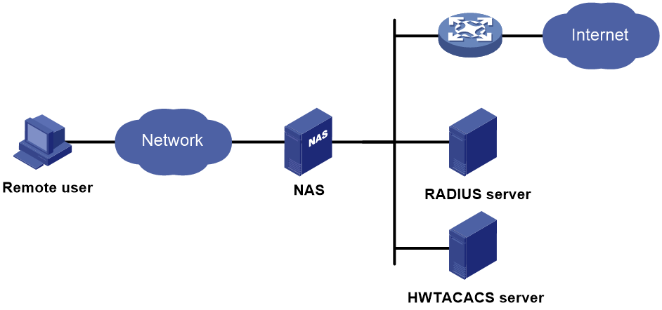
To access networks or resources beyond the NAS, a user sends its identity information to the NAS. The NAS transparently passes the user information to AAA servers and waits for the authentication, authorization, and accounting result. Based on the result, the NAS determines whether to permit or deny the access request.
AAA has various implementations, including HWTACACS, LDAP, and RADIUS. RADIUS is most often used.
You can use different servers to implement different security functions. For example, you can use an HWTACACS server for authentication and authorization, and use a RADIUS server for accounting.
You can choose the security functions provided by AAA as needed. For example, if your company wants employees to be authenticated before they access specific resources, you would deploy an authentication server. If network usage information is needed, you would also configure an accounting server.
The device performs dynamic password authentication.
RADIUS
Remote Authentication Dial-In User Service (RADIUS) is a distributed information interaction protocol that uses a client/server model. The protocol can protect networks against unauthorized access and is often used in network environments that require both high security and remote user access.
The RADIUS authorization process is combined with the RADIUS authentication process, and user authorization information is piggybacked in authentication responses. RADIUS uses UDP port 1812 for authentication and UDP port 1813 for accounting.
RADIUS was originally designed for dial-in user access, and has been extended to support additional access methods, such as Ethernet and ADSL.
Client/server model
The RADIUS client runs on the NASs located throughout the network. It passes user information to RADIUS servers and acts on the responses to, for example, reject or accept user access requests.
The RADIUS server runs on the computer or workstation at the network center and maintains information related to user authentication and network service access.
The RADIUS server operates using the following process:
1. Receives authentication, authorization, and accounting requests from RADIUS clients.
2. Performs user authentication, authorization, or accounting.
3. Returns user access control information (for example, rejecting or accepting the user access request) to the clients.
The RADIUS server can also act as the client of another RADIUS server to provide authentication proxy services.
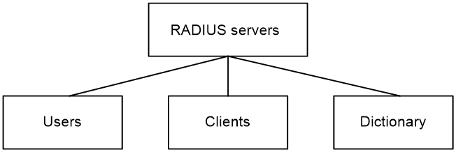
The RADIUS server maintains the following databases:
· Users—Stores user information, such as the usernames, passwords, applied protocols, and IP addresses.
· Clients—Stores information about RADIUS clients, such as shared keys and IP addresses.
· Dictionary—Stores RADIUS protocol attributes and their values.
Figure 2 RADIUS server databases
Information exchange security mechanism
The RADIUS client and server exchange information between them with the help of shared keys, which are preconfigured on the client and server. A RADIUS packet has a 16-byte field called Authenticator. This field includes a signature generated by using the MD5 algorithm, the shared key, and some other information. The receiver of the packet verifies the signature and accepts the packet only when the signature is correct. This mechanism ensures the security of information exchanged between the RADIUS client and server.
The shared keys are also used to encrypt user passwords that are included in RADIUS packets.
User authentication methods
The RADIUS server supports multiple user authentication methods, such as PAP, CHAP, and EAP.
Basic RADIUS packet exchange process
Figure 3 illustrates the interactions between a user host, the RADIUS client, and the RADIUS server.
Figure 3 Basic RADIUS packet exchange process
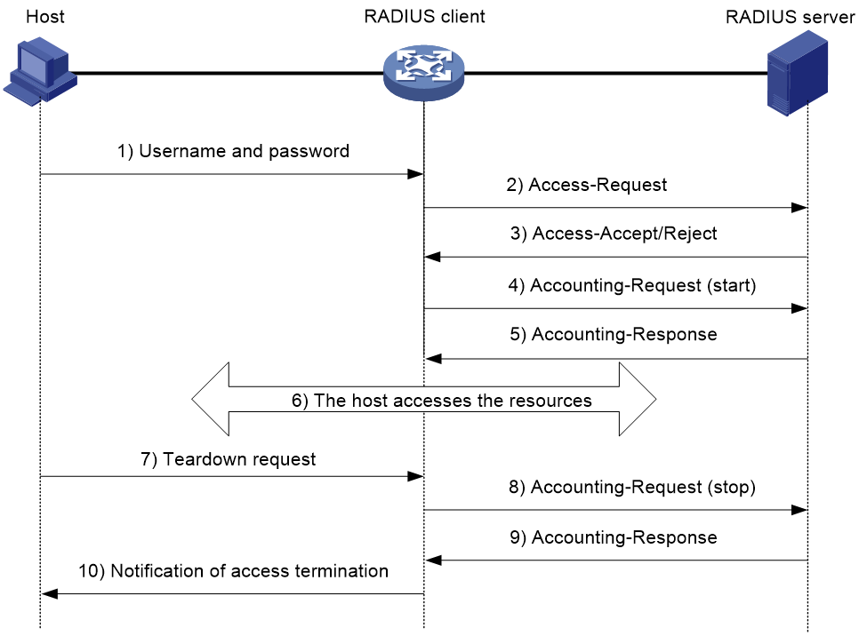
RADIUS uses in the following workflow:
1. The host sends a connection request that includes the user's username and password to the RADIUS client.
2. The RADIUS client sends an authentication request (Access-Request) to the RADIUS server. The request includes the user's password, which has been processed by the MD5 algorithm and shared key.
3. The RADIUS server authenticates the username and password. If the authentication succeeds, the server sends back an Access-Accept packet that contains the user's authorization information. If the authentication fails, the server returns an Access-Reject packet.
4. The RADIUS client permits or denies the user according to the authentication result. If the result permits the user, the RADIUS client sends a start-accounting request (Accounting-Request) packet to the RADIUS server.
5. The RADIUS server returns an acknowledgment (Accounting-Response) packet and starts accounting.
6. The user accesses the network resources.
7. The host requests the RADIUS client to tear down the connection.
8. The RADIUS client sends a stop-accounting request (Accounting-Request) packet to the RADIUS server.
9. The RADIUS server returns an acknowledgment (Accounting-Response) and stops accounting for the user.
10. The RADIUS client notifies the user of the termination.
RADIUS packet format
RADIUS uses UDP to transmit packets. The protocol also uses a series of mechanisms to ensure smooth packet exchange between the RADIUS server and the client. These mechanisms include the timer mechanism, the retransmission mechanism, and the backup server mechanism.
Figure 4 RADIUS packet format
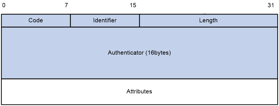
Descriptions of the fields are as follows:
· The Code field (1 byte long) indicates the type of the RADIUS packet. Table 1 gives the main values and their meanings.
Table 1 Main values of the Code field
|
Code |
Packet type |
Description |
|
1 |
Access-Request |
From the client to the server. A packet of this type includes user information for the server to authenticate the user. It must contain the User-Name attribute and can optionally contain the attributes of NAS-IP-Address, User-Password, and NAS-Port. |
|
2 |
Access-Accept |
From the server to the client. If all attribute values included in the Access-Request are acceptable, the authentication succeeds, and the server sends an Access-Accept response. |
|
3 |
Access-Reject |
From the server to the client. If any attribute value included in the Access-Request is unacceptable, the authentication fails, and the server sends an Access-Reject response. |
|
4 |
Accounting-Request |
From the client to the server. A packet of this type includes user information for the server to start or stop accounting for the user. The Acct-Status-Type attribute in the packet indicates whether to start or stop accounting. |
|
5 |
Accounting-Response |
From the server to the client. The server sends a packet of this type to notify the client that it has received the Accounting-Request and has successfully recorded the accounting information. |
· The Identifier field (1 byte long) is used to match response packets with request packets and to detect duplicate request packets. The request and response packets of the same exchange process for the same purpose (such as authentication or accounting) have the same identifier.
· The Length field (2 bytes long) indicates the length of the entire packet (in bytes), including the Code, Identifier, Length, Authenticator, and Attributes fields. Bytes beyond this length are considered padding and are ignored by the receiver. If the length of a received packet is less than this length, the packet is dropped.
· The Authenticator field (16 bytes long) is used to authenticate responses from the RADIUS server and to encrypt user passwords. There are two types of authenticators: request authenticator and response authenticator.
· The Attributes field (variable in length) includes authentication, authorization, and accounting information. This field can contain multiple attributes, each with the following subfields:
¡ Type—Type of the attribute.
¡ Length—Length of the attribute in bytes, including the Type, Length, and Value subfields.
¡ Value—Value of the attribute. Its format and content depend on the Type subfield.
Extended RADIUS attributes
The RADIUS protocol features excellent extensibility. The Vendor-Specific attribute (attribute 26) allows a vendor to define extended attributes. The extended attributes can implement functions that the standard RADIUS protocol does not provide.
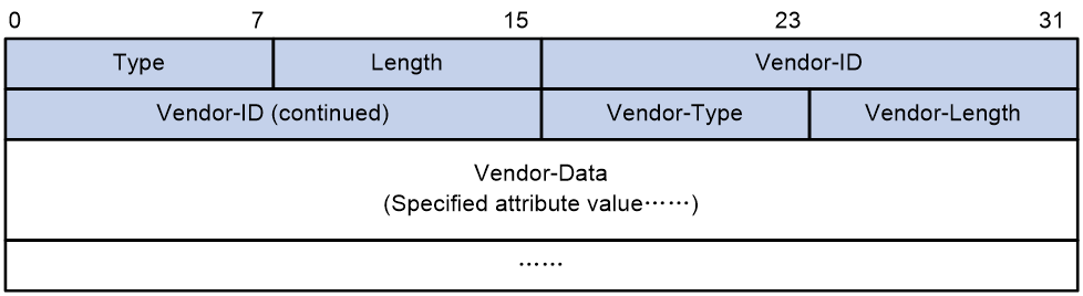
A vendor can encapsulate multiple subattributes in the TLV format in attribute 26 to provide extended functions. As shown in Figure 5, a subattribute encapsulated in attribute 26 consists of the following parts:
· Vendor-ID—ID of the vendor. The most significant byte is 0. The other three bytes contains a code compliant to RFC 1700.
· Vendor-Type—Type of the subattribute.
· Vendor-Length—Length of the subattribute.
· Vendor-Data—Contents of the subattribute.
The device supports RADIUS subattributes with a vendor ID of 25506. For more information, see "Appendix C RADIUS subattributes (vendor ID 25506)."
Figure 5 Format of attribute 26
HWTACACS
HWTACACS typically provides AAA services for PPP, VPDN, and terminal users. In a typical HWTACACS scenario, terminal users need to log in to the NAS. Working as the HWTACACS client, the NAS sends users' usernames and passwords to the HWTACACS server for authentication. After passing authentication and obtaining authorized rights, a user logs in to the device and performs operations. The HWTACACS server records the operations that each user performs.
Differences between HWTACACS and RADIUS
HWTACACS and RADIUS have many features in common, such as using a client/server model, using shared keys for data encryption, and providing flexibility and scalability. Table 2 lists the primary differences between HWTACACS and RADIUS.
Table 2 Primary differences between HWTACACS and RADIUS
|
HWTACACS |
RADIUS |
|
Uses TCP, which provides reliable network transmission. |
Uses UDP, which provides high transport efficiency. |
|
Encrypts the entire packet except for the HWTACACS header. |
Encrypts only the user password field in an authentication packet. |
|
Protocol packets are complicated and authorization is independent of authentication. Authentication and authorization can be deployed on different HWTACACS servers. |
Protocol packets are simple and the authorization process is combined with the authentication process. |
|
Supports authorization of configuration commands. Access to commands depends on both the user's roles and authorization. A user can use only commands that are permitted by the user roles and authorized by the HWTACACS server. |
Does not support authorization of configuration commands. Access to commands solely depends on the user's roles. For more information about user roles, see Fundamentals Configuration Guide. |
Basic HWTACACS packet exchange process
Figure 6 describes how HWTACACS performs user authentication, authorization, and accounting for a Telnet user.
Figure 6 Basic HWTACACS packet exchange process for a Telnet user

HWTACACS operates using in the following workflow:
1. A Telnet user sends an access request to the HWTACACS client.
2. The HWTACACS client sends a start-authentication packet to the HWTACACS server when it receives the request.
3. The HWTACACS server sends back an authentication response to request the username.
4. Upon receiving the response, the HWTACACS client asks the user for the username.
5. The user enters the username.
6. After receiving the username from the user, the HWTACACS client sends the server a continue-authentication packet that includes the username.
7. The HWTACACS server sends back an authentication response to request the login password.
8. Upon receipt of the response, the HWTACACS client prompts the user for the login password.
9. The user enters the password.
10. After receiving the login password, the HWTACACS client sends the HWTACACS server a continue-authentication packet that includes the login password.
11. If the authentication succeeds, the HWTACACS server sends back an authentication response to indicate that the user has passed authentication.
12. The HWTACACS client sends a user authorization request packet to the HWTACACS server.
13. If the authorization succeeds, the HWTACACS server sends back an authorization response, indicating that the user is now authorized.
14. Knowing that the user is now authorized, the HWTACACS client pushes its CLI to the user and permits the user to log in.
15. The HWTACACS client sends a start-accounting request to the HWTACACS server.
16. The HWTACACS server sends back an accounting response, indicating that it has received the start-accounting request.
17. The user logs off.
18. The HWTACACS client sends a stop-accounting request to the HWTACACS server.
19. The HWTACACS server sends back a stop-accounting response, indicating that the stop-accounting request has been received.
LDAP
The Lightweight Directory Access Protocol (LDAP) provides standard multiplatform directory service. LDAP was developed on the basis of the X.500 protocol. It improves the following functions of X.500:
· Read/write interactive access.
· Browse.
· Search.
LDAP is suitable for storing data that does not often change. The protocol is used to store user information. For example, LDAP server software Active Directory Server is used in Microsoft Windows operating systems. The software stores the user information and user group information for user login authentication and authorization.
LDAP directory service
LDAP uses directories to maintain the organization information, personnel information, and resource information. The directories are organized in a tree structure and include entries. An entry is a set of attributes with distinguished names (DNs). The attributes are used to store information such as usernames, passwords, emails, computer names, and phone numbers.
LDAP uses a client/server model, and all directory information is stored in the LDAP server. Commonly used LDAP server products include Microsoft Active Directory Server, IBM Tivoli Directory Server, and Sun ONE Directory Server.
LDAP authentication and authorization
AAA can use LDAP to provide authentication and authorization services for users. LDAP defines a set of operations to implement its functions. The main operations for authentication and authorization are the bind operation and search operation.
· The bind operation allows an LDAP client to perform the following operations:
¡ Establish a connection with the LDAP server.
¡ Obtain the access rights to the LDAP server.
¡ Check the validity of user information.
· The search operation constructs search conditions and obtains the directory resource information of the LDAP server.
In LDAP authentication, the client completes the following tasks:
1. Uses the LDAP server administrator DN to bind with the LDAP server. After the binding is created, the client establishes a connection to the server and obtains the right to search.
2. Constructs search conditions by using the username in the authentication information of a user. The specified root directory of the server is searched and a user DN list is generated.
3. Binds with the LDAP server by using each user DN and password. If a binding is created, the user is considered legal.
In LDAP authorization, the client performs the same tasks as in LDAP authentication. When the client constructs search conditions, it obtains both authorization information and the user DN list.
Basic LDAP authentication process
The following example illustrates the basic LDAP authentication process for a Telnet user.
Figure 7 Basic LDAP authentication process for a Telnet user
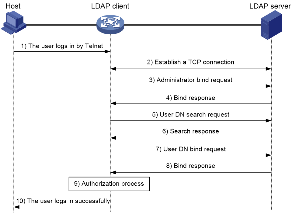
The following shows the basic LDAP authentication process:
1. A Telnet user initiates a connection request and sends the username and password to the LDAP client.
2. After receiving the request, the LDAP client establishes a TCP connection with the LDAP server.
3. To obtain the right to search, the LDAP client uses the administrator DN and password to send an administrator bind request to the LDAP server.
4. The LDAP server processes the request. If the bind operation is successful, the LDAP server sends an acknowledgment to the LDAP client.
5. The LDAP client sends a user DN search request with the username of the Telnet user to the LDAP server.
6. After receiving the request, the LDAP server searches for the user DN by the base DN, search scope, and filtering conditions. If a match is found, the LDAP server sends a response to notify the LDAP client of the successful search. There might be one or more user DNs found.
7. The LDAP client uses the obtained user DN and the entered user password as parameters to send a user DN bind request to the LDAP server. The server will check whether the user password is correct.
8. The LDAP server processes the request, and sends a response to notify the LDAP client of the bind operation result. If the bind operation fails, the LDAP client uses another obtained user DN as the parameter to send a user DN bind request to the LDAP server. This process continues until a DN is bound successfully or all DNs fail to be bound. If all user DNs fail to be bound, the LDAP client notifies the user of the login failure and denies the user's access request.
9. The LDAP client saves the user DN that has been bound and exchanges authorization packets with the authorization server.
If LDAP authorization is used, see the authorization process shown in Figure 8.
If another method is expected for authorization, the authorization process of that method applies.
10. After successful authorization, the LDAP client notifies the user of the successful login.
Basic LDAP authorization process
The following example illustrates the basic LDAP authorization process for a Telnet user.
Figure 8 Basic LDAP authorization process for a Telnet user
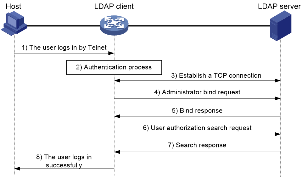
The following shows the basic LDAP authorization process:
1. A Telnet user initiates a connection request and sends the username and password to the device. The device will act as the LDAP client during authorization.
2. After receiving the request, the device exchanges authentication packets with the authentication server for the user:
¡ If LDAP authentication is used, see the authentication process shown in Figure 7.
- If the device (the LDAP client) uses the same LDAP server for authentication and authorization, skip to step 6.
- If the device (the LDAP client) uses different LDAP servers for authentication and authorization, skip to step 4.
¡ If another authentication method is used, the authentication process of that method applies. The device acts as the LDAP client. Skip to step 3.
3. The LDAP client establishes a TCP connection with the LDAP authorization server.
4. To obtain the right to search, the LDAP client uses the administrator DN and password to send an administrator bind request to the LDAP server.
5. The LDAP server processes the request. If the bind operation is successful, the LDAP server sends an acknowledgment to the LDAP client.
6. The LDAP client sends an authorization search request with the username of the Telnet user to the LDAP server. If the user uses the same LDAP server for authentication and authorization, the client sends the request with the saved user DN of the Telnet user to the LDAP server.
7. After receiving the request, the LDAP server searches for the user information by the base DN, search scope, filtering conditions, and LDAP attributes. If a match is found, the LDAP server sends a response to notify the LDAP client of the successful search.
8. After successful authorization, the LDAP client notifies the user of the successful login.
User management based on ISP domains and user access types
AAA manages users based on the users' ISP domains and access types.
On a NAS, each user belongs to one ISP domain. The NAS determines the ISP domain to which a user belongs based on the username entered by the user at login.
Figure 9 Determining the ISP domain for a user by username
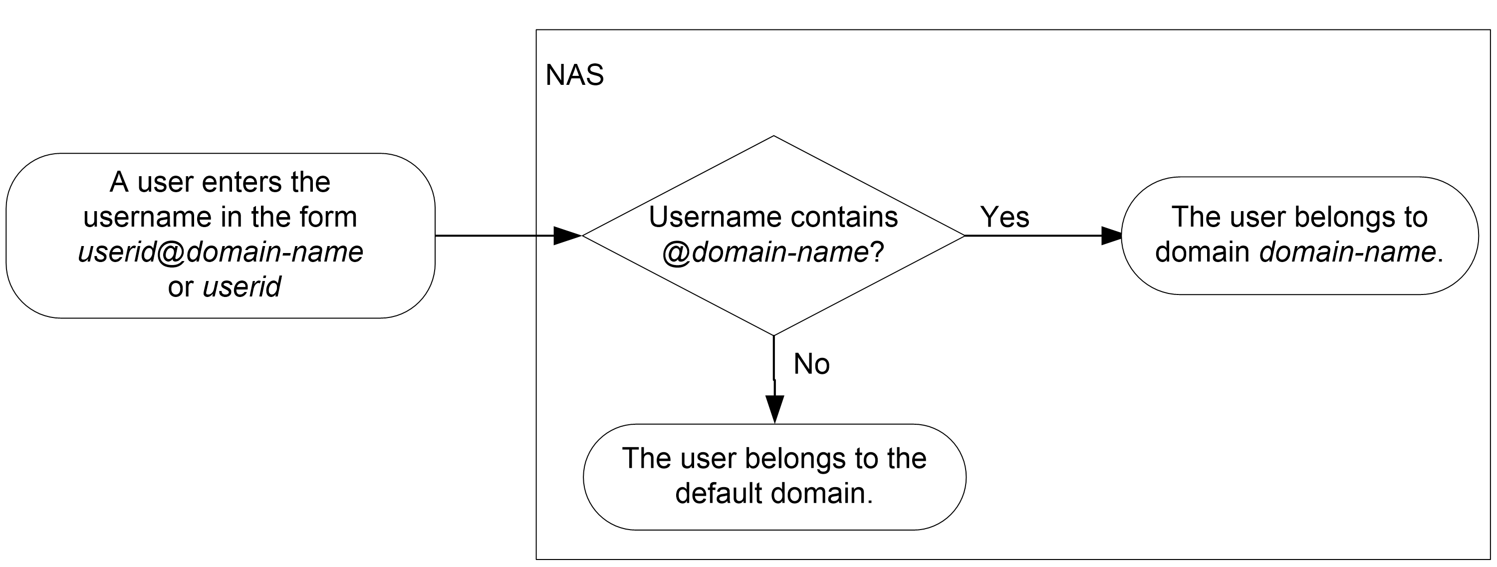
AAA manages users in the same ISP domain based on the users' access types. The device supports the following user access types:
· LAN—LAN users must pass 802.1X or MAC authentication to come online.
· Login—Login users include SSH, Telnet, FTP, and terminal users that log in to the device. Terminal users can access through a virtual console port.
· Portal—Portal users must pass portal authentication to access the network.
· PPP.
· IKE—IKE users must pass IKE extended authentication to access the network.
· HTTP/HTTPS—Users log in to the device through HTTP or HTTPS.
The device also provides authentication modules (such as 802.1X) for implementation of user authentication management policies. If you configure these authentication modules, the ISP domains for users of the access types depend on the configuration of the authentication modules.
Authentication, authorization, and accounting methods
AAA supports configuring different authentication, authorization, and accounting methods for different types of users in an ISP domain. The NAS determines the ISP domain and access type of a user. The NAS also uses the methods configured for the access type in the domain to control the user's access.
AAA also supports configuring a set of default methods for an ISP domain. These default methods are applied to users for whom no AAA methods are configured.
Authentication methods
The device supports the following authentication methods:
· No authentication—This method trusts all users and does not perform authentication. For security purposes, do not use this method.
· Local authentication—The NAS authenticates users by itself, based on the locally configured user information including the usernames, passwords, and attributes. Local authentication allows high speed and low cost, but the amount of information that can be stored is limited by the size of the storage space.
· Remote authentication—The NAS works with a remote server to authenticate users. The NAS communicates with the remote server through the RADIUS, LDAP, or HWTACACS protocol. The server manages user information in a centralized manner. Remote authentication provides high capacity, reliable, and centralized authentication services for multiple NASs. You can configure backup methods to be used when the remote server is not available.
Authorization methods
The device supports the following authorization methods:
· No authorization—The NAS performs no authorization exchange. The following default authorization information applies after users pass authentication:
¡ Login users obtain the level-0 user role. For more information about the level-0 user role, see RBAC configuration in Fundamentals Configuration Guide.
¡ The working directory for FTP, SFTP, and SCP login users is the root directory of the NAS. However, the users do not have permission to access the root directory.
¡ Non-login users can access the network.
· Local authorization—The NAS performs authorization according to the user attributes locally configured for users.
· Remote authorization—The NAS works with a remote server to authorize users. RADIUS authorization is bound with RADIUS authentication. RADIUS authorization can work only after RADIUS authentication is successful, and the authorization information is included in the Access-Accept packet. HWTACACS or LDAP authorization is separate from authentication, and the authorization information is included in the authorization response after successful authentication. You can configure backup methods to be used when the remote server is not available.
Accounting methods
The device supports the following accounting methods:
· No accounting—The NAS does not perform accounting for the users.
· Local accounting—Local accounting is implemented on the NAS. It counts and controls the number of concurrent users that use the same local user account, but does not provide statistics for charging.
· Remote accounting—The NAS works with a remote server for accounting. You can configure backup methods to be used when the remote server is not available.
AAA extended functions
The device provides the following login services to enhance device security:
· Command authorization—Enables the NAS to let the authorization server determine whether a command entered by a login user is permitted. Login users can execute only commands permitted by the authorization server. For more information about command authorization, see Fundamentals Configuration Guide.
· Command accounting—When command authorization is disabled, command accounting enables the accounting server to record all valid commands executed on the device. When command authorization is enabled, command accounting enables the accounting server to record all authorized commands. For more information about command accounting, see Fundamentals Configuration Guide.
· User role authentication—Authenticates each user that wants to obtain another user role without logging out or getting disconnected. For more information about user role authentication, see Fundamentals Configuration Guide.
RADIUS server feature of the device
Enable the RADIUS server feature of the device to work with RADIUS clients for user authentication and authorization. The device can act as a dedicated RADIUS server or as both a RADIUS server and a RADIUS client at the same time.
The RADIUS server feature provides for flexible networks with less cost. As shown in Figure 10, Device A provides RADIUS server functions at the distribution layer; Device B and Device C are configured with RADIUS schemes to implement user authentication and authorization at the access layer.
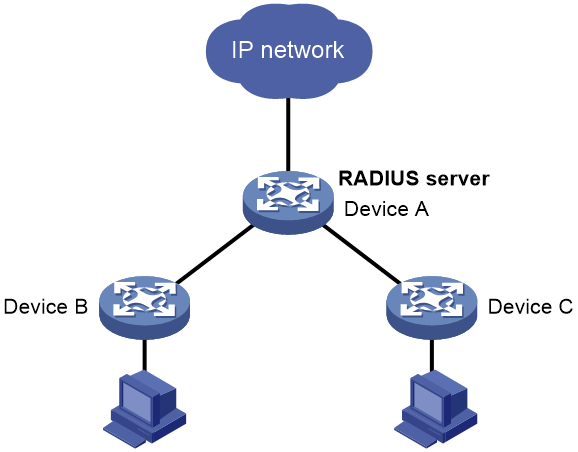
The RADIUS server feature supports the following operations:
· Manages RADIUS user data, which is generated from local user information and includes user name, password, description, authorization ACL, authorization VLAN, and expiration time.
· Manages RADIUS clients. You can add, modify, and delete RADIUS clients. A RADIUS client is identified by the IP address, and it includes attribute information such as the shared key. The RADIUS server feature processes authentication requests only from the managed RADIUS clients and ignores requests from unknown clients.
· Authenticates and authorizes users of the network access type. The server does not provide accounting.
· Uses an LDAP server instead of local user information to authenticate users.
· Provides PAP, CHAP, and EAP authentication methods.
When the RADIUS server receives a RADIUS packet, it performs the following actions:
1. Verifies that the packet is sent from a managed RADIUS client.
2. Verifies the packet with the shared key.
3. Verifies that the user account exists, the password is correct, and other attributes meet the requirements (for example, the account is in the validity period).
4. Determines the authentication result and authorizes specific privileges to the authenticated user.
The RADIUS server feature of the device has the following restrictions:
· The authentication port is fixed at UDP 1812 and cannot be modified.
· The feature is supported on IPv4 networks, but not on IPv6 networks.
· Usernames sent to the RADIUS server cannot include a domain name.
Protocols and standards
· RFC 2865, Remote Authentication Dial In User Service (RADIUS)
· RFC 2866, RADIUS Accounting
· RFC 2867, RADIUS Accounting Modifications for Tunnel Protocol Support
· RFC 2868, RADIUS Attributes for Tunnel Protocol Support
· RFC 2869, RADIUS Extensions
· RFC 3576, Dynamic Authorization Extensions to Remote Authentication Dial In User Service (RADIUS)
· RFC 4818, RADIUS Delegated-IPv6-Prefix Attribute
· RFC 5176, Dynamic Authorization Extensions to Remote Authentication Dial In User Service (RADIUS)
· RFC 1492, An Access Control Protocol, Sometimes Called TACACS
· RFC 1777, Lightweight Directory Access Protocol
· RFC 2251, Lightweight Directory Access Protocol (v3)
AAA tasks at a glance
To configure AAA, perform the following tasks:
1. Configuring AAA schemes
If local authentication is used, configure local users and the related attributes. If remote authentication is used, configure the required RADIUS, LDAP, or HWTACACS schemes.
2. Configuring an ISP domain
b. Configuring ISP domain attributes
3. Configuring AAA methods for an ISP domain
Configure authentication, authorization, and accounting methods for an ISP domain as needed. These methods use existing AAA schemes.
¡ Configuring authentication methods for an ISP domain
¡ Configuring authorization methods for an ISP domain
¡ Configuring accounting methods for an ISP domain
4. (Optional.) Configuring advanced AAA features
¡ Setting the maximum number of concurrent login users
¡ Configuring local BYOD authorization
¡ Configuring and applying an ITA policy
¡ Enabling password change prompt logging
Configuring local users
About local users
To implement local authentication, authorization, and accounting, create local users and configure user attributes on the device. The local users and attributes are stored in the local user database on the device. A local user is uniquely identified by the combination of a username and a user type.
Local users are classified into the following types:
· Device management user—User that logs in to the device for device management.
· Network access user—User that accesses network resources through the device.
Network access users also include guests that access the network temporarily. Guests can use only LAN and portal services.
The following shows the configurable local user attributes:
· Description—Descriptive information of the user.
· Service type—Services that the user can use. Local authentication checks the service types of a local user. If none of the service types is available, the user cannot pass authentication.
· User state—Whether or not a local user can request network services. There are two user states: active and blocked. A user in active state can request network services, but a user in blocked state cannot.
· Upper limit of concurrent logins using the same user name—Maximum number of users that can concurrently access the device by using the same user name. When the number reaches the upper limit, no more local users can access the device by using the user name.
· User group—Each local user belongs to a local user group and has all attributes of the group. The attributes include the password control attributes and authorization attributes. For more information about local user group, see "Configuring user group attributes."
· Binding attributes—Binding attributes control the scope of users, and are checked during local authentication of a user. If the attributes of a user do not match the binding attributes configured for the local user account, the user cannot pass authentication.
· Authorization attributes—Authorization attributes indicate the user's rights after it passes local authentication.
Configure the authorization attributes based on the service type of local users. For example, you do not need to configure the FTP/SFTP/SCP working directory attribute for a PPP user.
You can configure an authorization attribute in user group view or local user view. The setting of an authorization attribute in local user view takes precedence over the attribute setting in user group view.
The attribute configured in user group view takes effect on all local users in the user group.
The attribute configured in local user view takes effect only on the local user.
· Password control attributes—Password control attributes help control password security for device management users. Password control attributes include password aging time, minimum password length, password composition checking, password complexity checking, and login attempt limit.
You can configure a password control attribute in system view, user group view, or local user view. A password control attribute with a smaller effective range has a higher priority. For more information about password management and global password configuration, see "Configuring password control."
· Validity period—Time period in which a network access user is considered valid for authentication.
Local user configuration tasks at a glance
To configure local users, perform the following tasks:
1. Configuring local user attributes
¡ Configuring attributes for device management users
¡ Configuring attributes for network access users
¡ Configuring local guest attributes
2. (Optional.) Configuring user group attributes
3. (Optional.) Managing local guests
Configuring attributes for device management users
Restrictions and guidelines
If password control is enabled globally by using the password-control enable command, the device does not display local user passwords or retain them in the running configuration. When you globally disable the password control feature, local user passwords are automatically restored to the running configuration. To display the running configuration, use the display current-configuration command.
You can configure authorization attributes and password control attributes in local user view or user group view. The setting in local user view takes precedence over the setting in user group view.
Procedure
1. Enter system view.
system-view
2. Add a device management user and enter device management user view.
local-user user-name class manage
3. Configure a password for the device management user.
password [ { hash | simple } string ]
A non-password-protected user passes authentication if the user provides the correct username and passes attribute checks. To enhance security, configure a password for each device management user.
4. Assign services to the device management user.
service-type { ftp | { http | https | ssh | telnet | terminal } * }
By default, no services are authorized to a device management user.
5. (Optional.) Set the status of the device management user.
state { active | block }
By default, a device management user is in active state and can request network services.
6. (Optional.) Set the upper limit of concurrent logins using the device management username.
access-limit max-user-number
By default, the number of concurrent logins is not limited for a device management user.
This command takes effect only when local accounting is configured for device management users. This command does not apply to FTP, SFTP, or SCP users that do not support accounting.
7. (Optional.) Configure authorization attributes for the device management user.
authorization-attribute { idle-cut minutes | user-role role-name | work-directory directory-name } *
The following default settings apply:
¡ The working directory for FTP, SFTP, and SCP users is the root directory of the NAS. However, the users do not have permission to access the root directory.
¡ The network-operator user role is assigned to local users that are created by a network-admin or level-15 user.
8. (Optional.) Configure password control attributes for the device management user. Choose the following tasks as needed:
¡ Set the password aging time.
password-control aging aging-time
¡ Set the minimum password length.
password-control length length
¡ Configure the password composition policy.
password-control composition type-number type-number [ type-length type-length ]
¡ Configure the password complexity checking policy.
password-control complexity { same-character | user-name } check
¡ Configure the maximum login attempts and the action to take if there is a login failure.
password-control login-attempt login-times [ exceed { lock | lock-time time | unlock } ]
By default, a device management user uses password control attributes of the user group to which the user belongs.
9. (Optional.) Assign the device management user to a user group.
group group-name
By default, a device management user belongs to user group system.
Configuring attributes for network access users
Restrictions and guidelines
You can configure authorization attributes in local user view or user group view. The setting in local user view takes precedence over the setting in user group view.
Configure the location binding attribute based on the service types of users.
· For 802.1X users, specify the 802.1X-enabled Layer 2 Ethernet interfaces through which the users access the device.
· For MAC authentication users, specify the MAC authentication-enabled Layer 2 Ethernet interfaces through which the users access the device.
· For portal users, specify the portal-enabled interfaces through which the users access the device. Specify the Layer 2 Ethernet interfaces if portal is enabled on VLAN interfaces and the portal roaming enable command is not used.
Procedure
1. Enter system view.
system-view
2. Add a network access user and enter network access user view.
local-user user-name class network
3. (Optional.) Configure a password for the network access user.
password { cipher | simple } string
4. (Optional.) Configure a description for the network access user.
description text
By default, no description is configured for a local user.
5. Assign services to the network access user.
service-type { ike | lan-access | portal | ppp }
By default, no services are authorized to a network access user.
6. (Optional.) Set the status of the network access user.
state { active | block }
By default, a network access user is in active state and can request network services.
7. (Optional.) Set the upper limit of concurrent logins using the network access username.
access-limit max-user-number
By default, the number of concurrent logins is not limited for a network access user.
8. (Optional.) Configure binding attributes for the network access user.
bind-attribute { call-number call-number [ : subcall-number ] | ip ip-address | location interface interface-type interface-number | mac mac-address | vlan vlan-id } *
By default, no binding attributes are configured for a network access user.
9. (Optional.) Configure authorization attributes for the network access user.
authorization-attribute { acl acl-number | callback-number callback-number | idle-cut minutes | ip ipv4-address | ip-pool ipv4-pool-name | ipv6 ipv6-address | ipv6-pool ipv6-pool-name | ipv6-prefix ipv6-prefix prefix-length | { primary-dns | secondary-dns } { ip ipv4-address | ipv6 ipv6-address } | session-timeout minutes | url url-string | user-profile profile-name | vlan vlan-id } *
By default, a network access user does not have authorization attributes.
10. (Optional.) Assign the network access user to a user group.
group group-name
By default, a network access user belongs to user group system.
11. (Optional.) specify the validity period for the local user.
validity-datetime { from start-date start-time to expiration-date expiration-time | from start-date start-time | to expiration-date expiration-time }
By default, the validity period for a network access user does not expire.
Configuring local guest attributes
About this task
Create local guests and configure guest attributes to control temporary network access behavior. Guests can access the network after passing local authentication. You can configure the recipient addresses and email attribute information to the local guests and guest sponsors.
Procedure
1. Enter system view.
system-view
2. Create a local guest and enter local guest view.
local-user user-name class network guest
3. (Optional.) Configure a password for the local guest.
password { cipher | simple } string
4. Configure basic information for the local guest. Choose the following tasks as needed:
¡ Configure a description for the local guest.
description text
By default, no description is configured for a local guest.
¡ Specify the name of the local guest.
full-name name-string
By default, no name is specified for a local guest.
¡ Specify the company of the local guest.
company company-name
By default, no company is specified for a local guest.
¡ Specify the phone number of the local guest.
phone phone-number
By default, no phone number is specified for a local guest.
¡ Specify the email address of the local guest.
email email-string
By default, no email address is specified for a local guest.
¡ Specify the sponsor name for the local guest.
sponsor-full-name name-string
By default, no sponsor name is specified for a local guest.
¡ Specify the sponsor department for the local guest.
sponsor-department department-string
By default, no sponsor department is specified for a local guest.
¡ Specify the sponsor email address for the local guest.
sponsor-email email-string
By default, no sponsor email address is specified for a local guest.
5. (Optional.) Configure the validity period for the local guest.
validity-datetime from start-date start-time to expiration-date expiration-time
By default, a local guest does not expire.
6. (Optional.) Assign the local guest to a user group.
group group-name
By default, a local guest belongs to the system-defined user group system.
7. (Optional.) Configure the local guest status.
state { active | block }
By default, a local guest is in active state and is allowed to request network services.
Configuring user group attributes
About this task
User groups simplify local user configuration and management. A user group contains a group of local users and has a set of local user attributes. You can configure local user attributes for a user group to implement centralized user attributes management for the local users in the group. Local user attributes that are manageable include authorization attributes.
Procedure
1. Enter system view.
system-view
2. Create a user group and enter user group view.
user-group group-name
By default, a system-defined user group exists. The group name is system.
3. Configure authorization attributes for the user group.
authorization-attribute { acl acl-number | callback-number callback-number | idle-cut minutes | ip-pool ipv4-pool-name | ipv6-pool ipv6-pool-name | ipv6-prefix ipv6-prefix prefix-length | { primary-dns | secondary-dns } { ip ipv4-address | ipv6 ipv6-address } | session-timeout minutes | url url-string | user-profile profile-name | vlan vlan-id | work-directory directory-name } *
By default, no authorization attributes are configured for a user group.
4. Configure authorization attributes for a type of BYOD endpoints in the user group.
byod authorization device-type type-name { acl acl-number | callback-number callback-number | idle-cut minutes | ip-pool ipv4-pool-name | ipv6-pool ipv6-pool-name | ipv6-prefix ipv6-prefix prefix-length | { primary-dns | secondary-dns } { ip ipv4-address | ipv6 ipv6-address } | session-timeout minutes | url url-string | user-profile profile-name | vlan vlan-id } *
By default, no authorization attributes are configured for any type of BYOD endpoints in the user group.
The attributes apply to local BYOD authorization and take effect only on network access users.
5. (Optional.) Configure password control attributes for the user group. Choose the following tasks as needed:
¡ Set the password aging time.
password-control aging aging-time
¡ Set the minimum password length.
password-control length length
¡ Configure the password composition policy.
password-control composition type-number type-number [ type-length type-length ]
¡ Configure the password complexity checking policy.
password-control complexity { same-character | user-name } check
¡ Configure the maximum login attempts and the action to take for login failures.
password-control login-attempt login-times [ exceed { lock | lock-time time | unlock } ]
By default, a user group uses the global password control settings. For more information, see "Configuring password control."
Password control attributes are applicable only to device management users.
Managing local guests
About this task
The local guest management features are for registration, approval, maintenance, and access control of local guests.
The registration and approval processes are as follows:
1. The device pushes the portal user registration page to a user that wants to access the network as a local guest.
2. The user submits account information for registration, including the user name, password, and email address.
3. The device forwards the registration request to the guest manager in an email notification.
4. The guest manager adds supplementary information as needed and approves the registration information.
The guest manager must process the registration request before the waiting-approval timeout timer expires. The device automatically deletes expired registration request information.
5. The device creates a local guest account and sends an email notification to the user and guest sponsor. The email contains local guest account, password, validity period, and other account information.
The user can access the network as a local guest.
The device provides the following local guest management features:
· Registration and approval—The device creates local guests after the guest registration information is approved by a guest manager.
· Email notification—The device notifies the local guests, guest sponsors, or guest managers by email of the guest account information or guest registration requests.
· Local guest creation in batch—Create a batch of local guests.
· Local guest import—Import guest account information from a .csv file to create local guests on the device based on the imported information.
· Local guest export—Export local guest account information to a .csv file. You can import the account information to other devices as needed.
· Guest auto-delete—The device checks the validity status of each local guest and automatically deletes expired local guests.
Procedure
1. Enter system view
system-view
2. Configure the email notification feature for local guests.
a. Configure the subject and body of email notifications.
local-guest email format to { guest | manager | sponsor } { body body-string | subject sub-string }
By default, no subject or body is configured.
b. Configure the email sender address in the email notifications sent by the device for local guests.
local-guest email sender email-address
By default, no email sender address is configured for the email notifications sent by the device.
c. Specify an SMTP server for sending email notifications of local guests.
local-guest email smtp-server url-string
By default, no SMTP server is specified.
3. Configure the guest manager's email address.
local-guest manager-email email-address
By default, the guest manager's email address is not configured.
4. (Optional.) Set the waiting-approval timeout timer for guest registration requests.
local-guest timer waiting-approval time-value
By default, the waiting-approval timeout timer for guest registration requests is 24 hours.
5. (Optional.) Import guest account information from a .csv file in the specified path to create local guests based on the imported information.
local-user-import class network guest url url-string validity-datetime start-date start-time to expiration-date expiration-time [ auto-create-group | override | start-line line-number ] *
6. (Optional.) Create local guests in batch.
local-guest generate username-prefix name-prefix [ password-prefix password-prefix ] suffix suffix-number [ group group-name ] count user-count validity-datetime start-date start-time to expiration-date expiration-time
Batch generated local guests share the same name prefix. You can also configure a password prefix to be shared by the guests.
7. (Optional.) Export local guest account information to a .csv file in the specified path.
local-user-export class network guest url url-string
8. (Optional.) Enable the guest auto-delete feature.
local-guest auto-delete enable
By default, the guest auto-delete feature is disabled.
9. (Optional.) Send email notifications to the local guest or the guest sponsor.
a. Return to user view.
quit
b. Send email notifications to the local guest or the guest sponsor. The email contents include the user name, password, and validity period of the guest account.
local-guest send-email user-name user-name to { guest | sponsor }
Display and maintenance commands for local users and local user groups
Execute display commands in any view and reset commands in user view.
|
Task |
Command |
|
Display pending registration requests for local guests. |
display local-guest waiting-approval [ user-name user-name ] |
|
Display the local user configuration and online user statistics. |
display local-user [ class { manage | network [ guest ] } | idle-cut { disable | enable } | service-type { ftp | http | https | ike | lan-access | portal | ppp | ssh | telnet | terminal } | state { active | block } | user-name user-name class { manage | network [ guest ] } | vlan vlan-id ] |
|
Display user group configuration. |
display user-group { all | name group-name [ byod-authorization ] } |
|
Clear pending registration requests for local guests. |
reset local-guest waiting-approval [ user-name user-name ] |
Configuring RADIUS
RADIUS tasks at a glance
To configure RADIUS, perform the following tasks:
1. Configuring a test profile for RADIUS server status detection
To detect the status of a RADIUS server, you must configure a test profile and configure the RADIUS server to use the test profile in a RADIUS scheme.
3. Specifying RADIUS authentication servers
4. Specifying the RADIUS accounting servers
5. Specifying the shared keys for secure RADIUS communication
Perform this task if no shared keys are specified when configuring RADIUS authentication or accounting servers.
6. (Optional.) Setting the status of RADIUS servers
7. (Optional.) Setting RADIUS timers
8. (Optional.) Configuring parameters for RADIUS packets
¡ Specifying the source IP address for outgoing RADIUS packets
¡ Setting the username format and traffic statistics units
¡ Setting the maximum number of RADIUS request transmission attempts
¡ Setting the maximum number of real-time accounting attempts
¡ Setting the DSCP priority for RADIUS packets
9. (Optional.) Configuring parameters for RADIUS attributes
¡ Configuring the Login-Service attribute check method for SSH, FTP, and terminal users
¡ Interpreting the RADIUS class attribute as CAR parameters
¡ Configuring the format of the RADIUS Called-Station-Id attribute
¡ Configuring the MAC address format for the RADIUS Called-Station-Id attribute
¡ Configuring the MAC address format for the RADIUS Calling-Station-Id attribute
¡ Specifying a server version for interoperating with servers with a vendor ID of 2011
¡ Setting the data measurement unit for the Remanent_Volume attribute
¡ Interpreting the Microsegment-Id attribute to an authorization VLAN
¡ Specifying the format for attribute Acct-Session-Id
¡ Including the proprietary H3c-DHCP-Option attribute in outgoing RADIUS packets
¡ Configuring the RADIUS attribute translation feature
¡ Using server-assigned usernames for AAA processes subsequent to authentication
10. (Optional.) Configuring extended RADIUS features
¡ Enabling the RADIUS server load sharing feature
¡ Configuring the RADIUS accounting-on feature
¡ Configuring the RADIUS session-control feature
¡ Configuring the RADIUS DAS feature
¡ Enabling SNMP notifications for RADIUS
Configuring a test profile for RADIUS server status detection
About this task
To detect the reachability of a RADIUS authentication server, specify a test profile for the RADIUS server when you specify the server in a RADIUS scheme. With the test profile, the device refreshes the RADIUS server status at the end of each detection according to the detection result. If the server is unreachable, the device sets the status of the server to blocked. If the server is reachable, the device sets the status of the server to active.
After you specify an existing test profile, the device starts to probe the server status at the probe interval by sending a simulated authentication request with the specified username to the server. After the specified number of consecutive probes finish, the device determines the server status as follows:
· If the device receives a response from the server in each probe, the device determines that the RADIUS server is reachable.
· If the device does not receive a response from the server in any probe, the device determines that the server is unreachable.
· In other situations, the device determines that the status of the server has not changed.
Restrictions and guidelines
You can configure multiple test profiles in the system.
The device stops detecting the status of a RADIUS server when one of the following operations is performed:
· The RADIUS server is removed from the RADIUS scheme.
· The test profile configuration for the RADIUS server is removed in RADIUS scheme view.
· The test profile specified for the RADIUS server is deleted.
· The RADIUS server is manually set to the blocked state.
· The RADIUS scheme that contains the RADIUS server is deleted.
Procedure
1. Enter system view.
system-view
2. Configure a test profile for detecting the status of RADIUS authentication servers.
radius-server test-profile profile-name username name [ interval interval ] [ probe-count count ]
Creating a RADIUS scheme
Restrictions and guidelines
You can configure a maximum of 16 RADIUS schemes. A RADIUS scheme can be used by multiple ISP domains.
Procedure
1. Enter system view.
system-view
2. Create a RADIUS scheme and enter RADIUS scheme view.
radius scheme radius-scheme-name
Specifying RADIUS authentication servers
About this task
A RADIUS authentication server completes authentication and authorization together, because authorization information is piggybacked in authentication responses sent to RADIUS clients.
You can specify one primary authentication server and a maximum of 16 secondary authentication servers for a RADIUS scheme. Secondary servers provide AAA services when the primary server becomes unreachable. The device searches for an active server in the order the secondary servers are configured.
When RADIUS server load sharing is enabled, the device distributes the workload over all servers without considering the primary and secondary server roles. The device checks the weight value and number of currently served users for each active server, and then determines the most appropriate server in performance to receive an authentication request.
Restrictions and guidelines
If redundancy is not required, specify only the primary server.
A RADIUS authentication server can function as the primary authentication server for one scheme and a secondary authentication server for another scheme at the same time.
Two authentication servers in a scheme, primary or secondary, cannot have the same combination of IP address and port number.
Procedure
1. Enter system view.
system-view
2. Enter RADIUS scheme view.
radius scheme radius-scheme-name
3. Specify the primary RADIUS authentication server.
primary authentication { ipv4-address | ipv6 ipv6-address } [ port-number | key { cipher | simple } string | test-profile profile-name | weight weight-value ] *
By default, no primary RADIUS authentication server is specified.
The weight keyword takes effect only when the RADIUS server load sharing feature is enabled for the RADIUS scheme.
4. (Optional.) Specify a secondary RADIUS authentication server.
secondary authentication { ipv4-address | ipv6 ipv6-address } [ port-number | key { cipher | simple } string | test-profile profile-name | weight weight-value ] *
By default, no secondary RADIUS authentication servers are specified.
The weight keyword takes effect only when the RADIUS server load sharing feature is enabled for the RADIUS scheme.
Specifying the RADIUS accounting servers
About this task
You can specify one primary accounting server and a maximum of 16 secondary accounting servers for a RADIUS scheme. Secondary servers provide AAA services when the primary server becomes unavailable. The device searches for an active server in the order the secondary servers are configured.
When RADIUS server load sharing is enabled, the device distributes the workload over all servers without considering the primary and secondary server roles. The device checks the weight value and number of currently served users for each active server, and then determines the most appropriate server in performance to receive an accounting request.
Restrictions and guidelines
If redundancy is not required, specify only the primary server.
A RADIUS accounting server can function as the primary accounting server for one scheme and a secondary accounting server for another scheme at the same time.
Two accounting servers in a scheme, primary or secondary, cannot have the same combination of IP address and port number.
RADIUS does not support accounting for FTP, SFTP, and SCP users.
Procedure
1. Enter system view.
system-view
2. Enter RADIUS scheme view.
radius scheme radius-scheme-name
3. Specify the primary RADIUS accounting server.
primary accounting { ipv4-address | ipv6 ipv6-address } [ port-number | key { cipher | simple } string | weight weight-value ] *
By default, no primary RADIUS accounting server is specified.
The weight keyword takes effect only when the RADIUS server load sharing feature is enabled for the RADIUS scheme.
4. (Optional.) Specify a secondary RADIUS accounting server.
secondary accounting { ipv4-address | ipv6 ipv6-address } [ port-number | key { cipher | simple } string | weight weight-value ] *
By default, no secondary RADIUS accounting servers are specified.
The weight keyword takes effect only when the RADIUS server load sharing feature is enabled for the RADIUS scheme.
Specifying the shared keys for secure RADIUS communication
About this task
The RADIUS client and server use the MD5 algorithm and shared keys to generate the Authenticator value for packet authentication and user password encryption. The client and server must use the same key for each type of communication.
A key configured in this task is for all servers of the same type (accounting or authentication) in the scheme. The key has a lower priority than a key configured individually for a RADIUS server.
Restrictions and guidelines
The shared key configured on the device must be the same as the shared key configured on the RADIUS server.
Procedure
1. Enter system view.
system-view
2. Enter RADIUS scheme view.
radius scheme radius-scheme-name
3. Specify a shared key for secure RADIUS communication.
key { accounting | authentication } { cipher | simple } string
By default, no shared key is specified for secure RADIUS communication.
Setting the status of RADIUS servers
About this task
To control the RADIUS servers with which the device communicates when the current servers are no longer available, set the status of RADIUS servers to blocked or active. You can specify one primary RADIUS server and multiple secondary RADIUS servers. The secondary servers function as the backup of the primary server.
When RADIUS server load sharing is enabled, the device distributes the workload over all servers without considering the primary and secondary server roles. The device checks the weight value and number of currently served users for each active server, and then determines the most appropriate server in performance to receive an authentication or accounting request.
When the RADIUS server load sharing feature is disabled, the device chooses servers based on the following rules:
· When the primary server is in active state, the device first tries to communicate with the primary server. If the primary server is unreachable, the device searches for an active secondary server in the order the servers are configured.
· When one or more servers are in active state, the device tries to communicate with these active servers only, even if the servers are unavailable.
· When all servers are in blocked state, the device only tries to communicate with the primary server.
· If a server is unreachable, the device performs the following operations:
¡ Changes the server status to blocked.
¡ Starts a quiet timer for the server.
¡ Tries to communicate with the next secondary server in active state that has the highest priority.
· When the quiet timer of a server expires or you manually set the server to the active state, the status of the server changes back to active. The device does not check the server again during the authentication or accounting process.
· The search process continues until the device finds an available secondary server or has checked all secondary servers in active state. If no server is reachable, the device considers the authentication or accounting attempt a failure.
· When you remove a server in use, communication with the server times out. The device looks for a server in active state by first checking the primary server, and then checking secondary servers in the order they are configured.
· When a RADIUS server's status changes automatically, the device changes this server's status accordingly in all RADIUS schemes in which this server is specified.
· When a RADIUS server is manually set to blocked, server detection is disabled for the server, regardless of whether a test profile has been specified for the server. When the RADIUS server is set to active state, server detection is enabled for the server on which an existing test profile is specified.
By default, the device sets the status of all RADIUS servers to active. However, in some situations, you must change the status of a server. For example, if a server fails, you can change the status of the server to blocked to avoid communication attempts to the server.
Restrictions and guidelines
The configured server status cannot be saved to any configuration file, and can only be viewed by using the display radius scheme command.
After the device restarts, all servers are restored to the active state.
Procedure
1. Enter system view.
system-view
2. Enter RADIUS scheme view.
radius scheme radius-scheme-name
3. Set the RADIUS server status. Choose the following tasks as needed:
¡ Set the status of the primary RADIUS authentication server.
state primary authentication { active | block }
¡ Set the status of the primary RADIUS accounting server.
state primary accounting { active | block }
¡ Set the status of a secondary RADIUS authentication server.
state secondary authentication [ { ipv4-address | ipv6 ipv6-address } [ port-number ] ] { active | block }
¡ Set the status of a secondary RADIUS accounting server.
state secondary accounting [ { ipv4-address | ipv6 ipv6-address } [ port-number ] ] { active | block }
By default, a RADIUS server is in active state.
Setting RADIUS timers
About this task
The device uses the following types of timers to control communication with a RADIUS server:
· Server response timeout timer (response-timeout)—Defines the RADIUS request retransmission interval. The timer starts immediately after a RADIUS request is sent. If the device does not receive a response from the RADIUS server before the timer expires, it resends the request.
· Server quiet timer (quiet)—Defines the duration to keep an unreachable server in blocked state. If one server is not reachable, the device changes the server status to blocked, starts this timer for the server, and tries to communicate with another server in active state. After the server quiet timer expires, the device changes the status of the server back to active.
· Real-time accounting timer (realtime-accounting)—Defines the interval at which the device sends real-time accounting packets to the RADIUS accounting server for online users.
Restrictions and guidelines
Consider the number of secondary servers when you configure the maximum number of RADIUS packet transmission attempts and the RADIUS server response timeout timer. If the RADIUS scheme includes many secondary servers, the retransmission process might be too long and the client connection in the access module, such as Telnet, can time out.
When the client connections have a short timeout period, a large number of secondary servers can cause the initial authentication or accounting attempt to fail. In this case, reconnect the client rather than adjusting the RADIUS packet transmission attempts and server response timeout timer. Typically, the next attempt will succeed, because the device has blocked the unreachable servers to shorten the time to find a reachable server.
Make sure the server quiet timer is set correctly. A timer that is too short might result in frequent authentication or accounting failures. This is because the device will continue to attempt to communicate with an unreachable server that is in active state. A timer that is too long might temporarily block a reachable server that has recovered from a failure. This is because the server will remain in blocked state until the timer expires.
A short real-time accounting interval helps improve accounting precision but requires many system resources. When there are 1000 or more users, set the interval to 15 minutes or longer.
Procedure
1. Enter system view.
system-view
2. Enter RADIUS scheme view.
radius scheme radius-scheme-name
3. Set RADIUS timers. Choose the following tasks as needed:
¡ Set the RADIUS server response timeout timer.
timer response-timeout seconds
The default setting is 3 seconds.
¡ Set the quiet timer for the servers.
timer quiet minutes
The default setting is 5 minutes.
¡ Set the real-time accounting timer.
timer realtime-accounting interval [ second ]
The default setting is 12 minutes.
Specifying the source IP address for outgoing RADIUS packets
About this task
The source IP address of RADIUS packets that a NAS sends must match the IP address of the NAS configured on the RADIUS server. A RADIUS server identifies a NAS by its IP address. Upon receiving a RADIUS packet, the RADIUS server checks the source IP address of the packet.
· If it is the IP address of a managed NAS, the server processes the packet.
· If it is not the IP address of a managed NAS, the server drops the packet.
Before sending a RADIUS packet, the NAS selects a source IP address in the following order:
1. The source IP address specified for the RADIUS scheme.
1. The source IP address specified in system view.
2. The IP address of the outbound interface specified by the route.
Restrictions and guidelines for source IP address configuration
You can specify a source IP address for outgoing RADIUS packets in RADIUS scheme view or in system view.
· The IP address specified in RADIUS scheme view applies only to one RADIUS scheme.
· The IP address specified in system view applies to all RADIUS schemes.
The source IP address of RADIUS packets that a NAS sends must match the IP address of the NAS that is configured on the RADIUS server.
As a best practice, specify a loopback interface address as the source IP address for outgoing RADIUS packets to avoid RADIUS packet loss caused by physical port errors.
The source address of outgoing RADIUS packets is typically the IP address of an egress interface on the NAS to communicate with the RADIUS server.
Specifying a source IP address for all RADIUS schemes
1. Enter system view.
system-view
2. Specify a source IP address for outgoing RADIUS packets.
radius nas-ip { ipv4-address | ipv6 ipv6-address }
By default, the source IP address of an outgoing RADIUS packet is the primary IPv4 address or the IPv6 address of the outbound interface.
Specifying a source IP address for a RADIUS scheme
1. Enter system view.
system-view
2. Enter RADIUS scheme view.
radius scheme radius-scheme-name
3. Specify a source IP address for outgoing RADIUS packets.
nas-ip { ipv4-address | ipv6 ipv6-address }
By default, the source IP address of an outgoing RADIUS packet is that specified by using the radius nas-ip command in system view. If the radius nas-ip command is not used, the source IP address is the primary IP address of the outbound interface.
Setting the username format and traffic statistics units
About this task
A username is in the userid@isp-name format, where the isp-name part represents the user's ISP domain name. By default, the ISP domain name is included in a username. However, older RADIUS servers might not recognize usernames that contain the ISP domain names. In this case, you can configure the device to remove the domain name of each username to be sent.
The device reports online user traffic statistics in accounting packets. The traffic measurement units are configurable.
Restrictions and guidelines
If two or more ISP domains use the same RADIUS scheme, configure the RADIUS scheme to keep the ISP domain name in usernames for domain identification.
For accounting accuracy, make sure the traffic statistics units configured on the device and on the RADIUS accounting servers are the same.
Procedure
1. Enter system view.
system-view
2. Enter RADIUS scheme view.
radius scheme radius-scheme-name
3. Set the format for usernames sent to the RADIUS servers.
user-name-format { keep-original | with-domain | without-domain }
By default, the ISP domain name is included in a username.
4. Set the data flow and packet measurement units for traffic statistics.
data-flow-format { data { byte | giga-byte | kilo-byte | mega-byte } | packet { giga-packet | kilo-packet | mega-packet | one-packet } }*
By default, traffic is counted in bytes and packets.
Setting the maximum number of RADIUS request transmission attempts
About this task
RADIUS uses UDP packets to transfer data. Because UDP communication is not reliable, RADIUS uses a retransmission mechanism to improve reliability. A RADIUS request is retransmitted if the NAS does not receive a server response for the request within the response timeout timer. For more information about the RADIUS server response timeout timer, see "Setting the status of RADIUS servers."
You can set the maximum number for the NAS to retransmit a RADIUS request to the same server. When the maximum number is reached, the NAS tries to communicate with other RADIUS servers in active state. If no other servers are in active state at the time, the NAS considers the authentication or accounting attempt a failure.
Procedure
1. Enter system view.
system-view
2. Enter RADIUS scheme view.
radius scheme radius-scheme-name
3. Set the maximum number of RADIUS request transmission attempts.
retry retries
By default, the maximum number is 3 for RADIUS request transmission attempts.
Setting the maximum number of real-time accounting attempts
About this task
If you set the maximum number of real-time accounting attempts, the device will disconnect users from whom no accounting responses are received within the permitted attempts.
Procedure
1. Enter system view.
system-view
2. Enter RADIUS scheme view.
radius scheme radius-scheme-name
3. Set the maximum number of real-time accounting attempts.
retry realtime-accounting retries
By default, the maximum number is 5 for real-time accounting attempts.
Setting the DSCP priority for RADIUS packets
About this task
The DSCP priority in the ToS field determines the transmission priority of RADIUS packets. A larger value represents a higher priority.
Procedure
1. Enter system view.
system-view
2. Set the DSCP priority for RADIUS packets.
radius [ ipv6 ] dscp dscp-value
By default, the DSCP priority is 0 for RADIUS packets.
Configuring the Login-Service attribute check method for SSH, FTP, and terminal users
About this task
The device supports the following check methods for the Login-Service attribute (RADIUS attribute 15) of SSH, FTP, and terminal users:
· Strict—Matches Login-Service attribute values 50, 51, and 52 for SSH, FTP, and terminal services, respectively.
· Loose—Matches the standard Login-Service attribute value 0 for SSH, FTP, and terminal services.
An Access-Accept packet received for a user must contain the matching attribute value. Otherwise, the user cannot log in to the device.
Restrictions and guidelines
Use the loose check method only when the server does not issue Login-Service attribute values 50, 51, and 52 for SSH, FTP, and terminal users.
Procedure
1. Enter system view.
system-view
2. Enter RADIUS scheme view.
radius scheme radius-scheme-name
3. Configure the Login-Service attribute check method for SSH, FTP, and terminal users.
attribute 15 check-mode { loose | strict }
The default check method is strict.
Interpreting the RADIUS class attribute as CAR parameters
About this task
A RADIUS server may deliver CAR parameters for user-based traffic monitoring and control by using the RADIUS class attribute (attribute 25) in RADIUS packets. You can configure the device to interpret the class attribute to CAR parameters.
Procedure
1. Enter system view.
system-view
2. Enter RADIUS scheme view.
radius scheme radius-scheme-name
3. Interpret the RADIUS class attribute as CAR parameters.
attribute 25 car
By default, the RADIUS class attribute is not interpreted as CAR parameters.
Configuring the format of the RADIUS Called-Station-Id attribute
About this task
In a wireless network, RADIUS servers of different types might have different requirements for the format of the RADIUS Called-Station-Id attribute (attribute 30). The device supports the following formats:
· AP name. For example, ap1.
· AP MAC. For example, 0AC1-F9B2-B1C2.
· AP MAC plus delimiter plus SSID. For example, 0AC1-F9B2-B1C2:test1, in which 0AC1-F9B2-B1C2 is the AP's MAC address, test1 is the SSID, and a colon (:) is used as the delimiter.
· AP name plus delimiter plus SSID. For example, ap1-test1, in which ap1 is the AP's name, test1 is the SSID, and a hyphen (-) is used as the delimiter.
The format of the MAC address in this attribute can be customized by using the attribute 30 mac-format command.
Restrictions and guidelines
This configuration takes effect only on RADIUS packets for portal, 802.1X, and MAC authentication users in a wireless network.
Make sure the format of the Called-Station-Id attribute meets the requirements of the RADIUS servers.
Procedure
1. Enter system view.
system-view
2. Enter RADIUS scheme view.
radius scheme radius-scheme-name
3. Configure the format of the RADIUS Called-Station-Id attribute.
attribute 30 format { apmac-only | apname-only | { apmac-ssid | apname-ssid } delimiter { colon | hyphen } }
By default, the RADIUS Called-Station-Id attribute is in the format of HH-HH-HH-HH-HH-HH:SSID. The HH-HH-HH-HH-HH-HH argument is the AP's MAC address, the SSID argument is the SSID, and a colon (:) is used as the delimiter.
Configuring the MAC address format for the RADIUS Called-Station-Id attribute
Restrictions and guidelines
RADIUS servers of different types might have different requirements for the MAC address format in the RADIUS Called-Station-Id attribute. Configure the MAC address format for this attribute to meet the requirements of the RADIUS servers.
Procedure
1. Enter system view.
system-view
2. Enter RADIUS scheme view.
radius scheme radius-scheme-name
3. Configure the MAC address format for the RADIUS Called-Station-Id attribute.
attribute 30 mac-format section { one | { six | three } separator separator-character } { lowercase | uppercase }
By default, the MAC address in the RADIUS Called-Station-Id attribute is in the format of HH-HH-HH-HH-HH-HH. The MAC address is separated by hyphen (-) into six sections with letters in upper case.
Configuring the MAC address format for the RADIUS Calling-Station-Id attribute
Restrictions and guidelines
RADIUS servers of different types might have different requirements for the MAC address format in the RADIUS Calling-Station-Id attribute (attribute 31). Configure the MAC address format for this attribute to meet the requirements of the RADIUS servers.
Procedure
1. Enter system view.
system-view
2. Enter RADIUS scheme view.
radius scheme radius-scheme-name
3. Configure the MAC address format for the RADIUS Calling-Station-Id attribute.
attribute 31 mac-format section { one | { six | three } separator separator-character } { lowercase | uppercase }
By default, the MAC address in the RADIUS Calling-Station-Id attribute is in the format of HH-HH-HH-HH-HH-HH. The MAC address is separated by hyphen (-) into six sections with letters in upper case.
Specifying a server version for interoperating with servers with a vendor ID of 2011
About this task
For the device to correctly interpret RADIUS attributes from the servers with a vendor ID of 2011, specify a server version that is the same as the version of the RADIUS servers.
Procedure
1. Enter system view.
system-view
2. Enter RADIUS scheme view.
radius scheme radius-scheme-name
3. Specify a server version for interoperating with servers with a vendor ID of 2011.
attribute vendor-id 2011 version { 1.0 | 1.1 }
By default, version 1.0 is used.
Setting the data measurement unit for the Remanent_Volume attribute
About this task
The RADIUS server uses the Remanent_Volume attribute in authentication or real-time accounting responses to notify the device of the current amount of data available for online users.
Restrictions and guidelines
Make sure the configured measurement unit is the same as the user data measurement unit on the RADIUS server.
Procedure
1. Enter system view.
system-view
2. Enter RADIUS scheme view.
radius scheme radius-scheme-name
3. Set the data measurement unit for the Remanent_Volume attribute.
attribute remanent-volume unit { byte | giga-byte | kilo-byte | mega-byte }
By default, the data measurement unit is kilobyte.
Interpreting the Microsegment-Id attribute to an authorization VLAN
About this task
Use this feature only when the RADIUS server uses authorization microsegment IDs for granular user access control and the access device uses authorization VLANs to implement microsegment-based access control.
This feature enables the device to interpret the RADIUS Microsegment-Id attribute (attribute 182 with vendor ID 25506) assigned by the RADIUS server to an authorization VLAN.
· If the attribute value is an integer, the device interprets this attribute to a VLAN ID.
· If the attribute value is not an integer, the device interprets this attribute to a VLAN name.
Restrictions and guidelines
If the RADIUS server uses a RADIUS attribute other than the Microsegment-Id attribute to assign microsegment IDs, you must first convert the attribute to the Microsegment-Id attribute. To enable RADIUS attribute translation feature, use the attribute translate command.
Procedure
1. Enter system view.
system-view
2. Enter RADIUS scheme view.
radius scheme radius-scheme-name
3. Interpret the Microsegment-Id attribute to an authorization VLAN.
attribute 182 vendor-id 25506 vlan
By default, the Microsegment-Id attribute is not interpreted as an authorization VLAN.
Specifying the format for attribute Acct-Session-Id
About this task
RADIUS servers of different types might have different requirements for the format of attribute Acct-Session-Id. The following types are available:
· Common format—In this format, the Acct-Session-Id attribute is a string with a minimum length of 38 characters. This string contains the prefix (indicating the access type), date and time, sequence number, LIP address of the access node, device ID, and job ID of the access process.
· Simplified format—In this format, the Acct-Session-Id attribute is a string of 16 characters. This string contains the prefix (indicating the access type), month, sequence number, device ID, and LIP address of the access node.
Specify a format for attribute Acct-Session-Id to meet the requirements of the RADIUS servers.
Procedure
1. Enter system view.
system-view
2. Specify the format for attribute Acct-Session-Id.
aaa session-id mode { common | simplified }
By default, the device uses the common format for attribute Acct-Session-Id.
Including the proprietary H3c-DHCP-Option attribute in outgoing RADIUS packets
About including the proprietary H3c-DHCP-Option attribute in outgoing RADIUS packets
The RADIUS Vendor-Specific attribute (attribute 26) allows vendors to define extended attributes to implement functions that the standard RADIUS protocol does not provide. H3C defines the proprietary H3c-DHCP-Option attribute to carry user DHCP option information.
To send user DHCP option information to RADIUS servers, perform this task to include the proprietary H3c-DHCP-Option attribute in outgoing RADIUS authentication requests, start-accounting requests, and update-accounting requests.
Restrictions and guidelines
Determine whether to include the proprietary attribute in outgoing RADIUS packets and which attribute encapsulation format to use based on the requirements of RADIUS servers.
Procedure
1. Enter system view.
system-view
2. Enter RADIUS scheme view.
radius scheme radius-scheme-name
3. Include the proprietary H3c-DHCP-Option attribute in outgoing RADIUS packets.
include-attribute h3c-dhcp-option format { format1 | format2 }
By default, outgoing RADIUS packets do not include the proprietary H3c-DHCP-Option attribute.
|
Parameter |
Description |
|
format1 |
Specifies encapsulation format 1, in which the length of the Type field in the H3c-DHCP-Option attribute is 1 byte. Use this format when the device cooperates with RADIUS servers of most vendors. |
|
format2 |
Specifies encapsulation format 2, in which the length of the Type field in the H3c-DHCP-Option attribute is 2 bytes. Use this format when the device cooperates with RADIUS servers of special vendors (HUAWEI, for example). |
Using server-assigned usernames for AAA processes subsequent to authentication
About this task
Perform this task in the scenarios where different usernames are required for the authentication process and the AAA processes subsequent to the authentication process.
A RADIUS server might add the User-Name attribute in an Access-Accept response. Perform this task to enable the device to notify the access module of the User-Name attribute and use the server-assigned username for AAA processes subsequent to authentication. For example, the device includes the username in start-accounting requests sent to the RADIUS server and displays the username in command output instead of the username used in authentication.
Restrictions and guidelines
This feature takes effect only on wireless 802.1X users.
Procedure
1. Enter system view.
system-view
2. Enter RADIUS scheme view.
radius scheme radius-scheme-name
3. Configure the device to use server-assigned usernames for AAA processes subsequent to authentication.
username-authorization apply
By default, the device uses the usernames used in authentication for AAA processes subsequent to authentication.
Configuring the RADIUS attribute translation feature
About this task
The RADIUS attribute translation feature enables the device to work correctly with the RADIUS servers of different vendors that support RADIUS attributes incompatible with the device.
RADIUS attribute translation has the following implementations:
· Attribute conversion—Converts source RADIUS attributes into destination RADIUS attributes based on RADIUS attribute conversion rules.
· Attribute rejection—Rejects RADIUS attributes based on RADIUS attribute rejection rules.
When the RADIUS attribute translation feature is enabled, the device processes RADIUS packets as follows:
· For the sent RADIUS packets:
¡ Deletes the rejected attributes from the packets.
¡ Uses the destination RADIUS attributes to replace the attributes that match RADIUS attribute conversion rules in the packets.
· For the received RADIUS packets:
¡ Ignores the rejected attributes in the packets.
¡ Interprets the attributes that match RADIUS attribute conversion rules as the destination RADIUS attributes.
To identify proprietary RADIUS attributes, you can define the attributes as extended RADIUS attributes, and then convert the extended RADIUS attributes to device-supported attributes.
Restrictions and guidelines for RADIUS attribute translation configuration
Configure either conversion rules or rejection rules for a RADIUS attribute.
Configure either direction-based rules or packet type-based rules for a RADIUS attribute.
For direction-based translation of a RADIUS attribute, you can configure a rule for each direction (inbound or outbound). For packet type-based translation of a RADIUS attribute, you can configure a rule for each RADIUS packet type (RADIUS Access-Accept, RADIUS Access-Request, or RADIUS accounting).
Configuring the RADIUS attribute translation feature for a RADIUS scheme
1. Enter system view.
system-view
2. (Optional.) Define an extended RADIUS attribute.
radius attribute extended attribute-name [ vendor vendor-id ] code attribute-code type { binary | date | integer | interface-id | ip | ipv6 | ipv6-prefix | octets | string }
3. Enter RADIUS scheme view.
radius scheme radius-scheme-name
4. Enable the RADIUS attribute translation feature.
attribute translate
By default, this feature is disabled.
5. Configure a RADIUS attribute conversion rule or a RADIUS attribute reject rule. Choose the following tasks as needed:
¡ Configure a RADIUS attribute conversion rule.
attribute convert src-attr-name to dest-attr-name { { access-accept | access-request | accounting } * | { received | sent } * }
By default, no RADIUS attribute conversion rules are configured.
¡ Configure a RADIUS attribute rejection rule.
attribute reject attr-name { { access-accept | access-request | accounting } * | { received | sent } * }
By default, no RADIUS attribute rejection rules are configured.
Configuring the RADIUS attribute translation feature for a RADIUS DAS
1. Enter system view.
system-view
2. (Optional.) Define an extended RADIUS attribute.
radius attribute extended attribute-name [ vendor vendor-id ] code attribute-code type { binary | date | integer | interface-id | ip | ipv6 | ipv6-prefix | octets | string }
3. Enter RADIUS DAS view.
radius dynamic-author server
4. Enable the RADIUS attribute translation feature.
attribute translate
By default, this feature is disabled.
5. Configure a RADIUS attribute conversion rule or a RADIUS attribute rejection rule. Choose the following tasks as needed:
¡ Configure a RADIUS attribute conversion rule.
attribute convert src-attr-name to dest-attr-name { { coa-ack | coa-request } * | { received | sent } * }
By default, no RADIUS attribute conversion rules are configured.
¡ Configure a RADIUS attribute rejection rule.
attribute reject attr-name { { coa-ack | coa-request } * | { received | sent } * }
By default, no RADIUS attribute rejection rules are configured.
Enabling the RADIUS server load sharing feature
About this task
By default, the device communicates with RADIUS servers based on the server roles. It first attempts to communicate with the primary server, and, if the primary server is unreachable, it then searches for the secondary servers in the order they are configured. The first secondary server in active state is used for communication. In this process, the workload is always placed on the active server.
Use the RADIUS server load sharing feature to dynamically distribute the workload over multiple servers regardless of their server roles. The device forwards an AAA request to the most appropriate server of all active servers in the scheme after it compares the weight values and numbers of currently served users. Specify a weight value for each RADIUS server based on the AAA capacity of the server. A larger weight value indicates a higher AAA capacity.
In RADIUS server load sharing, once the device sends a start-accounting request to a server for a user, it forwards all subsequent accounting requests of the user to the same server. If the accounting server is unreachable, the device returns an accounting failure message rather than searching for another active accounting server.
Procedure
1. Enter system view.
system-view
2. Enter RADIUS scheme view.
radius scheme radius-scheme-name
3. Enable the RADIUS server load sharing feature.
server-load-sharing enable
By default, this feature is disabled.
Configuring the RADIUS accounting-on feature
About this task
When the accounting-on feature is enabled, the device automatically sends an accounting-on packet to the RADIUS server after the entire device reboots. Upon receiving the accounting-on packet, the RADIUS server logs out all online users so they can log in again through the device. Without this feature, users cannot log in again after the reboot, because the RADIUS server considers them to come online.
You can configure the interval for which the device waits to resend the accounting-on packet and the maximum number of retries.
Procedure
1. Enter system view.
system-view
2. Enter RADIUS scheme view.
radius scheme radius-scheme-name
3. Enable accounting-on.
accounting-on enable [ interval interval | send send-times ] *
By default, the accounting-on feature is disabled.
Configuring the RADIUS session-control feature
About this task
Enable this feature for the RADIUS server to dynamically change the user authorization information or forcibly disconnect users by using session-control packets. This task enables the device to receive RADIUS session-control packets on UDP port 1812.
To verify the session-control packets sent from a RADIUS server, specify the RADIUS server as a session-control client to the device.
Restrictions and guidelines
The RADIUS session-control feature can only work with RADIUS servers running on IMC. The session-control client configuration takes effect only when the session-control feature is enabled.
Procedure
1. Enter system view.
system-view
2. Enable the session-control feature.
radius session-control enable
By default, the session-control feature is disabled.
3. Specify a session-control client.
radius session-control client { ip ipv4-address | ipv6 ipv6-address } [ key { cipher | simple } string ]
By default, no session-control clients are specified.
Configuring the RADIUS DAS feature
About this task
Dynamic Authorization Extensions (DAE) to RADIUS, defined in RFC 5176, can log off online users and change online user authorization information.
In a RADIUS network, the RADIUS server typically acts as the DAE client (DAC) and the NAS acts as the DAE server (DAS).
DAE defines the following types of packets:
· Disconnect Messages (DMs)—The DAC sends DM requests to the DAS to log off specific online users.
· Change of Authorization Messages (CoA Messages)—The DAC sends CoA requests to the DAS to change the authorization information of specific online users.
When the RADIUS DAS feature is enabled, the NAS performs the following operations:
1. Listens to the default or specified UDP port to receive DAE requests.
2. Logs off online users that match the criteria in the requests and changes their authorization information.
3. Sends DAE responses to the DAC.
Procedure
1. Enter system view.
system-view
2. Enable the RADIUS DAS feature and enter RADIUS DAS view.
radius dynamic-author server
By default, the RADIUS DAS feature is disabled.
3. Specify a RADIUS DAC.
client { ip ipv4-address | ipv6 ipv6-address } [ key { cipher | simple } string | vendor-id 2011 version { 1.0 | 1.1 } ] *
By default, no RADIUS DACs are specified.
4. (Optional.) Specify the RADIUS DAS port.
port port-number
By default, the RADIUS DAS port is 3799.
Enabling SNMP notifications for RADIUS
About this task
When SNMP notifications are enabled for RADIUS, the SNMP agent supports the following notifications generated by RADIUS:
· RADIUS server unreachable notification—The RADIUS server cannot be reached. RADIUS generates this notification if it does not receive a response to an accounting or authentication request within the specified number of RADIUS request transmission attempts.
· RADIUS server reachable notification—The RADIUS server can be reached. RADIUS generates this notification for a previously blocked RADIUS server after the quiet timer expires.
· Excessive authentication failures notification—The number of authentication failures compared to the total number of authentication attempts exceeds the specified threshold.
For RADIUS SNMP notifications to be sent correctly, you must also configure SNMP on the device. For more information about SNMP configuration, see Network Management and Monitoring Configuration Guide.
Procedure
1. Enter system view.
system-view
2. Enable SNMP notifications for RADIUS.
snmp-agent trap enable radius [ accounting-server-down | accounting-server-up | authentication-error-threshold | authentication-server-down | authentication-server-up ] *
By default, all SNMP notifications are disabled for RADIUS.
Display and maintenance commands for RADIUS
Execute display commands in any view and reset commands in user view.
|
Task |
Command |
|
Display the RADIUS scheme configuration. |
display radius scheme [ radius-scheme-name ] |
|
Display authentication and accounting load statistics for all RADIUS servers. |
display radius server-load statistics |
|
Display RADIUS packet statistics. |
display radius statistics |
|
Clear history authentication and accounting load statistics for all RADIUS servers. |
reset radius server-load statistics |
|
Clear RADIUS statistics. |
reset radius statistics |
Configuring HWTACACS
HWTACACS tasks at a glance
To configure HWTACACS, perform the following tasks:
1. Creating an HWTACACS scheme
2. Specifying the HWTACACS authentication servers
3. Specifying the HWTACACS authorization servers
4. Specifying the HWTACACS accounting servers
5. Specifying the shared keys for secure HWTACACS communication
Perform this task if no shared keys are specified when configuring HWTACACS servers.
6. (Optional.) Setting HWTACACS timers
7. (Optional.) Configuring parameters for HWTACACS packets
¡ Specifying the source IP address for outgoing HWTACACS packets
¡ Setting the username format and traffic statistics units
Creating an HWTACACS scheme
Restrictions and guidelines
You can configure a maximum of 16 HWTACACS schemes. An HWTACACS scheme can be used by multiple ISP domains.
Procedure
1. Enter system view.
system-view
2. Create an HWTACACS scheme and enter HWTACACS scheme view.
hwtacacs scheme hwtacacs-scheme-name
Specifying the HWTACACS authentication servers
About this task
You can specify one primary authentication server and a maximum of 16 secondary authentication servers for an HWTACACS scheme. When the primary server is unreachable, the device searches for the secondary servers in the order they are configured. The first secondary server in active state is used for communication.
Restrictions and guidelines
If redundancy is not required, specify only the primary server.
An HWTACACS server can function as the primary authentication server in one scheme and as the secondary authentication server in another scheme at the same time.
Two HWTACACS authentication servers in a scheme, primary or secondary, cannot have the same combination of IP address and port number.
Procedure
1. Enter system view.
system-view
2. Enter HWTACACS scheme view.
hwtacacs scheme hwtacacs-scheme-name
3. Specify the primary HWTACACS authentication server.
primary authentication { ipv4-address | ipv6 ipv6-address } [ port-number | key { cipher | simple } string | single-connection ] *
By default, no primary HWTACACS authentication server is specified.
4. (Optional.) Specify a secondary HWTACACS authentication server.
secondary authentication { ipv4-address | ipv6 ipv6-address } [ port-number | key { cipher | simple } string | single-connection ] *
By default, no secondary HWTACACS authentication servers are specified.
Specifying the HWTACACS authorization servers
About this task
You can specify one primary authorization server and a maximum of 16 secondary authorization servers for an HWTACACS scheme. When the primary server is not available, the device searches for the secondary servers in the order they are configured. The first secondary server in active state is used for communication.
Restrictions and guidelines
If redundancy is not required, specify only the primary server.
An HWTACACS server can function as the primary authorization server of one scheme and as the secondary authorization server of another scheme at the same time.
Two HWTACACS authorization servers in a scheme, primary or secondary, cannot have the same combination of IP address and port number.
Procedure
1. Enter system view.
system-view
2. Enter HWTACACS scheme view.
hwtacacs scheme hwtacacs-scheme-name
3. Specify the primary HWTACACS authorization server.
primary authorization { ipv4-address | ipv6 ipv6-address } [ port-number | key { cipher | simple } string | single-connection ] *
By default, no primary HWTACACS authorization server is specified.
4. (Optional.) Specify a secondary HWTACACS authorization server.
secondary authorization { ipv4-address | ipv6 ipv6-address } [ port-number | key { cipher | simple } string | single-connection ] *
By default, no secondary HWTACACS authorization servers are specified.
Specifying the HWTACACS accounting servers
About this task
You can specify one primary accounting server and a maximum of 16 secondary accounting servers for an HWTACACS scheme. When the primary server is not available, the device searches for the secondary servers in the order they are configured. The first secondary server in active state is used for communication.
Restrictions and guidelines
If redundancy is not required, specify only the primary server.
An HWTACACS server can function as the primary accounting server of one scheme and as the secondary accounting server of another scheme at the same time.
Two HWTACACS accounting servers in a scheme, primary or secondary, cannot have the same combination of IP address and port number.
HWTACACS does not support accounting for FTP, SFTP, and SCP users.
Procedure
1. Enter system view.
system-view
2. Enter HWTACACS scheme view.
hwtacacs scheme hwtacacs-scheme-name
3. Specify the primary HWTACACS accounting server.
primary accounting { ipv4-address | ipv6 ipv6-address } [ port-number | key { cipher | simple } string | single-connection ] *
By default, no primary HWTACACS accounting server is specified.
4. (Optional.) Specify a secondary HWTACACS accounting server.
secondary accounting { ipv4-address | ipv6 ipv6-address } [ port-number | key { cipher | simple } string | single-connection ] *
By default, no secondary HWTACACS accounting servers are specified.
Specifying the shared keys for secure HWTACACS communication
About this task
The HWTACACS client and server use the MD5 algorithm and shared keys to generate the Authenticator value for packet authentication and user password encryption. The client and server must use the same key for each type of communication.
Perform this task to configure shared keys for servers in an HWTACACS scheme. The keys take effect on all servers for which a shared key is not individually configured.
Restrictions and guidelines
Make sure the shared key configured on the device is the same as the shared key configured on the HWTACACS server.
Procedure
1. Enter system view.
system-view
2. Enter HWTACACS scheme view.
hwtacacs scheme hwtacacs-scheme-name
3. Specify a shared key for secure HWTACACS authentication, authorization, or accounting communication.
key { accounting | authentication | authorization } { cipher | simple } string
By default, no shared key is specified for secure HWTACACS communication.
Setting HWTACACS timers
About this task
The device uses the following timers to control communication with an HWTACACS server:
· Server response timeout timer (response-timeout)—Defines the HWTACACS server response timeout timer. The device starts this timer immediately after an HWTACACS authentication, authorization, or accounting request is sent. If the device does not receive a response from the server within the timer, it sets the server to blocked. Then, the device sends the request to another HWTACACS server.
· Real-time accounting timer (realtime-accounting)—Defines the interval at which the device sends real-time accounting packets to the HWTACACS accounting server for online users.
· Server quiet timer (quiet)—Defines the duration to keep an unreachable server in blocked state. If a server is not reachable, the device changes the server status to blocked, starts this timer for the server, and tries to communicate with another server in active state. After the server quiet timer expires, the device changes the status of the server back to active.
The server quiet timer setting affects the status of HWTACACS servers. If the scheme includes one primary HWTACACS server and multiple secondary HWTACACS servers, the device communicates with the HWTACACS servers based on the following rules:
· When the primary server is in active state, the device communicates with the primary server. When the primary server is unreachable, the device researches a secondary server in active status in the order they are configured.
· When one or more servers are in active state, the device tries to communicate with these servers only, even if they are unreachable.
· When all servers are in blocked state, the device only tries to communicate with the primary server.
· If the primary server is unreachable, the device changes the server status to blocked and starts a quiet timer for the server. When the quiet timer of the server expires, the status of the server changes back to active. The device does not check the server again during the authentication, authorization, or accounting process.
· The search process continues until the device finds an available secondary server or has checked all secondary servers in active state. If no server is available, the device considers the authentication, authorization, or accounting attempt a failure.
· When you remove a server in use, communication with the server times out. The device looks for a server in active state by first checking the primary server, and then checking secondary servers in the order they are configured.
· When an HWTACACS server's status changes automatically, the device changes this server's status accordingly in all HWTACACS schemes in which this server is specified.
Restrictions and guidelines
A short real-time accounting interval helps improve accounting precision but requires many system resources. When there are 1000 or more users, set a real-time accounting interval longer than 15 minutes.
Procedure
1. Enter system view.
system-view
2. Enter HWTACACS scheme view.
hwtacacs scheme hwtacacs-scheme-name
3. Set the HWTACACS timers. Choose the following tasks as needed:
¡ Set the HWTACACS server response timeout timer.
timer response-timeout seconds
By default, the HWTACACS server response timeout timer is 5 seconds.
¡ Set the real-time accounting interval.
timer realtime-accounting minutes
By default, the real-time accounting interval is 12 minutes.
¡ Set the server quiet timer.
timer quiet minutes
By default, the server quiet timer is 5 minutes.
Specifying the source IP address for outgoing HWTACACS packets
About this task
The source IP address of HWTACACS packets that a NAS sends must match the IP address of the NAS configured on the HWTACACS server. An HWTACACS server identifies a NAS by IP address. When the HWTACACS server receives a packet, it checks the source IP address of the packet.
· If it is the IP address of a managed NAS, the server processes the packet.
· If it is not the IP address of a managed NAS, the server drops the packet.
Before sending an HWTACACS packet, the NAS selects a source IP address in the following order:
1. The source IP address specified for the HWTACACS scheme.
2. The source IP address specified in system view.
3. The IP address of the outbound interface specified by the route.
Restrictions and guidelines for source IP address configuration
You can specify the source IP address for outgoing HWTACACS packets in HWTACACS scheme view or in system view.
· The IP address specified in HWTACACS scheme view applies to one HWTACACS scheme.
· The IP address specified in system view applies to all HWTACACS schemes.
The source IP address of HWTACACS packets that a NAS sends must match the IP address of the NAS that is configured on the HWTACACS server.
As a best practice, specify a loopback interface address as the source IP address for outgoing HWTACACS packets to avoid HWTACACS packet loss caused by physical port errors.
To communicate with the HWTACACS server, the source address of outgoing HWTACACS packets is typically the IP address of an egress interface on the NAS.
Specifying a source IP address for all HWTACACS schemes
1. Enter system view.
system-view
2. Specify a source IP address for outgoing HWTACACS packets.
hwtacacs nas-ip { ipv4-address | ipv6 ipv6-address }
By default, the source IP address of an HWTACACS packet sent to the server is the primary IPv4 address or the IPv6 address of the outbound interface.
Specifying a source IP address for an HWTACACS scheme
1. Enter system view.
system-view
2. Enter HWTACACS scheme view.
hwtacacs scheme hwtacacs-scheme-name
3. Specify a source IP address for outgoing HWTACACS packets.
nas-ip { ipv4-address | ipv6 ipv6-address }
By default, the source IP address of an outgoing HWTACACS packet is that configured by using the hwtacacs nas-ip command in system view. If the hwtacacs nas-ip command is not used, the source IP address is the primary IP address of the outbound interface.
Setting the username format and traffic statistics units
About this task
A username is typically in the userid@isp-name format, where the isp-name part represents the user's ISP domain name. By default, the ISP domain name is included in a username. If HWTACACS servers do not recognize usernames that contain ISP domain names, you can configure the device to send usernames without domain names to the servers.
The device reports online user traffic statistics in accounting packets.
Restrictions and guidelines
If two or more ISP domains use the same HWTACACS scheme, configure the HWTACACS scheme to keep the ISP domain name in usernames for domain identification.
For accounting accuracy, make sure the traffic measurement units configured on the device are the same as the traffic measurement units configured on the HWTACACS accounting servers.
Procedure
1. Enter system view.
system-view
2. Enter HWTACACS scheme view.
hwtacacs scheme hwtacacs-scheme-name
3. Set the format of usernames sent to the HWTACACS servers.
user-name-format { keep-original | with-domain | without-domain }
By default, the ISP domain name is included in a username.
4. Set the data flow and packet measurement units for traffic statistics.
data-flow-format { data { byte | giga-byte | kilo-byte | mega-byte } | packet { giga-packet | kilo-packet | mega-packet | one-packet } }*
By default, traffic is counted in bytes and packets.
Display and maintenance commands for HWTACACS
Execute display commands in any view and reset commands in user view.
|
Task |
Command |
|
Display the configuration or server statistics of HWTACACS schemes. |
display hwtacacs scheme [ hwtacacs-scheme-name [ statistics ] ] |
|
Clear HWTACACS statistics. |
reset hwtacacs statistics { accounting | all | authentication | authorization } |
Configuring LDAP
LDAP tasks at a glance
To configure LDAP, perform the following tasks:
1. Configuring an LDAP server
b. Configuring the IP address of the LDAP server
c. (Optional.) Specifying the LDAP version
d. (Optional.) Setting the LDAP server timeout period
e. Configuring administrator attributes
f. Configuring LDAP user attributes
g. (Optional.) Configuring a user group filter
2. Configuring an LDAP attribute map
4. Specifying the LDAP authentication server
5. (Optional.) Specifying the LDAP authorization server
6. (Optional.) Specifying an LDAP attribute map for LDAP authorization
Creating an LDAP server
1. Enter system view.
system-view
2. Create an LDAP server and enter LDAP server view.
ldap server server-name
Configuring the IP address of the LDAP server
Restrictions and guidelines
You can configure an IPv4 address or an IPv6 address for an LDAP server. If you configure the IP address for an LDAP server multiple times, the most recent configuration takes effect.
Procedure
1. Enter system view.
system-view
2. Enter LDAP server view.
ldap server server-name
3. Configure the IP address of the LDAP server.
{ ip ipv4-address | ipv6 ipv6-address } [ port port-number ]
By default, an LDAP server does not have an IP address.
Specifying the LDAP version
Restrictions and guidelines
The device supports LDAPv2 and LDAPv3.
A Microsoft LDAP server supports only LDAPv3.
The LDAP version specified on the device must be consistent with the version specified on the LDAP server.
Procedure
1. Enter system view.
system-view
2. Enter LDAP server view.
ldap server server-name
3. Specify the LDAP version.
protocol-version { v2 | v3 }
By default, LDAPv3 is used.
Setting the LDAP server timeout period
About this task
If the device sends a bind or search request to an LDAP server without receiving the server's response within the server timeout period, the authentication or authorization request times out. Then, the device tries the backup authentication or authorization method. If no backup method is configured in the ISP domain, the device considers the authentication or authorization attempt a failure.
Procedure
1. Enter system view.
system-view
2. Enter LDAP server view.
ldap server server-name
3. Set the LDAP server timeout period.
server-timeout time-interval
By default, the LDAP server timeout period is 10 seconds.
Configuring administrator attributes
About this task
To configure the administrator DN and password for binding with the LDAP server during LDAP authentication:
Procedure
1. Enter system view.
system-view
2. Enter LDAP server view.
ldap server server-name
3. Specify the administrator DN.
login-dn dn-string
By default, no administrator DN is specified.
The administrator DN specified on the device must be the same as the administrator DN configured on the LDAP server.
4. Configure the administrator password.
login-password { cipher | simple } string
By default, no administrator password is specified.
Configuring LDAP user attributes
About this task
To authenticate a user, an LDAP client must complete the following operations:
1. Establish a connection to the LDAP server.
2. Obtain the user DN from the LDAP server.
3. Use the user DN and the user's password to bind with the LDAP server.
LDAP provides a DN search mechanism for obtaining the user DN. According to the mechanism, an LDAP client sends search requests to the server based on the search policy determined by the LDAP user attributes of the LDAP client.
The LDAP user attributes include:
· Search base DN.
· Search scope.
· Username attribute.
· Username format.
· User object class.
Restrictions and guidelines
If the LDAP server contains many directory levels, a user DN search starting from the root directory can take a long time. To improve efficiency, you can change the start point by specifying the search base DN.
Procedure
1. Enter system view.
system-view
2. Enter LDAP server view.
ldap server server-name
3. Specify the user search base DN.
search-base-dn base-dn
By default, no user search base DN is specified.
4. (Optional.) Specify the user search scope.
search-scope { all-level | single-level }
By default, the user search scope is all-level.
5. (Optional.) Specify the username attribute.
user-parameters user-name-attribute { name-attribute | cn | uid }
By default, the username attribute is cn.
6. (Optional.) Specify the username format.
user-parameters user-name-format { with-domain | without-domain }
By default, the username format is without-domain.
7. (Optional.) Specify the user object class.
user-parameters user-object-class object-class-name
By default, no user object class is specified, and the default user object class on the LDAP server is used. The default user object class for this command varies by server model.
Configuring a user group filter
About this task
When the device requests to import user group information from an LDAP server, the LDAP server sends only user groups that match the user group filter to the device.
Procedure
1. Enter system view.
system-view
2. Enter LDAP server view.
ldap server server-name
3. Configure the user group filter.
group-filter group-filter
By default, the user group filter is (objectclass=group).
Configuring an LDAP attribute map
About this task
Configure an LDAP attribute map to define a list of LDAP-AAA attribute mapping entries. To apply the LDAP attribute map, specify the name of the LDAP attribute map in the LDAP scheme used for authorization.
The LDAP attribute map feature enables the device to convert LDAP attributes obtained from an LDAP authorization server to device-recognizable AAA attributes based on the mapping entries. Because the device ignores unrecognized LDAP attributes, configure the mapping entries to include important LDAP attributes that should not be ignored.
An LDAP attribute can be mapped only to one AAA attribute. Different LDAP attributes can be mapped to the same AAA attribute.
Procedure
1. Enter system view.
system-view
2. Create an LDAP attribute map and enter LDAP attribute map view.
ldap attribute-map map-name
3. Configure a mapping entry.
map ldap-attribute ldap-attribute-name [ prefix prefix-value delimiter delimiter-value ] aaa-attribute { user-group | user-profile }
Creating an LDAP scheme
Restrictions and guidelines
You can configure a maximum of 16 LDAP schemes. An LDAP scheme can be used by multiple ISP domains.
Procedure
1. Enter system view.
system-view
2. Create an LDAP scheme and enter LDAP scheme view.
ldap scheme ldap-scheme-name
Specifying the LDAP authentication server
1. Enter system view.
system-view
2. Enter LDAP scheme view.
ldap scheme ldap-scheme-name
3. Specify the LDAP authentication server.
authentication-server server-name
By default, no LDAP authentication server is specified.
Specifying the LDAP authorization server
1. Enter system view.
system-view
2. Enter LDAP scheme view.
ldap scheme ldap-scheme-name
3. Specify the LDAP authorization server.
authorization-server server-name
By default, no LDAP authorization server is specified.
Specifying an LDAP attribute map for LDAP authorization
About this task
Specify an LDAP attribute map for LDAP authorization to convert LDAP attributes obtained from the LDAP authorization server to device-recognizable AAA attributes.
Restrictions and guidelines
You can specify only one LDAP attribute map in an LDAP scheme.
Procedure
1. Enter system view.
system-view
2. Enter LDAP scheme view.
ldap scheme ldap-scheme-name
3. Specify an LDAP attribute map.
attribute-map map-name
By default, no LDAP attribute map is specified.
Display and maintenance commands for LDAP
Execute display commands in any view.
|
Task |
Command |
|
Display the configuration of LDAP schemes. |
display ldap scheme [ ldap-scheme-name ] |
Creating an ISP domain
About ISP domains
In a networking scenario with multiple ISPs, the device can connect to users of different ISPs. These users can have different user attributes, such as different username and password structures, different service types, and different rights. To manage users of different ISPs, configure authentication, authorization, and accounting methods and domain attributes for each ISP domain as needed.
The device supports a maximum of 1024 ISP domains, including the system-defined ISP domain system. You can specify one of the ISP domains as the default domain.
On the device, each user belongs to an ISP domain. If a user does not provide an ISP domain name at login, the device considers the user belongs to the default ISP domain.
Each ISP domain has a set of system-defined AAA methods, which are local authentication, local authorization, and local accounting. If you do not configure any AAA methods for an ISP domain, the device uses the system-defined AAA methods for users in the domain.
The device chooses an authentication domain for each user in the following order:
4. The authentication domain specified for the access module.
5. The ISP domain in the username.
6. The default ISP domain of the device.
If the chosen domain does not exist on the device, the device searches for the ISP domain that accommodates users assigned to nonexistent domains. (Support for the authentication domain configuration depends on the access module.) If no such ISP domain is configured, user authentication fails.
Restrictions and guidelines for ISP domain configuration
An ISP domain cannot be deleted when it is the default ISP domain. Before you use the undo domain command, change the domain to a non-default ISP domain by using the undo domain default enable command.
You can modify the settings of the system-defined ISP domain system, but you cannot delete the domain.
To avoid RADIUS authentication, authorization, or accounting failures, use short domain names to ensure that usernames containing a domain name do not exceed 253 characters.
Creating an ISP domain
1. Enter system view.
system-view
2. Create an ISP domain and enter ISP domain view.
domain isp-name
By default, a system-defined ISP domain exists. The domain name is system.
Specifying the default ISP domain
1. Enter system view.
system-view
2. Specify the default ISP domain.
domain default enable isp-name
By default, the default ISP domain is the system-defined ISP domain system.
Specifying an ISP domain for users that are assigned to nonexistent domains
3. Enter system view.
system-view
4. Specify the ISP domain to accommodate users that are assigned to nonexistent domains.
domain if-unknown isp-name
By default, no ISP domain is specified to accommodate users that are assigned to nonexistent domains.
Configuring ISP domain attributes
Setting ISP domain status
About this task
By placing the ISP domain in active or blocked state, you allow or deny network service requests from users in the domain.
Procedure
1. Enter system view.
system-view
2. Enter ISP domain view.
domain isp-name
3. Set the status of the ISP domain.
state { active | block }
By default, an ISP domain is in active state, and users in the domain can request network services.
Configuring authorization attributes for an ISP domain
About this task
The device supports the following authorization attributes:
· ACL—The device restricts authenticated users to access only the network resources permitted by the ACL.
· CAR action—The attribute controls the traffic flow of authenticated users.
· Idle cut—The device logs out a user if the user's total traffic in the idle timeout period at the specified direction is less than the specified minimum traffic.
· Maximum number of multicast groups—The attribute restricts the maximum number of multicast groups that an authenticated user can join concurrently.
· IPv4 address pool—The device assigns IPv4 addresses from the pool to authenticated users in the domain.
· IPv6 address pool—The device assigns IPv6 addresses from the pool to authenticated users in the domain.
· IPv6 address prefix—The device authorizes the IPv6 address prefix to authenticated users in the domain.
· DNS server address—The attribute specifies the DNS server that offers DNS services to authenticated users in the domain.
· Session timeout time—The device logs off a user when the user's session timeout timer expires.
· Redirect URL—The device redirects users in the domain to the URL after they pass authentication.
· User group—Authenticated users in the domain obtain all attributes of the user group.
· User profile—The device restricts the user's behavior based on the user profile.
The device assigns the authorization attributes (excluding the idle cut attribute) in the ISP domain to the authenticated users that do not receive these attributes from the server.
If the idle cut attribute is configured in an ISP domain, the device assigns the attribute to the authenticated users in the domain. If no idle cut attribute is configured in the ISP domain, the device uses the idle cut attribute assigned by the server.
Procedure
system-view
2. Enter ISP domain view.
domain isp-name
3. Configure authorization attributes for authenticated users in the ISP domain.
authorization-attribute { acl acl-number | car inbound cir committed-information-rate [ pir peak-information-rate ] outbound cir committed-information-rate [ pir peak-information-rate ] | idle-cut minutes [ flow ] | ip-pool ipv4-pool-name | ipv6-pool ipv6-pool-name | ipv6-prefix ipv6-prefix prefix-length | { primary-dns | secondary-dns } { ip ipv4-address | ipv6 ipv6-address } | session-timeout minutes | url url-string | user-group user-group-name | user-profile profile-name }
The default settings are as follows:
¡ The idle cut feature is disabled.
¡ An IPv4 user can concurrently join a maximum of four IGMP multicast groups.
¡ An IPv6 user can concurrently join a maximum of four MLD multicast groups.
¡ No other authorization attributes exist.
Including the idle timeout period in the user online duration to be sent to the server
About this task
If a user goes offline due to connection failure or malfunction, the user's online duration sent to the server includes the idle timeout period assigned by the authorization server. The online duration generated on the server is longer than the actual online duration of the user.
For portal users, the device includes the idle timeout period set for the online portal user detection feature in the user online duration. For more information about online detection for portal users, see "Configuring portal authentication."
Procedure
1. Enter system view.
system-view
2. Enter ISP domain view.
domain isp-name
3. Configure the device to include the idle timeout period in the user online duration to be sent to the server.
session-time include-idle-time
By default, the user online duration sent to the server does not include the idle timeout period.
Specifying the user address type in an ISP domain
1. Enter system view.
system-view
2. Enter ISP domain view.
domain isp-name
3. Specify the user address type in the ISP domain.
user-address-type { ds-lite | ipv6 | nat64 | private-ds | private-ipv4 | public-ds | public-ipv4 }
By default, no user address type is specified.
Specifying the service type for users in an ISP domain
1. Enter system view.
system-view
2. Enter ISP domain view.
domain isp-name
3. Specify the service type for users in the ISP domain.
service-type { hsi | stb | voip }
By default, the service type is hsi.
Applying an ITA policy to users in an ISP domain
About this task
The attribute allows the device to perform accounting at different charge rates for user data based on destination addresses. The ITA policy assigned from an AAA server takes precedence over the ITA policy in an ISP domain.
Procedure
1. Enter system view.
system-view
2. Enter ISP domain view.
domain isp-name
3. Apply an ITA policy to users in the ISP domain.
ita-policy policy-name
By default, no ITA policy is applied.
Specifying the types of IP addresses that PPPoE and L2TP users must rely on to use the basic services
About this task
A PPPoE or L2TP user might request multiple services of different IP address types. By default, the device logs off the user if the user does not obtain an IP address. This feature enables the device to allow the user to come online if the user has obtained IP addresses of all the specified types for the basic services.
Restrictions and guidelines
This feature takes effect only when the device acts as a PPPoE server or L2TP LNS and only on PPPoE and L2TP users.
Procedure
1. Enter system view.
system-view
2. Enter ISP domain view.
domain isp-name
3. Specify the types of IP addresses that PPPoE and L2TP users must rely on to use the basic services.
basic-service-ip-type { ipv4 | ipv6 | ipv6-pd } *
By default, PPPoE and L2TP users do not rely on any types of IP addresses to use the basic services.
Setting the IPv6 address wait timer for PPPoE and L2TP users
About this task
The IPv6 address wait timer defines the maximum amount of time that a user can wait before the device determines that the user fails to obtain an IPv6 address or PD prefix.
The device starts an IPv6 address wait timer for a PPPoE or L2TP user after it finishes IPv6CP negotiation with the user. If the user's basic service relies on an IPv6 address or PD prefix but it fails to obtain any IPv6 address or PD prefix when the timer expires, the user cannot come online.
Restrictions and guidelines
This feature takes effect only when the device acts as a PPPoE server or L2TP LNS and only on PPPoE and L2TP users.
As a best practice, increase the IPv6 address wait timer in the following situations:
· The network connectivity is unstable.
· The device uses DHCPv6 to assign IPv6 addresses to users.
· The ISP domain serves a large number of users.
Procedure
1. Enter system view.
system-view
2. Enter ISP domain view.
domain isp-name
3. Set the IPv6 address wait timer for PPPoE and L2TP users.
dhcpv6-follow-ipv6cp timeout delay-time
By default, the IPv6 address wait timer for PPPoE and L2TP users is 60 seconds.
Configuring AAA methods for an ISP domain
Configuring authentication methods for an ISP domain
Restrictions and guidelines
When you configure remote authentication, follow these restrictions and guidelines:
· If the authentication method uses a RADIUS scheme and the authorization method does not use a RADIUS scheme, AAA accepts only the authentication result from the RADIUS server. The Access-Accept message from the RADIUS server also includes the authorization information, but the device ignores the information.
· If an HWTACACS scheme is specified, the device uses the entered username for role authentication. If a RADIUS scheme is specified, the device uses username $enabn$ on the RADIUS server for role authentication. The variable n represents a user role level. For more information about user role authentication, see Fundamentals Configuration Guide.
Prerequisites
Before configuring authentication methods, complete the following tasks:
1. Determine the access type or service type to be configured. With AAA, you can configure an authentication method for each access type and service type.
2. Determine whether to configure the default authentication method for all access types or service types. The default authentication method applies to all access users. However, the method has a lower priority than the authentication method that is specified for an access type or service type.
Procedure
1. Enter system view.
system-view
2. Enter ISP domain view.
domain isp-name
3. (Optional.) Specify default authentication methods for all types of users.
authentication default { hwtacacs-scheme hwtacacs-scheme-name [ radius-scheme radius-scheme-name ] [ local ] [ none ] | ldap-scheme ldap-scheme-name [ local ] [ none ] | local [ none ] | none | radius-scheme radius-scheme-name [ hwtacacs-scheme hwtacacs-scheme-name ] [ local ] [ none ] }
By default, the default authentication method is local.
4. Specify authentication methods for a user type or a service.
¡ Specify extended authentication methods for IKE users.
authentication ike { local [ none ] | none | radius-scheme radius-scheme-name [ local ] [ none ] }
By default, the default authentication methods are used for IKE extended authentication.
¡ Specify authentication methods for LAN users.
authentication lan-access { ldap-scheme ldap-scheme-name [ local ] [ none ] | local [ none ] | none | radius-scheme radius-scheme-name [ local ] [ none ] }
By default, the default authentication methods are used for LAN users.
¡ Specify authentication methods for login users.
authentication login { hwtacacs-scheme hwtacacs-scheme-name [ radius-scheme radius-scheme-name ] [ local ] [ none ] | ldap-scheme ldap-scheme-name [ local ] [ none ] | local [ none ] | none | radius-scheme radius-scheme-name [ hwtacacs-scheme hwtacacs-scheme-name ] [ local ] [ none ] }
By default, the default authentication methods are used for login users.
¡ Specify authentication methods for portal users.
authentication portal { ldap-scheme ldap-scheme-name [ local ] [ none ] | local [ none ] | none | radius-scheme radius-scheme-name [ local ] [ none ] }
By default, the default authentication methods are used for portal users.
¡ Specify authentication methods for PPP users.
authentication ppp { hwtacacs-scheme hwtacacs-scheme-name [ radius-scheme radius-scheme-name ] [ local ] [ none ] | local [ none ] | none | radius-scheme radius-scheme-name [ hwtacacs-scheme hwtacacs-scheme-name ] [ local ] [ none ] }
By default, the default authentication methods are used for PPP users.
¡ Specify authentication methods for obtaining a temporary user role.
authentication super { hwtacacs-scheme hwtacacs-scheme-name | radius-scheme radius-scheme-name } *
By default, the default authentication methods are used for obtaining a temporary user role.
Configuring authorization methods for an ISP domain
Restrictions and guidelines
The device does not support LDAP authorization in the current software version.
To use a RADIUS scheme as the authorization method, specify the name of the RADIUS scheme that is configured as the authentication method for the ISP domain. If an invalid RADIUS scheme is specified as the authorization method, RADIUS authentication and authorization fail.
Prerequisites
Before configuring authorization methods, complete the following tasks:
1. Determine the access type or service type to be configured. With AAA, you can configure an authorization scheme for each access type and service type.
2. Determine whether to configure the default authorization method for all access types or service types. The default authorization method applies to all access users. However, the method has a lower priority than the authorization method that is specified for an access type or service type.
Procedure
1. Enter system view.
system-view
2. Enter ISP domain view.
domain isp-name
3. (Optional.) Specify default authorization methods for all types of users.
authorization default { hwtacacs-scheme hwtacacs-scheme-name [ radius-scheme radius-scheme-name ] [ local ] [ none ] | local [ none ] | none | radius-scheme radius-scheme-name [ hwtacacs-scheme hwtacacs-scheme-name ] [ local ] [ none ] }
By default, the authorization method is local.
4. Specify authorization methods for a user type or a service.
¡ Specify command authorization methods.
authorization command { hwtacacs-scheme hwtacacs-scheme-name [ local ] [ none ] | local [ none ] | none }
By default, the default authorization methods are used for command authorization.
¡ Specify authorization methods for IKE extended authentication.
authorization ike { local [ none ] | none | radius-scheme radius-scheme-name [ local ] [ none ] }
By default, the default authorization methods are used for IKE extended authentication.
¡ Specify authorization methods for LAN users.
authorization lan-access { local [ none ] | none | radius-scheme radius-scheme-name [ local ] [ none ] }
By default, the default authorization methods are used for LAN users.
¡ Specify authorization methods for login users.
authorization login { hwtacacs-scheme hwtacacs-scheme-name [ radius-scheme radius-scheme-name ] [ local ] [ none ] | local [ none ] | none | radius-scheme radius-scheme-name [ hwtacacs-scheme hwtacacs-scheme-name ] [ local ] [ none ] }
By default, the default authorization methods are used for login users.
¡ Specify authorization methods for portal users.
authorization portal { local [ none ] | none | radius-scheme radius-scheme-name [ local ] [ none ] }
By default, the default authorization methods are used for portal users.
¡ Specify authorization methods for PPP users.
authorization ppp { hwtacacs-scheme hwtacacs-scheme-name [ radius-scheme radius-scheme-name ] [ local ] [ none ] | local [ none ] | none | radius-scheme radius-scheme-name [ hwtacacs-scheme hwtacacs-scheme-name ] [ local ] [ none ] }
By default, the default authorization methods are used for PPP users.
Configuring accounting methods for an ISP domain
Restrictions and guidelines
FTP, SFTP, and SCP users do not support accounting.
Local accounting does not provide statistics for charging. It only counts and controls the number of concurrent users that use the same local user account. The threshold is configured by using the access-limit command.
Prerequisites
Before configuring accounting methods, complete the following tasks:
1. Determine the access type or service type to be configured. With AAA, you can configure an accounting method for each access type and service type.
2. Determine whether to configure the default accounting method for all access types or service types. The default accounting method applies to all access users. However, the method has a lower priority than the accounting method that is specified for an access type or service type.
Procedure
1. Enter system view.
system-view
2. Enter ISP domain view.
domain isp-name
3. (Optional.) Specify default accounting methods for all types of users.
accounting default { hwtacacs-scheme hwtacacs-scheme-name [ radius-scheme radius-scheme-name ] [ local ] [ none ] | local [ none ] | none | radius-scheme radius-scheme-name [ hwtacacs-scheme hwtacacs-scheme-name ] [ local ] [ none ] }
By default, the accounting method is local.
4. Specify accounting methods for a user type.
¡ Specify the command accounting method.
accounting command hwtacacs-scheme hwtacacs-scheme-name
By default, the default accounting methods are used for command accounting.
¡ Specify accounting methods for LAN users.
accounting lan-access { broadcast radius-scheme radius-scheme-name1 radius-scheme radius-scheme-name2 [ local ] [ none ] | local [ none ] | none | radius-scheme radius-scheme-name [ local ] [ none ] }
By default, the default accounting methods are used for LAN users.
¡ Specify accounting methods for login users.
accounting login { hwtacacs-scheme hwtacacs-scheme-name [ radius-scheme radius-scheme-name ] [ local ] [ none ] | local [ none ] | none | radius-scheme radius-scheme-name [ hwtacacs-scheme hwtacacs-scheme-name ] [ local ] [ none ] }
By default, the default accounting methods are used for login users.
¡ Specify accounting methods for portal users.
accounting portal { broadcast radius-scheme radius-scheme-name1 radius-scheme radius-scheme-name2 [ local ] [ none ] | local [ none ] | none | radius-scheme radius-scheme-name [ local ] [ none ] }
By default, the default accounting methods are used for portal users.
¡ Specify accounting methods for PPP users.
accounting ppp { broadcast radius-scheme radius-scheme-name1 radius-scheme radius-scheme-name2 [ hwtacacs-scheme hwtacacs-scheme-name ] [ local ] [ none ] | hwtacacs-scheme hwtacacs-scheme-name [ radius-scheme radius-scheme-name ] [ local ] [ none ] | local [ none ] | none | radius-scheme radius-scheme-name [ hwtacacs-scheme hwtacacs-scheme-name ] [ local ] [ none ] }
By default, the default accounting methods are used for PPP users.
5. (Optional.) Configure extended accounting policies.
¡ Configure access control for users that encounter accounting-start failures.
accounting start-fail { offline | online }
By default, the device allows users that encounter accounting-start failures to stay online.
¡ Configure access control for users that have failed all their accounting-update attempts.
accounting update-fail { [ max-times max-times ] offline | online }
By default, the device allows users that have failed all their accounting-update attempts to stay online.
¡ Configure access control for users that have used up their data or time accounting quotas.
accounting quota-out { offline | online }
By default, the device logs off users that have used up their accounting quotas.
Display and maintenance commands for ISP domains
Execute display commands in any view.
|
Task |
Command |
|
Display configuration information about an ISP domain or all ISP domains. |
display domain [ isp-name ] |
Setting the maximum number of concurrent login users
About this task
Perform this task to set the maximum number of concurrent users that can log on to the device through a specific protocol, regardless of their authentication methods. The authentication methods include no authentication, local authentication, and remote authentication.
Procedure
1. Enter system view.
system-view
2. Set the maximum number of concurrent login users.
aaa session-limit { ftp | http | https | ssh | telnet } max-sessions
By default, the maximum number of concurrent login users is 32 for each user type.
Configuring local BYOD authorization
Configuring BYOD endpoint identification rules
About this task
Use this feature to control authentication and authorization of Bring Your Own Device (BYOD) users based on account information, endpoint information, and access scenarios. After users pass local authentication, they obtain BYOD authorization attributes from the user group they are assigned to. A user group can contain different authorization attributes specific to the endpoint types of the users.
A BYOD endpoint identification rule defines the mapping between an endpoint type and a fingerprint string. The device obtains fingerprint information from the authentication request of an endpoint, and matches the fingerprint with the rules for the associated endpoint type.
BYOD authorization supports the following endpoint fingerprints:
· DHCP Option 55 fingerprint—Parameter request list option. The option is used by an endpoint to request specified configuration parameters.
· HTTP user agent fingerprint—Located in the header of HTTP requests to carry information about the endpoint operating system, Web browser, and versions.
· MAC address fingerprint—OUI of the endpoint or MAC address range to which the endpoint belongs.
The system has predefined BYOD endpoint identification rules. You can also configure BYOD endpoint identification rules depending on the network requirements.
You can specify the fingerprint types supported by the device and their match priority order.
Restrictions and guidelines
A fingerprint string can match only one endpoint type. However, an endpoint type can be associated with multiple fingerprint strings.
Procedure
1. Enter system view.
system-view
2. Configure a BYOD endpoint identification rule.
byod rule { dhcp-option option-string | http-user-agent agent-string | mac-address mac-address mask mac-mask } device-type type-name
By default, only predefined BYOD endpoint identification rules exist.
3. Specify the supported BYOD endpoint identification rule types and their priority order.
byod rule-order { dhcp-option | http-user-agent | mac-address } *
By default, the device uses the following types of BYOD endpoint identification rules to match an endpoint type and the priority order is as follows:
a. DHCP Option 55-based rules.
b. HTTP user agent-based rules.
c. MAC address-based rule.
Configuring BYOD endpoint type-specific authorization attributes
Restrictions and guidelines
BYOD authorization attributes in a user group are configured based on endpoint types to control users that have passed local authentication. After the device identifies the endpoint type of a user, it assigns BYOD authorization attributes matching the endpoint type in the user group of the user.
The device supports endpoint type-specific BYOD authorization only for network access users. For a user, an endpoint type-specific authorization attribute takes precedence over the same common authorization attribute specified for the user. A common authorization attribute specified for the user takes precedence over the same common authorization attribute specified for the user group to which the user belongs.
Procedure
1. Enter system view.
system-view
2. Create a user group and enter user group view.
user-group group-name
By default, a user group named system exists on the device.
3. Configure authorization attributes for a type of BYOD endpoints in the user group.
byod authorization device-type type-name { acl acl-number | callback-number callback-number | idle-cut minutes | ip-pool ipv4-pool-name | ipv6-pool ipv6-pool-name | ipv6-prefix ipv6-prefix prefix-length | { primary-dns | secondary-dns } { ip ipv4-address | ipv6 ipv6-address } | session-timeout minutes | url url-string | user-profile profile-name | vlan vlan-id } *
By default, no authorization attributes are configured for any type of BYOD endpoints.
Display and maintenance commands for local BYOD authorization
Execute display commands in any view.
|
Task |
Command |
|
Display BYOD endpoint identification rules. |
display byod rule { dhcp-option [ option-string ] | http-user-agent [ agent-string ] | mac-address [ mac-address ] } |
|
Display the supported types of BYOD endpoint identification rules and their priority order. |
display byod rule-order |
|
Display BYOD authorization information for a user group. |
display user-group name group-name byod-authorization |
Configuring and applying an ITA policy
About ITA policies
Intelligent Target Accounting (ITA) provides a flexible accounting solution for users that request services of different charge rates. By defining different traffic levels based on the destination addresses of users' traffic, you can use ITA to separate the traffic accounting statistics of different levels for each user.
ITA services are supported only for portal and PPP users.
You must deploy an ITA policy to implement ITA services.
Procedure
1. Configure a QoS policy.
Use this QoS policy to remark traffic destined for different IP addresses or subnets to different levels. For more information about QoS, see ACL and QoS Configuration Guide.
2. Configure a user profile, and apply the QoS policy to the user profile.
For more information about user profiles, see "Configuring user profiles."
3. Authorize the user profile to authenticated users. Choose one of the following tasks:
¡ Configure the RADIUS server (in remote authentication) or the device (in local authentication) to assign the user profile.
After a user passes authentication, the RADIUS server or the device assigns a user profile to the user. For more information about using a remote server to assign a user profile, see related documents about the server. For more information about configuring the device to assign a user profile, see "Configuring attributes for network access users."
¡ Specify the user profile in the authentication domain.
If the RADIUS server or the device does not assign a user profile to a user, the user profile specified for the authentication domain is assigned to the user. For more information about specifying the user profile in an authentication domain, see "Configuring authorization attributes for an ISP domain."
The user profile assigned by a remote server or the device takes precedence over the user profile specified in the authentication domain.
4. Configure an ITA policy.
a. Enter system view.
system-view
b. Create an ITA policy and enter ITA policy view.
ita policy policy-name
c. Specify accounting methods in the ITA policy.
accounting-method { none | radius-scheme radius-scheme-name [ none ] }
By default, the accounting method is none.
d. Specify a traffic level for ITA accounting.
accounting-level level { ipv4 | ipv6 }
By default, no traffic levels are specified for ITA accounting.
e. (Optional.) Enable accounting merge.
accounting-merge enable
By default, accounting merge is disabled.
f. (Optional.) Configure access control for users that have used up their ITA data quotas.
traffic-quota-out { offline | online }
By default, the users cannot access the authorized IP subnets after they use up their ITA data quotas.
g. (Optional.) Exclude the amount of ITA traffic from the overall traffic statistics that are sent to the accounting server.
traffic-separate enable
By default, the amount of ITA traffic is included in the overall traffic statistics that are sent to the accounting server.
5. Specify the ITA policy on the RADIUS server or in the authentication domain on the device.
The ITA policy assigned by a RADIUS server takes precedence over the ITA policy specified in the authentication domain.
Configuring a NAS-ID
About this task
During RADIUS authentication, the device uses a NAS-ID to set the NAS-Identifier attribute of RADIUS packets so that the RADIUS server can identify the access location of users.
The device selects the NAS-ID for the NAS-Identifier attribute in the following order:
6. NAS-ID bound with VLANs in a NAS-ID profile.
7. NAS-ID in an ISP domain.
If no NAS-ID is configured, the device uses the device name (set by using the sysname command) as the NAS-ID.
Configuring a NAS-ID profile
About this task
Configure a NAS-ID profile to maintain NAS-ID and VLAN bindings on the device so that the device can send different NAS-Identifier attribute strings in RADIUS requests from different VLANs.
Restrictions and guidelines
You can apply a NAS-ID profile to portal- or port security-enabled interfaces. For more information, see "Configuring portal authentication" and "Configuring port security."
You can configure multiple NAS-ID and VLAN bindings in a NAS-ID profile.
A NAS-ID can be bound with more than one VLAN, but a VLAN can be bound with only one NAS-ID. If you configure multiple bindings for the same VLAN, the most recent configuration takes effect.
Procedure
1. Enter system view.
system-view
2. Create a NAS-ID profile and enter NAS-ID profile view.
aaa nas-id profile profile-name
3. Configure a NAS-ID and VLAN binding in the profile.
nas-id nas-identifier bind vlan vlan-id
Setting the NAS-ID in an ISP domain
1. Enter system view.
system-view
2. Enter ISP domain view.
domain isp-name
3. Set the NAS-ID in the ISP domain.
nas-id nas-identifier
By default, no NAS-ID is set in an ISP domain.
Configuring the device ID
About this task
RADIUS uses the value of the Acct-Session-ID attribute as the accounting ID for a user. The device generates an Acct-Session-ID value that includes the device ID for each online user.
Procedure
1. Enter system view.
system-view
2. Configure the device ID.
aaa device-id device-id
By default, the device ID is 0.
Enabling password change prompt logging
About this task
Use this feature to enhance the protection of passwords for Telnet, SSH, HTTP, HTTPS, NETCONF over SSH, and NETCONF over SOAP users and improve the system security.
This feature enables the device to generate logs to prompt users to change their weak passwords at an interval of 24 hours and at the users' login.
A password is a weak password if it does not meet the following requirements:
· Password composition restriction configured by using the password-control composition command.
· Minimum password length restriction set by using the password-control length command.
· It cannot contain the username or the reverse letters of the username.
For a NETCONF over SSH or NETCONF over SOAP user, the device also generates a password change prompt log if any of the following conditions exists:
· The current password of the user is the default password or has expired.
· The user logs in to the device for the first time or uses a new password to log in after global password control is enabled.
The device will no longer generate password change prompt logs for a user when one of the following conditions exists:
· The password change prompt logging feature is disabled.
· The user has changed the password and the new password meets the password control requirements.
· The enabling status of a related password control feature has changed so the current password of the user meets the password control requirements.
· The password composition policy or the minimum password length has changed.
Restrictions and guidelines
You can use the display password-control command to display password control configuration. For more information about password control commands, see password control commands in Security Command Reference.
Procedure
1. Enter system view.
system-view
2. Enable password change prompt logging.
local-server log change-password-prompt
By default, password change prompt logging is enabled.
Displaying user MAC-to-UUID mappings
About this task
The device automatically generates a MAC-to-UUID mapping for a user after the user comes online and deletes the mapping after the user goes offline.
The administrator configures MAC-to-UUID mappings for users on the authentication server according to the user access control requirements to implement flexible UUID-based IP address allocation. The authentication server assigns the MAC-to-UUID mapping for a user to the access device after the user passes authentication. When the user requests an IP address from the DHCP server, the DHCP snooping module on the access device will first searches for the UUID mapped to the MAC address of the user. Then, the DHCP snooping module uses the UUID to populate Option 61 in the DHCP request sent to the DHCP server. The DHCP server will allocate an IP address to the user according to the UUID.
Perform this task to know the authorization and maintenance of MAC-to-UUID mappings in time.
Restrictions and guidelines
In the current software version, the device can assign MAC-to-UUID mappings only to 802.1X and MAC authentication users that use the iNode client.
Procedure
To display user MAC-to-UUID mappings, execute the following command in any view:
display mubm record [ mac mac-address ]
AAA configuration examples
Example: Configuring AAA for SSH users by an HWTACACS server
Network configuration
As shown in Figure 11, configure the AC to meet the following requirements:
· Use the HWTACACS server for SSH user authentication, authorization, and accounting.
· Assign the default user role network-operator to SSH users after they pass authentication.
· Exclude domain names from the usernames sent to the HWTACACS server.
· Use expert as the shared keys for secure HWTACACS communication.
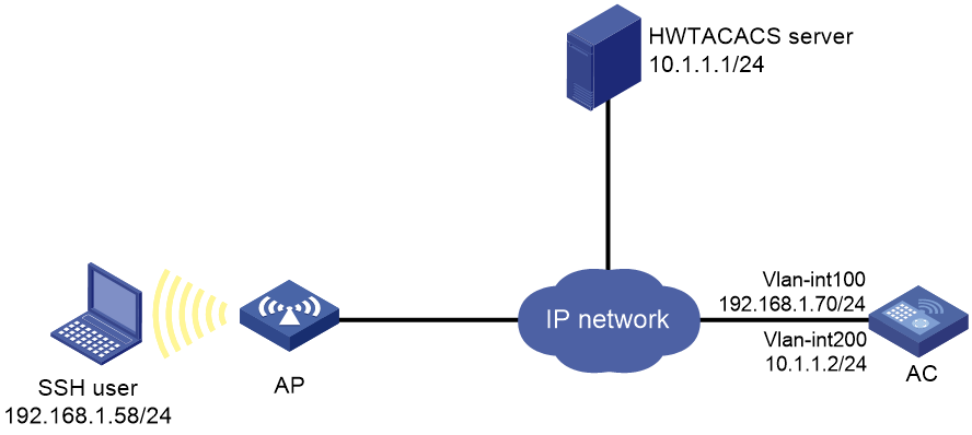
Configuring the HWTACACS server
# Set the shared keys to expert for secure communication with the AC. (Details not shown.)
# Add an account for the SSH user and specify the password. (Details not shown.)
Configuring the AC
# Configure IP addresses for the interfaces. (Details not shown.)
# Create an HWTACACS scheme.
<AC> system-view
[AC] hwtacacs scheme hwtac
# Specify the primary authentication server and the authentication port.
[AC-hwtacacs-hwtac] primary authentication 10.1.1.1 49
# Specify the primary authorization server and the authorization port.
[AC-hwtacacs-hwtac] primary authorization 10.1.1.1 49
# Specify the primary accounting server and the accounting port.
[AC-hwtacacs-hwtac] primary accounting 10.1.1.1 49
# Set the shared keys to expert in plaintext form for secure HWTACACS communication.
[AC-hwtacacs-hwtac] key authentication simple expert
[AC-hwtacacs-hwtac] key authorization simple expert
[AC-hwtacacs-hwtac] key accounting simple expert
# Exclude domain names from the usernames sent to the HWTACACS server.
[AC-hwtacacs-hwtac] user-name-format without-domain
[AC-hwtacacs-hwtac] quit
# Create an ISP domain named bbb and configure the domain to use the HWTACACS scheme for authentication, authorization, and accounting of login users.
[AC] domain bbb
[AC-isp-bbb] authentication login hwtacacs-scheme hwtac
[AC-isp-bbb] authorization login hwtacacs-scheme hwtac
[AC-isp-bbb] accounting login hwtacacs-scheme hwtac
[AC-isp-bbb] quit
# Specify ISP domain bbb as the default domain.
[AC] domain default enable bbb
# Create local RSA and DSA key pairs.
[AC] public-key local create rsa
[AC] public-key local create dsa
# Enable the Stelnet server.
[AC] ssh server enable
# Enable scheme authentication for user lines VTY 0 through VTY 31.
[AC] line vty 0 31
[AC-line-vty0-31] authentication-mode scheme
[AC-line-vty0-31] quit
# Enable the default user role feature to assign authenticated SSH users the default user role network-operator.
[AC] role default-role enable
Verifying the configuration
# Initiate an SSH connection to the AC, and enter the correct username and password. The user logs in to the AC. (Details not shown.)
# Verify that the user can use the commands permitted by the network-operator user role. (Details not shown.)
Example: Configuring local authentication, HWTACACS authorization, and RADIUS accounting for SSH users
Network configuration
As shown in Figure 12, configure the AC to meet the following requirements:
· Perform local authentication for SSH servers.
· Use the HWTACACS server and RADIUS server for SSH user authorization and accounting, respectively.
· Exclude domain names from the usernames sent to the servers.
· Assign the default user role network-operator to SSH users after they pass authentication.
Configure an account named hello for the SSH user. Configure the shared keys to expert for secure communication with the HWTACACS server and RADIUS server.
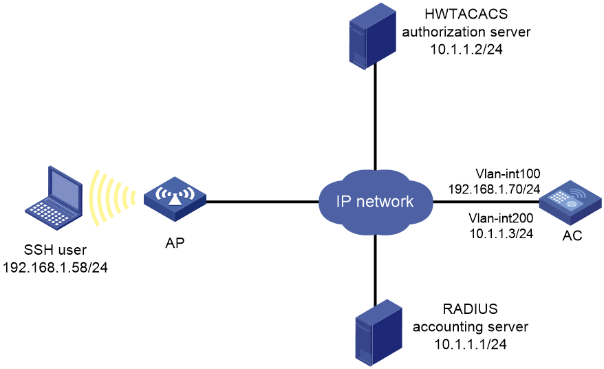
Configuring the HWTACACS server
# Set the shared keys to expert for secure communication with the AC, add an account for the SSH user, and specify the user password. (Details not shown.)
Configuring the RADIUS server
# Set the shared keys to expert for secure communication with the AC, add an account for the SSH user, and specify the user password. (Details not shown.)
Configuring the AC
# Configure IP addresses for interfaces. (Details not shown.)
# Create local RSA and DSA key pairs.
<AC> system-view
[AC] public-key local create rsa
[AC] public-key local create dsa
# Enable the Stelnet server.
[AC] ssh server enable
# Enable scheme authentication for user lines VTY 0 through VTY 31.
[AC] line vty 0 31
[AC-line-vty0-31] authentication-mode scheme
[AC-line-vty0-31] quit
# Configure an HWTACACS scheme.
[AC] hwtacacs scheme hwtac
[AC-hwtacacs-hwtac] primary authorization 10.1.1.2 49
[AC-hwtacacs-hwtac] key authorization simple expert
[AC-hwtacacs-hwtac] user-name-format without-domain
[AC-hwtacacs-hwtac] quit
# Configure a RADIUS scheme.
[AC] radius scheme rd
[AC-radius-rd] primary accounting 10.1.1.1 1813
[AC-radius-rd] key accounting simple expert
[AC-radius-rd] user-name-format without-domain
[AC-radius-rd] quit
# Create a device management user.
[AC] local-user hello class manage
# Assign the SSH service to the local user.
[AC-luser-manage-hello] service-type ssh
# Set the password to 123456TESTplat&! in plaintext form for the local user.
[AC-luser-manage-hello] password simple 123456TESTplat&!
[AC-luser-manage-hello] quit
# Create an ISP domain named bbb and configure the login users to use local authentication, HWTACACS authorization, and RADIUS accounting.
[AC] domain bbb
[AC-isp-bbb] authentication login local
[AC-isp-bbb] authorization login hwtacacs-scheme hwtac
[AC-isp-bbb] accounting login radius-scheme rd
[AC-isp-bbb] quit
# Specify ISP domain bbb as the default domain.
[AC] domain default enable bbb
# Enable the default user role feature to assign authenticated SSH users the default user role network-operator.
[AC] role default-role enable
Verifying the configuration
# Initiate an SSH connection to the AC, and enter username hello@bbb and the correct password. The user logs in to the AC. (Details not shown.)
# Verify that the user can use the commands permitted by the network-operator user role. (Details not shown.)
Example: Configuring authentication and authorization for SSH users by a RADIUS server
Network configuration
As shown in Figure 13, configure the AC to meet the following requirements:
· Use the RADIUS server for SSH user authentication and authorization.
· Include domain names in the usernames sent to the RADIUS server.
· Assign the network-admin user role to SSH users after they pass authentication.
The RADIUS server runs IMC PLAT 7.3 (E0605) and IMC UAM 7.3 (E0512). Add an account with username hello@bbb on the RADIUS server.
The RADIUS server and the AC use expert as the shared key for secure RADIUS communication. The ports for authentication and accounting are 1812 and 1813, respectively.

Configuring the RADIUS server
1. Add the AC to IMC UAM as an access device:
Log in to IMC, click the User tab, and select User Access Policy > Access Device Management > Access Device from the navigation tree. Then, click Add to configure an access device as follows:
a. Set the ports for authentication and accounting to 1812 and 1813, respectively.
b. Select Device Management Service from the Service Type list.
c. Select H3C (General) from the Access Device Type list.
d. Set the shared key to expert for secure RADIUS communication.
e. Select an access device from the device list or manually add an access device. In this example, the device IP address is 10.1.1.2.
f. Use the default values for other parameters and click OK.
The IP address of the access device specified here must be the same as the source IP address of the RADIUS packets sent from the AC. The source IP address is chosen in the following order on the AC:
¡ IP address specified by using the nas-ip command.
¡ IP address specified by using the radius nas-ip command.
¡ IP address of the outbound interface (the default).
Figure 14 Adding the AC as an access device
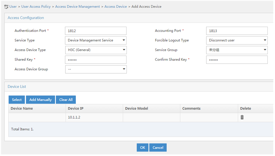
2. Add an account for device management:
Click the User tab, and select Device User > Device User from the navigation tree. Then, click Add to configure a device management account as follows:
a. Enter account name hello@bbb and specify the password.
b. Select SSH from the Login Type list.
c. Enter user role network-admin.
d. Specify 10.1.1.0 to 10.1.1.255 as the IP address range of the hosts to be managed.
e. Click OK.
|
|
NOTE: The IP address range must contain the IP address of the AC. |
Figure 15 Adding an account for device management
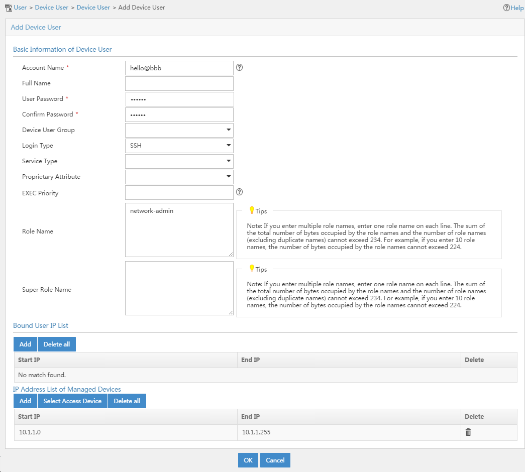
Configuring the AC
# Configure IP addresses for interfaces. (Details not shown.)
# Create local RSA and DSA key pairs.
<AC> system-view
[AC] public-key local create rsa
[AC] public-key local create dsa
# Enable the Stelnet server.
[AC] ssh server enable
# Enable scheme authentication for user lines VTY 0 through VTY 31.
[AC] line vty 0 31
[AC-line-vty0-31] authentication-mode scheme
[AC-line-vty0-31] quit
# Create a RADIUS scheme.
[AC] radius scheme rad
# Specify the primary authentication server and the authentication port.
[AC-radius-rad] primary authentication 10.1.1.1 1812
# Set the shared key to expert in plaintext form for secure communication with the server.
[AC-radius-rad] key authentication simple expert
# Include domain names in the usernames sent to the RADIUS server.
[AC-radius-rad] user-name-format with-domain
[AC-radius-rad] quit
# Create an ISP domain named bbb and configure authentication, authorization, and accounting methods for login users.
[AC] domain bbb
[AC-isp-bbb] authentication login radius-scheme rad
[AC-isp-bbb] authorization login radius-scheme rad
[AC-isp-bbb] accounting login none
[AC-isp-bbb] quit
# Specify ISP domain bbb as the default domain.
[AC] domain default enable bbb
Verifying the configuration
# Initiate an SSH connection to the AC, and enter username hello@bbb and the correct password. The user logs in to the AC. (Details not shown.)
# Verify that the user can use the commands permitted by the network-admin user role. (Details not shown.)
Example: Configuring authentication for SSH users by an LDAP server
Network configuration
As shown in Figure 16, the LDAP server uses domain ldap.com and runs Microsoft Windows 2003 Server Active Directory.
Configure the AC to meet the following requirements:
· Use the LDAP server to authenticate SSH users.
· Assign the level-0 user role to SSH users after they pass authentication.
On the LDAP server, set the administrator password to admin!123456, add user aaa, and set the user's password to ldap!123456.
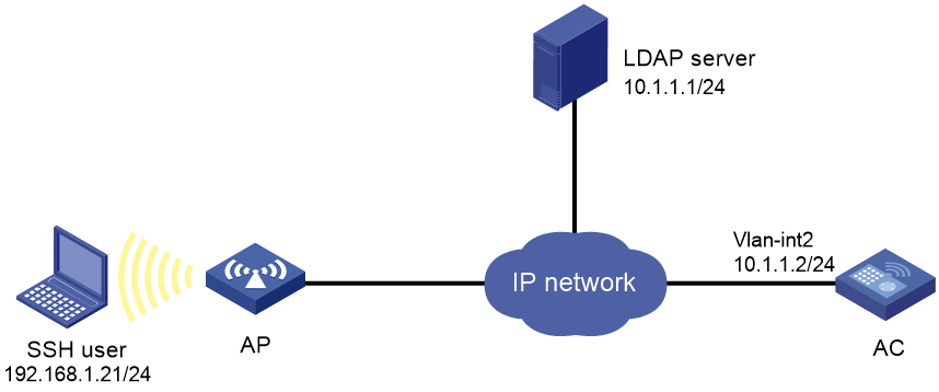
Configuring the LDAP server
1. Add a user named aaa and set the password to ldap!123456:
a. On the LDAP server, select Start > Control Panel > Administrative Tools.
b. Double-click Active Directory Users and Computers.
The Active Directory Users and Computers window is displayed.
c. From the navigation tree, click Users under the ldap.com node.
d. Select Action > New > User from the menu to display the dialog box for adding a user.
e. Enter logon name aaa and click Next.
Figure 17 Adding user aaa
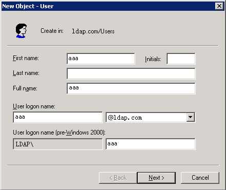
f. In the dialog box, enter password ldap!123456, select options as needed, and click Next.
Figure 18 Setting the user's password
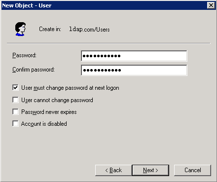
g. Click OK.
2. Add user aaa to group Users:
a. From the navigation tree, click Users under the ldap.com node.
b. In the right pane, right-click user aaa and select Properties.
c. In the dialog box, click the Member Of tab and click Add.
Figure 19 Modifying user properties
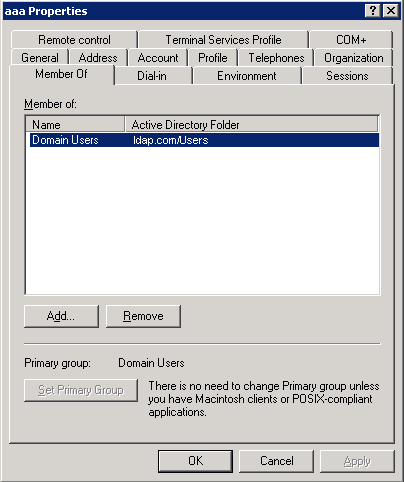
d. In the Select Groups dialog box, enter Users in the Enter the object names to select field, and click OK.
User aaa is added to group Users.
Figure 20 Adding user aaa to group Users
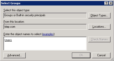
3. Set the administrator password to admin!123456:
a. In the right pane, right-click user Administrator and select Set Password.
b. In the dialog box, enter the administrator password. (Details not shown.)
Configuring the AC
# Configure the IP address of VLAN-interface 2 (the interface connected the AC to the LDAP server).
<AC> system-view
[AC] vlan 2
[AC-vlan2] quit
[AC] interface vlan-interface 2
[AC-Vlan-interface2] ip address 10.1.1.2 24
[AC-Vlan-interface2] quit
# Create local RSA and DSA key pairs.
[AC] public-key local create rsa
[AC] public-key local create dsa
# Enable the Stelnet server.
[AC] ssh server enable
# Enable scheme authentication for user lines VTY 0 through VTY 31.
[AC] line vty 0 31
[AC-line-vty0-31] authentication-mode scheme
[AC-line-vty0-31] quit
# Configure an LDAP server.
[AC] ldap server ldap1
# Specify the IP address of the LDAP authentication server.
[AC-ldap-server-ldap1] ip 10.1.1.1
# Specify the administrator DN.
[AC-ldap-server-ldap1] login-dn cn=administrator,cn=users,dc=ldap,dc=com
# Specify the administrator password.
[AC-ldap-server-ldap1] login-password simple admin!123456
# Configure the base DN for user search.
[AC-ldap-server-ldap1] search-base-dn dc=ldap,dc=com
[AC-ldap-server-ldap1] quit
# Create an LDAP scheme.
[AC] ldap scheme ldap-shm1
# Specify the LDAP authentication server.
[AC-ldap-ldap-shm1] authentication-server ldap1
[AC-ldap-ldap-shm1] quit
# Create an ISP domain named bbb and configure authentication, authorization, and accounting methods for login users.
[AC] domain bbb
[AC-isp-bbb] authentication login ldap-scheme ldap-shm1
[AC-isp-bbb] authorization login none
[AC-isp-bbb] accounting login none
[AC-isp-bbb] quit
# Specify ISP domain bbb as the default domain.
[AC] domain default enable bbb
Verifying the configuration
# Initiate an SSH connection to the AC, and enter username aaa@bbb and password ldap!123456. The user logs in to the AC. (Details not shown.)
# Verify that the user can use the commands permitted by the level-0 user role. (Details not shown.)
Example: Configuring AAA for 802.1X users by a RADIUS server
Network configuration
As shown in Figure 21, configure the AC to meet the following requirements:
· Use the RADIUS server for authentication, authorization, and accounting of 802.1X users.
· Include domain names in the usernames sent to the RADIUS server.
In this example, the RADIUS server runs IMC PLAT 7.1 (E0303), IMC UAM 7.1 (E0304), and IMC CAMS 7.1 (E0301). On the RADIUS server, perform the following tasks:
· Add a service that charges 120 dollars for up to 120 hours per month and assigns authenticated users to VLAN 4.
· Configure a user account named dot1x@bbb and assign the service to the user.
Set the shared keys to expert for secure RADIUS communication. Set the ports for authentication and accounting to 1812 and 1813, respectively.
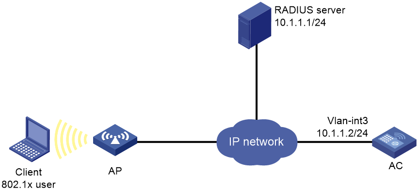
Configuring the RADIUS server
1. Add the AC to IMC UAM as an access device:
Log in to IMC, click the User tab, and select User Access Policy > Access Device Management > Access Device from the navigation tree. Then, click Add to configure an access device as follows:
a. Set the ports for authentication and accounting to 1812 and 1813, respectively.
b. Select LAN Access Service from the Service Type list.
c. Select H3C(General) from the Access Device Type list.
d. Set the shared key to expert for secure authentication and accounting communication.
e. Select an access device from the device list or manually add an access device. In this example, the device IP address is 10.1.1.2.
f. Use the default values for other parameters.
g. Click OK.
The IP address of the access device specified here must be the same as the source IP address of the RADIUS packets sent from the AC. The source IP address is chosen in the following order on the AC:
¡ IP address specified by using the nas-ip command.
¡ IP address specified by using the radius nas-ip command.
¡ IP address of the outbound interface (the default).
Figure 22 Adding the AC as an access device
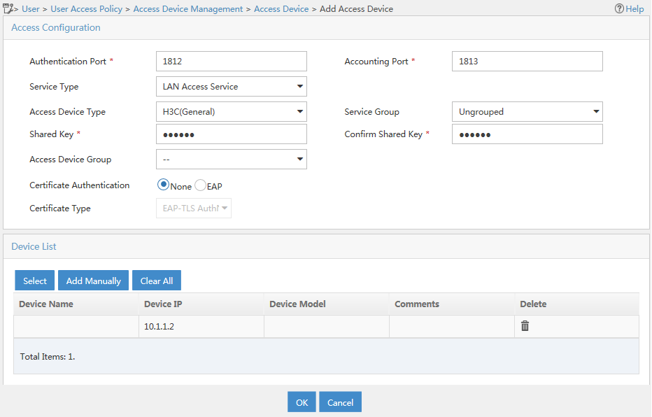
2. Add a charging plan:
Click the User tab, and select Accounting Manager > Charging Plans from the navigation tree to enter the charging plan configuration page. Then, click Add to configure a charging plan as follows:
a. Add a plan named UserAcct.
b. Select Flat rate from the Charging Template list.
c. Select time for Charge Based on, select Monthly for Billing Term, and enter 120 in the Fixed Fee field.
d. Enter 120 in the Usage Threshold field and select hr (hours) for the in field. The configuration allows the user to access the Internet for up to 120 hours per month.
e. Use the default values for other parameters.
f. Click OK.
Figure 23 Adding a charging plan
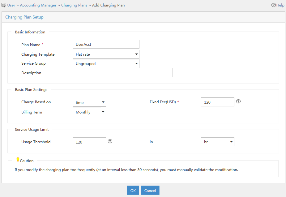
3. Add an access policy:
Click the User tab, and select User Access Policy > Access Policy from the navigation tree. Then, click Add to configure an access policy as follows:
a. Enter access policy name Dot1x auth.
b. Set the ID of the VLAN to be deployed to 4.
c. Configure other parameters as needed.
d. Click OK.
Figure 24 Adding an access policy
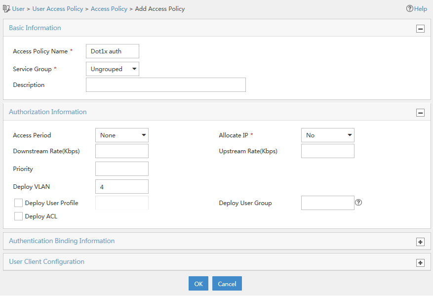
4. Add an access service:
Click the User tab, and select User Access Policy > Access Service from the navigation tree. Then, click Add to configure a service as follows:
a. Add a service named Dot1x Service, and set the service suffix to bbb, the authentication domain for the 802.1X user. With the service suffix configured, you must configure the access device to send usernames that include domain names to the RADIUS server.
b. Select UserAcct from the Charging Plan list.
c. Select Dot1x auth from the Default Access Policy list.
d. Configure other parameters as needed.
e. Click OK.
Figure 25 Adding a service
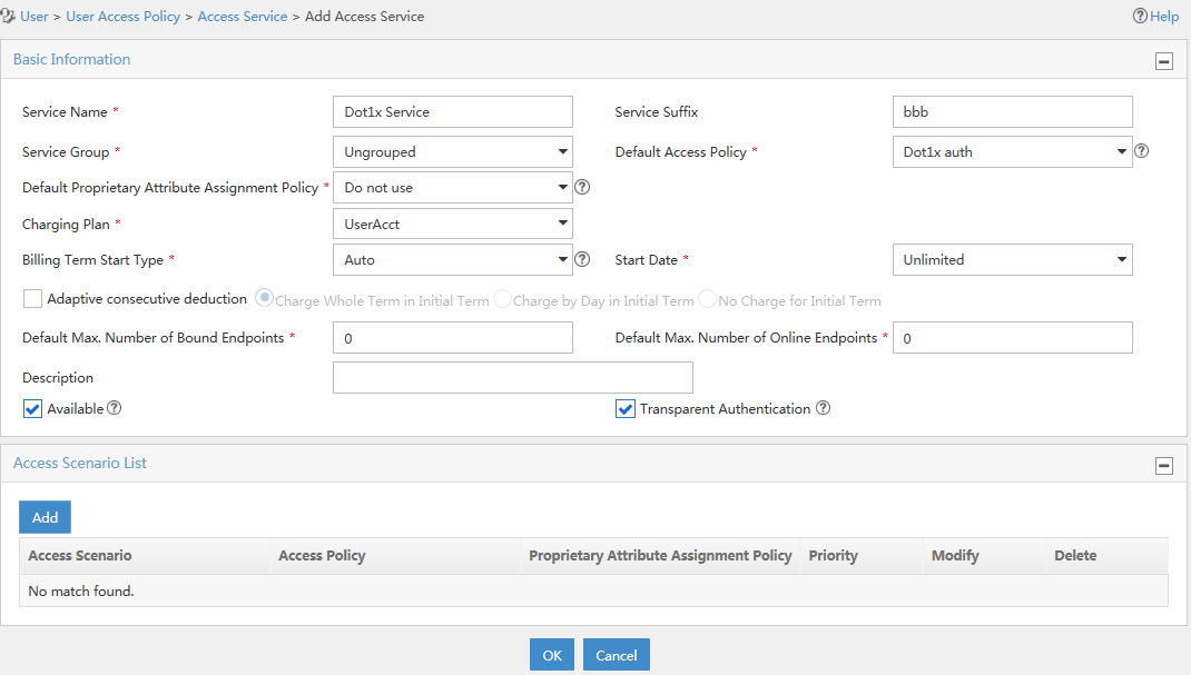
5. Add an access user:
Click the User tab, and select All Access Users from the navigation tree to enter the All Access Users page. Then, click Add to configure a user as follows:
a. Select user test or manually add a user named test.
b. Specify the account name as dot1x and configure the password.
c. Select Dot1x Service in the Access Service area.
d. Configure other parameters as needed.
e. Click OK.
Figure 26 Adding an access user account
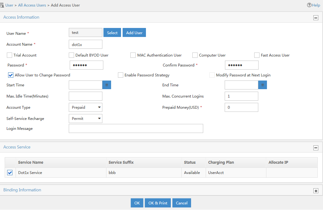
Configuring the AC
1. Configure a RADIUS scheme:
# Create a RADIUS scheme named rad and enter RADIUS scheme view.
<AC> system-view
[AC] radius scheme rad
# Specify the primary authentication server and primary accounting server, and configure the keys for communication with the servers.
[AC-radius-rad] primary authentication 10.1.1.1
[AC-radius-rad] primary accounting 10.1.1.1
[AC-radius-rad] key authentication simple expert
[AC-radius-rad] key accounting simple expert
# Include domain names in the usernames sent to the RADIUS server.
[AC-radius-rad] user-name-format with-domain
[AC-radius-rad] quit
2. Configure an authentication domain:
# Create an ISP domain named bbb and enter ISP domain view.
[AC] domain bbb
# Configure the ISP domain to use RADIUS scheme rad for authentication, authorization, and accounting of LAN users.
[AC-isp-bbb] authentication lan-access radius-scheme rad
[AC-isp-bbb] authorization lan-access radius-scheme rad
[AC-isp-bbb] accounting lan-access radius-scheme rad
[AC-isp-bbb] quit
3. Configure 802.1X authentication:
# Enable port security globally.
[AC] port-security enable
# Enable 802.1X EAP relay.
[AC] dot1x authentication-method eap
# Configure service template 1.
[AC] wlan service-template 1
# Set the SSID to sectest.
[AC-wlan-st-1] ssid sectest
# Bind VLAN 2 to the service template.
[AC-wlan-st-1] vlan 2
# Set the AKM mode to 802.1X.
[AC-wlan-st-1] akm mode dot1x
# Set the authentication mode to 802.1X.
[AC-wlan-st-1] client-security authentication-mode dot1x
# Specify the TKIP cipher suite, and enable the WPA IE in beacon and probe responses.
[AC-wlan-st-1] cipher-suite tkip
[AC-wlan-st-1] security-ie wpa
# Specify ISP domain bbb as the 802.1X authentication domain.
[AC-wlan-st-1] dot1x domain bbb
# Enable the service template.
[AC-wlan-st-1] service-template enable
[AC-wlan-st-1] quit
# Create a manual AP named ap1, and specify the AP model and serial number.
[AC] wlan ap ap1 model WA6320
[AC-wlan-ap-ap1] serial-id 210235A29G007C000020
# Bind the service template to radio 1 of the AP.
[AC-wlan-ap-ap1] radio 1
[AC-wlan-ap-ap1-radio-1] type dot11an
[AC-wlan-ap-ap1-radio-1] service-template 1
[AC-wlan-ap-ap1-radio-1] radio enable
[AC-wlan-ap-ap1-radio-1] quit
[AC-wlan-ap-ap1] quit
Verifying the configuration
1. On the host, use account dot1x@bbb to pass 802.1X authentication:
# If the host runs the Windows XP 802.1X client, configure the network connection properties as follows:
a. Click the Authentication tab of the properties window.
b. Select the Enable IEEE 802.1X authentication for this network option.
c. Select PEAP as the EAP type.
d. Click OK.
The user passes authentication after entering the correct username and password on the authentication page.
# If the host runs the iNode client, no advanced authentication options are required. The user can pass authentication after entering username dot1x@bbb and the correct password on the client property page.
|
|
IMPORTANT: Make sure the client can update its IP address to access the resources in the authorized VLAN after passing authentication. |
2. On the AC, verify that the server assigns the port connecting the client to VLAN 4 after the user passes authentication. (Details not shown.)
3. Display 802.1X connection information on the AC.
[AC] display dot1x connection
Example: Configuring and managing a local guest
Network configuration
As shown in Figure 27, create a local guest named user1 for Jack. Configure local guest attributes and manage the local guest on the AC as follows:
· Configure attributes for the local guest, including the password, user group, validity period, and sponsor information.
· Enable the guest auto-delete feature.
· Specify an SMTP server and email sender address for the device to send local guest email notifications.
· Configure email addresses for the local guest, guest sponsor, and guest manager.
· Configure the subject and body of the email notifications to be sent to the guest, guest sponsor, and guest manager.
· Send email notifications of the local guest account information to the guest and guest sponsor.

Procedure
1. Configure 802.1X settings. Make sure the guest can pass 802.1X authentication to access the network. (Details not shown.)
2. Manage local guests:
# Enable the guest auto-delete feature for expired local guests.
<AC> system-view
[AC] local-guest auto-delete enable
# Specify an SMTP server to send local guest email notifications.
[AC] local-guest email smtp-server smtp://192.168.0.112/smtp
# Specify the email sender address as [email protected] in the email notifications sent by the device for local guests.
[AC] local-guest email sender [email protected]
# Specify the email address of the guest manager as mailto:[email protected].
[AC] local-guest manager-email mailto:[email protected]
# Configure the subject and body of the email notifications to be sent to the local guest.
[AC] local-guest email format to guest subject Guest account information
[AC] local-guest email format to guest body A guest account has been created for your use. The username, password, and valid dates for the account are given below.
# Configure the subject and body of the email notifications to be sent to the guest sponsor.
[AC] local-guest email format to sponsor subject Guest account information
[AC] local-guest email format to sponsor body A guest account has been created for your use. The username, password, and valid dates for the account are given below.
# Configure the subject and body of the email notifications to be sent to the guest manager.
[AC] local-guest email format to manager subject Guest register information
[AC] local-guest email format to manager body A guest account has been registered. The username for the account is given below. Please approve the register information.
3. Configure the local guest:
# Create a user group named guest1.
[AC] user-group guest1
[AC-ugroup-guest1] quit
# Create a local guest named user1 and enter local guest view.
[AC] local-user user1 class network guest
# Set the guest password to 123456 in plaintext form.
[AC-luser-network(guest)-user1] password simple 123456
# Assign the guest to user group guest1.
[AC-luser-network(guest)-user1] group guest1
# Specify the name of the local guest.
[AC-luser-network(guest)-user1] fullname Jack
# Specify the company of the local guest.
[AC-luser-network(guest)-user1] company cc
# Configure the email address of the local guest.
[AC-luser-network(guest)-user1] email [email protected]
# Configure the phone number of the local guest.
[AC-luser-network(guest)-user1] phone 131129237
# Configure a description for the local guest.
[AC-luser-network(guest)-user1] description A guest from company cc
# Configure the validity period of the local guest.
[AC-luser-network(guest)-user1] validity-datetime 2015/4/1 08:00:00 to 2015/4/3 18:00:00
# Specify the guest sponsor name as Sam.
[AC-luser-network(guest)-user1] sponsor-full-name Sam
# Configure the email address of the guest sponsor.
[AC-luser-network(guest)-user1] sponsor-email [email protected]
# Configure the department of the guest sponsor as security.
[AC-luser-network(guest)-user1] sponsor-department security
[AC-luser-network(guest)-user1] quit
[AC] quit
4. Configure the device to send guest email notifications:
# Send an email notification to the guest sponsor.
<AC> local-guest send-email user-name user1 to sponsor
# Send an email notification to the guest.
<AC> local-guest send-email user-name user1 to guest
Verifying the configuration
# Display local guest information.
<AC> display local-user user1 class network guest
Network access guest user user1:
State: Active
Service type: LAN access/Portal
User group: guest1
Full name: Jack
Company: cc
Email: [email protected]
Phone: 131129237
Description: A guest from company cc
Sponsor full name: Sam
Sponsor department: security
Sponsor email: [email protected]
Period of validity:
Start date and time: 2015/04/01-08:00:00
Expiration date and time:2015/04/03-18:00:00
# Verify that Jack can use username user1 and password 123456 to pass local authentication and come online during the validity period. (Details not shown.)
Example: Configuring AAA and local BYOD authorization for portal users
Network configuration
As shown in Figure 28:
· The AP forwards data traffic for the client.
· The client obtains a public IP address through DHCP for authentication.
· A portal server provides portal authentication and portal Web services.
· The access device performs local authentication, authorization, and accounting for users.
· The client runs Windows 8 and can access network resources in VLAN 3 after passing the user authentication.
Configure direct portal authentication, so the client can access only the portal server before passing the authentication and can access other network resources after passing the authentication.
In this example, the portal server runs IMC PLAT 7.1 (E0303) and IMC UAM 7.1 (E0304).

Configuring the portal server
1. Configure the portal server:
a. Log into IMC.
b. Click the Service tab.
c. From the navigation tree, select User Access Policy > Portal Service > Server.
d. On the Server page, configure the portal server parameters as needed.
This example uses the default values for the parameters, as shown in Figure 29.
Figure 29 Portal server configuration
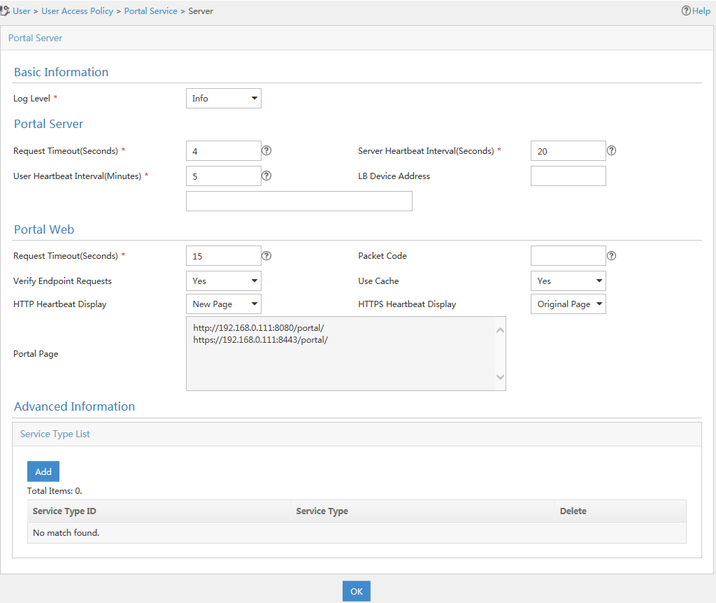
e. Click OK.
2. Configure the IP address group:
a. From the navigation tree, select User Access Policy > Portal Service > IP Group.
b. Click Add.
c. On the Add IP Group page, configure the following parameters, as shown in Figure 30:
- Enter a name in the IP Group Name field.
- Enter the start IP address and the end IP address of the IP group.
Make sure the client IP address is in the IP address range.
- Select a service group from the Service Group list.
This example uses the default value Ungrouped.
- Select Normal from the Action list.
Figure 30 Adding an IP address group
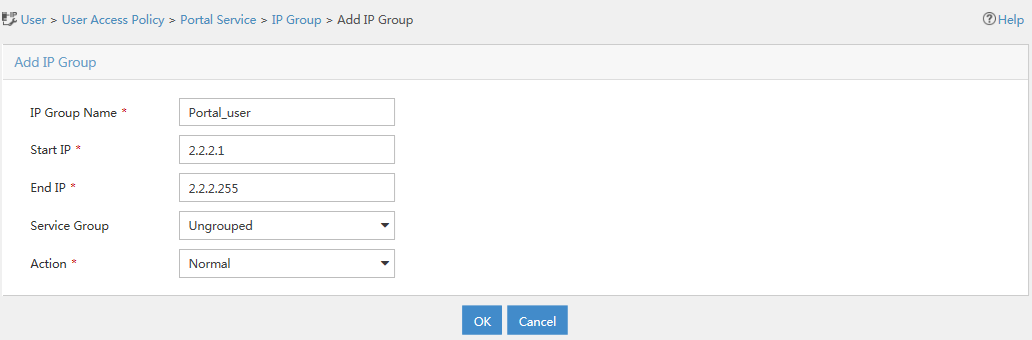
d. Click OK.
3. Add a portal device:
a. From the navigation tree, select User Access Policy > Portal Service > Device.
b. Click Add.
c. On the Add Device page, configure the following parameters, as shown in Figure 31:
- Enter a name in the Device Name field. This example uses NAS.
- Enter the IP address of the AC's VLAN interface connected to the client in the IP Address field.
- Enter a key in the Key field.
Make sure the key is the same as the key configured on the AC.
- Select an access method from the Access Method list.
This example uses direct portal authentication and must select Directly Connected.
- Use the default values for other parameters.
Figure 31 Adding a portal device
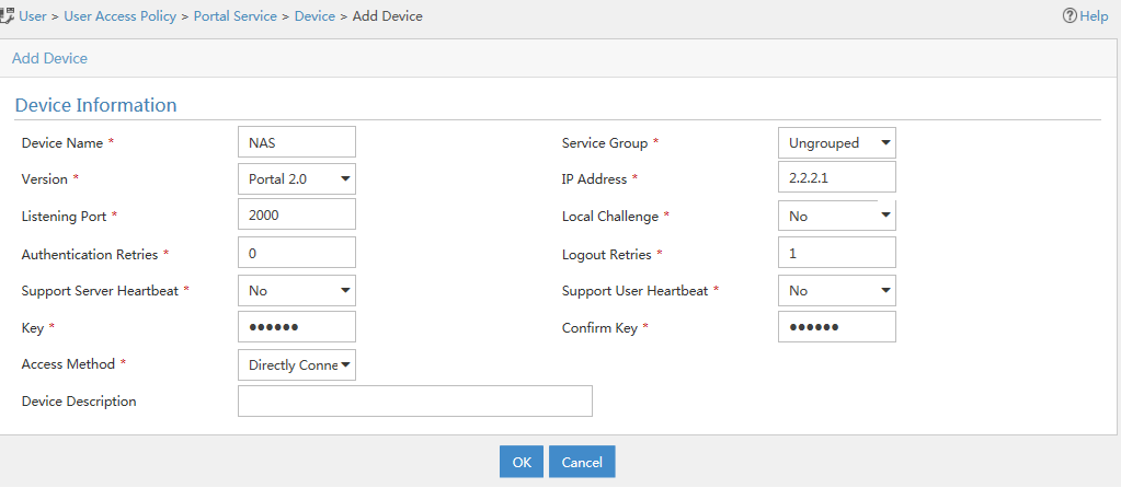
d. Click OK.
4. Associate the portal device with the IP group:
a. On the Device page,
click the ![]() icon in the Operation column of the device named NAS, as shown in Figure 32.
icon in the Operation column of the device named NAS, as shown in Figure 32.
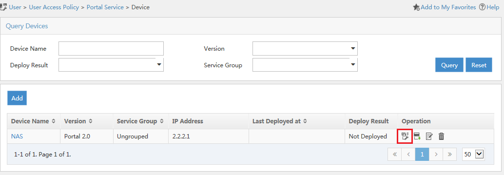
a. On the Configure Portal Group page, click Add.
b. On the Add Portal Group page, configure the following parameters, as shown in Figure 33:
- Enter a name in the Port Group Name field.
- Select CHAP from the Authentication Type list.
- Select the configured IP group from the IP Group list.
The IP address used by the user to access the network must be within this IP group.
- Use the default values for other parameters.
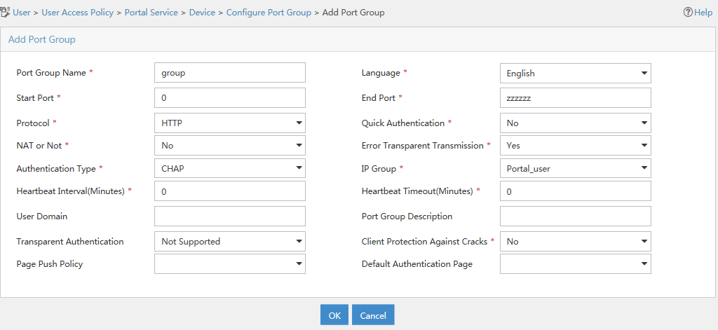
d. Click OK.
Configuring the AC
1. Configure the authentication domain:
# Create an ISP domain named bbb and enter ISP domain view.
<AC> system-view
[AC] domain bbb
# Configure local authentication, authorization, and accounting for portal users in ISP domain bbb.
[AC-isp-bbb] authentication portal local
[AC-isp-bbb] authorization portal local
[AC-isp-bbb] accounting portal local
[AC-isp-bbb] quit
# Specify ISP domain bbb as the default domain.
[AC] domain default enable bbb
2. Configure portal authentication:
# Configure the portal authentication server.
[AC] portal server newpt
[AC-portal-server-newpt] ip 192.168.0.111 key simple portal
[AC-portal-server-newpt] port 50100
[AC-portal-server-newpt] quit
# Specify the portal Web server at http://192.168.0.111:8080/portal.
[AC] portal web-server newpt
[AC-portal-websvr-newpt] url http://192.168.0.111:8080/portal
[AC-portal-websvr-newpt] quit
# Enable direct portal authentication on VLAN-interface 2.
[AC] interface vlan-interface 2
[AC–Vlan-interface2] portal enable method direct
# Specify portal Web server newpt on VLAN-interface 2.
[AC–Vlan-interface2] portal apply web-server newpt
[AC–Vlan-interface2] quit
# Specify portal Web server newpt on service template newst.
[AC] wlan service-template newst
[AC–wlan-st-newst] portal apply web-server newpt
# Set the BAS IP to 192.168.0.110 for the portal packets sent to the portal authentication server.
[AC–wlan-st-newst] portal bas-ip 192.168.0.110
# Configure APs to forward client data traffic.
[AC–wlan-st-newst] client forwarding-location ap
# Enable service template newst.
[AC–wlan-st-newst] service-template enable
[AC–wlan-st-newst] quit
3. Configure local BYOD authorization:
# Specify VLAN 3 as the authorization VLAN for BYOD users of the Microsoft Windows 8 endpoint type in user group windows8.
[AC] user-group windows8
[AC-ugroup-windows8] byod authorization device-type "Microsoft Windows 8" vlan 3
[AC-ugroup-windows8] quit
# Configure a BYOD endpoint identification rule.
[AC] byod rule dhcp-option 1,15,3,6,44,46,47,31,33,121,249,252,43.33 device-type "Microsoft Windows 8"
4. Configure a local user:
# Create a network access user named user1 and enter local user view.
[AC] local-user user1 class network
# Specify the service type as portal.
[AC-luser-network-user1] service-type portal
# Set the user password to 123456TESTplat&! in plain text.
[AC-luser-network-user1] password simple 123456TESTplat&!
# Assign user user1 to user group windows8.
[AC-luser-network-user1] group windows8
[AC-luser-network-user1] quit
Verifying the configuration
# Display portal configuration.
[AC] display portal interface vlan-interface 100
# Display BYOD endpoint identification rules.
[AC] display byod rule
# Display BYOD endpoint type-specific authorization attributes in user group windows8.
[AC] display user-group name windows8 byod-authorization
# Verify that the Microsoft Windows 8 portal user can access only http://192.168.0.111:8080/portal for authentication before it passes portal authentication. (Details not shown.)
# Verify that the Microsoft Windows 8 portal user can access the network resources in VLAN 3 after it passes authentication. (Details not shown.)
# Display online portal user information.
[AC] display portal user interface vlan-interface 100
Troubleshooting AAA
RADIUS authentication failure
Symptom
User authentication always fails.
Analysis
Possible reasons include:
· A communication failure exists between the NAS and the RADIUS server.
· The username is not in the userid@isp-name format, or the ISP domain is not correctly configured on the NAS.
· The user is not configured on the RADIUS server.
· The password entered by the user is incorrect.
· The RADIUS server and the NAS are configured with different shared keys.
Solution
To resolve the problem:
1. Verify the following items:
¡ The NAS and the RADIUS server can ping each other.
¡ The username is in the userid@isp-name format and the ISP domain is correctly configured on the NAS.
¡ The user is configured on the RADIUS server.
¡ The correct password is entered.
¡ The same shared key is configured on both the RADIUS server and the NAS.
2. If the problem persists, contact H3C Support.
RADIUS packet delivery failure
Symptom
RADIUS packets cannot reach the RADIUS server.
Analysis
Possible reasons include:
· A communication failure exists between the NAS and the RADIUS server.
· The NAS is not configured with the IP address of the RADIUS server.
· The authentication and accounting UDP ports configured on the NAS are incorrect.
· The RADIUS server's authentication and accounting port numbers are being used by other applications.
Solution
To resolve the problem:
1. Verify the following items:
¡ The link between the NAS and the RADIUS server works well at both the physical and data link layers.
¡ The IP address of the RADIUS server is correctly configured on the NAS.
¡ The authentication and accounting UDP port numbers configured on the NAS are the same as those of the RADIUS server.
¡ The RADIUS server's authentication and accounting port numbers are available.
2. If the problem persists, contact H3C Support.
RADIUS accounting error
Symptom
A user is authenticated and authorized, but accounting for the user is not normal.
Analysis
The accounting server configuration on the NAS is not correct. Possible reasons include:
· The accounting port number configured on the NAS is incorrect.
· The accounting server IP address configured on the NAS is incorrect. For example, the NAS is configured to use a single server to provide authentication, authorization, and accounting services, but in fact the services are provided by different servers.
Solution
To resolve the problem:
1. Verify the following items:
¡ The accounting port number is correctly configured.
¡ The accounting server IP address is correctly configured on the NAS.
2. If the problem persists, contact H3C Support.
Troubleshooting HWTACACS
Similar to RADIUS troubleshooting. See "RADIUS authentication failure," "RADIUS packet delivery failure," and "RADIUS accounting error."
LDAP authentication failure
Symptom
User authentication fails.
Analysis
Possible reasons include:
· A communication failure exists between the NAS and the LDAP server.
· The LDAP server IP address or port number configured on the NAS is not correct.
· The username is not in the userid@isp-name format, or the ISP domain is not correctly configured on the NAS.
· The user is not configured on the LDAP server.
· The password entered by the user is incorrect.
· The administrator DN or password is not configured.
· Some user attributes (for example, the username attribute) configured on the NAS are not consistent with those configured on the server.
· No user search base DN is specified for the LDAP scheme.
Solution
To resolve the problem:
1. Verify the following items:
¡ The NAS and the LDAP server can ping each other.
¡ The IP address and port number of the LDAP server configured on the NAS match those of the server.
¡ The username is in the correct format and the ISP domain for the user authentication is correctly configured on the NAS.
¡ The user is configured on the LDAP server.
¡ The correct password is entered.
¡ The administrator DN and the administrator password are correctly configured.
¡ The user attributes (for example, the username attribute) configured on the NAS are consistent with those configured on the LDAP server.
¡ The user search base DN for authentication is specified.
2. If the problem persists, contact H3C Support.
Appendixes
Appendix A Commonly used RADIUS attributes
Commonly used RADIUS attributes are defined in RFC 2865, RFC 2866, RFC 2867, and RFC 2868.
Table 3 Commonly used RADIUS attributes
|
No. |
Attribute |
No. |
Attribute |
|
1 |
User-Name |
45 |
Acct-Authentic |
|
2 |
User-Password |
46 |
Acct-Session-Time |
|
3 |
CHAP-Password |
47 |
Acct-Input-Packets |
|
4 |
NAS-IP-Address |
48 |
Acct-Output-Packets |
|
5 |
NAS-Port |
49 |
Acct-Terminate-Cause |
|
6 |
Service-Type |
50 |
Acct-Multi-Session-Id |
|
7 |
Framed-Protocol |
51 |
Acct-Link-Count |
|
8 |
Framed-IP-Address |
52 |
Acct-Input-Gigawords |
|
9 |
Framed-IP-Netmask |
53 |
Acct-Output-Gigawords |
|
10 |
Framed-Routing |
54 |
(unassigned) |
|
11 |
Filter-ID |
55 |
Event-Timestamp |
|
12 |
Framed-MTU |
56-59 |
(unassigned) |
|
13 |
Framed-Compression |
60 |
CHAP-Challenge |
|
14 |
Login-IP-Host |
61 |
NAS-Port-Type |
|
15 |
Login-Service |
62 |
Port-Limit |
|
16 |
Login-TCP-Port |
63 |
Login-LAT-Port |
|
17 |
(unassigned) |
64 |
Tunnel-Type |
|
18 |
Reply-Message |
65 |
Tunnel-Medium-Type |
|
19 |
Callback-Number |
66 |
Tunnel-Client-Endpoint |
|
20 |
Callback-ID |
67 |
Tunnel-Server-Endpoint |
|
21 |
(unassigned) |
68 |
Acct-Tunnel-Connection |
|
22 |
Framed-Route |
69 |
Tunnel-Password |
|
23 |
Framed-IPX-Network |
70 |
ARAP-Password |
|
24 |
State |
71 |
ARAP-Features |
|
25 |
Class |
72 |
ARAP-Zone-Access |
|
26 |
Vendor-Specific |
73 |
ARAP-Security |
|
27 |
Session-Timeout |
74 |
ARAP-Security-Data |
|
28 |
Idle-Timeout |
75 |
Password-Retry |
|
29 |
Termination-Action |
76 |
Prompt |
|
30 |
Called-Station-Id |
77 |
Connect-Info |
|
31 |
Calling-Station-Id |
78 |
Configuration-Token |
|
32 |
NAS-Identifier |
79 |
EAP-Message |
|
33 |
Proxy-State |
80 |
Message-Authenticator |
|
34 |
Login-LAT-Service |
81 |
Tunnel-Private-Group-ID |
|
35 |
Login-LAT-Node |
82 |
Tunnel-Assignment-id |
|
36 |
Login-LAT-Group |
83 |
Tunnel-Preference |
|
37 |
Framed-AppleTalk-Link |
84 |
ARAP-Challenge-Response |
|
38 |
Framed-AppleTalk-Network |
85 |
Acct-Interim-Interval |
|
39 |
Framed-AppleTalk-Zone |
86 |
Acct-Tunnel-Packets-Lost |
|
40 |
Acct-Status-Type |
87 |
NAS-Port-Id |
|
41 |
Acct-Delay-Time |
88 |
Framed-Pool |
|
42 |
Acct-Input-Octets |
89 |
(unassigned) |
|
43 |
Acct-Output-Octets |
90 |
Tunnel-Client-Auth-id |
|
44 |
Acct-Session-Id |
91 |
Tunnel-Server-Auth-id |
Appendix B Descriptions for commonly used standard RADIUS attributes
|
No. |
Attribute |
Description |
|
1 |
User-Name |
Name of the user to be authenticated. |
|
2 |
User-Password |
User password for PAP authentication, only present in Access-Request packets when PAP authentication is used. |
|
3 |
CHAP-Password |
Digest of the user password for CHAP authentication, only present in Access-Request packets when CHAP authentication is used. |
|
4 |
NAS-IP-Address |
IP address for the server to use to identify the client. Typically, a client is identified by the IP address of its access interface. This attribute is only present in Access-Request packets. |
|
5 |
NAS-Port |
Physical port of the NAS that the user accesses. |
|
6 |
Service-Type |
Type of service that the user has requested or type of service to be provided. |
|
7 |
Framed-Protocol |
Encapsulation protocol for framed access. |
|
8 |
Framed-IP-Address |
IP address assigned to the user. |
|
11 |
Filter-ID |
Name of the filter list. This attribute is parsed as follows: · If the name is a string of all digits, it indicates an ACL number. · If the name is a string in the format of user-group=name1;name2;..;namex, it indicates a list of user group names. This type of filter list is applicable only to SSL VPN users. · If the name is not a string of all digits and the name string does not contain an equal sign (=), it indicates a user profile name. |
|
12 |
Framed-MTU |
MTU for the data link between the user and NAS. For example, this attribute can be used to define the maximum size of EAP packets allowed to be processed in 802.1X EAP authentication. |
|
14 |
Login-IP-Host |
IP address of the NAS interface that the user accesses. |
|
15 |
Login-Service |
Type of service that the user uses for login. |
|
18 |
Reply-Message |
Text to be displayed to the user, which can be used by the server to communicate information, for example, the cause of the authentication failure. |
|
26 |
Vendor-Specific |
Vendor-specific proprietary attribute. A packet can contain one or more proprietary attributes, each of which can contain one or more subattributes. |
|
27 |
Session-Timeout |
Maximum service duration for the user before termination of the session. |
|
28 |
Idle-Timeout |
Maximum idle time permitted for the user before termination of the session. |
|
31 |
Calling-Station-Id |
User identification that the NAS sends to the server. For the LAN access service provided by an H3C device, this attribute includes the MAC address of the user. |
|
32 |
NAS-Identifier |
Identification that the NAS uses to identify itself to the RADIUS server. |
|
40 |
Acct-Status-Type |
Type of the Accounting-Request packet. Possible values include: · 1—Start. · 2—Stop. · 3—Interim-Update. · 4—Reset-Charge. · 7—Accounting-On. (Defined in the 3rd Generation Partnership Project.) · 8—Accounting-Off. (Defined in the 3rd Generation Partnership Project.) · 9 to 14—Reserved for tunnel accounting. · 15—Reserved for failed. |
|
45 |
Acct-Authentic |
Authentication method used by the user. Possible values include: · 1—RADIUS. · 2—Local. · 3—Remote. |
|
60 |
CHAP-Challenge |
CHAP challenge generated by the NAS for MD5 calculation during CHAP authentication. |
|
61 |
NAS-Port-Type |
Type of the physical port of the NAS that is authenticating the user. Possible values include: · 15—Ethernet. · 16—Any type of ADSL. · 17—Cable. (With cable for cable TV.) · 19—WLAN-IEEE 802.11. · 201—VLAN. · 202—ATM. If the port is an ATM or Ethernet one and VLANs are implemented on it, the value of this attribute is 201. |
|
64 |
Tunnel-Type |
Tunneling protocols used. The value 13 represents VLAN. If the value is 13, the device interprets the Tunnel-Type, Tunnel-Medium-Type, and Tunnel-Private-Group-ID attributes as attributes to assign VLANs. |
|
65 |
Tunnel-Medium-Type |
Transport medium type to use for creating a tunnel. For VLAN assignment, the value must be 6 to indicate the 802 media plus Ethernet. |
|
79 |
EAP-Message |
Used to encapsulate EAP packets to allow RADIUS to support EAP authentication. |
|
80 |
Message-Authenticator |
Used for authentication and verification of authentication packets to prevent spoofing Access-Requests. This attribute is present when EAP authentication is used. |
|
81 |
Tunnel-Private-Group-ID |
Group ID for a tunnel session. To assign VLANs, the NAS conveys VLAN IDs by using this attribute. |
|
87 |
NAS-Port-Id |
String for describing the port of the NAS that is authenticating the user. |
Appendix C RADIUS subattributes (vendor ID 25506)
Table 4 lists all RADIUS subattributes with a vendor ID of 25506. Support for these subattributes depends on the device model.
Table 4 RADIUS subattributes (vendor ID 25506)
|
No. |
Subattribute |
Description |
|
1 |
Input-Peak-Rate |
Peak rate in the direction from the user to the NAS, in bps. |
|
2 |
Input-Average-Rate |
Average rate in the direction from the user to the NAS, in bps. |
|
3 |
Input-Basic-Rate |
Basic rate in the direction from the user to the NAS, in bps. |
|
4 |
Output-Peak-Rate |
Peak rate in the direction from the NAS to the user, in bps. |
|
5 |
Output-Average-Rate |
Average rate in the direction from the NAS to the user, in bps. |
|
6 |
Output-Basic-Rate |
Basic rate in the direction from the NAS to the user, in bps. |
|
15 |
Remanent_Volume |
Total amount of data available for the connection, in different units for different server types. |
|
17 |
ISP-ID |
ISP domain where the user obtains authorization information. |
|
20 |
Command |
Operation for the session, used for session control. Possible values include: · 1—Trigger-Request. · 2—Terminate-Request. · 3—SetPolicy. · 4—Result. · 5—PortalClear. |
|
21 |
ACL-Version |
IP protocol version for an ACL. This attribute is used with the Filter-ID attribute to identify the IP protocol version of the ACL in the filter list. · 1—IPv4. · 2—IPv6. |
|
24 |
Control_Identifier |
Identifier for a packet that is resent by the server. For packets resent by the server during the same session, the value of this attribute is the same. For packets resent by the server during different sessions, the value of this attribute might be the same. Response packets from the corresponding client must carry this attribute with the value the same as the packet resent by the server. This attribute can be ignored in start-accounting, stop-accounting, and interim-update-accounting requests. |
|
25 |
Result_Code |
Result of the Trigger-Request or SetPolicy operation, zero for success and any other value for failure. |
|
26 |
Connect_ID |
Index of the user connection. |
|
27 |
PortalURL |
PADM redirect URL assigned to PPPoE users. |
|
28 |
Ftp_Directory |
FTP, SFTP, or SCP user working directory. When the RADIUS client acts as the FTP, SFTP, or SCP server, this attribute is used to set the working directory for an FTP, SFTP, or SCP user on the RADIUS client. |
|
29 |
Exec_Privilege |
EXEC user priority. |
|
32 |
NAT-IP-Address |
Public IP address assigned to the user when the source IP address and port are translated. |
|
33 |
NAT-Start-Port |
Start port number of the port range assigned to the user when the source IP address and port are translated. |
|
34 |
NAT-End-Port |
End port number of the port range assigned to the user when the source IP address and port are translated. |
|
59 |
NAS_Startup_Timestamp |
Startup time of the NAS in seconds, which is represented by the time elapsed after 00:00:00 on Jan. 1, 1970 (UTC). |
|
60 |
Ip_Host_Addr |
User IP address and MAC address included in authentication and accounting requests, in the format A.B.C.D hh:hh:hh:hh:hh:hh. A space is required between the IP address and the MAC address. |
|
61 |
User_Notify |
Information that must be sent from the server to the client transparently. |
|
62 |
User_HeartBeat |
Hash value assigned after an 802.1X user passes authentication, which is a 32-byte string. This attribute is stored in the user list on the NAS and verifies the handshake packets from the 802.1X user. This attribute only exists in Access-Accept and Accounting-Request packets. |
|
98 |
Multicast_Receive_Group |
IP address of the multicast group that the user's host joins as a receiver. This subattribute can appear multiple times in a multicast packet to indicate that the user belongs to multiple multicast groups. |
|
100 |
IP6_Multicast_Receive_Group |
IPv6 address of the multicast group that the user's host joins as a receiver. This subattribute can appear multiple times in a multicast packet to indicate that the user belongs to multiple multicast groups. |
|
101 |
MLD-Access-Limit |
Maximum number of MLD multicast groups that the user can join concurrently. |
|
102 |
local-name |
L2TP local tunnel name. |
|
103 |
IGMP-Access-Limit |
Maximum number of IGMP multicast groups that the user can join concurrently. |
|
104 |
VPN-Instance |
MPLS L3VPN instance to which a user belongs. |
|
105 |
ANCP-Profile |
ANCP profile name. |
|
111 |
Longitude-Latitude |
Longitude and latitude information of the NAS. |
|
135 |
Client-Primary-DNS |
IP address of the primary DNS server. |
|
136 |
Client-Secondary-DNS |
IP address of the secondary DNS server. |
|
140 |
User_Group |
User groups assigned after the SSL VPN user passes authentication. A user can belong to multiple user groups that are separated by semicolons. This attribute is used to work with the SSL VPN device. |
|
141 |
Security_Level |
Security level assigned after the SSL VPN user passes security authentication. |
|
144 |
Acct_IPv6_Input_Octets |
Bytes of IPv6 packets in the inbound direction. The measurement unit depends on the configuration on the device. |
|
145 |
Acct_IPv6_Output_Octets |
Bytes of IPv6 packets in the outbound direction. The measurement unit depends on the configuration on the device. |
|
146 |
Acct_IPv6_Input_Packets |
Number of IPv6 packets in the inbound direction. The measurement unit depends on the configuration on the device. |
|
147 |
Acct_IPv6_Output_Packets |
Number of IPv6 packets in the outbound direction. The measurement unit depends on the configuration on the device. |
|
148 |
Acct_IPv6_Input_Gigawords |
Bytes of IPv6 packets in the inbound direction. The measurement unit is 4G bytes. |
|
149 |
Acct_IPv6_Output_Gigawords |
Bytes of IPv6 packets in the outbound direction. The measurement unit is 4G bytes. |
|
155 |
User-Roles |
List of space-separated user roles. |
|
182 |
Microsegment-Id |
Microsegment ID. |
|
210 |
Av-Pair |
User-defined attribute pair. Available attribute pairs include: · Server-assigned voice VLAN in the format of device-traffic-class=voice. · Server-assigned user role in the format of shell:role=xxx. · Server-deployed command to reboot a port, in the format of subscriber:command=bounce-host-port. · Server-assigned port shutdown duration in the format of bounce:seconds=xxx. · Server-deployed command to shut down a port, in the format of subscriber:command=disable-host-port. |
|
215 |
Accounting-Level |
ITA traffic level in the range of 1 to 8. |
|
216 |
Ita-Policy |
ITA policy name. |
|
218 |
H3c-DHCP-Option |
DHCP option information of the user. This attribute includes the following fields: · Type—Type of the option attribute. By default, the length of this field is 1 byte. You can use the include-attribute h3c-dhcp-option format format2 command to change the length of this field to 2 bytes to meet the requirement of HUAWEI servers. · Length—Length of the Value field. · Value—Value of the option attribute. |
|
246 |
Auth_Detail_Result |
Accounting details. The server sends Access-Accept packets with subattributes 246 and 250 in the following situations: · 1—The subscriber charge is overdue. The subscriber is allowed to access network resources in the whitelist. If the subscriber accesses other network resources, the device redirects it to the URL specified by subattribute 250. · 2—The broadband lease of the subscriber expires. The device redirects the subscriber to the URL specified by subattribute 250 when the subscriber requests to access webpages for the first time. |
|
247 |
Input-Committed-Burst-Size |
Committed burst size from the user to the NAS, in bits. The total length cannot exceed 4 bytes for this field. This subattribute must be assigned together with the Input-Average-Rate attribute. |
|
248 |
Output-Committed-Burst-Size |
Committed burst size from the NAS to the user, in bits. The total length cannot exceed 4 bytes for this field. This subattribute must be assigned together with the Output-Average-Rate attribute. |
|
249 |
authentication-type |
Authentication type. The value can be: · 1—Intranet access authentication. · 2—Internet access authentication. If the packet does not contain this subattribute, common authentication applies. |
|
250 |
WEB-URL |
Redirect URL for PPP users. |
|
251 |
Subscriber-ID |
Family plan ID. |
|
252 |
Subscriber-Profile |
QoS policy name for the family plan of the subscriber. |
|
255 |
Product_ID |
Product name. |