- Table of Contents
-
- 03-Layer 2—LAN Switching Configuration Guide
- 00-Preface
- 01-Ethernet interface configuration
- 02-Loopback, null, and inloopback interface configuration
- 03-Bulk interface configuration
- 04-MAC address table configuration
- 05-Ethernet link aggregation configuration
- 06-Port isolation configuration
- 07-Spanning tree configuration
- 08-Loop detection configuration
- 09-VLAN configuration
- 10-MVRP configuration
- 11-QinQ configuration
- 12-VLAN mapping configuration
- 13-PBB configuration
- 14-LLDP configuration
- 15-L2PT configuration
- 16-Service loopback group configuration
- 17-Cut-through forwarding configuration
- 18-DRNI configuration
- Related Documents
-
| Title | Size | Download |
|---|---|---|
| 05-Ethernet link aggregation configuration | 463.68 KB |
Contents
Configuring Ethernet link aggregation
Ethernet link aggregation application scenario
Aggregation group, member port, and aggregate interface
Aggregation states of member ports in an aggregation group
How static link aggregation works
How dynamic link aggregation works
Load sharing modes for link aggregation groups
Ethernet link aggregation configuration task list
Configuring an aggregation group
Configuration restrictions and guidelines for link aggregation configuration
Configuring a Layer 2 aggregation group
Configuring a Layer 3 aggregation group
Configuring an S-channel bundle group
Configuring an aggregate interface
Configuring the description of an aggregate interface
Changing the MAC address of a Layer 3 aggregate interface or subinterface
Specifying ignored VLANs for a Layer 2 aggregate interface
Ignoring port speed in setting the aggregation states of member ports
Setting the MTU for a Layer 3 aggregate interface
Setting the minimum and maximum numbers of Selected ports for an aggregation group
Setting the expected bandwidth for an aggregate interface
Configuring an edge aggregate interface
Enabling BFD for an aggregation group
Shutting down an aggregate interface
Enabling packet statistics for a Layer 3 aggregate subinterface
Restoring the default settings for an aggregate interface
Configuring load sharing for link aggregation groups
Setting load sharing modes for link aggregation groups
Specifying ignored packet fields for default link-aggregation load sharing
Enabling local-first load sharing for link aggregation
Configuring link aggregation load sharing algorithm settings
Setting the global load sharing mode for MAC-in-MAC traffic
Enabling link-aggregation traffic redirection
About link-aggregation traffic redirection
Configuration restrictions and guidelines
Enabling link-aggregation traffic globally
Enabling link-aggregation traffic redirection for an aggregation group
Specifying link aggregation management VLANs and management port
Excluding a subnet from load sharing on aggregate links
Enabling a Layer 2 aggregate interface to reflect incoming packets back
Enabling transparent LACPDU transmission
Displaying and maintaining Ethernet link aggregation
Ethernet link aggregation configuration examples
Layer 2 static aggregation configuration example
Layer 2 dynamic aggregation configuration example
Layer 2 aggregation load sharing configuration example
Layer 2 edge aggregate interface configuration example
Layer 3 static aggregation configuration example
Layer 3 dynamic aggregation configuration example
Configuring Ethernet link aggregation
Overview
Ethernet link aggregation bundles multiple physical Ethernet links into one logical link called an aggregate link.
Link aggregation has the following benefits:
· Increased bandwidth beyond the limits of any single link. In an aggregate link, traffic is distributed across the member ports.
· Improved link reliability. The member ports dynamically back up one another. When a member port fails, its traffic is automatically switched to other member ports.
Ethernet link aggregation application scenario
As shown in Figure 1, Device A and Device B are connected by three physical Ethernet links. These physical Ethernet links are combined into an aggregate link called link aggregation 1. The bandwidth of this aggregate link can reach up to the total bandwidth of the three physical Ethernet links. At the same time, the three Ethernet links back up one another. When a physical Ethernet link fails, the traffic previously transmitted on the failed link is switched to the other two links.
Ethernet link aggregation can also aggregate the S-channels created on Ethernet interfaces for connections with an EVB server. For more information about S-channels, see EVB Configuration Guide.
Figure 1 Ethernet link aggregation diagram

Aggregation group, member port, and aggregate interface
Each link aggregation is represented by a logical aggregate interface. Each aggregate interface has an automatically created aggregation group, which contains member ports to be used for aggregation. The type and number of an aggregation group are the same as its aggregate interface.
Supported aggregate interface types
An aggregate interface can be one of the following types:
· Layer 2—A Layer 2 aggregate interface is created manually. The member ports in a Layer 2 aggregation group can only be Layer 2 Ethernet interfaces.
On an IRF 3.1 system, an aggregation group is called a Layer 2 extended-link aggregation group if its member ports are on PEXs. The logical interface of the aggregation group is called a Layer 2 extended-link aggregate interface. For more information about PEXs, see IRF 3.1 configuration in Virtual Technologies Configuration Guide.
· Layer 3—A Layer 3 aggregate interface is created manually. The member ports in its Layer 3 aggregation group can only be Layer 3 Ethernet interfaces.
On a Layer 3 aggregate interface, you can create subinterfaces. A Layer 3 aggregate subinterface processes traffic only for the VLAN numbered with the same ID as the subinterface number.
· S-channel bundle—An S-channel bundle interface is created manually. The member ports in an S-channel bundle group can only be S-channel interfaces.
|
|
NOTE: The term "S-channel interface" in Ethernet link aggregation refers to the S-channel interface of an S-channel created on an Ethernet interface. |
The port rate of an aggregate interface equals the total rate of its Selected member ports. Its duplex mode is the same as that of the Selected member ports. For more information about Selected member ports, see "Aggregation states of member ports in an aggregation group."
Aggregation states of member ports in an aggregation group
A member port in an aggregation group can be in any of the following aggregation states:
· Selected—A Selected port can forward traffic.
· Unselected—An Unselected port cannot forward traffic.
· Individual—An Individual port can forward traffic as a normal physical port. A port is placed in the Individual state when the following conditions exist:
¡ Its aggregate interface is configured as an edge aggregate interface.
¡ The port has not received Link Aggregation Control Protocol Data Units (LACPDUs) from its peer port.
Operational key
When aggregating ports, the system automatically assigns each port an operational key based on port information, such as port rate and duplex mode. Any change to this information triggers a recalculation of the operational key.
In an aggregation group, all Selected ports have the same operational key.
Configuration types
Port configurations include attribute configurations and protocol configurations. Attribute configurations of a link aggregation member port affect its aggregation state.
· Attribute configurations—To become a Selected port, a member port must have the same attribute configurations as the aggregate interface. Table 1 describes the attribute configurations.
Attribute configuration changes made on an aggregate interface are automatically synchronized to all member ports. If the changes fail to be synchronized to a Selected port, the port might change to the Unselected state. To make the port become Selected again, you can change the attribute configurations on the aggregate interface or the member port. The synchronization failure does not affect the attribute configuration changes made on the aggregate interface. The configurations that have been synchronized from the aggregate interface are retained on the member ports even after the aggregate interface is deleted.
Any attribute configuration change on a member port might affect the aggregation states and running services of the member ports. The system displays a warning message every time you try to change an attribute configuration setting on a member port.
Table 1 Attribute configurations
|
Feature |
Considerations |
|
Port isolation |
Indicates whether the port has joined an isolation group and which isolation group the port belongs to. |
|
QinQ |
QinQ status (enabled/disabled), TPID for VLAN tags, and VLAN transparent transmission. For information about QinQ, see "Configuring QinQ." |
|
VLAN mapping |
VLAN mapping configured on the port. For more information about VLAN mapping, see "Configuring VLAN mapping." |
|
VLAN |
VLAN attribute configurations include the following: · Permitted VLAN IDs. · PVID. · Link type (trunk, hybrid, or access). · PVLAN port type (promiscuous, trunk promiscuous, host, or trunk secondary). · IP subnet-based VLAN configuration. · Protocol-based VLAN configuration. · VLAN tagging mode. For information about VLANs, see "Configuring VLANs." |
· Protocol configurations—Protocol configurations of a member port do not affect the aggregation state of the member port. MAC address learning and spanning tree settings are examples of protocol configurations.
|
|
NOTE: · The protocol configurations for an aggregate interface take effect only on the current aggregate interface. · The protocol configurations for a member port take effect only when the port leaves its aggregation group. |
Link aggregation modes
An aggregation group operates in one of the following modes:
· Static—Static aggregation is stable. An aggregation group in static mode is called a static aggregation group. The aggregation states of the member ports in a static aggregation group are not affected by the peer ports.
· Dynamic—An aggregation group in dynamic mode is called a dynamic aggregation group. The local system and the peer system automatically maintain the aggregation states of the member ports. Dynamic link aggregation reduces the administrators' workload.
How static link aggregation works
Choosing a reference port
When setting the aggregation states of the ports in an aggregation group, the system automatically chooses a member port as the reference port. A Selected port must have the same operational key and attribute configurations as the reference port.
The system chooses a reference port from the member ports in up state.
The candidate reference ports are organized into different priority levels following these rules:
1. In descending order of port priority.
2. Full duplex.
3. In descending order of speed.
4. Half duplex.
5. In descending order of speed.
From the candidate ports with the same attribute configurations as the aggregate interface, the one with the highest priority level is chosen as the reference port.
· If multiple ports have the same priority level, the port that has been Selected (if any) is chosen. If multiple ports with the same priority level have been Selected, the one with the smallest port number is chosen.
· If multiple ports have the same priority level and none of them has been Selected, the port with the smallest port number is chosen.
Setting the aggregation state of each member port
After the reference port is chosen, the system sets the aggregation state of each member port in the static aggregation group.
Figure 2 Setting the aggregation state of a member port in a static aggregation group
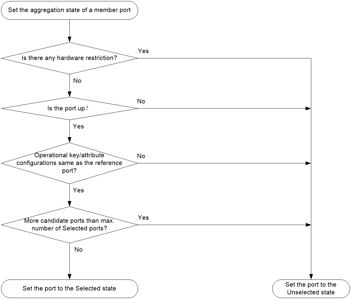
After the limit on Selected ports is reached, the aggregation state of a new member port varies by following conditions:
· The port is placed in Unselected state if the port and the Selected ports have the same port priority. This mechanism prevents traffic interruption on the existing Selected ports. A device reboot can cause the device to recalculate the aggregation states of member ports.
· The port is placed in Selected state when the following conditions are met:
¡ The port and the Selected ports have different port priorities, and the port has a higher port priority than a minimum of one Selected port.
¡ The port has the same attribute configurations as the aggregate interface.
Any operational key or attribute configuration change might affect the aggregation states of link aggregation member ports.
Dynamic link aggregation
Methods to assign interfaces to a dynamic link aggregation group
You can use one of the following methods to assign interfaces to a dynamic link aggregation group:
· Manual assignment—Manually assign interfaces to the dynamic link aggregation group.
· Automatic assignment—Enable automatic assignment on interfaces to have them automatically join a dynamic link aggregation group depending on the peer information in the received LACPDUs.
|
|
NOTE: When you use automatic assignment on one end, you must use manual assignment on the other end. |
LACP
Dynamic aggregation is implemented through IEEE 802.3ad Link Aggregation Control Protocol (LACP).
LACP uses LACPDUs to exchange aggregation information between LACP-enabled devices. Each member port in a dynamic aggregation group can exchange information with its peer. When a member port receives an LACPDU, it compares the received information with information received on the other member ports. In this way, the two systems reach an agreement on which ports are placed in Selected state.
LACP functions
LACP offers basic LACP functions and extended LACP functions, as described in Table 2.
Table 2 Basic and extended LACP functions
|
Category |
Description |
|
Basic LACP functions |
Implemented through the basic LACPDU fields, including the LACP system priority, system MAC address, port priority, port number, and operational key. |
|
Extended LACP functions |
Implemented by extending the LACPDU with new TLV fields. Extended LACP can implement LACP MAD for the IRF feature. The switch series can participate in LACP MAD as either an IRF member device or an intermediate device. For more information about IRF and the LACP MAD mechanism, see Virtual Technologies Configuration Guide. |
LACP operating modes
LACP can operate in active or passive mode.
When LACP is operating in passive mode on a local member port and its peer port, both ports cannot send LACPDUs. When LACP is operating in active mode on either end of a link, both ports can send LACPDUs.
LACP priorities
LACP priorities include LACP system priority and port priority, as described in Table 3. The smaller the priority value, the higher the priority.
|
Type |
Description |
|
System LACP priority |
Used by two peer devices (or systems) to determine which one is superior in link aggregation. In dynamic link aggregation, the system that has higher LACP system priority sets the Selected state of member ports on its side. The system that has lower priority sets the aggregation state of local member ports the same as their respective peer ports. |
|
Port priority |
Determines the likelihood of a member port to be a Selected port on a system. A port with a higher port priority is more likely to become Selected. |
LACP timeout interval
The LACP timeout interval specifies how long a member port waits to receive LACPDUs from the peer port. If a local member port has not received LACPDUs from the peer in 3 seconds after the LACP timeout interval expires, the member port considers the peer as failed.
The LACP timeout interval also determines the LACPDU sending rate of the peer. LACP timeout intervals include the following types:
· Short timeout interval—3 seconds. If you use the short timeout interval, the peer sends one LACPDU per second.
· Long timeout interval—90 seconds. If you use the long timeout interval, the peer sends one LACPDU every 30 seconds.
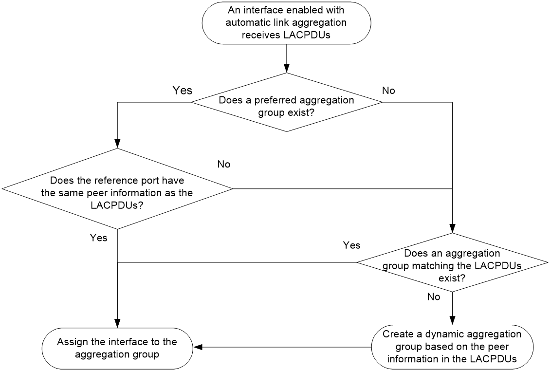
Automatic member interface assignment
As shown in Figure 3, an interface enabled with automatic assignment joins a dynamic aggregation group based on the peer information in the LACPDUs received from the aggregation peer. If none of the existing dynamic aggregation groups is qualified, the device automatically creates a new dynamic aggregation group.
In a dynamic aggregation group that contains both automatically and manually added member ports, the device selects a reference port preferentially from the manually added member ports. The device selects a reference port from automatically added member ports only when manually added member ports are not available.
Figure 3 Automatic member interface assignment process
How dynamic link aggregation works
Choosing a reference port
The system chooses a reference port from the member ports in up state. A Selected port must have the same operational key and attribute configurations as the reference port.
The local system (the actor) and the peer system (the partner) negotiate a reference port by using the following workflow:
1. The two systems determine the system with the smaller system ID.
A system ID contains the LACP system priority and the system MAC address.
a. The two systems compare their LACP priority values.
The lower the LACP priority, the smaller the system ID. If the LACP priority values are the same, the two systems proceed to step b.
b. The two systems compare their MAC addresses.
The lower the MAC address, the smaller the system ID.
2. The system with the smaller system ID chooses the port with the smallest port ID as the reference port.
A port ID contains a port priority and a port number. The lower the port priority, the smaller the port ID.
a. The system chooses the port with the lowest priority value as the reference port.
If the ports have the same priority, the system proceeds to step b.
b. The system compares their port numbers.
The smaller the port number, the smaller the port ID.
The port with the smallest port number and the same attribute configurations as the aggregate interface is chosen as the reference port.
|
|
NOTE: To identify the port numbers of aggregation member ports, execute the display link-aggregation verbose command and examine the Index field in the command output. |
Setting the aggregation state of each member port
After the reference port is chosen, the system with the smaller system ID sets the state of each member port on its side.
Figure 4 Setting the state of a member port in a dynamic aggregation group
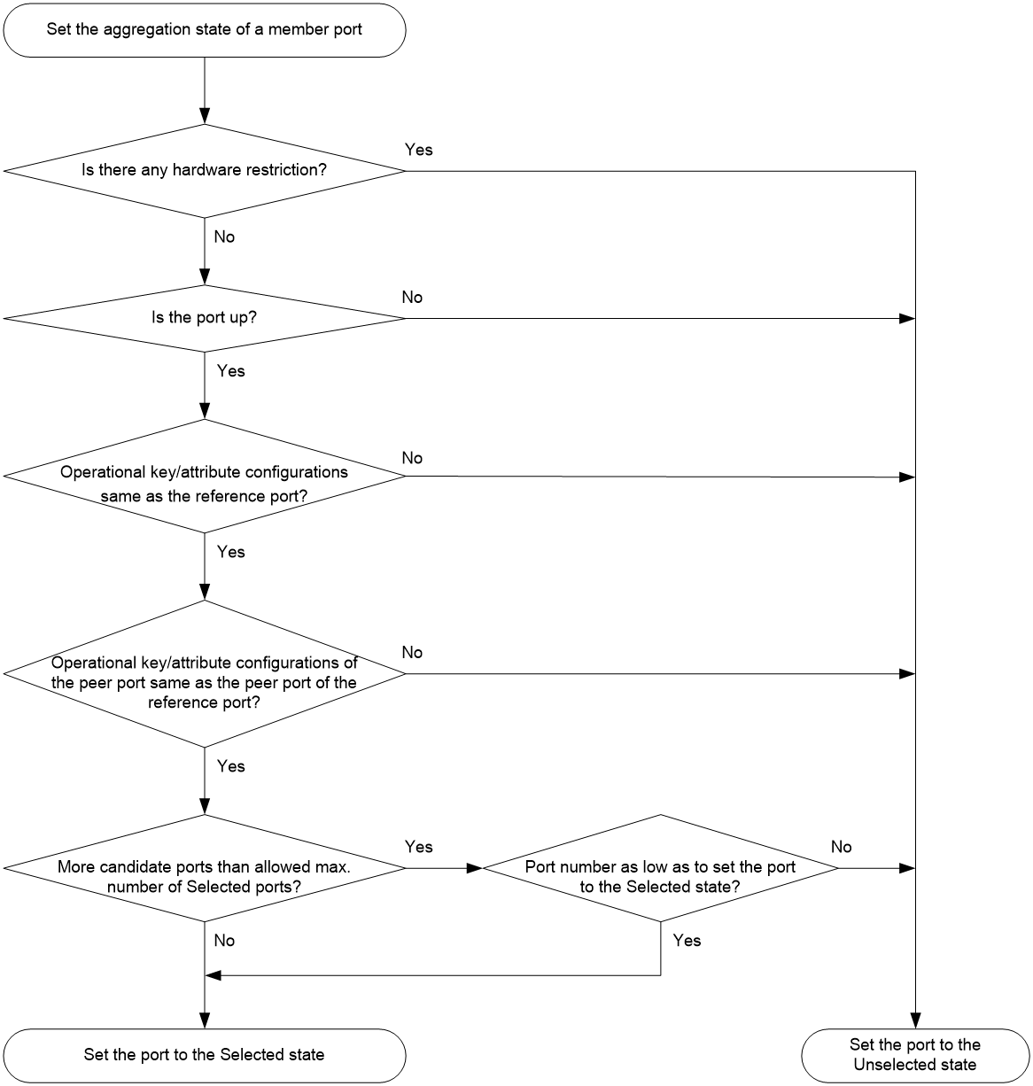
The system with the greater system ID can detect the aggregation state changes on the peer system. The system with the greater system ID sets the aggregation state of local member ports the same as their peer ports.
When you aggregate interfaces in dynamic mode, follow these guidelines:
· A dynamic link aggregation group chooses only full-duplex ports as the Selected ports.
· For stable aggregation and service continuity, do not change the operational key or attribute configurations on any member port.
· After the Selected port limit is reached, a newly joining port becomes a Selected port if it is more eligible than a current Selected port.
Edge aggregate interface
Dynamic link aggregation fails on a server-facing aggregate interface if dynamic link aggregation is configured only on the device. The device forwards traffic by using only one of the physical ports that are connected to the server.
To improve link reliability, configure the aggregate interface as an edge aggregate interface. This feature enables all member ports of the aggregation group to forward traffic. When a member port fails, its traffic is automatically switched to other member ports.
After dynamic link aggregation is configured on the server, the device can receive LACPDUs from the server. Then, link aggregation between the device and the server operates correctly.
An edge aggregate interface takes effect only when it is configured on an aggregate interface corresponding to a dynamic aggregation group.
Load sharing modes for link aggregation groups
In a link aggregation group, traffic can be load shared across the Selected ports based on any of the following modes:
· Per-flow load sharing—Load shares traffic on a per-flow basis. The load sharing mode classifies packets into flows and forwards packets of the same flow on the same link. This mode can be one or any combination of the following traffic classification criteria:
¡ Ingress port.
¡ Source or destination IP address.
¡ Source or destination MAC address.
¡ Source or destination port number.
· Packet type-based load sharing—Load shares traffic automatically based on packet types (Layer 2 protocol, IPv4, or IPv6).
S-MLAG
|
|
IMPORTANT: This feature is supported in R2612 and later. |
Simple multichassis link aggregation (S-MLAG) enhances dynamic link aggregation to establish an aggregation that spans multiple devices to a remote device.
An S-MLAG multichassis aggregation connects one dynamic Layer 2 aggregate interface on each S-MLAG device to the remote device, as shown in Figure 5.
S-MLAG uses an S-MLAG group to manage the aggregate interfaces for each aggregation, and it runs LACP to maintain each aggregation as does dynamic link aggregation. To the remote device, the S-MLAG devices appear as one peer aggregation system.
Figure 5 S-MLAG application scenario
Ethernet link aggregation configuration task list
Configuring an aggregation group
This section explains how to configure an aggregation group.
Configuration restrictions and guidelines for link aggregation configuration
The following information describes restrictions and guidelines that you must follow when you configure link aggregations.
Aggregation member interface restrictions
· You cannot assign an interface to a Layer 2 aggregation group if any features in Table 4 are configured on the interface.
Table 4 Features incompatible with Layer 2 aggregation member interfaces
|
Feature on the interface |
Reference |
|
MAC authentication |
MAC authentication in Security Configuration Guide |
|
Port security |
Port security in Security Configuration Guide |
|
802.1X |
802.1X in Security Configuration Guide |
· Do not assign a reflector port for port mirroring to an aggregation group. For more information about reflector ports, see Network Management and Monitoring Configuration Guide.
· A Layer 2 extended-link aggregation group can contain only extended ports that are on the PEXs in the same PEX group and at the same tier.
Configuration consistency requirements
· You must configure the same aggregation mode at the two ends of an aggregate link.
· For a successful static aggregation, make sure the ports at both ends of each link are in the same aggregation state.
· For a successful dynamic aggregation:
¡ Make sure the peer ports of the ports aggregated at one end are also aggregated. The two ends can automatically negotiate the aggregation state of each member port.
¡ If you use automatic interface assignment on one end, you must use manual assignment on the other end.
· For correct traffic forwarding, make sure the member ports in an aggregation group have the same VLAN mapping configuration.
Layer 3 aggregate subinterface restrictions
If you associate a VPN instance with a Layer 3 aggregate subinterface, you must also perform one or both of the following tasks:
· Associate the VPN instance with the following interfaces:
¡ The Layer 3 Ethernet subinterfaces that have the same subinterface number as the Layer 3 aggregate subinterface.
¡ The VLAN interface that has the same number as the subinterface number of the Layer 3 aggregate subinterface.
· Enable packet statistics for the Layer 3 aggregate subinterface.
For more information about Layer 3 Ethernet subinterfaces, see "Configuring Ethernet interfaces."
For more information about VLAN interfaces, see "Configuring VLANs."
For more information about VPN instance configuration for interfaces, see MPLS L3VPN and MCE configuration in MPLS Configuration Guide.
Miscellaneous
Deleting an aggregate interface also deletes its aggregation group and causes all member ports to leave the aggregation group.
Configuring a Layer 2 aggregation group
Configuring a Layer 2 static aggregation group
|
Step |
Command |
Remarks |
|
1. Enter system view. |
system-view |
N/A |
|
2. Create a Layer 2 aggregate interface and enter Layer 2 aggregate interface view. |
interface bridge-aggregation interface-number [ pex ] |
When you create a Layer 2 aggregate interface, the system automatically creates a Layer 2 static aggregation group numbered the same. To create a Layer 2 extended-link aggregate interface, specify the pex keyword. Do not specify the pex keyword when you create Layer 2 aggregate interface Bridge-Aggregation 1. |
|
3. Exit to system view. |
quit |
N/A |
|
4. Assign an interface to a Layer 2 aggregation group. |
a Enter Layer 2 Ethernet interface view: b Assign the interface to the specified Layer 2 aggregation group: |
Repeat these two substeps to assign more Layer 2 Ethernet interfaces to the aggregation group. To synchronize the attribute configurations from the aggregate interface when the current interface joins the aggregation group, you must specify the force keyword. |
|
5. (Optional.) Set the port priority for the interface. |
link-aggregation port-priority priority |
The default port priority of an interface is 32768. |
Configuring a Layer 2 dynamic aggregation group
|
Step |
Command |
Remarks |
|
1. Enter system view. |
system-view |
N/A |
|
2. Set the LACP system priority. |
lacp system-priority priority |
By default, the LACP system priority is 32768. Changing the LACP system priority might affect the aggregation states of the ports in a dynamic aggregation group. |
|
3. Create a Layer 2 aggregate interface and enter Layer 2 aggregate interface view. |
interface bridge-aggregation interface-number [ pex ] |
When you create a Layer 2 aggregate interface, the system automatically creates a Layer 2 static aggregation group numbered the same. To create a Layer 2 extended-link aggregate interface, specify the pex keyword. Do not specify the pex keyword when you create Layer 2 aggregate interface Bridge-Aggregation 1. |
|
4. Configure the aggregation group to operate in dynamic mode. |
link-aggregation mode dynamic |
By default, an aggregation group operates in static mode. |
|
5. Exit to system view. |
quit |
N/A |
|
6. Assign an interface to a Layer 2 aggregation group or enable automatic assignment on that interface. |
a Enter Layer 2 Ethernet interface view: b Assign the interface to a Layer 2 aggregation group or configure
automatic assignment: |
Repeat these two substeps to assign more Layer 2 Ethernet interfaces to the aggregation group. To synchronize the attribute configurations from the aggregate interface when the current interface joins the aggregation group, you must specify the force keyword. To enable automatic assignment, specify the auto keyword. |
|
7. Set the LACP operating mode for the interface. |
· Set the LACP operating mode to passive: · Set the LACP operating mode to active: |
By default, LACP is operating in active mode. |
|
8. Set the port priority for the interface. |
link-aggregation port-priority priority |
The default setting is 32768. |
|
9. Set the short LACP timeout interval (3 seconds) for the interface. |
lacp period short |
By default, the long LACP timeout interval (90 seconds) is used by the interface. To avoid traffic interruption during an ISSU, do not set the short LACP timeout interval before performing the ISSU. For more information about ISSU, see Fundamentals Configuration Guide. |
Configuring a Layer 3 aggregation group
Configuring a Layer 3 static aggregation group
|
Step |
Command |
Remarks |
|
1. Enter system view. |
system-view |
N/A |
|
2. Create a Layer 3 aggregate interface and enter Layer 3 aggregate interface view. |
interface route-aggregation interface-number |
When you create a Layer 3 aggregate interface, the system automatically creates a Layer 3 static aggregation group numbered the same. |
|
3. Exit to system view. |
quit |
N/A |
|
4. Assign an interface to a Layer 3 aggregation group. |
a Enter Layer 3 Ethernet interface view: b Assign the interface to the specified Layer 3 aggregation group: |
Repeat these two substeps to assign more Layer 3 Ethernet interfaces to the aggregation group. |
|
5. (Optional.) Set the port priority for the interface. |
link-aggregation port-priority priority |
The default port priority of an interface is 32768. |
Configuring a Layer 3 dynamic aggregation group
|
Step |
Command |
Remarks |
|
1. Enter system view. |
system-view |
N/A |
|
2. Set the LACP system priority. |
lacp system-priority priority |
By default, the LACP system priority is 32768. Changing the LACP system priority might affect the aggregation states of the ports in the dynamic aggregation group. |
|
3. Create a Layer 3 aggregate interface and enter Layer 3 aggregate interface view. |
interface route-aggregation interface-number |
When you create a Layer 3 aggregate interface, the system automatically creates a Layer 3 static aggregation group numbered the same. |
|
4. Configure the aggregation group to operate in dynamic mode. |
link-aggregation mode dynamic |
By default, an aggregation group operates in static mode. |
|
5. Exit to system view. |
quit |
N/A |
|
6. Assign an interface to a Layer 3 aggregation group or enable automatic assignment on that interface. |
a Enter Layer 3 Ethernet interface view: b Assign the interface to a Layer 3 aggregation group or configure
automatic assignment: |
Repeat these two substeps to assign more Layer 3 Ethernet interfaces to the aggregation group. To enable automatic assignment, specify the auto keyword. |
|
7. Set the LACP operating mode for the interface. |
· Set the LACP operating mode to passive: · Set the LACP operating mode to active: |
By default, LACP is operating in active mode. |
|
8. Set the port priority for the interface. |
link-aggregation port-priority priority |
The default setting is 32768. |
|
9. Set the short LACP timeout interval (3 seconds) for the interface. |
lacp period short |
By default, the long LACP timeout interval (90 seconds) is used by the interface. To avoid traffic interruption during an ISSU, do not set the short LACP timeout interval before performing the ISSU. For more information about ISSU, see Fundamentals Configuration Guide. |
Configuring an S-channel bundle group
Configuring a static S-channel bundle group
|
Step |
Command |
Remarks |
|
1. Enter system view. |
system-view |
N/A |
|
2. Create an S-channel bundle interface and enter S-channel bundle interface view. |
interface schannel-bundle interface-number |
When you create an S-channel bundle interface, the system automatically creates a static S-channel bundle group numbered the same. |
|
3. Exit to system view. |
quit |
N/A |
|
4. Assign an S-channel interface to an S-channel bundle group. |
a Enter S-channel interface view: b Assign the interface to the specified
S-channel bundle group: |
Repeat these two substeps to assign more S-channel interfaces to the bundle group. To synchronize the attribute configurations from the aggregate interface when the current interface joins the aggregation group, you must specify the force keyword. For more information about EVB, see EVB Configuration Guide. |
|
5. (Optional.) Set the port priority for the interface. |
a link-aggregation port-priority priority |
The default port priority of an interface is 32768. |
Configuring a dynamic S-channel bundle group
|
Step |
Command |
Remarks |
|
1. Enter system view. |
system-view |
N/A |
|
2. Set the LACP system priority. |
lacp system-priority priority |
By default, the LACP system priority is 32768. Changing the LACP system priority might affect the aggregation states of the ports in the dynamic S-channel bundle group. |
|
3. Create an S-channel bundle interface and enter S-channel bundle interface view. |
interface schannel-bundle interface-number |
When you create an S-channel bundle interface, the system automatically creates a static S-channel bundle group numbered the same. |
|
4. Configure the bundle group to operate in dynamic mode. |
link-aggregation mode dynamic |
By default, an S-channel bundle group operates in static mode. |
|
5. Exit to system view. |
quit |
N/A |
|
6. Assign an S-channel interface to an S-channel bundle group. |
a Enter S-channel interface view: b Assign the interface to the specified
S-channel bundle group: |
Repeat these two substeps to assign more S-channel interfaces to the bundle group. To synchronize the attribute configurations from the aggregate interface when the current interface joins the aggregation group, you must specify the force keyword. For more information about EVB, see EVB Configuration Guide. |
|
7. Set the LACP operating mode for the interface. |
· Set the LACP operating mode to passive: · Set the LACP operating mode to active: |
By default, LACP is operating in active mode. |
|
8. Set the port priority for the interface. |
link-aggregation port-priority priority |
The default port priority of an interface is 32768. |
|
9. (Optional.) Set the short LACP timeout interval (3 seconds) for the interface. |
lacp period short |
By default, the long LACP timeout interval (90 seconds) is used by the interface. To avoid traffic interruption during an ISSU, do not set the short LACP timeout interval before performing the ISSU. For more information about ISSU, see Fundamentals Configuration Guide. |
Configuring an aggregate interface
Most configurations that can be made on Layer 2 or Layer 3 Ethernet interfaces can also be made on Layer 2 or Layer 3 aggregate interfaces.
Configuring the description of an aggregate interface
You can configure the description of an aggregate interface for administration purposes, for example, describing the purpose of the interface.
To configure the description of an aggregate interface:
|
Step |
Command |
Remarks |
|
1. Enter system view. |
system-view |
N/A |
|
2. Enter aggregate interface or subinterface view. |
· Enter Layer 2 aggregate interface view: · Enter Layer 3 aggregate interface or
subinterface view: · Enter S-channel bundle interface view: |
N/A |
|
3. Configure the description of the aggregate interface or subinterface. |
description text |
By default, the description of an interface is interface-name Interface. |
Changing the MAC address of a Layer 3 aggregate interface or subinterface
By default, all Layer 3 aggregate interfaces and subinterfaces on a device use the same MAC address. The default MAC address of Layer 3 aggregate interfaces and subinterfaces varies by device.
Do not use this command on a border gateway of a VXLAN or EVPN network.
The bridge MAC address of the device and its subsequent higher 169 consecutive MAC addresses are reserved. To avoid forwarding failure, do not assign a reserved MAC address to an aggregate interface or subinterface.
To avoid forwarding failure after an IRF master/subordinate switchover, do not assign the IRF bridge MAC address to an aggregate interface or subinterface. For more information about the IRF bridge MAC address, see Virtual Technologies Configuration Guide.
To change the MAC address of an aggregate interface:
|
Step |
Command |
Remarks |
|
1. Enter system view. |
system-view |
N/A |
|
2. Enter Layer 3 aggregate interface or subinterface view. |
interface route-aggregation { interface-number | interface-number.subnumber } |
N/A |
|
3. Change the MAC address of the aggregate interface. |
mac-address mac-address |
By default, all Layer 3 aggregate interfaces and subinterfaces on the device use the same default MAC address. You can use the display interface command to view the MAC address of a Layer 3 aggregate interface or subinterface. |
Specifying ignored VLANs for a Layer 2 aggregate interface
This feature takes effect only when the link type of a Layer 2 aggregate interface is hybrid or trunk.
To become Selected, the member ports by default must have the same VLAN permit state and tagging mode as the Layer 2 aggregate interface.
This feature enables the system to ignore the permit state and tagging mode of an ignored VLAN when choosing Selected ports.
To specify ignored VLANs for a Layer 2 aggregate interface:
|
Step |
Command |
Remarks |
|
1. Enter system view. |
system-view |
N/A |
|
2. Enter Layer 2 aggregate interface view. |
interface bridge-aggregation interface-number |
N/A |
|
3. Specify ignored VLANs. |
link-aggregation ignore vlan vlan-id-list |
By default, a Layer 2 aggregate interface does not ignore any VLANs. |
Ignoring port speed in setting the aggregation states of member ports
This feature allows ports at a different speed than the reference port to become Selected by ignoring the port speed during operational key calculation.
You must configure the same port speed ignoring setting at the two ends of a static configuration to ensure that the peer ports are placed in the same aggregation state. This requirement does not apply to a dynamic aggregation, on which the two ends negotiate the aggregation state of the peer ports automatically.
To configure an aggregation group to ignore port speed in setting the aggregation states of member ports:
|
Step |
Command |
Remarks |
|
1. Enter system view. |
system-view |
N/A |
|
2. Enter aggregate interface view. |
· Enter Layer 2 aggregate interface view: · Enter Layer 3 aggregate interface view: |
N/A |
|
3. Configure the aggregation group to ignore port speed in setting the aggregation states of member ports. |
link-aggregation ignore speed |
By default, an aggregation group does not ignore port speed in setting the aggregation states of member ports. |
Setting the MTU for a Layer 3 aggregate interface
The MTU of an interface affects IP packets fragmentation and reassembly on the interface.
To set the MTU for a Layer 3 aggregate interface:
|
Step |
Command |
Remarks |
|
1. Enter system view. |
system-view |
N/A |
|
2. Enter Layer 3 aggregate interface or subinterface view. |
interface route-aggregation { interface-number | interface-number.subnumber } |
N/A |
|
3. Set the MTU for the Layer 3 aggregate interface or subinterface. |
mtu size |
The default setting is 1500 bytes. |
Setting the minimum and maximum numbers of Selected ports for an aggregation group
About the minimum and maximum numbers of Selected ports for an aggregation group
The bandwidth of an aggregate link increases as the number of Selected member ports increases. To avoid congestion, you can set the minimum number of Selected ports required for bringing up an aggregate interface.
This minimum threshold setting affects the aggregation states of aggregation member ports and the state of the aggregate interface.
· When the number of member ports eligible to be Selected ports is smaller than the minimum threshold, the following events occur:
¡ The eligible member ports are placed in Unselected state.
¡ The link layer state of the aggregate interface becomes down.
· When the number of member ports eligible to be Selected ports reaches or exceeds the minimum threshold, the following events occur:
¡ The eligible member ports are placed in Selected state.
¡ The link layer state of the aggregate interface becomes up.
The maximum number of Selected ports allowed in an aggregation group is limited by either manual configuration or hardware limitation, whichever value is smaller.
You can implement backup between two ports by performing the following tasks:
· Assigning two ports to an aggregation group.
· Setting the maximum number of Selected ports to 1 for the aggregation group.
Then, only one Selected port is allowed in the aggregation group, and the Unselected port acts as a backup port.
Configuration restrictions and guidelines
The minimum and maximum numbers of Selected ports must be the same for the local and peer aggregation groups.
Configuration procedure
To set the minimum and maximum numbers of Selected ports for an aggregation group:
|
Step |
Command |
Remarks |
|
1. Enter system view. |
system-view |
N/A |
|
2. Enter aggregate interface view. |
· Enter Layer 2 aggregate interface view: · Enter Layer 3 aggregate interface view: · Enter S-channel bundle interface view: |
N/A |
|
3. Set the minimum number of Selected ports for the aggregation group. |
link-aggregation selected-port minimum min-number |
By default, the minimum number of Selected ports is not specified for an aggregation group. |
|
4. Set the maximum number of Selected ports for the aggregation group. |
link-aggregation selected-port maximum max-number |
By default, the maximum number of Selected ports for an aggregation group is 32. |
Setting the expected bandwidth for an aggregate interface
|
Step |
Command |
Remarks |
|
1. Enter system view. |
system-view |
N/A |
|
2. Enter aggregate interface view. |
· Enter Layer 2 aggregate interface view: · Enter Layer 3 aggregate interface or subinterface
view: · Enter S-channel bundle interface view: |
N/A |
|
3. Set the expected bandwidth for the interface. |
bandwidth bandwidth-value |
By default, the expected bandwidth (in kbps) is the interface baud rate divided by 1000. |
Configuring an edge aggregate interface
When you configure an edge aggregate interface, follow these restrictions and guidelines:
· This configuration takes effect only on the aggregate interface corresponding to a dynamic aggregation group.
· Configure only aggregate interfaces connected to endpoints such as servers as edge aggregate interfaces. Do not connect edge aggregate interfaces to network devices.
· Link-aggregation traffic redirection does not operate correctly on an edge aggregate interface. For more information about link-aggregation traffic redirection, see "Enabling link-aggregation traffic redirection."
To configure an edge aggregate interface:
|
Step |
Command |
Remarks |
|
1. Enter system view. |
system-view |
N/A |
|
2. Enter aggregate interface view. |
· Enter Layer 2 aggregate interface view: · Enter Layer 3 aggregate interface view: · Enter S-channel bundle interface view: |
N/A |
|
3. Configure the aggregate interface as an edge aggregate interface. |
lacp edge-port |
By default, an aggregate interface does not operate as an edge aggregate interface. |
Enabling BFD for an aggregation group
About BFD for Ethernet link aggregation
You can use BFD to monitor member link status in an aggregation group. After you enable BFD on an aggregate interface, each Selected port in the aggregation group establishes a BFD session with its peer port. BFD operates differently depending on the aggregation mode.
· BFD on a static aggregation—When BFD detects a link failure, BFD notifies the Ethernet link aggregation module that the peer port is unreachable. The local port is then placed in Unselected state. However, the BFD session between the local and peer ports remains, and the local port keeps sending BFD packets. When BFD on the local port receives packets from the peer port upon link recovery, BFD notifies the Ethernet link aggregation module that the peer port is reachable. Then, the local port is placed in Selected state again. This mechanism ensures that the local and peer ports of a static aggregate link have the same aggregation state.
· BFD on a dynamic aggregation—When BFD detects a link failure, BFD notifies the Ethernet link aggregation module that the peer port is unreachable. At the same time, BFD clears the session and stops sending BFD packets. When the local port is placed in Selected state again upon link recovery, the local port establishes a new session with the peer port and BFD notifies the Ethernet link aggregation module that the peer port is reachable. Because BFD provides fast failure detection, the local and peer systems of a dynamic aggregate link can negotiate the aggregation state of their member ports faster.
For more information about BFD, see High Availability Configuration Guide.
Configuration restrictions and guidelines
When you enable BFD for an aggregation group, follow these restrictions and guidelines:
· Make sure the source and destination IP addresses are consistent at the two ends of an aggregate link. For example, if you execute link-aggregation bfd ipv4 source 1.1.1.1 destination 2.2.2.2 on the local end, execute link-aggregation bfd ipv4 source 2.2.2.2 destination 1.1.1.1 on the peer end. The source and destination IP addresses cannot be the same.
· The BFD parameters configured on an aggregate interface take effect on all BFD sessions established by the member ports in its aggregation group. BFD on a link aggregation supports only control packet mode for session establishment and maintenance. The two ends of an established BFD session can only operate in Asynchronous mode.
· As a best practice, do not configure BFD for any protocols on a BFD-enabled aggregate interface.
· Make sure the number of member ports in a BFD-enabled aggregation group is less than or identical to the number of BFD sessions supported by the device. If the aggregation group contains more member ports than the supported sessions, some Selected ports might change to the Unselected state.
· If the number of BFD sessions differs between the two ends of an aggregate link, check their settings for inconsistency in the maximum number of Selected ports. You must make sure the two ends have the same setting for the maximum number of Selected ports.
Configuration procedure
To enable BFD for an aggregation group:
|
Step |
Command |
Remarks |
|
1. Enter system view. |
system-view |
N/A |
|
2. Enter aggregate interface view. |
· Enter Layer 2 aggregate interface view: · Enter Layer 3 aggregate interface view: |
N/A |
|
3. Enable BFD for the aggregation group. |
link-aggregation bfd ipv4 source ip-address destination ip-address |
By default, BFD is disabled for an aggregation group. The source and destination IP addresses of BFD sessions must be unicast addresses excluding 0.0.0.0. |
Configuring a dynamic aggregation group to use port speed as the prioritized criterion for reference port selection
|
|
CAUTION: · Changing reference port selection criteria might cause transient traffic interruption. Make sure you understand the impact of this task on your network. · You must perform this task at both ends of the aggregate link so the peer aggregation systems use the same criteria for reference port selection. |
Perform this task to ensure that a dynamic aggregation group selects a high-speed member port as the reference port.
To configure a dynamic aggregation group to use port speed as the prioritized criterion for reference port selection:
|
Step |
Command |
Remarks |
|
1. Enter system view. |
system-view |
N/A |
|
2. Enter aggregate interface view. |
· Enter Layer 2 aggregate interface view: · Enter Layer 3 aggregate interface view: · Enter S-channel bundle interface view: |
N/A |
|
3. Shut down the interface. |
shutdown |
Changing reference port selection criteria might causes transient traffic interruption. As a best practice, shut down the aggregate interface before you make a change. |
|
4. Specify port speed as the prioritized criterion for reference port selection. |
lacp select speed |
By default, port ID is the prioritized criterion for reference port selection of a dynamic aggregation group. |
|
5. Bring up the interface. |
undo shutdown |
N/A |
Shutting down an aggregate interface
Shutting down or bringing up an aggregate interface affects the aggregation states and link states of member ports in the corresponding aggregation group as follows:
· When an aggregate interface is shut down, all Selected ports in the corresponding aggregation group become Unselected ports and all member ports go down.
· When an aggregate interface is brought up, the aggregation states of member ports in the corresponding aggregation group are recalculated.
To shut down an aggregate interface:
|
Step |
Command |
|
1. Enter system view. |
system-view |
|
2. Enter aggregate interface view. |
· Enter Layer 2 aggregate interface view: · Enter Layer 3 aggregate interface or
subinterface view: · Enter S-channel bundle interface view: |
|
3. Shut down the aggregate interface or subinterface. |
shutdown |
Enabling packet statistics for a Layer 3 aggregate subinterface
|
|
IMPORTANT: This feature is supported only in R2612 and later. |
The packet statistics feature is CPU intensive. When you use this command for Layer 3 aggregate subinterfaces, make sure you fully understand its impact on system performance.
This feature collects only incoming packet statistics on Layer 3 aggregate subinterfaces.
To enable packet statistics for a Layer 3 aggregate subinterface:
|
Step |
Command |
Remarks |
|
1. Enter system view. |
system-view |
N/A |
|
2. Enter Layer 3 aggregate subinterface view. |
interface route-aggregation interface-number.subnumber |
N/A |
|
3. Enable packet statistics for the Layer 3 aggregate subinterface. |
traffic-statistic enable |
By default, the packet statistics feature is disabled for a Layer 3 aggregate subinterface. |
|
4. (Optional.) Display the packet statistics for the Layer 3 aggregate subinterface. |
display interface route-aggregation interface-number.subnumber |
In the command output, the Input field displays packet statistics. |
Restoring the default settings for an aggregate interface
You can restore all configurations on an aggregate interface to the default settings.
To restore the default settings for an aggregate interface:
|
Step |
Command |
|
1. Enter system view. |
system-view |
|
2. Enter aggregate interface view. |
· Enter Layer 2 aggregate interface view: · Enter Layer 3 aggregate interface or
subinterface view: · Enter S-channel bundle interface view: |
|
3. Restore the default settings for the aggregate interface. |
default |
Configuring load sharing for link aggregation groups
This section explains how to configure the load sharing modes for link aggregation groups and how to enable local-first load sharing for link aggregation.
Setting load sharing modes for link aggregation groups
You can set the global or group-specific load sharing mode. A link aggregation group preferentially uses the group-specific load sharing mode. If the group-specific load sharing mode is not available, the group uses the global load sharing mode.
The destination port and source port criteria of the global load sharing mode also take effect on aggregation groups that have group-specific load sharing settings. If the global load sharing mode contains one or both of these criteria, these aggregation groups use both the port load sharing settings and group-specific load sharing settings.
The following are global load sharing modes supported on the device:
· Load sharing mode automatically determined based on the packet type.
· Source IP.
· Destination IP.
· Source MAC.
|
NOTE: Packets will not be load shared based on their source MAC addresses if their destination IP addresses match multiport ARP entries. For more information about multiport ARP entries, see Layer 3—IP Services Configuration Guide. |
· Destination MAC.
· Layer 1 MPLS label.
· Layer 2 MPLS label.
· Source IP and destination IP.
· Source IP and source port.
· Destination IP and destination port.
· Layer 1 MPLS label and Layer 2 MPLS label.
· Source IP, source port, destination IP, and destination port.
· Any combination of ingress port, source MAC, and destination MAC.
The following are the link sharing modes supported in aggregate interface view:
· Load sharing mode automatically determined based on the packet type.
· Source IP.
· Destination IP.
· Source MAC.
|
NOTE: Packets will not be load shared based on their source MAC addresses if their destination IP addresses match multiport ARP entries. For more information about multiport ARP entries, see Layer 3—IP Services Configuration Guide. |
· Destination MAC.
· Destination IP and source IP.
· Destination MAC and source MAC.
Setting the global link-aggregation load sharing mode
|
Step |
Command |
Remarks |
|
1. Enter system view. |
system-view |
N/A |
|
2. Set the global link-aggregation load sharing mode. |
link-aggregation global load-sharing mode { destination-ip | destination-mac | destination-port | ingress-port | mpls-label1 | mpls-label2 | source-ip | source-mac | source-port } * |
By default, the device selects a load sharing mode for packets depending on their packet type, as follows: · Layer 3 (or IP) packets (frames with a value of 0x0800 or 0x86DD in the EtherType field) are load shared based on the following information: ¡ Source and destination IP addresses. ¡ Source and destination TCP/UDP port numbers. ¡ IP protocol number. · Layer 2 packets (frames with a value that is not either 0x0800 or 0x86DD in the EtherType field) are load shared based on the following information: ¡ Source and destination MAC addresses. ¡ EtherType value. ¡ VLAN tag. ¡ Mod ID. ¡ Incoming and outgoing port numbers. |
Setting the group-specific load sharing mode
|
Step |
Command |
Remarks |
|
1. Enter system view. |
system-view |
N/A |
|
2. Enter aggregate interface view. |
· Enter Layer 2 aggregate interface view: · Enter Layer 3 aggregate interface view: |
N/A |
|
3. Set the load sharing mode for the aggregation group. |
link-aggregation load-sharing mode { { destination-ip | destination-mac | source-ip | source-mac } * | flexible } |
By default, the group-specific load sharing mode is the same as the global load sharing mode. |
Specifying ignored packet fields for default link-aggregation load sharing
In default load sharing mode, an aggregation group might fail to load share traffic in a balanced manner. To resolve the problem, you can configure the device to ignore specific packet fields for link-aggregation load sharing. The specified packet field values are ignored during the load sharing calculation.
To specify ignored packet fields for default link-aggregation load sharing:
|
Step |
Command |
Remarks |
|
1. Enter system view. |
system-view |
N/A |
|
2. Specify ignored packet fields for default link-aggregation load sharing. |
link-aggregation load-sharing ignore { destination-ip | destination-mac | destination-port | ethernet-type | ingress-port | ip-protocol | mpls-label1 | mpls-label2 | mpls-label3 | source-ip | source-mac | source-port | vlan-id } * |
By default, no ignored packet fields are specified for default link-aggregation load sharing. |
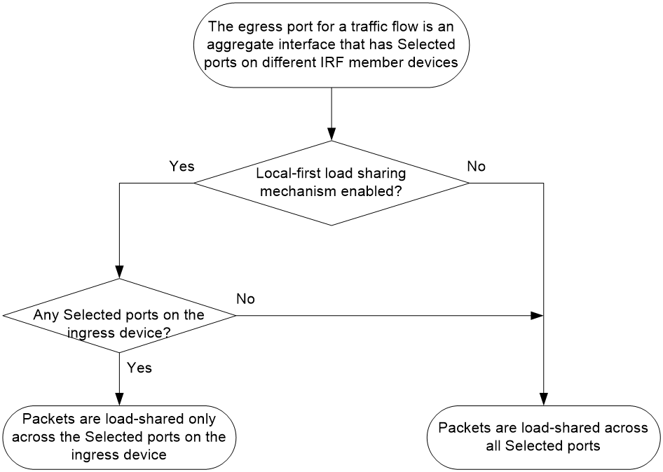
Enabling local-first load sharing for link aggregation
About local-first load sharing
Use local-first load sharing in a multidevice link aggregation scenario to distribute traffic preferentially across member ports on the ingress device.
When you aggregate ports on different member devices in an IRF fabric, you can use local-first load sharing to reduce traffic on IRF links, as shown in Figure 6. For more information about IRF, see Virtual Technologies Configuration Guide.
Figure 6 Load sharing for multidevice link aggregation in an IRF fabric
Configuration restrictions and guidelines
On a VXLAN network, you must enable local-first load sharing on the transport-facing interface for a VXLAN tunnel if that interface is one of the following types:
· Layer 3 aggregate interface.
· VLAN interface for a VLAN that contains Layer 2 aggregate interfaces.
For more information about VXLAN, see VXLAN Configuration Guide.
Configuration procedure
To enable local-first load sharing for link aggregation:
|
Step |
Command |
Remarks |
|
1. Enter system view. |
system-view |
N/A |
|
2. Enable local-first load sharing for link aggregation. |
link-aggregation load-sharing mode local-first |
By default, local-first load sharing for link aggregation is enabled. |
Configuring link aggregation load sharing algorithm settings
To optimize traffic distribution on aggregate links, you can configure the link aggregation load sharing algorithm and the hash seed. The algorithm determines the CRC calculation method. The hash seed is a parameter used in hashing.
In default load sharing mode, if the device fails to load share traffic flows across all Selected ports, repeat the following procedure until the problem is resolved:
1. Configure the load sharing algorithm or hash seed. You can specify algorithm 1 to 8 in sequence.
2. Use the display counters command to view traffic statistics on Selected ports.
You can use a load sharing algorithm and a hash seed individually or in combination to obtain the optimal load sharing performance.
This feature does not take effect on per-flow load sharing.
To configure a link aggregation load sharing algorithm:
|
Step |
Command |
Remarks |
|
1. Enter system view. |
system-view |
N/A |
|
2. Configure a link aggregation load sharing algorithm. |
link-aggregation global load-sharing algorithm algorithm-number |
By default, algorithm 5 is used. |
|
3. Configure a link aggregation load sharing hash seed. |
link-aggregation global load-sharing seed seed-number |
By default, hash seed 0 is used. |
Setting the global load sharing mode for MAC-in-MAC traffic
Perform this task to set the global load sharing mode for MAC-in-MAC traffic on the aggregate links of a backbone core bridge. For more information about backbone core bridges, see "Configuring PBB."
MAC-in-MAC traffic can be load shared based on any of the following items:
· The outer frame header, and source and destination ports.
· The inner frame header, and source and destination ports.
To set the global load sharing mode for MAC-in-MAC traffic:
|
Step |
Command |
Remarks |
|
1. Enter system view. |
system-view |
N/A |
|
2. Set the global load sharing mode for MAC-in-MAC traffic. |
link-aggregation global load-sharing minm { inner | outer } |
By default, MAC-in-MAC traffic is load shared based on the inner frame header, and source and destination ports. |
Enabling link-aggregation traffic redirection
About link-aggregation traffic redirection
This feature redirects traffic on a Selected port to the remaining available Selected ports of an aggregation group if one of the following events occurs:
· The port is shut down by using the shutdown command.
· The slot that hosts the port reboots, and the aggregation group spans multiple slots.
This feature ensures zero packet loss for known unicast traffic, but does not protect unknown unicast traffic.
You can enable link-aggregation traffic redirection globally or for an aggregation group. Global link-aggregation traffic redirection settings take effect on all aggregation groups. A link aggregation group preferentially uses the group-specific link-aggregation traffic redirection settings. If group-specific link-aggregation traffic redirection is not configured, the group uses the global link-aggregation traffic redirection settings.
Configuration restrictions and guidelines
When you enable link-aggregation traffic redirection, follow these restrictions and guidelines:
· Link-aggregation traffic redirection applies only to dynamic link aggregation groups.
· To prevent traffic interruption, enable link-aggregation traffic redirection on devices at both ends of the aggregate link.
· To prevent packet loss that might occur when a slot reboots, do not enable spanning tree together with link-aggregation traffic redirection.
· Link-aggregation traffic redirection does not operate correctly on an edge aggregate interface.
· As a best practice, enable link-aggregation traffic redirection on aggregate interfaces. If you enable this feature globally, communication with a third-party peer device might be affected if the peer is not compatible with this feature.
Enabling link-aggregation traffic globally
|
Step |
Command |
Remarks |
|
1. Enter system view. |
system-view |
N/A |
|
2. Enable link-aggregation traffic redirection globally. |
link-aggregation lacp traffic-redirect-notification enable |
By default, link-aggregation traffic redirection is disabled globally. |
Enabling link-aggregation traffic redirection for an aggregation group
|
Step |
Command |
Remarks |
|
1. Enter system view. |
system-view |
N/A |
|
2. Enter aggregate interface view. |
· Enter Layer 2 aggregate interface view: · Enter Layer 3 aggregate interface view: |
N/A |
|
3. Enable link-aggregation traffic redirection for the aggregation group. |
link-aggregation lacp traffic-redirect-notification enable |
By default, link-aggregation traffic redirection is disabled for an aggregation group. |
Specifying link aggregation management VLANs and management port
For an aggregation group to forward Layer 3 data traffic of some VLANs through a specific port, specify the VLANs as management VLANs and the port as a management port.
To specify link aggregation management VLANs and management port for an aggregation group:
|
Step |
Command |
Remarks |
|
1. Enter system view. |
system-view |
N/A |
|
2. Specify link aggregation management VLANs. |
link-aggregation management-vlan vlan-id-list |
By default, no link aggregation management VLANs are specified. |
|
3. Enter Layer 2 Ethernet interface view. |
interface interface-type interface-number |
N/A |
|
4. Configure the port as a management port for its aggregation group. |
link-aggregation management-port |
By default, a port does not act as a management port in its aggregation group. |
Excluding a subnet from load sharing on aggregate links
About excluding subnets from load sharing on aggregate links
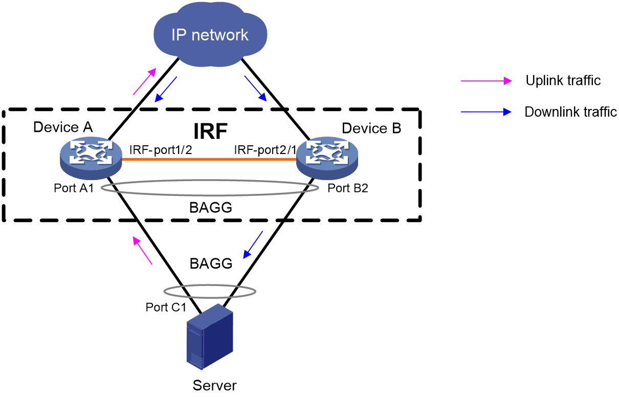
Typically, an aggregate interface distributes traffic across its Selected member ports. The uplink and downlink traffic of a host might be distributed to different member ports, as shown in Figure 7. To make sure the bidirectional traffic of a subnet traverses the same member port, you can exclude that subnet from load sharing by specifying it as a link aggregation management subnet.
When an aggregate interface receives an ARP packet from the management subnet, the device looks up the sender IP address in the ARP table for a matching entry.
· If no matching entry exists, the device creates an ARP entry on the aggregation member port from which the packet came in. This mechanism ensures that the returned downlink traffic will be forwarded out of the member port that received the uplink traffic.
· If an ARP entry already exists on a different port than the aggregate interface or its member ports, the device does not update that ARP entry. Instead, the device broadcasts an ARP request out of all ports to relearn the ARP entry.
When an aggregate interface sends an ARP packet to the management subnet, the device sends the packet out of all Selected member ports of the aggregate interface.
As shown in Figure 7, an aggregate link is established between the server and the IRF fabric. The server sends all uplink traffic of a subnet through Port C1 to Port A1 on the IRF fabric. If that subnet is not specified as a management subnet, the IRF fabric distributes its downlink traffic across Port A1 and Port B2. To send the downlink traffic of that subnet to the server only through Port A1, you can specify the subnet as a link aggregation management subnet.
Figure 7 Link aggregation scenario before management subnets are used
Configuration restrictions and guidelines
You can configure a maximum of 20 management subnets.
To ensure correct packet forwarding, delete all ARP entries of a subnet before you specify it as a management subnet or after you remove it from the management subnet list.
If you are using link aggregation management subnets, do not use the following features:
· DRNI. For more information, see Layer 2—LAN Switching Configuration Guide.
· ARP snooping. For more information, see Layer 3—IP Services Configuration Guide.
· MPLS L2VPN. For more information, see MPLS Configuration Guide.
Configuration procedure
To exclude a subnet from load sharing on aggregate links:
|
Step |
Command |
Remarks |
|
1. Enter system view. |
system-view |
N/A |
|
2. Specify a link aggregation management subnet. |
link-aggregation management-subnet ip-address { mask | mask-length } |
By default, no link aggregation management subnets are specified. |
Enabling a Layer 2 aggregate interface to reflect incoming packets back
By default, the device drops a packet if its outgoing interface is the incoming interface where the packet arrived. To have a Layer 2 aggregate interface reflect a packet back when it is both the incoming and outgoing interfaces of that packet, perform this task.
To enable a Layer 2 aggregate interface to reflect incoming packets back:
|
Step |
Command |
Remarks |
|
1. Enter system view. |
system-view |
N/A |
|
2. Enter Layer 2 aggregate interface view. |
interface bridge-aggregation interface-number |
N/A |
|
3. Enable port bridging. |
port bridge enable |
By default, port bridging is disabled. A Layer 2 aggregate interface cannot reflect incoming packets back. |
Enabling transparent LACPDU transmission
About transparent LACPDU transmission
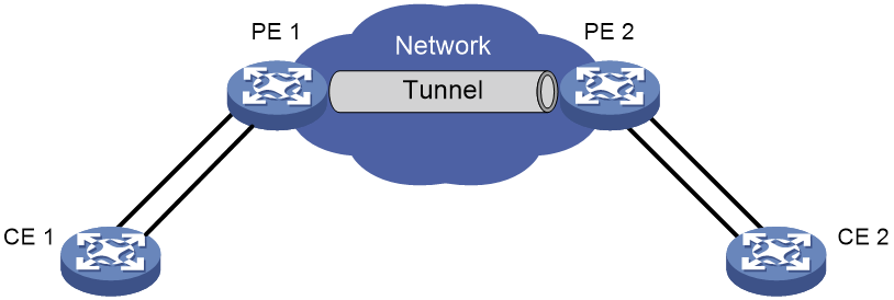
To establish a dynamic aggregation between two remote CEs in an L2VPN network, use transparent LACPDU transmission on the PEs to which the CEs attached, as shown in Figure 8.
This feature enables the PEs to forward LACPDUs for the CEs to establish a dynamic aggregation.
If this feature is disabled, the PEs terminate the LACPDUs. The remote CEs cannot establish dynamic aggregations.
Figure 8 Application scenario of transparent LACPDU transmission
Configuration prerequisites
Perform the following tasks on PEs:
1. Configure the untagged or default frame match criterion for the Ethernet service instances on the interfaces connected to CEs.
2. Map the Ethernet service instances to different VSIs and set the access mode to Ethernet for the VSIs.
For more information about Ethernet service instances, see VPLS and MPLS L2VPN configuration in MPLS Configuration Guide.
Configuration restrictions and guidelines
When you use this feature on the PEs, follow these guidelines:
· Enable transparent LACPDU transmission on the interfaces that transmit traffic between CEs and PEs and between PEs.
· Do not use an interface for link aggregation if you enable transparent LACPDU transmission on that interface. With transparent LACPDU transmission enabled, an interface cannot be selected for aggregation.
Configuration procedure
To enable transparent LACPDU transmission on an interface:
|
Step |
Command |
Remarks |
|
1. Enter system view. |
system-view |
N/A |
|
2. Enter interface view. |
interface interface-type interface-number |
N/A |
|
3. Enable transparent LACPDU transmission. |
lacp transparent enable |
By default, transparent LACPDU transmission is disabled. |
Configuring S-MLAG
Configuration restrictions and guidelines
This feature is supported only in R2612 and later.
S-MLAG is intended for a non-IRF environment. Do not configure it on an IRF fabric. For more information about IRF, see Virtual Technologies Configuration Guide.
An S-MLAG group can contain only one aggregate interface on each device.
The aggregate interfaces in an S-MLAG group cannot be used as DR interfaces or IPPs in DRNI. For more information about DR interfaces and IPPs, see "Configuring DRNI."
Do not configure the following settings on S-MLAG devices:
· LACP MAD.
· Link-aggregation traffic redirection.
· Maximum or minimum number of Selected ports.
· Automatic member port assignment.
· Ignoring port speed in setting the aggregation states of member ports.
As a best practice, maintain consistency across S-MLAG devices in service feature configuration.
Configuration prerequisites
Configure the link aggregation settings other than S-MLAG settings on each S-MLAG device. Make sure the settings are consistent across the S-MLAG devices.
Configuration procedure
|
Step |
Command |
Remarks |
|
1. Enter system view. |
system-view |
N/A |
|
2. Set the LACP system MAC address. |
lacp system-mac mac-address |
By default, the LACP system MAC address is the bridge MAC address of the device. All S-MLAG devices must use the same LACP system MAC address. |
|
3. Set the LACP system priority. |
lacp system-priority priority |
By default, the LACP system priority is 32768. All S-MLAG devices must use the same LACP system priority. |
|
4. Set the LACP system number. |
lacp system-number number |
By default, the LACP system number is not set. You must assign a unique LACP system number to each S-MLAG device. |
|
5. Enter Layer 2 aggregate interface view. |
interface bridge-aggregation interface-number |
N/A |
|
6. Set the link aggregation mode to dynamic. |
link-aggregation mode dynamic |
By default, an aggregation group operates in static mode. |
|
7. Assign the aggregate interface to an S-MLAG group. |
port s-mlag group group-id |
By default, an aggregate interface is not assigned to any S-MLAG group. |
Displaying and maintaining Ethernet link aggregation
Execute display commands in any view and reset commands in user view.
|
Task |
Command |
|
Display information for an aggregate interface or multiple aggregate interfaces. |
display interface [ { bridge-aggregation | route-aggregation | schannel-bundle } [ interface-number ] ] [ brief [ description | down ] ] |
|
Display the local system ID. |
display lacp system-id |
|
Display the global or group-specific link-aggregation load sharing modes. |
display link-aggregation load-sharing mode [ interface [ { bridge-aggregation | route-aggregation | schannel-bundle } interface-number ] ] |
|
Display forwarding information for the specified traffic flow. |
display link-aggregation load-sharing path interface { bridge-aggregation | route-aggregation } interface-number ingress-port interface-type interface-number [ route ] { { destination-ip ip-address | destination-ipv6 ipv6-address } | { source-ip ip-address | source-ipv6 ipv6-address } | destination-mac mac-address | destination-port port-id | ethernet-type type-number | ip-protocol protocol-id | source-mac mac-address | source-port port-id | vlan vlan-id } * |
|
Display detailed link aggregation information for link aggregation member ports. |
display link-aggregation member-port [ interface-list | auto ] |
|
Display summary information about all aggregation groups. |
display link-aggregation summary |
|
Display detailed information about the specified aggregation groups. |
display link-aggregation verbose [ { bridge-aggregation | route-aggregation | schannel-bundle } [ interface-number ] ] |
|
Clear LACP statistics for the specified link aggregation member ports. |
reset lacp statistics [ interface interface-list ] |
|
Clear statistics for the specified aggregate interfaces. |
reset counters interface [ { bridge-aggregation | route-aggregation | schannel-bundle } [ interface-number ] ] |
Ethernet link aggregation configuration examples
Layer 2 static aggregation configuration example
Network requirements
On the network shown in Figure 9, perform the following tasks:
· Configure a Layer 2 static aggregation group on both Device A and Device B.
· Enable VLAN 10 at one end of the aggregate link to communicate with VLAN 10 at the other end.
· Enable VLAN 20 at one end of the aggregate link to communicate with VLAN 20 at the other end.

Configuration procedure
1. Configure Device A:
# Create VLAN 10, and assign port Ten-GigabitEthernet 1/0/4 to VLAN 10.
<DeviceA> system-view
[DeviceA] vlan 10
[DeviceA-vlan10] port ten-gigabitethernet 1/0/4
[DeviceA-vlan10] quit
# Create VLAN 20, and assign port Ten-GigabitEthernet 1/0/5 to VLAN 20.
[DeviceA] vlan 20
[DeviceA-vlan20] port ten-gigabitethernet 1/0/5
[DeviceA-vlan20] quit
# Create Layer 2 aggregate interface Bridge-Aggregation 1.
[DeviceA] interface bridge-aggregation 1
[DeviceA-Bridge-Aggregation1] quit
# Assign ports Ten-GigabitEthernet 1/0/1 through Ten-GigabitEthernet 1/0/3 to link aggregation group 1.
[DeviceA] interface ten-gigabitethernet 1/0/1
[DeviceA-Ten-GigabitEthernet1/0/1] port link-aggregation group 1
[DeviceA-Ten-GigabitEthernet1/0/1] quit
[DeviceA] interface ten-gigabitethernet 1/0/2
[DeviceA-Ten-GigabitEthernet1/0/2] port link-aggregation group 1
[DeviceA-Ten-GigabitEthernet1/0/2] quit
[DeviceA] interface ten-gigabitethernet 1/0/3
[DeviceA-Ten-GigabitEthernet1/0/3] port link-aggregation group 1
[DeviceA-Ten-GigabitEthernet1/0/3] quit
# Configure Layer 2 aggregate interface Bridge-Aggregation 1 as a trunk port and assign it to VLANs 10 and 20.
[DeviceA] interface bridge-aggregation 1
[DeviceA-Bridge-Aggregation1] port link-type trunk
[DeviceA-Bridge-Aggregation1] port trunk permit vlan 10 20
[DeviceA-Bridge-Aggregation1] quit
2. Configure Device B in the same way Device A is configured. (Details not shown.)
Verifying the configuration
# Display detailed information about all aggregation groups on Device A.
[DeviceA] display link-aggregation verbose
Loadsharing Type: Shar -- Loadsharing, NonS -- Non-Loadsharing
Port Status: S -- Selected, U -- Unselected, I -- Individual
Port: A -- Auto port, M -- Management port, R -- Reference port
Flags: A -- LACP_Activity, B -- LACP_Timeout, C -- Aggregation,
D -- Synchronization, E -- Collecting, F -- Distributing,
G -- Defaulted, H -- Expired
Aggregate Interface: Bridge-Aggregation1
Aggregation Mode: Static
Loadsharing Type: NonS
Management VLANs: None
Port Status Priority Oper-Key
XGE1/0/1 S 32768 1
XGE1/0/2 S 32768 1
XGE1/0/3 S 32768 1
The output shows that link aggregation group 1 is a Layer 2 static aggregation group that contains three Selected ports.
Layer 2 dynamic aggregation configuration example
Network requirements
On the network shown in Figure 10, perform the following tasks:
· Configure a Layer 2 dynamic aggregation group on both Device A and Device B.
· Enable VLAN 10 at one end of the aggregate link to communicate with VLAN 10 at the other end.
· Enable VLAN 20 at one end of the aggregate link to communicate with VLAN 20 at the other end.
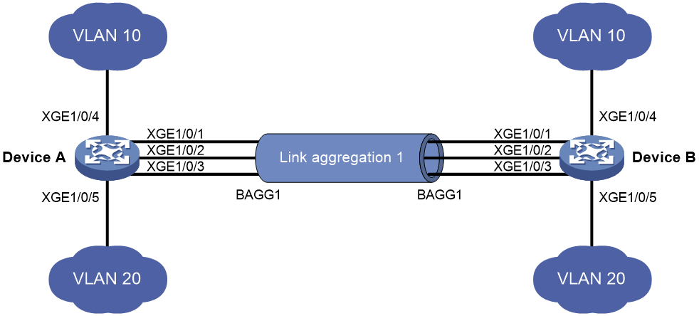
Configuration procedure
1. Configure Device A:
# Create VLAN 10, and assign the port Ten-GigabitEthernet 1/0/4 to VLAN 10.
<DeviceA> system-view
[DeviceA] vlan 10
[DeviceA-vlan10] port ten-gigabitethernet 1/0/4
[DeviceA-vlan10] quit
# Create VLAN 20, and assign the port Ten-GigabitEthernet 1/0/5 to VLAN 20.
[DeviceA] vlan 20
[DeviceA-vlan20] port ten-gigabitethernet 1/0/5
[DeviceA-vlan20] quit
# Create Layer 2 aggregate interface Bridge-Aggregation 1, and set the link aggregation mode to dynamic.
[DeviceA] interface bridge-aggregation 1
[DeviceA-Bridge-Aggregation1] link-aggregation mode dynamic
[DeviceA-Bridge-Aggregation1] quit
# Assign ports Ten-GigabitEthernet 1/0/1 through Ten-GigabitEthernet 1/0/3 to link aggregation group 1.
[DeviceA] interface ten-gigabitethernet 1/0/1
[DeviceA-Ten-GigabitEthernet1/0/1] port link-aggregation group 1
[DeviceA-Ten-GigabitEthernet1/0/1] quit
[DeviceA] interface ten-gigabitethernet 1/0/2
[DeviceA-Ten-GigabitEthernet1/0/2] port link-aggregation group 1
[DeviceA-Ten-GigabitEthernet1/0/2] quit
[DeviceA] interface ten-gigabitethernet 1/0/3
[DeviceA-Ten-GigabitEthernet1/0/3] port link-aggregation group 1
[DeviceA-Ten-GigabitEthernet1/0/3] quit
# Configure Layer 2 aggregate interface Bridge-Aggregation 1 as a trunk port and assign it to VLANs 10 and 20.
[DeviceA] interface bridge-aggregation 1
[DeviceA-Bridge-Aggregation1] port link-type trunk
[DeviceA-Bridge-Aggregation1] port trunk permit vlan 10 20
[DeviceA-Bridge-Aggregation1] quit
2. Configure Device B in the same way Device A is configured. (Details not shown.)
Verifying the configuration
# Display detailed information about all aggregation groups on Device A.
[DeviceA] display link-aggregation verbose
Loadsharing Type: Shar -- Loadsharing, NonS -- Non-Loadsharing
Port Status: S -- Selected, U -- Unselected, I -- Individual
Port: A -- Auto port, M -- Management port, R -- Reference port
Flags: A -- LACP_Activity, B -- LACP_Timeout, C -- Aggregation,
D -- Synchronization, E -- Collecting, F -- Distributing,
G -- Defaulted, H -- Expired
Aggregate Interface: Bridge-Aggregation1
Aggregation Mode: Dynamic
Loadsharing Type: NonS
Management VLANs: None
System ID: 0x8000, 000f-e267-6c6a
Local:
Port Status Priority Index Oper-Key Flag
XGE1/0/1(R) S 32768 11 1 {ACDEF}
XGE1/0/2 S 32768 12 1 {ACDEF}
XGE1/0/3 S 32768 13 1 {ACDEF}
Remote:
Actor Priority Index Oper-Key SystemID Flag
XGE1/0/1 32768 81 1 0x8000, 000f-e267-57ad {ACDEF}
XGE1/0/2 32768 82 1 0x8000, 000f-e267-57ad {ACDEF}
XGE1/0/3 32768 83 1 0x8000, 000f-e267-57ad {ACDEF}
The output shows that link aggregation group 1 is a Layer 2 dynamic aggregation group that contains three Selected ports.
Layer 2 aggregation load sharing configuration example
Network requirements
On the network shown in Figure 11, perform the following tasks:
· Configure Layer 2 static aggregation groups 1 and 2 on Device A and Device B, respectively.
· Enable VLAN 10 at one end of the aggregate link to communicate with VLAN 10 at the other end.
· Enable VLAN 20 at one end of the aggregate link to communicate with VLAN 20 at the other end.
· Configure link aggregation groups 1 and 2 to load share traffic across aggregation group member ports.
¡ Configure link aggregation group 1 to load share packets based on source MAC addresses.
¡ Configure link aggregation group 2 to load share packets based on destination MAC addresses.
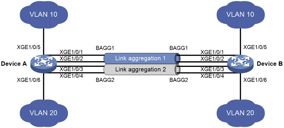
Configuration procedure
1. Configure Device A:
# Create VLAN 10, and assign the port Ten-GigabitEthernet 1/0/5 to VLAN 10.
<DeviceA> system-view
[DeviceA] vlan 10
[DeviceA-vlan10] port ten-gigabitethernet 1/0/5
[DeviceA-vlan10] quit
# Create VLAN 20, and assign the port Ten-GigabitEthernet 1/0/6 to VLAN 20.
[DeviceA] vlan 20
[DeviceA-vlan20] port ten-gigabitethernet 1/0/6
[DeviceA-vlan20] quit
# Create Layer 2 aggregate interface Bridge-Aggregation 1.
[DeviceA] interface bridge-aggregation 1
# Configure Layer 2 aggregation group 1 to load share packets based on source MAC addresses.
[DeviceA-Bridge-Aggregation1] link-aggregation load-sharing mode source-mac
[DeviceA-Bridge-Aggregation1] quit
# Assign ports Ten-GigabitEthernet 1/0/1 and Ten-GigabitEthernet 1/0/2 to link aggregation group 1.
[DeviceA] interface ten-gigabitethernet 1/0/1
[DeviceA-Ten-GigabitEthernet1/0/1] port link-aggregation group 1
[DeviceA-Ten-GigabitEthernet1/0/1] quit
[DeviceA] interface ten-gigabitethernet 1/0/2
[DeviceA-Ten-GigabitEthernet1/0/2] port link-aggregation group 1
[DeviceA-Ten-GigabitEthernet1/0/2] quit
# Configure Layer 2 aggregate interface Bridge-Aggregation 1 as a trunk port and assign it to VLAN 10.
[DeviceA] interface bridge-aggregation 1
[DeviceA-Bridge-Aggregation1] port link-type trunk
[DeviceA-Bridge-Aggregation1] port trunk permit vlan 10
[DeviceA-Bridge-Aggregation1] quit
# Create Layer 2 aggregate interface Bridge-Aggregation 2.
[DeviceA] interface bridge-aggregation 2
# Configure Layer 2 aggregation group 2 to load share packets based on destination MAC addresses.
[DeviceA-Bridge-Aggregation2] link-aggregation load-sharing mode destination-mac
[DeviceA-Bridge-Aggregation2] quit
# Assign ports Ten-GigabitEthernet 1/0/3 and Ten-GigabitEthernet 1/0/4 to link aggregation group 2.
[DeviceA] interface ten-gigabitethernet 1/0/3
[DeviceA-Ten-GigabitEthernet1/0/3] port link-aggregation group 2
[DeviceA-Ten-GigabitEthernet1/0/3] quit
[DeviceA] interface ten-gigabitethernet 1/0/4
[DeviceA-Ten-GigabitEthernet1/0/4] port link-aggregation group 2
[DeviceA-Ten-GigabitEthernet1/0/4] quit
# Configure Layer 2 aggregate interface Bridge-Aggregation 2 as a trunk port and assign it to VLAN 20.
[DeviceA] interface bridge-aggregation 2
[DeviceA-Bridge-Aggregation2] port link-type trunk
[DeviceA-Bridge-Aggregation2] port trunk permit vlan 20
[DeviceA-Bridge-Aggregation2] quit
2. Configure Device B in the same way Device A is configured. (Details not shown.)
Verifying the configuration
# Display detailed information about all aggregation groups on Device A.
[DeviceA] display link-aggregation verbose
Loadsharing Type: Shar -- Loadsharing, NonS -- Non-Loadsharing
Port Status: S -- Selected, U -- Unselected, I -- Individual
Port: A -- Auto port, M -- Management port, R -- Reference port
Flags: A -- LACP_Activity, B -- LACP_Timeout, C -- Aggregation,
D -- Synchronization, E -- Collecting, F -- Distributing,
G -- Defaulted, H -- Expired
Aggregate Interface: Bridge-Aggregation1
Aggregation Mode: Static
Loadsharing Type: Shar
Management VLANs: None
Port Status Priority Oper-Key
XGE1/0/1 S 32768 1
XGE1/0/2 S 32768 1
Aggregate Interface: Bridge-Aggregation2
Aggregation Mode: Static
Loadsharing Type: Shar
Management VLANs: None
Port Status Priority Oper-Key
XGE1/0/3 S 32768 2
XGE1/0/4 S 32768 2
The output shows that:
· Link aggregation groups 1 and 2 are both load-shared Layer 2 static aggregation groups.
· Each aggregation group contains two Selected ports.
# Display all the group-specific load sharing modes on Device A.
[DeviceA] display link-aggregation load-sharing mode interface
Bridge-Aggregation1 Load-Sharing Mode:
source-mac address
Bridge-Aggregation2 Load-Sharing Mode:
destination-mac address
The output shows that:
· Link aggregation group 1 load shares packets based on source MAC addresses.
· Link aggregation group 2 load shares packets based on destination MAC addresses.
Layer 2 edge aggregate interface configuration example
Network requirements
As shown in Figure 12, a Layer 2 dynamic aggregation group is configured on the device. The server is not configured with dynamic link aggregation.
Configure an edge aggregate interface so that both Ten-GigabitEthernet 1/0/1 and Ten-GigabitEthernet 1/0/2 can forward traffic to improve link reliability.

Configuration procedure
# Create Layer 2 aggregate interface Bridge-Aggregation 1, and set the link aggregation mode to dynamic.
<Device> system-view
[Device] interface bridge-aggregation 1
[Device-Bridge-Aggregation1] link-aggregation mode dynamic
# Configure Layer 2 aggregate interface Bridge-Aggregation 1 as an edge aggregate interface.
[Device-Bridge-Aggregation1] lacp edge-port
[Device-Bridge-Aggregation1] quit
# Assign ports Ten-GigabitEthernet 1/0/1 and Ten-GigabitEthernet 1/0/2 to link aggregation group 1.
[Device] interface ten-gigabitethernet 1/0/1
[Device-Ten-GigabitEthernet1/0/1] port link-aggregation group 1
[Device-Ten-GigabitEthernet1/0/1] quit
[Device] interface ten-gigabitethernet 1/0/2
[Device-Ten-GigabitEthernet1/0/2] port link-aggregation group 1
[Device-Ten-GigabitEthernet1/0/2] quit
Verifying the configuration
# Display detailed information about all aggregation groups on the device when the server is not configured with dynamic link aggregation.
[Device] display link-aggregation verbose
Loadsharing Type: Shar -- Loadsharing, NonS -- Non-Loadsharing
Port Status: S -- Selected, U -- Unselected, I -- Individual
Port: A -- Auto port, M -- Management port, R -- Reference port
Flags: A -- LACP_Activity, B -- LACP_Timeout, C -- Aggregation,
D -- Synchronization, E -- Collecting, F -- Distributing,
G -- Defaulted, H -- Expired
Aggregate Interface: Bridge-Aggregation1
Aggregation Mode: Dynamic
Loadsharing Type: NonS
Management VLANs: None
System ID: 0x8000, 000f-e267-6c6a
Local:
Port Status Priority Index Oper-Key Flag
XGE1/0/1 I 32768 11 1 {AG}
XGE1/0/2 I 32768 12 1 {AG}
Remote:
Actor Priority Index Oper-Key SystemID Flag
XGE1/0/1 32768 81 0 0x8000, 0000-0000-0000 {DEF}
XGE1/0/2 32768 82 0 0x8000, 0000-0000-0000 {DEF}
The output shows that Ten-GigabitEthernet 1/0/1 and Ten-GigabitEthernet 1/0/2 are in Individual state when they do not receive LACPDUs from the server. Both Ten-GigabitEthernet 1/0/1 and Ten-GigabitEthernet 1/0/2 can forward traffic. When one port fails, its traffic is automatically switched to the other port.
Layer 3 static aggregation configuration example
Network requirements
On the network shown in Figure 13, perform the following tasks:
· Configure a Layer 3 static aggregation group on both Device A and Device B.
· Configure IP addresses and subnet masks for the corresponding Layer 3 aggregate interfaces.

Configuration procedure
1. Configure Device A:
# Create Layer 3 aggregate interface Route-Aggregation 1, and configure an IP address and subnet mask for the aggregate interface.
<DeviceA> system-view
[DeviceA] interface route-aggregation 1
[DeviceA-Route-Aggregation1] ip address 192.168.1.1 24
[DeviceA-Route-Aggregation1] quit
# Assign Layer 3 Ethernet interfaces Ten-GigabitEthernet 1/0/1 through Ten-GigabitEthernet 1/0/3 to aggregation group 1.
[DeviceA] interface ten-gigabitethernet 1/0/1
[DeviceA-Ten-GigabitEthernet1/0/1] port link-aggregation group 1
[DeviceA-Ten-GigabitEthernet1/0/1] quit
[DeviceA] interface ten-gigabitethernet 1/0/2
[DeviceA-Ten-GigabitEthernet1/0/2] port link-aggregation group 1
[DeviceA-Ten-GigabitEthernet1/0/2] quit
[DeviceA] interface ten-gigabitethernet 1/0/3
[DeviceA-Ten-GigabitEthernet1/0/3] port link-aggregation group 1
[DeviceA-Ten-GigabitEthernet1/0/3] quit
2. Configure Device B in the same way Device A is configured. (Details not shown.)
Verifying the configuration
# Display detailed information about all aggregation groups on Device A.
[DeviceA] display link-aggregation verbose
Loadsharing Type: Shar -- Loadsharing, NonS -- Non-Loadsharing
Port Status: S -- Selected, U -- Unselected, I -- Individual
Port: A -- Auto port, M -- Management port, R -- Reference port
Flags: A -- LACP_Activity, B -- LACP_Timeout, C -- Aggregation,
D -- Synchronization, E -- Collecting, F -- Distributing,
G -- Defaulted, H -- Expired
Aggregate Interface: Route-Aggregation1
Aggregation Mode: Static
Loadsharing Type: NonS
Management VLANs: None
Port Status Priority Oper-Key
XGE1/0/1 S 32768 1
XGE1/0/2 S 32768 1
XGE1/0/3 S 32768 1
The output shows that link aggregation group 1 is a Layer 3 static aggregation group that contains three Selected ports.
Layer 3 dynamic aggregation configuration example
Network requirements
On the network shown in Figure 14, perform the following tasks:
· Configure a Layer 3 dynamic aggregation group on both Device A and Device B.
· Configure IP addresses and subnet masks for the corresponding Layer 3 aggregate interfaces.

Configuration procedure
1. Configure Device A:
# Create Layer 3 aggregate interface Route-Aggregation 1.
<DeviceA> system-view
[DeviceA] interface route-aggregation 1
# Set the link aggregation mode to dynamic.
[DeviceA-Route-Aggregation1] link-aggregation mode dynamic
# Configure an IP address and subnet mask for Route-Aggregation 1.
[DeviceA-Route-Aggregation1] ip address 192.168.1.1 24
[DeviceA-Route-Aggregation1] quit
# Assign Layer 3 Ethernet interfaces Ten-GigabitEthernet 1/0/1 through Ten-GigabitEthernet 1/0/3 to aggregation group 1.
[DeviceA] interface ten-gigabitethernet 1/0/1
[DeviceA-Ten-GigabitEthernet1/0/1] port link-aggregation group 1
[DeviceA-Ten-GigabitEthernet1/0/1] quit
[DeviceA] interface ten-gigabitethernet 1/0/2
[DeviceA-Ten-GigabitEthernet1/0/2] port link-aggregation group 1
[DeviceA-Ten-GigabitEthernet1/0/2] quit
[DeviceA] interface ten-gigabitethernet 1/0/3
[DeviceA-Ten-GigabitEthernet1/0/3] port link-aggregation group 1
[DeviceA-Ten-GigabitEthernet1/0/3] quit
2. Configure Device B in the same way Device A is configured. (Details not shown.)
Verifying the configuration
# Display detailed information about all aggregation groups on Device A.
[DeviceA] display link-aggregation verbose
Loadsharing Type: Shar -- Loadsharing, NonS -- Non-Loadsharing
Port Status: S -- Selected, U -- Unselected, I -- Individual
Port: A -- Auto port, M -- Management port, R -- Reference port
Flags: A -- LACP_Activity, B -- LACP_Timeout, C -- Aggregation,
D -- Synchronization, E -- Collecting, F -- Distributing,
G -- Defaulted, H -- Expired
Aggregate Interface: Route-Aggregation1
Aggregation Mode: Dynamic
Loadsharing Type: NonS
Management VLANs: None
System ID: 0x8000, 000f-e267-6c6a
Local:
Port Status Priority Index Oper-Key Flag
XGE1/0/1(R) S 32768 11 1 {ACDEF}
XGE1/0/2 S 32768 12 1 {ACDEF}
XGE1/0/3 S 32768 13 1 {ACDEF}
Remote:
Actor Priority Index Oper-Key SystemID Flag
XGE1/0/1 32768 81 1 0x8000, 000f-e267-57ad {ACDEF}
XGE1/0/2 32768 81 1 0x8000, 000f-e267-57ad {ACDEF}
XGE1/0/3 32768 81 1 0x8000, 000f-e267-57ad {ACDEF}
The output shows that link aggregation group 1 is a Layer 3 dynamic aggregation group that contains three Selected ports.
Layer 3 aggregation load sharing configuration example
Network requirements
On the network shown in Figure 15, perform the following tasks:
· Configure Layer 3 static aggregation groups 1 and 2 on Device A and Device B, respectively.
· Configure IP addresses and subnet masks for the corresponding Layer 3 aggregate interfaces.
· Configure link aggregation group 1 to load share packets based on source IP addresses.
· Configure link aggregation group 2 to load share packets based on destination IP addresses.

Configuration procedure
1. Configure Device A:
# Create Layer 3 aggregate interface Route-Aggregation 1.
<DeviceA> system-view
[DeviceA] interface route-aggregation 1
# Configure Layer 3 aggregation group 1 to load share packets based on source IP addresses.
[DeviceA-Route-Aggregation1] link-aggregation load-sharing mode source-ip
# Configure an IP address and subnet mask for Layer 3 aggregate interface Route-Aggregation 1.
[DeviceA-Route-Aggregation1] ip address 192.168.1.1 24
[DeviceA-Route-Aggregation1] quit
# Assign Layer 3 Ethernet interfaces Ten-GigabitEthernet 1/0/1 and Ten-GigabitEthernet 1/0/2 to aggregation group 1.
[DeviceA] interface ten-gigabitethernet 1/0/1
[DeviceA-Ten-GigabitEthernet1/0/1] port link-aggregation group 1
[DeviceA-Ten-GigabitEthernet1/0/1] quit
[DeviceA] interface ten-gigabitethernet 1/0/2
[DeviceA-Ten-GigabitEthernet1/0/2] port link-aggregation group 1
[DeviceA-Ten-GigabitEthernet1/0/2] quit
# Create Layer 3 aggregate interface Route-Aggregation 2.
[DeviceA] interface route-aggregation 2
# Configure Layer 3 aggregation group 2 to load share packets based on destination IP addresses.
[DeviceA-Route-Aggregation2] link-aggregation load-sharing mode destination-ip
# Configure an IP address and subnet mask for Layer 3 aggregate interface Route-Aggregation 2.
[DeviceA-Route-Aggregation2] ip address 192.168.2.1 24
[DeviceA-Route-Aggregation2] quit
# Assign Layer 3 Ethernet interfaces Ten-GigabitEthernet 1/0/3 and Ten-GigabitEthernet 1/0/4 to aggregation group 2.
[DeviceA] interface ten-gigabitethernet 1/0/3
[DeviceA-Ten-GigabitEthernet1/0/3] port link-aggregation group 2
[DeviceA-Ten-GigabitEthernet1/0/3] quit
[DeviceA] interface ten-gigabitethernet 1/0/4
[DeviceA-Ten-GigabitEthernet1/0/4] port link-aggregation group 2
[DeviceA-Ten-GigabitEthernet1/0/4] quit
2. Configure Device B in the same way Device A is configured. (Details not shown.)
Verifying the configuration
# Display detailed information about all aggregation groups on Device A.
[DeviceA] display link-aggregation verbose
Loadsharing Type: Shar -- Loadsharing, NonS -- Non-Loadsharing
Port Status: S -- Selected, U -- Unselected, I -- Individual
Port: A -- Auto port, M -- Management port, R -- Reference port
Flags: A -- LACP_Activity, B -- LACP_Timeout, C -- Aggregation,
D -- Synchronization, E -- Collecting, F -- Distributing,
G -- Defaulted, H -- Expired
Aggregate Interface: Route-Aggregation1
Aggregation Mode: Static
Loadsharing Type: Shar
Management VLANs: None
Port Status Priority Oper-Key
XGE1/0/1 S 32768 1
XGE1/0/2 S 32768 1
Aggregate Interface: Route-Aggregation2
Aggregation Mode: Static
Loadsharing Type: Shar
Management VLANs: None
Port Status Priority Oper-Key
XGE1/0/3 S 32768 2
XGE1/0/4 S 32768 2
The output shows that:
· Link aggregation groups 1 and 2 are both load-shared Layer 3 static aggregation groups.
· Each aggregation group contains two Selected ports.
# Display all the group-specific load sharing modes on Device A.
[DeviceA] display link-aggregation load-sharing mode interface
Route-Aggregation1 Load-Sharing Mode:
source-ip address
Route-Aggregation2 Load-Sharing Mode:
destination-ip address
The output shows that:
· Link aggregation group 1 load shares packets based on source IP addresses.
· Link aggregation group 2 load shares packets based on destination IP addresses.
S-MLAG configuration example
Network requirements
As shown in Figure 16, configure Device B, Device C, and Device D as S-MLAG devices to establish a multichassis aggregate link with Device A.
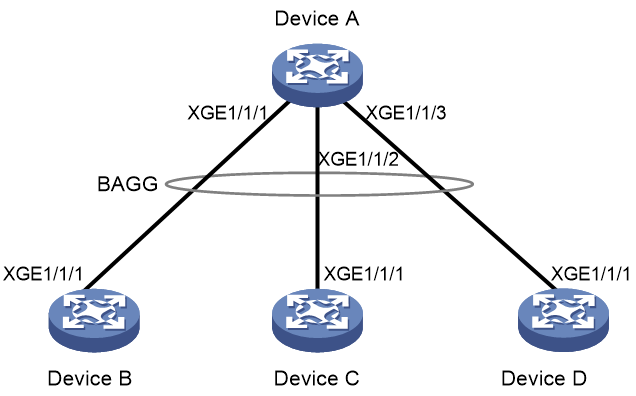
Configuration procedure
1. Configure Device A:
# Create Layer 2 aggregate interface Bridge-Aggregation 10, and set the link aggregation mode to dynamic.
<DeviceA> system-view
[DeviceA] interface bridge-aggregation 10
[DeviceA-Bridge-Aggregation10] link-aggregation mode dynamic
[DeviceA-Bridge-Aggregation10] quit
# Assign Ten-GigabitEthernet 1/0/1 through Ten-GigabitEthernet 1/0/3 to aggregation group 10.
[DeviceA] interface ten-gigabitethernet 1/0/1
[DeviceA-Ten-GigabitEthernet1/0/1] port link-aggregation group 10
[DeviceA-Ten-GigabitEthernet1/0/1] quit
[DeviceA] interface ten-gigabitethernet 1/0/2
[DeviceA-Ten-GigabitEthernet1/0/2] port link-aggregation group 10
[DeviceA-Ten-GigabitEthernet1/0/2] quit
[DeviceA] interface ten-gigabitethernet 1/0/3
[DeviceA-Ten-GigabitEthernet1/0/3] port link-aggregation group 10
[DeviceA-Ten-GigabitEthernet1/0/3] quit
2. Configure Device B:
# Set the LACP system MAC address to 0001-0001-0001.
<DeviceB> system-view
[DeviceB] lacp system-mac 1-1-1
# Set the LACP system priority to 123.
[DeviceB] lacp system-priority 123
# Set the LACP system number to 1.
[DeviceB] lacp system-number 1
# Create Layer 2 aggregate interface Bridge-Aggregation 2, and set the link aggregation mode to dynamic.
[DeviceB] interface bridge-aggregation 2
[DeviceB-Bridge-Aggregation2] link-aggregation mode dynamic
# Assign Bridge-Aggregation 2 to S-MLAG group 100.
[DeviceB-Bridge-Aggregation2] port s-mlag group 100
# Assign Ten-GigabitEthernet 1/0/1 to aggregation group 2.
[DeviceB] interface ten-gigabitethernet 1/0/1
[DeviceB-Ten-GigabitEthernet1/0/1] port link-aggregation group 2
[DeviceB-Ten-GigabitEthernet1/0/1] quit
3. Configure Device C:
# Set the LACP system MAC address to 0001-0001-0001.
<DeviceC> system-view
[DeviceC] lacp system-mac 1-1-1
# Set the LACP system priority to 123.
[DeviceC] lacp system-priority 123
# Set the LACP system number to 2.
[DeviceC] lacp system-number 2
# Create Layer 2 aggregate interface Bridge-Aggregation 3, and set the link aggregation mode to dynamic.
[DeviceC] interface bridge-aggregation 3
[DeviceC-Bridge-Aggregation3] link-aggregation mode dynamic
# Assign Bridge-Aggregation 3 to S-MLAG group 100.
[DeviceC-Bridge-Aggregation3] port s-mlag group 100
# Assign Ten-GigabitEthernet 1/0/1 to aggregation group 3.
[DeviceC] interface ten-gigabitethernet 1/0/1
[DeviceC-Ten-GigabitEthernet1/0/1] port link-aggregation group 3
[DeviceC-Ten-GigabitEthernet1/0/1] quit
4. Configure Device D:
# Set the LACP system MAC address to 0001-0001-0001.
<DeviceD> system-view
[DeviceD] lacp system-mac 1-1-1
# Set the LACP system priority to 123.
[DeviceD] lacp system-priority 123
# Set the LACP system number to 3.
[DeviceD] lacp system-number 3
# Create Layer 2 aggregate interface Bridge-Aggregation 4, and set the link aggregation mode to dynamic.
[DeviceD] interface bridge-aggregation 4
[DeviceD-Bridge-Aggregation4] link-aggregation mode dynamic
# Assign Bridge-Aggregation 4 to S-MLAG group 100.
[DeviceD-Bridge-Aggregation4] port s-mlag group 100
# Assign Ten-GigabitEthernet 1/0/1 to aggregation group 4.
[DeviceD] interface ten-gigabitethernet 1/0/1
[DeviceD-Ten-GigabitEthernet1/0/1] port link-aggregation group 4
[DeviceD-Ten-GigabitEthernet1/0/1] quit
Verifying the configuration
# Verify that Ten-GigabitEthernet 1/0/1 through Ten-GigabitEthernet 1/0/3 on Device A are Selected ports.
[DeviceA] display link-aggregation verbose
Loadsharing Type: Shar -- Loadsharing, NonS -- Non-Loadsharing
Port Status: S -- Selected, U -- Unselected, I -- Individual
Port: A -- Auto port, M -- Management port, R -- Reference port
Flags: A -- LACP_Activity, B -- LACP_Timeout, C -- Aggregation,
D -- Synchronization, E -- Collecting, F -- Distributing,
G -- Defaulted, H -- Expired
Aggregate Interface: Bridge-Aggregation10
Aggregation Mode: Dynamic
Loadsharing Type: Shar
Management VLANs: None
System ID: 0x8000, 40fa-264f-0100
Local:
Port Status Priority Index Oper-Key Flag
XGE1/0/1(R) S 32768 1 1 {ACDEF}
XGE1/0/2 S 32768 2 1 {ACDEF}
XGE1/0/3 S 32768 3 1 {ACDEF}
Remote:
Actor Priority Index Oper-Key SystemID Flag
XGE1/0/1 32768 16385 50100 0x7b , 0001-0001-0001 {ACDEF}
XGE1/0/2 32768 32769 50100 0x7b , 0001-0001-0001 {ACDEF}
XGE1/0/3 32768 49153 50100 0x7b , 0001-0001-0001 {ACDEF}