- Table of Contents
- Related Documents
-
| Title | Size | Download |
|---|---|---|
| 01-Text | 3.23 MB |
Content
Overview
The information in this document might differ from your product if it contains custom configuration options or features.
The figures in this document are for illustration only.
Processor kit
The processor kit for an H3C UniServer R4900 G5 server includes the following components:
· Processor
· Retaining bracket
· Heatsink
T15 and T30 Torx screwdrivers are required for processor installation. A T15 Torx screwdriver is provided with the server. You need to prepare a T30 Torx screwdriver yourself.
Preparing for installation
|
|
WARNING! To reduce the risk of personal injury from hot surfaces, allow the server and the internal system components to cool before touching them. |
|
|
CAUTION: · To avoid processor and system board damage, only H3C-authorized personnel and professional server engineers can install a processor. · When installing or removing the processors, wear a reliably-grounded ESD wrist strap and a pair of ESD gloves to prevent ESD damage to the processors. When installing or removing other components except for the processors, wear a reliably-grounded ESD wrist strap to prevent ESD damage. |
To prepare the server for processor installation:
1. Back up all server data.
2. Power off the server.
3. Disconnect the power cords.
4. Remove the server from the rack.
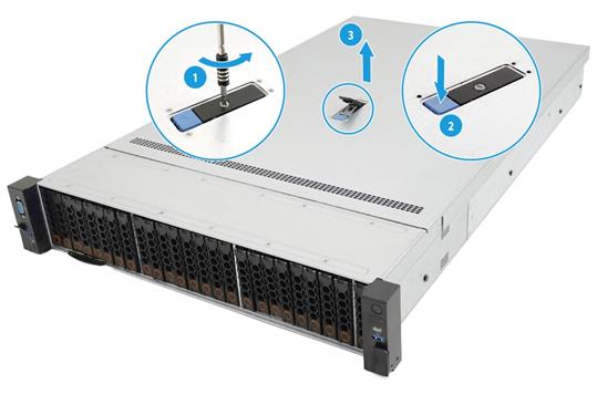
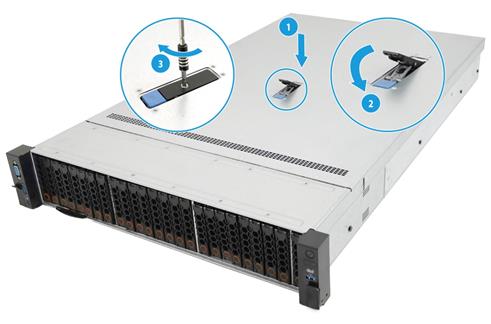
5. Remove the access panel, as shown in Figure1-1.
a. (Optional.) If the access panel is locked, use a Phillips screwdriver to loosen the screw on the locking lever, as shown by callout 1.
b. Press the release button to release the locking lever, and then lift up the locking lever as shown by callout 2. The access panel slides towards the rear of the server automatically.
c. Lift the access panel away from the server, as shown by callout 3.
Figure1-1 Removing the access panel
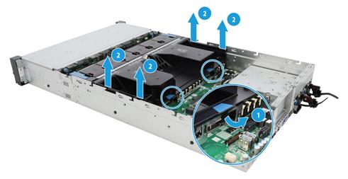
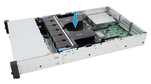
6. Remove the chassis air baffle. As shown in Figure1-2, open the hooks marked by blue trapezoids on the chassis air baffle, and then lift the air baffle up to remove it from the chassis.
Figure1-2 Removing the chassis air baffle
Installing the processor
|
|
CAUTION: · The server can use one or two processors. · To prevent damage to the pins on the processor socket, always install a cover over an empty processor socket. · Make sure all processors on a server are the same model. |
To install the processor:
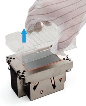
1. Remove the heatsink protective cover. As shown in Figure1-3, lift the cover straight up and away from the heatsink.
|
|
CAUTION: When you remove the protective cover from the heatsink, be careful not to touch the thermal grease on the heatsink. |
Figure1-3 Removing the protective cover
2. Install the retaining bracket onto the heatsink.
a. As shown in Figure1-4, align the alignment triangle on the retaining bracket with the cut-off corner of the heatsink.
b. Lower the bracket vertically down on the heatsink until the four corners of the bracket click into the four corners of the heatsink.
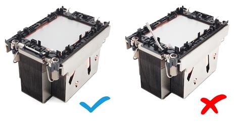
For the processor to be installed correctly, make sure the ejector lever on the retaining bracket is closed as shown in Figure1-5.
Figure1-4 Installing the processor onto the heatsink
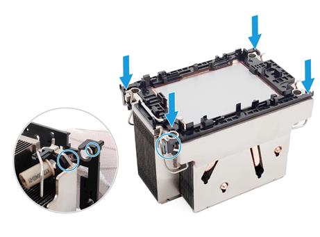
Figure1-5 Ejector lever status on the retaining bracket
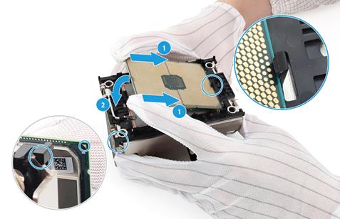
3. Install the processor onto the retaining bracket.
|
|
CAUTION: To avoid damage to a processor, always hold the processor by the edges. Never touch the gold contacts on the processor bottom. |
Figure1-6 Installing the processor onto the retaining bracket
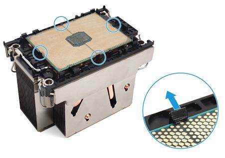
d. Open the retention clips on the retaining bracket to lock the processor in place.
Figure1-7 Locking the processor
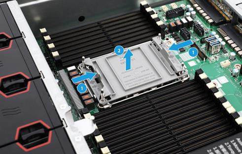
4. Remove the processor socket cover.
|
|
CAUTION: · Be careful not to touch the pins on the processor socket when you wear ESD gloves to remove the processor socket cover. · The pins on the processor socket are very fragile. Never touch the pins. Any damage to them might require system board replacement. · Keep the pins on the processor socket clean. Make sure the socket is free from dust and any other debris. |
As shown in Figure1-8, hold the cover by the tabs at both sides, and lift the cover straight up to remove it from the socket. Keep the cover secure for future use.
Figure1-8 Removing the processor socket cover
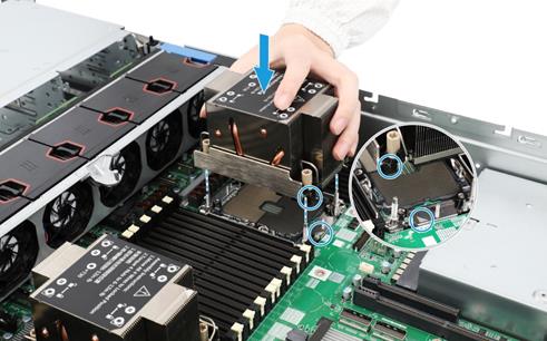
5. Install the heatsink onto the server.
a. Align the alignment triangle on the retaining bracket with the cut-off corner of the processor socket and the pin holes in the heatsink with the guide pins on the processor socket. Lower down the heatsink on the processor socket. See Figure1-9.
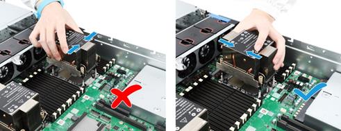
|
|
CAUTION: To avoid damages to the heatsink, hold the heatsink in the correct way as shown in Figure1-10. |
Figure1-9 Attaching the heatsink to the processor socket
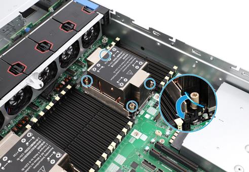
b. Press down the heatsink clips at the four corners to lock the heatsink in place.
Figure1-11 Locking the heatsink
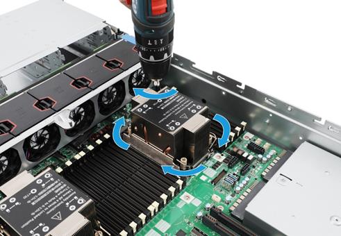
c. Use a T30 Torx screwdriver to fasten the four captive screws on the heatsink.
|
|
CAUTION: The screwdriver torque is in the range of 6 to 12 in-lb. As a best practice, use a torque of 8 in-lb to avoid poor contact of the processor or damage to the pins on the processor socket. |
Figure1-12 Fastening the captive screws
Installing DIMMs
After you install a new processor, install DIMMs for it. For the DIMM installation guidelines, see the server user guide.
To install a DIMM:
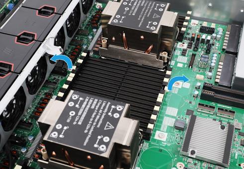
1. Open the retaining clips of the DIMM slot.
Figure1-13 Opening the retaining clips of the DIMM slot
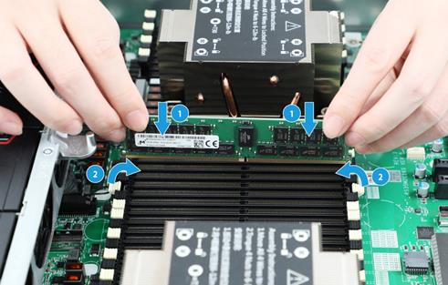
2. Align the notch on the DIMM bottom edge with the key on the DIMM slot.
3. Insert the DIMM into the slot and make sure the retaining clips lock the DIMM in place.
The DIMM slot has a structure that prevents misalignment. If you cannot insert the DIMM into the slot easily, the installation might be wrong. Re-orient the DIMM and then insert it into the slot again.
Figure1-14 Installing a DIMM
Starting the server
1. Install the chassis air baffle on the server. Align the notches on the air baffle with the pins on the chassis side panels, and then place the air baffle into the chassis.
Figure1-15 Installing the chassis air baffle
2. Install the access panel.
a. Place the access panel on top of the server chassis, with the guide pin in the chassis aligned with the pin hole in the locking lever area.
b. Close the locking lever. The access panel will automatically slide toward the server front to secure itself into place.
c. (Optional.) Lock the locking lever. Use a Phillips screwdriver to turn the screw on the lever 90 degree clockwise.
Figure1-16 Installing the access panel
3. Install the server into the rack.
4. Connect power cords for the server.
5. Power on the server.
