- Table of Contents
- Related Documents
-
| Title | Size | Download |
|---|---|---|
| 06-Web configuration examples | 1.02 MB |
Contents
System features configuration examples
Network settings configuration examples
Layer 2 static aggregation configuration example
Layer 2 dynamic aggregation configuration example
PPPoE client configuration example
MAC address table configuration example
Outbound dynamic NAT configuration example
Outbound static NAT configuration example
IPv4 static route configuration example
IPv6 static route configuration example
Static IPv6 address configuration example
DHCP server configuration example
DHCP relay agent configuration example
IPv4 static DNS configuration example
IPv4 dynamic DNS configuration example
IPv4 DNS proxy configuration example
IPv6 static DNS configuration example
IPv6 dynamic DNS configuration example
IPv6 DNS proxy configuration example
IGMP snooping configuration example
MLD snooping configuration example
Proxy ARP configuration example
Using the AP as a Stelnet server for password authentication configuration example
Network security configuration examples
ACL-based packet filter configuration example
Administrators configuration example
Network configuration examples
Wireless configuration examples
Radio management configuration example
WIPS device classification and countermeasures configuration example
WIPS malformed packet and flood attack detection configuration example
Signature-based attack detection configuration example
Client rate limiting configuration example
Bandwidth guarantee configuration example
Shared key authentication configuration example
PSK authentication and bypass authentication configuration example
PSK authentication and MAC authentication configuration example
802.1X RADIUS authentication configuration example
802.1X local authentication configuration example
802.1X AKM configuration example
Direct IPv4 portal authentication configuration example
Band navigation configuration example
Bonjour gateway configuration example
WLAN mesh configuration example
Multicast optimization configuration example
System features configuration examples
Network settings configuration examples
Layer 2 static aggregation configuration example
Network requirements
As shown in Figure 1, configure a Layer 2 static aggregation group on both the AP and switch to improve the link reliability.

Hardware and feature compatibility
|
Hardware series |
Model |
Feature compatibility |
|
WA6600 series |
WA6638 |
Yes |
|
WA6638i |
Yes |
|
|
WA6636 |
Yes |
|
|
WA6630X |
Yes |
|
|
WA6628 |
Yes |
|
|
WA6628X |
No |
|
|
WA6628E-T |
No |
|
|
WA6622 |
Yes |
|
|
WA6620 |
Yes |
|
|
WA6620X |
Yes |
|
|
WA6300 series |
WA6338 |
Yes |
|
WA6338-HI |
Yes |
|
|
WA6338-LI |
Yes |
|
|
WA6330 |
Yes |
|
|
WA6330-LI |
Yes |
|
|
WA6322 |
Yes |
|
|
WA6322H |
No |
|
|
WA6322H-HI |
Yes |
|
|
WA6322H-LI |
No |
|
|
WA6320 |
No |
|
|
WA6320-C |
No |
|
|
WA6320-D |
No |
|
|
WA6320-SI |
No |
|
|
WA6320H |
Yes |
|
|
WA6320H-LI |
Yes |
|
|
WA6320H-XEPON |
Yes |
|
|
WAP922 series |
WAP922E |
No |
|
WAP923 series |
WAP923 |
Yes |
Configuration procedure
This example only shows the configuration on the AP.
To configure static aggregation configuration on the AP:
1. Click the system view tab at the bottom of the page.
2. From the navigation tree, select Network Configuration > Network Interfaces.
3. Click the Link Aggregation tab.
4. Configure a Layer 2 aggregation group:
a. Add Layer 2 aggregation group 1.
b. Configure the aggregation mode as Static.
c. Assign ports GigabitEthernet 1/0/1 and GigabitEthernet 1/0/2 to the aggregation group.
Verifying the configuration
# Access the link aggregation page, and verify that ports GigabitEthernet 1/0/1 and GigabitEthernet 1/0/2 have been assigned to link aggregation group 1.
Layer 2 dynamic aggregation configuration example
Network requirements
As shown in Figure 2, configure a dynamic Layer 2 aggregation group on both the AP and switch to improve link reliability.

Hardware and feature compatibility
|
Hardware series |
Model |
Feature compatibility |
|
WA6600 series |
WA6638 |
Yes |
|
WA6638i |
Yes |
|
|
WA6636 |
Yes |
|
|
WA6630X |
Yes |
|
|
WA6628 |
Yes |
|
|
WA6628X |
No |
|
|
WA6628E-T |
No |
|
|
WA6622 |
Yes |
|
|
WA6620 |
Yes |
|
|
WA6620X |
Yes |
|
|
WA6300 series |
WA6338 |
Yes |
|
WA6338-HI |
Yes |
|
|
WA6338-LI |
Yes |
|
|
WA6330 |
Yes |
|
|
WA6330-LI |
Yes |
|
|
WA6322 |
Yes |
|
|
WA6322H |
No |
|
|
WA6322H-HI |
Yes |
|
|
WA6322H-LI |
No |
|
|
WA6320 |
No |
|
|
WA6320-C |
No |
|
|
WA6320-D |
No |
|
|
WA6320-SI |
No |
|
|
WA6320H |
Yes |
|
|
WA6320H-LI |
Yes |
|
|
WA6320H-XEPON |
Yes |
|
|
WAP922 series |
WAP922E |
No |
|
WAP923 series |
WAP923 |
Yes |
Configuration procedure
This example only shows the configuration on the AP.
To configure dynamic link aggregation on the AP:
1. Click the system view tab at the bottom of the page.
2. From the navigation tree, select Network Configuration > Network Interfaces.
3. Click the Link Aggregation tab.
4. Configure a Layer 2 aggregation group:
a. Add Layer 2 aggregation group 1.
b. Configure the aggregation mode as Dynamic.
c. Assign ports GigabitEthernet 1/0/1 and GigabitEthernet 1/0/2 to the aggregation group.
Verifying the configuration
# Access the link aggregation page, and verify that ports GigabitEthernet 1/0/1 and GigabitEthernet 1/0/2 have been assigned to link aggregation group 1.
PPPoE client configuration example
Network requirements
As shown in Figure 3, connect the fat AP to the Internet as a PPPoE client, and make sure the PC can telnet to the Web interface through interface VLAN-interface 10.

Configuration procedure
# Configure the PPPoE server to assign a username and password to the device. (Details not shown.)
# Configure the PPPoE client:
1. Click the system view tab at the bottom of the page.
2. From the navigation tree, select Network Configuration > Network Interfaces.
3. Click the PPPoE tab.
4. Click the ![]() icon.
icon.
5. Select the VLAN interface.
6. Enter the username and password, and select an online mode.
7. Select Open the NAT function.
8. Click Apply.
Verifying the configuration
# Configure static routes, and then verify that GigabitEthernet 1/0/1 has obtained an IP address through PPPoE dial-up.
MAC address table configuration example
Network requirements
As shown in Figure 4:
· Host at MAC address 000f-e235-dc71 is connected to interface GigabitEthernet 1/0/1 of the AP and belongs to VLAN 1.
· Client at MAC address 000f-e235-abcd, which behaved suspiciously on the network, also belongs to VLAN 1.
Configure the MAC address table as follows:
· To prevent MAC address spoofing, add a static entry for the host in the MAC address table of the AP.
· To drop all frames destined for the client, add a blackhole MAC address entry for the client.
· Set the aging timer to 500 seconds for dynamic MAC address entries.

Configuration procedures
1. Click the system view tab at the bottom of the page.
2. From the navigation tree, select Network Configuration > VLAN.
3. Click the MAC tab.
4. Add a static MAC address entry for MAC address 000f-e235-dc71 on GigabitEthernet 1/0/1 that belongs to VLAN 1.
5. Add a blackhole MAC address entry for MAC address 000f-e235-abcd that belongs to VLAN 1.
6. Access the advanced settings page to set the aging timer to 500 seconds for dynamic MAC address entries.
Verifying the configuration
# Access the Network Configuration > VLAN > MAC Address Table page to verify that a static and a blackhole MAC address entries have been created.
# Verify that the client cannot ping the host successfully.
MSTP configuration example
Network requirements
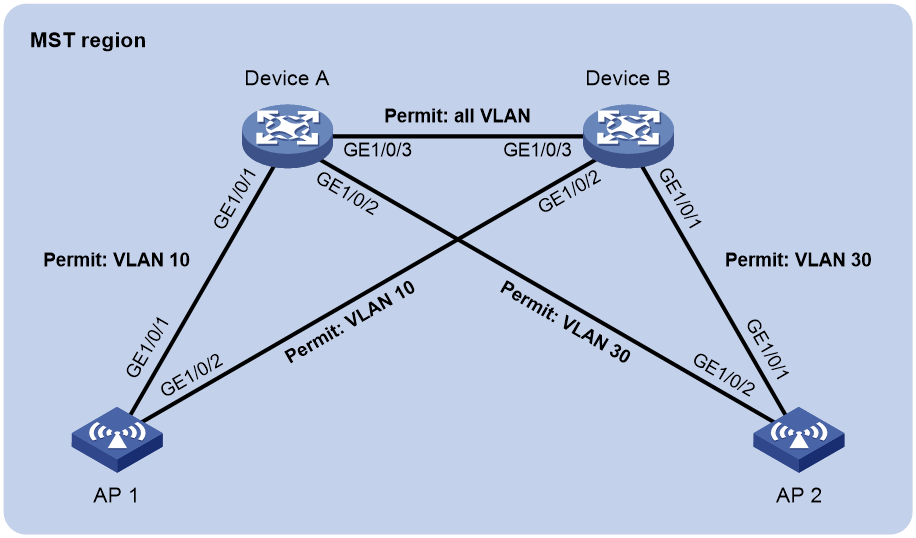
As shown in Figure 5, all devices in the network are in the same MST region. Device A and Device B operate at the distribution layer. AP 1 and AP 2 operate at the access layer.
Configure MSTP so that packets from different VLANs are forwarded along different spanning trees.
· Packets from VLAN 10 are forwarded along MSTI 1.
· Packets from VLAN 30 are forwarded along MSTI 2.
Configuration procedure
1. Configure VLANs:
a. Configure VLANs on Device A:
- Click the system view tab at the bottom of the page.
- From the navigation tree, select Network Configuration > VLAN. You are placed on the VLAN tab.
- Create VLAN 10 and VLAN 30.
- Access the details page for VLAN 10. Add ports GigabitEthernet 1/0/1 and GigabitEthernet 1/0/3 to the tagged port list.
- Access the details page for VLAN 30. Add ports GigabitEthernet 1/0/2 and GigabitEthernet 1/0/3 to the tagged port list.
b. Configure VLANs on Device B:
- Click the system view tab at the bottom of the page.
- From the navigation tree, select Network Configuration > VLAN. You are placed on the VLAN tab.
- Create VLAN 10 and VLAN 30.
- Access the details page for VLAN 10. Add ports GigabitEthernet 1/0/2 and GigabitEthernet 1/0/3 to the tagged port list.
- Access the details page for VLAN 30. Add ports GigabitEthernet 1/0/1 and GigabitEthernet 1/0/3 to the tagged port list.
c. Configure VLANs on AP 1:
- Click the system view tab at the bottom of the page.
- From the navigation tree, select Network Configuration > VLAN. You are placed on the VLAN tab.
- Create VLAN 10.
- Access the details page for VLAN 10. Add ports GigabitEthernet 1/0/1 and GigabitEthernet 1/0/2 to the tagged port list.
d. Configure VLANs on AP 2:
- Click the system view tab at the bottom of the page.
- From the navigation tree, select Network Configuration > VLAN. You are placed on the VLAN tab.
- Create VLAN 30.
- Access the details page for VLAN 30. Add ports GigabitEthernet 1/0/1 and GigabitEthernet 1/0/2 to the tagged port list.
2. Configure MSTP on Device A, Device B, AP 1, and AP 2:
a. Click the system view tab at the bottom of the page.
b. From the navigation tree, select Network Configuration > VLAN.
c. Click the STP tab.
d. Enable STP, and configure the operating mode as MSTP.
e. Access the MST region configuration page to perform the following tasks:
- Configure the MST region name as Web.
- Map VLAN 10 and VLAN 30 to MSTI 1 and MSTI 2, respectively.
- Set the MSTP revision level to 0.
Verifying the configuration
# Verify that the port roles and port states in the spanning tree status are as expected.
Outbound dynamic NAT configuration example
Network requirements
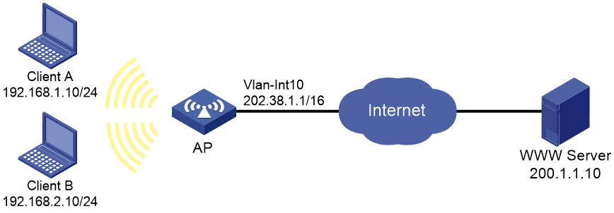
As shown in Figure 6, a company has a private address 192.168.0.0/16 and two public IP addresses 202.38.1.2 and 202.38.1.3. Configure outbound dynamic NAT to allow only internal users on subnet 192.168.1.0/24 to access the Internet.
Configuration procedures
1. Click the system view tab at the bottom of the page.
2. From the navigation tree, select Network Configuration > Network Services >NAT.
3. Click Dynamic NAT.
4. Click the add icon.
5. On the New Dynamic NAT Rule page, perform the following tasks:
a. Add ACL 2000 to permit packets only from subnet 192.168.1.0/24 to pass through.
b. Add address group 0, and add an address range from 202.38.1.2 to 202.38.1.3 to the group.
6. Apply the dynamic NAT rule to VLAN-interface 10.
Verifying the configuration
# Verify that Client A can access the WWW server, but Client B cannot. (Details not shown.)
Outbound static NAT configuration example
Network requirements
Configure static NAT to enable the client to access the WWW server on the external network.
Figure 7 Network diagram

Configuration procedure
1. Click the system view tab at the bottom of the page.
2. From the navigation tree, select Network Configuration > Network Services >NAT.
3. Click Static NAT.
4. Click the Rules tab.
5. Click the ![]() icon.
icon.
6. Select the Host to host translation mode.
7. Enter 192.168.1.10 in the private address field and 202.38.1.100 in the public address field.
8. Click Apply.
9. Click the Apply tab.
10. Select interface VLAN-interface 10.
11. Click Apply.
Verifying the configuration
# Verify that the client can access the WWW server on the external network.
IPv4 static route configuration example
Network requirements
As shown in Figure 8, configure IPv4 static routes for the client to communicate with the WWW server.

Configuration procedure
This example shows only the configuration on the AP:
To configure IPv4 static routes for the AP:
1. Click the system view tab at the bottom of the page.
2. From the navigation tree, select Network Configuration > Network Routing.
3. Click the Static Routing tab.
4. Click IPv4 static routing.
5. Configure the default route:
a. Set the destination IP address to 0.0.0.0.
b. Set the mask length to 0.
c. Set the next hop address to 192.168.2.2.
Verifying the configuration
# Verify that the client can access the WWW server. (Details not shown.)
IPv6 static route configuration example
Network requirements
As shown in Figure 9, configure IPv6 static routes for the client to communicate with the WWW server.

Configuration procedure
This example shows only the configuration on the AP.
To configure IPv6 static routes for the AP:
1. Click the system view tab at the bottom of the page.
2. From the navigation tree, select Network Configuration > Network Routing.
3. Click the Static Routing tab.
4. Click IPv6 static routing.
5. Configure the IPv6 default route:
a. Set the destination IP address to ::.
b. Set the mask length to 0.
c. Set the next hop address to 4::2.
Verifying the configuration
# Verify that the client can ping the WWW server. (Details not shown.)
Static IPv6 address configuration example
Network requirements
As shown in Figure 10, the client generates an IPv6 address through stateless address autoconfiguration.
Assign a global unicast IPv6 address to VLAN-interface 1 of the AP.

Configuration procedure
1. Configure basic functions on the AP. For more information about the configuration, see WLAN Configuration Guide. (Details not shown.)
2. Configure an IPv6 address for VLAN-interface 1:
a. Click the system view tab at the bottom of the page.
b. From the navigation tree, select Network Configuration > Network Services > IP Services.
c. Click the IPv6 tab.
d. Access the details page for VLAN-interface 1 to perform the following tasks:
- Configure the IPv6 address of the interface as 2001::1.
- Set the prefix length to 64.
3. Configure VLAN-interface 1 to advertise RA messages.
a. Click the system view tab at the bottom of the page.
b. From the navigation tree, select Network Configuration > Network Services > ND. You are placed on the ND tab.
c. Access the advanced settings page to configure the RA settings.
d. Configure VLAN-interface 1 to advertise RA messages.
4. Install IPv6 on the client. The client automatically generates an IPv6 address based on the address prefix information contained in the RA message.
Verifying the configuration
# Verify that the client and the AP can ping each other.
DHCP server configuration example
Network requirements
As shown in Figure 11, the DHCP server (AP) assigns IP addresses to the switch and DHCP clients on subnet 10.1.1.0/24, which is subnetted into 10.1.1.0/25 and 10.1.1.128/25. The AP is connected to the clients and the switch through two VLAN interfaces: VLAN-interface 10 at 10.1.1.1/25 and VLAN-interface 20 at 10.1.1.129/25.
Configure DHCP server on the AP to assign an IP address on subnet 10.1.1.0/25 to the switch and IP addresses on subnet 10.1.1.128/25 to DHCP clients.

Configuration procedure
1. Click the system view tab at the bottom of the page.
2. Configure VLANs and VLAN interfaces:
a. From the navigation tree, select Network Configuration > VLAN. You are placed on the VLAN tab.
b. Create VLANs and assign IP addresses to VLAN interfaces:
- Create VLAN 10 and assign IP address 10.1.1.1/25 to VLAN-interface 10.
- Create VLAN 20 and assign IP address 10.1.1.129/25 to VLAN-interface 20.
3. Configure the DHCP server:
a. From the navigation tree, select Network Configuration > Network Services > DHCP/DNS. You are placed on the DHCP tab.
b. Enable DHCP.
c. Specify VLAN-interface 10 and VLAN-interface 20 as DHCP servers.
d. Click the address pool link and perform the following tasks:
- Create the address pool pool1, specify 10.1.1.0/25 as the subnet for dynamic assignment, and specify 10.1.1.1 as the gateway.
- Create the address pool pool2, specify 10.1.1.128/25 as the subnet for dynamic assignment, and specify 10.1.1.129 as the gateway.
e. Access the advanced settings page to perform the following tasks:
- Set the maximum number of ping packets to 1.
- Set the ping response timeout time to 500 milliseconds.
4. Click the network view tab at the bottom of the page.
5. Configure a wireless service:
a. From the navigation tree, select Wireless Configuration > Wireless Networks.
b. Add a wireless service:
- Create a wireless service named service.
- Set the SSID to office.
- Specify the default VLAN 20.
- Enable the wireless service.
6. Configure the AP:
a. From the navigation tree, select Wireless Configuration > AP Management.
b. On the WLAN Service Settings tab, bind wireless service service to the 5 GHz radio of the AP.
7. Configure the AP radio:
a. From the navigation tree, select Wireless Configuration > Radio Management.
b. Set the status of the 5 GHz radio of the AP to On.
Verifying the configuration
1. Verify that the switch can obtain an IP address on subnet 10.1.1.0/25 and the gateway address from the DHCP server.
2. Verify that the DHCP clients can obtain IP addresses on subnet 10.1.1.128/25 and the gateway address from the DHCP server.
DHCP relay agent configuration example
Network requirements
As shown in Figure 12, the DHCP clients and the DHCP server are in different subnets. The DHCP clients reside in subnet 10.10.1.0/24 and the DHCP server is at 10.1.1.1/24. An AP is deployed between the DHCP clients and the DHCP server. The AP is connected to the network in which the DHCP clients reside through VLAN-interface 10 at 10.10.1.1/24. The AP is connected to the DHCP server through VLAN-interface 20 at 10.1.1.2/24.
Configure the DHCP relay agent on the AP, so the DHCP clients can obtain IP addresses and other configuration parameters from the DHCP server.

Configuration procedure
1. Assign IP addresses to interfaces. (Details not shown.)
2. Configure the DHCP server. (Details not shown.)
3. Configure basic settings on the AP. (Details not shown.)
4. Configure the DHCP relay agent:
a. Click the system view tab at the bottom of the page.
b. From the navigation tree, select Network Configuration > Network Services > DHCP/DNS. You are placed on the DHCP tab.
c. Perform the following tasks:
- Enable DHCP.
- Specify VLAN-interface 10 as the DHCP relay agent.
- Specify the DHCP server address 10.1.1.1.
Verifying the configuration
Verify that the DHCP clients can obtain IP addresses and other configuration parameters from the DHCP server through the DHCP relay agent.
IPv4 static DNS configuration example
Network requirements
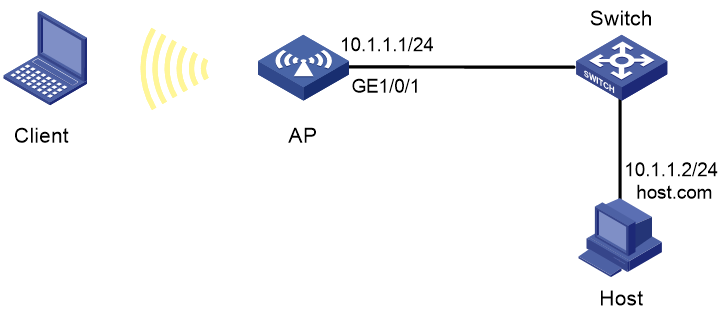
As shown in Figure 13, configure a static DNS entry on the AP, so the AP can use the domain name host.com to access the host at 10.1.1.2.
Configuration procedure
1. Click the system view tab at the bottom of the page.
2. From the navigation tree, select Network Configuration > Network Services > DHCP/DNS.
3. Click the IPv4 DNS tab.
4. Create a static DNS entry:
¡ Configure the host name as host.com.
¡ Configure the IPv4 address as 10.1.1.2.
Verifying the configuration
Use the ping host.com command on the AP to verify the following items:
· The ping operation succeeds.
· The AP can use static domain name resolution to resolve the domain name host.com into the IPv4 address 10.1.1.2.
IPv4 dynamic DNS configuration example
Network requirements
As shown in Figure 14, the DNS server at 2.1.1.2/16 has a com domain that stores the mapping between the domain name host and the IPv4 address 3.1.1.1/16.
Configure dynamic DNS and the DNS suffix com on the AP that acts as a DNS client. The AP can use the domain name host to access the host whose domain name is host.com and IPv4 address is 3.1.1.1/16.

Configuration procedure
1. Map the domain name host.com to the IPv4 address 3.1.1.1 on the DNS server. (Details not shown.)
2. Configure static routes or dynamic routing protocols on the devices to make sure the devices can reach each other. (Details not shown.)
3. Configure DNS client on the AP:
a. Click the system view tab at the bottom of the page.
b. From the navigation tree, select Network Configuration > Network Services > DHCP/DNS.
c. Click the IPv4 DNS tab.
d. Specify the DNS server address 2.1.1.2.
e. Access the advanced settings page and add the domain name suffix com.
Verifying the configuration
Use the ping host command on the AP to verify the following items:
· The ping operation succeeds.
· The AP can resolve the domain name host.com into the IPv4 address 3.1.1.1 through the DNS server.
IPv4 DNS proxy configuration example
Network requirements
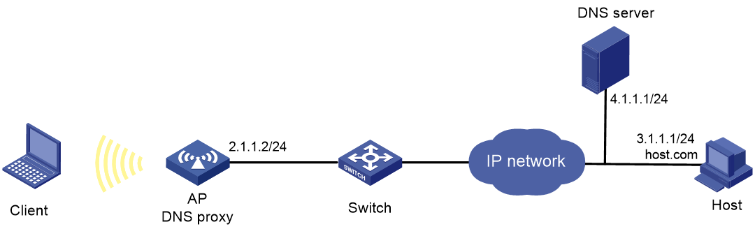
As shown in Figure 15, the LAN has a large number of devices deployed. The devices access the DNS server for domain name resolution. If the DNS server's IP address changes, the administrator must modify the DNS server address on each device, which takes a lot of time.
To simplify the configuration, configure the AP as the DNS proxy. Specify the real DNS server address on the AP. Specify the DNS proxy address as the DNS server address on the other devices. If the DNS server address changes, the administrator only needs to modify the DNS server address on the DNS proxy.
Configuration procedure
1. Configure static routes or dynamic routing protocols on the devices to make sure the devices can reach each other. (Details not shown.)
2. Configure the DNS server. (Details not shown.)
3. Configure DNS proxy on the AP:
a. Click the system view tab at the bottom of the page.
b. From the navigation tree, select Network Configuration > Network Services > DHCP/DNS.
c. Click the IPv4 DNS tab.
d. Specify the DNS server address 4.1.1.1.
e. On the advanced settings page, enable DNS proxy.
4. Configure DNS clients.
Specify the DNS proxy address 2.1.1.2 as the DNS server address on the other devices that act as DNS clients.
Verifying the configuration
Use the ping host.com command on a DNS client to verify the following items:
· The ping operation succeeds.
· The client can resolve the domain name host.com into the IPv4 address 3.1.1.1 through the DNS server.
IPv6 static DNS configuration example
Network requirements
As shown in Figure 16, configure a static DNS entry on the AP, so the AP can use the domain name host.com to access the host at 1::2.
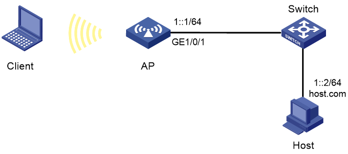
Configuration procedure
1. Click the system view tab at the bottom of the page.
2. From the navigation tree, select Network Configuration > Network Services > DHCP/DNS.
3. Click the IPv6 DNS tab.
4. Create a static DNS entry:
¡ Configure the host name as host.com.
¡ Configure the IPv6 address as 1::2.
Verifying the configuration
Use the ping ipv6 host.com command on the AP to verify the following items:
· The ping operation succeeds.
· The AP can use static domain name resolution to resolve the domain name host.com into the IPv6 address 1::2.
IPv6 dynamic DNS configuration example
Network requirements
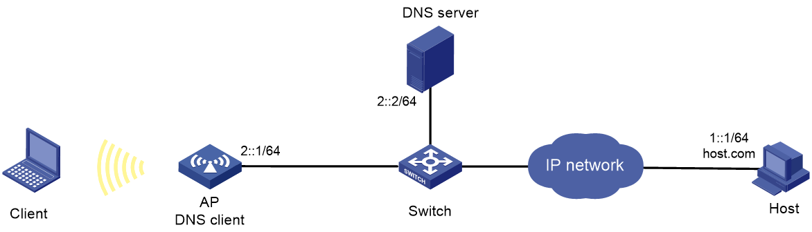
As shown in Figure 17, the DNS server at 2::2/64 has a com domain that stores the mapping between the domain name host and the IPv6 address 1::1/64.
Configure dynamic DNS and the DNS suffix com on the AP that acts as a DNS client. The AP can use the domain name host to access the host whose domain name is host.com and IPv6 address is 1::1/64.
Configuration procedure
1. Map the domain name host.com to the IPv6 address 1::1 on the DNS server. (Details not shown.)
2. Configure static routes or dynamic routing protocols on the devices to make sure the devices can reach each other. (Details not shown.)
3. Configure DNS client on the AP:
a. Click the system view tab at the bottom of the page.
b. From the navigation tree, select Network Configuration > Network Services > DHCP/DNS.
c. Click the IPv6 DNS tab.
d. Specify the DNS server address 2::2.
e. Access the advanced settings page and add the domain name suffix com.
Verifying the configuration
Use the ping ipv6 host command on the AP to verify the following items:
· The ping operation succeeds.
· The AP can resolve the domain name host.com into the IPv6 address 1::1 through the DNS server.
IPv6 DNS proxy configuration example
Network requirements
As shown in Figure 18, the LAN has a large number of devices deployed. The devices access the DNS server for domain name resolution. If the DNS server's IPv6 address changes, the administrator must modify the DNS server address on each device, which takes a lot of time.
To simplify the configuration, configure the AP as the DNS proxy. Specify the real DNS server address on the AP. Specify the DNS proxy address as the DNS server address on the other devices. If the DNS server address changes, the administrator only needs to modify the DNS server address on the DNS proxy.

Configuration procedure
1. Configure static routes or dynamic routing protocols on the devices to make sure the devices can reach each other. (Details not shown.)
2. Configure the DNS server. (Details not shown.)
3. Configure DNS proxy on the AP:
a. Click the system view tab at the bottom of the page.
b. From the navigation tree, select Network Configuration > Network Services > DHCP/DNS.
c. Click the IPv6 DNS tab.
d. Specify the DNS server address 4000::1.
e. On the advanced settings page, enable DNS proxy.
4. Configure DNS clients.
Specify the DNS proxy address 2000::2 as the DNS server address on the other devices that act as DNS clients.
Verifying the configuration
Use the ping ipv6 host.com command on a DNS client to verify the following items:
· The ping operation succeeds.
· The client can resolve the domain name host.com into the IPv6 address 3000::1 through the DNS server.
IGMP snooping configuration example
Network requirements
As shown in Figure 19:
· The network is a Layer 2-only network.
· The source sends multicast data to the multicast group 224.1.1.1, and the host is the receiver of the group.
· The host runs IGMPv2, and the AP acts as the IGMP querier.
Configure the devices to meet the following requirements:
· For IGMP snooping forwarding entries to be created, configure the source IP address of IGMP queries as a non-zero IP address on the AP.
· To prevent unknown multicast data from being flooded in VLAN 1, enable the devices to drop unknown multicast data.

Configuration procedure
1. Configure the AP:
a. Click the system view tab at the bottom of the page.
b. From the navigation tree, select Network Configuration > Network Services > Multicast. You are placed on the IGMP Snooping tab.
c. Enable IGMP snooping.
d. Access the page for enabling IGMP snooping on a VLAN to perform the following tasks:
- Set the VLAN ID to 1.
- Set the IGMP snooping version to 2.
- Enable dropping unknown multicast data.
- Enable the AP to act as the IGMP querier.
- Set the source IP address to 192.168.1.10 for IGMP general queries.
- Set the source IP address to 192.168.1.10 for IGMP group-specific queries.
2. Configure the switch:
# Enable IGMP snooping for VLAN 1, set the IGMP snooping version to 2, and then enable dropping unknown multicast data. (Details not shown.)
Verifying the configuration
1. Send IGMP reports from the host to join the multicast group 224.1.1.1. (Details not shown.)
2. Send multicast data from the source to the multicast group. (Details not shown.)
3. Access the Network Configuration> Network Services > Multicast > IGMP snooping > Entries page to verify that GigabitEthernet 1/0/1 and GigabitEthernet 1/0/2 are host ports of VLAN 1.
MLD snooping configuration example
Network requirements
As shown in Figure 20:
· The network is a Layer 2-only network.
· The source sends IPv6 multicast data to the IPv6 multicast group FF1E::101. The host is the receiver of the group.
· The host runs MLDv1, and the AP acts as the MLD querier.
To prevent unknown IPv6 multicast data from being flooded in VLAN 1, enable all the devices to drop unknown IPv6 multicast data.

Configuration procedure
1. Configure the AP:
a. Click the system view tab at the bottom of the page.
b. From the navigation tree, select Network Configuration > Network Services > Multicast. You are placed on the IGMP Snooping tab.
c. Click the MLD Snooping tab, and then enable MLD snooping.
d. Access the page for enabling MLD snooping on a VLAN to perform the following tasks:
- Set the VLAN ID to 1.
- Set the MLD snooping version to 1.
- Enable dropping unknown IPv6 multicast data.
- Enable the AP to act as an MLD querier.
- Apply the configuration.
2. Configure the switch:
# Enable MLD snooping for VLAN 1, set the MLD snooping version to 1, and then enable dropping unknown IPv6 multicast data. (Details not shown.)
Verifying the configuration
1. Send MLD reports from the host to join the IPv6 multicast group FF1E::101. (Details not shown.)
2. Send IPv6 multicast data from the source to the IPv6 multicast group. (Details not shown.)
3. Verify that MLD snooping forwarding entries of the IPv6 multicast group exist.
Proxy ARP configuration example
Network requirements
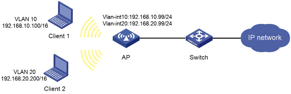
As shown in Figure 21, Client 1 and Client 2 have the same IP prefix and mask, but they are located on different subnets separated by the AP. Client 1 belongs to VLAN 10, and Client 2 belongs to VLAN 20. No default gateway is configured on Client 1 and Client 2.
Configure proxy ARP on the AP to enable communication between the two clients.
Configuration procedure
1. Configure VLAN 10 and VLAN 20, and assign IP addresses to VLAN-interface 10 and VLAN-interface 20:
a. Click the system view tab at the bottom of the page.
b. From the navigation tree, select Network Configuration > VLAN. You are placed on the VLAN tab.
c. Create VLAN 10, and assign IP address 192.168.10.99/24 to VLAN-interface 10.
d. Create VLAN 20, and assign IP address 192.168.20.99/24 to VLAN-interface 20.
2. Enable proxy ARP on VLAN-interface 10 and VLAN-interface 20.
a. Click the system view tab at the bottom of the page.
b. From the navigation tree, select Network Configuration > Network Services > ARP. You are placed on the ARP tab.
c. Access the advanced settings page to configure proxy ARP.
- Enable proxy ARP on VLAN-interface 10.
- Enable proxy ARP on VLAN-interface 20.
Verifying the configuration
# Verify that Client 1 and Client 2 can ping each other.
Using the AP as a Stelnet server for password authentication configuration example
Network requirements
As shown in Figure 22:
· The host and the AP can reach each other.
· The AP acts as a Stelnet server and uses password authentication.
· The username and password of the client are saved on the AP.
Establish a Stelnet connection between the host and the AP, so you can log in to the AP to configure and manage it.

Configuration procedure
1. Configure the Stelnet server:
a. Click the system view tab at the bottom of the page.
b. From the navigation tree, select Network Configuration > Management Protocols.
c. Click the SSH tab.
d. Enable the Stelnet service.
2. Configure the VLAN interface:
a. Click the system view tab at the bottom of the page.
b. From the navigation tree, select Network Configuration > VLAN.
c. On the VLAN tab, create VLAN 2.
d. Click the edit icon for VLAN 2.
The Edit VLAN page opens.
e. Add GigabitEthernet 1/0/2 to the untagged port list.
f. Select Configure VLAN interface.
g. Set the IPv4 address/mask to 192.168.1.40/24.
3. Configure the administrator account:
a. Click the system view tab at the bottom of the page.
b. From the navigation tree, select System > Administrators.
c. Click the add icon.
d. Set the username and password to client and hello12345, respectively.
e. Select network-admin from the user roles list.
f. Select SSH for the permitted access types parameter.
Verifying the configuration
This example uses PuTTY0.58 to verify the configuration.
1. Execute PuTTY on the host.
2. Enter 192.168.1.40 in the Host Name (or IP address) field.
3. Click Open.
4. Verify that you can use username client and password hello12345 to log in to the configuration page of the AP.
NTP configuration example
Network requirements
As shown in Figure 23:
· Configure the local clock of AP 1 as a reference source, with the stratum level 2.
· Set AP 2 to client mode and use AP 1 as the NTP server for AP 2.

Configuration procedure
1. Configure AP 1 (NTP server):
a. Click the system view tab at the bottom of the page.
b. From the navigation tree, select Network Configuration > Management Protocols.
c. Click the NTP tab.
d. Enable the NTP service.
e. Specify the IP address of the local clock as 127.127.1.0.
f. Configure the stratum level of the local clock as 2.
2. Configure AP 2:
a. Click the system view tab at the bottom of the page.
b. From the navigation tree, select System > Management. You are placed on the Settings tab.
c. Select automatic time synchronization with a trusted time source, and then select NTP as the time protocol.
d. Specify the IP address of Device A as 1.0.1.11, and configure Device B to operate in server mode.
Verifying the configuration
# Verify that AP 2 has synchronized to AP 1, and the clock stratum level is 3 on AP 2 and 2 on AP 1.
LLDP configuration example
Network requirements
As shown in Figure 24, configure LLDP on the AP and switch to meet the following requirements:
· The AP can discover the switch and obtain system and configuration information from the switch.
· The switch cannot discover the AP.

Configuration procedure
1. Configure LLDP on the AP:
a. Click the system view tab at the bottom of the page.
b. From the navigation tree, select Network Configuration > Management Protocols.
c. Click the LLDP tab.
d. Enable LLDP globally.
e. Access the interface status page, and then enable LLDP on GigabitEthernet 1/0/1.
f. Access the interface configuration page to perform the following tasks:
- Enable the nearest bridge agent function on GigabitEthernet 1/0/1.
- Set the operating mode of the interface to Rx mode to configure the interface to only receive LLDP frames.
Then, the AP can discover neighbors.
2. Configure LLDP on the switch:
a. Click the system view tab at the bottom of the page.
b. From the navigation tree, select Network Configuration > Management Protocols > LLDP.
c. Enable LLDP globally on the switch.
d. Access the interface status page, and then enable LLDP on GigabitEthernet 1/0/2.
e. Access interface configuration page to perform the following tasks:
- Enable the nearest bridge agent function on GigabitEthernet 1/0/2.
- Set the operating mode of the interface to Tx mode to configure the interface to only transmit LLDP frames.
Then, the switch cannot discover neighbors.
Verifying the configuration
1. Verify that you can view information about the switch on the LLDP neighbor information page of the AP.
2. Verify that the LLDP neighbor information page of the switch does not contain an entry for the AP.
Network security configuration examples
ACL-based packet filter configuration example
Network requirements
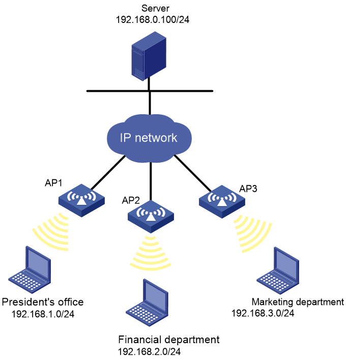
As shown in Figure 25, a company interconnects its departments through the APs. Configure the packet filter on the APs to meet the following requirements:
· Permit access from the President's office at any time to the financial database server.
· Permit access from the Financial Department to the financial database server only during working hours (from 8:00 to 18:00) on working days.
· Deny access from any other department to the financial database server.
Configuration procedure
1. Click the system view tab at the bottom of the page.
2. From the navigation tree, select Network Security > Packet Filter.
3. Create a packet filter policy:
a. Select interface GE1/0/1.
b. Select the outbound application direction.
c. Select the IPv4 ACL type for packet filter.
4. Create an advanced IPv4 ACL and configure the following rules in the order they are described:
|
Action |
Protocol type |
IP/wildcard mask |
Time range |
|
Permit |
256 |
Source: 192.168.1.0/0.0.0.255 Destination: 192.168.0.100/0 |
N/A |
|
Permit |
256 |
Source: 192.168.2.0/0.0.0.255 Destination: 192.168.0.100/0 |
Create a time range named work: · Specify the start time as 08:00. · Specify the end time as 18:00. · Select Monday through Friday. |
|
Deny |
256 |
Destination: 192.168.0.100/0 |
N/A |
5. Enable rule match counting for the ACL.
Verifying the configuration
1. Ping the database server from different departments to verify the following items:
¡ You can access the server from the President's office at any time.
¡ You can access the server from the Financial Department during the working hours on working days.
¡ You cannot access the server from the Marketing Department at any time.
2. Access the ACL rule Web interface, verify that the ACL rules are active and the number of matching packets is displayed.
System configuration examples
Administrators configuration example
Network requirements
As shown in Figure 26, configure an administrator account with the username webuser and password hello12345 on the AP to meet the following requirements:
· Allow the user to use the account to log in to the AP through HTTP.
· Perform local authentication for the user that uses the administrator account to log in to the AP.
· Assign the network-admin user role to the authenticated user.

Configuration procedure
1. Click the system view tab at the bottom of the page.
2. Configure the VLAN and VLAN interface:
a. From the navigation tree, select Network Configuration > VLAN. You are placed on the VLAN tab.
b. Create VLAN 2.
c. Access the edit page for VLAN 2 to perform the following tasks:
- Add the interface that connects to the admin's PC to the tagged port list.
- Create VLAN-interface 2.
- Assign the IP address 192.168.1.20/24 to VLAN-interface 2.
3. Configure an administrator account:
a. From the navigation tree, select System > Administrators. You are placed on the Administrators tab.
b. Create and configure an administrator account:
- Set the username and the password to webuser and hello12345, respectively.
- Select the network-admin user role.
- Specify HTTP and HTTPS as the permitted access types.
Verifying the configuration
1. Access the System > Administrators page to verify that the administrator account is successfully added.
2. Enter http://192.168.1.20 in the address bar to verify the following items:
¡ You can use the administrator account to log in to the Web interface.
¡ After login, you can configure the device.
Network configuration examples
Wireless configuration examples
Radio management configuration example
Network requirements
As shown in Figure 27, perform the following tasks to configure the 5 GHz radio of the AP:
· Set the radio type, working channel, and maximum transmit power for radio 1 to 802.11ac, 153, and 18 dBm, respectively.
· Set the radio type, working channel, and maximum transmit power for radio 2 to 802.11ac, 48, and 19 dBm, respectively.
· Set the maximum mandatory NSS, maximum supported NSS, multicast NSS, and VHT-MCS index to 2, 3, 2, and 5, respectively.
· Enable the A-MSDU and A-MPDU aggregation methods to improve network throughput.

Configuration procedure
1. Click the network view tab at the bottom of the page.
2. From the navigation tree, select Wireless Configuration > Radio Management. You are placed on the Radio Configuration tab.
3. Click the edit icon in the operation column for the 5 GHz radio of the AP. You are placed on the Basic tab.
4. Perform the following tasks in the basic configuration area:
a. Enable radios 1 and 2.
b. Set the radio type to 802.11ac (5GHz) for both radios.
c. Set the channel to 153 for radio 1 and 48 for radio 2.
d. Set the maximum transmit power to 18 dBm for radio 1 and 19 dBm for radio 2.
5. Perform the following tasks in the rates configuration area:
a. Set the maximum mandatory NSS to 2.
b. Set the maximum supported NSS to 3.
c. Set the multicast NSS to 2.
d. Set the VHT-MCS index to 5.
6. Perform the following tasks in the 802.11n/802.11ac configuration area:
a. Enable the A-MSDU aggregation method.
b. Enable the A-MPDU aggregation method.
7. Apply the configuration.
Verifying the configuration
# Access the Wireless Configuration > Radio Management > Radio Configuration page to verify that the configuration is correct.
WIPS device classification and countermeasures configuration example
Network requirements
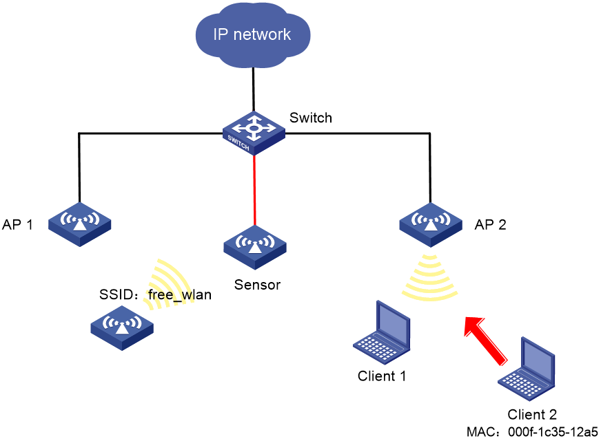
As shown in Figure 28, AP 1 and AP 2 provide wireless services to clients through the SSID abc. Perform the following tasks:
· Enable WIPS for the sensor.
· Configure wireless device classification to add the MAC address 000f-1c35-12a5 to the static prohibited device list and the SSID abc to the trusted SSID list.
· Configure countermeasures to enable WIPS to take countermeasures against potential-external APs and unauthorized clients.
Configuration procedure
1. Click the network view tab at the bottom of the page.
2. From the navigation tree, select Wireless Configuration > Wireless Security > WIPS.
3. Click the VSD tab and then click the plus icon + to create VSD VSD_1.
4. Click the WIPS Enable tab, enable WIPS for the AP, and add the AP to VSD VSD_1.
5. Click the Classification tab and perform the following tasks:
a. Create classification policy class1.
b. Add the MAC address of Client 2 to the prohibited device list.
c. Add SSID abc to the trusted SSID list.
6. Click the Countermeasure tab and perform the following tasks:
a. Create countermeasure policy protect.
b. Configure WIPS to take countermeasures against unauthorized clients and potential-external APs.
7. Click the VSD tab and perform the following tasks:
a. Apply classification policy class1 to VSD VSD_1.
b. Apply countermeasure policy protect to VSD VSD_1.
Verifying the configuration
# Verify that the AP with the MAC address 000f-e223-1616 is classified as a potential-external AP and the client with the MAC address 000f-1c35-12a5 is classified as an unauthorized client.
# Verify that WIPS has taken countermeasures against the unauthorized client with the MAC address 000f-1c35-12a5 and the potential-external AP with the MAC address 000f-e223-1616.
WIPS malformed packet and flood attack detection configuration example
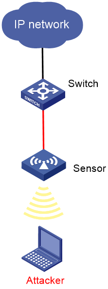
Network requirements
As shown in Figure 29, configure the AP as a sensor. Add the sensor to the VSD VSD_1. Configure malformed packet detection and flood attack detection to enable WIPS to trigger an alarm when it detects beacon flood attacks or malformed packets with duplicated IE.
Configuration procedure
1. Click the network view tab at the bottom of the page.
2. From the navigation tree, select Wireless Configuration > Wireless Security > WIPS.
3. Click the VSD tab, and then click the plus sign + to create VSD VSD_1.
4. Click the WIPS Enable tab, enable WIPS for the AP, and add the AP to VSD VSD_1.
5. Click the Detection tab and perform the following tasks:
a. Create an attack detection policy.
b. Enable detection on malformed packets with duplicated IE, and set the quiet time to 50 seconds.
c. Enable beacon flood attack detection, and set the statistics interval, threshold, and quiet time to 100 seconds, 200, and 50 seconds, respectively.
6. Click the VSD tab and apply the attack detection policy to VSD VSD_1.
Verifying the configuration
# Verify that no malformed packets or flood attack messages exist when WIPS does not detect any attacks in the WLAN.
# Verify that the number of malformed packets or flood attack messages is not zero when WIPS detects beacon flood attacks and malformed packets with duplicated IE.
Signature-based attack detection configuration example
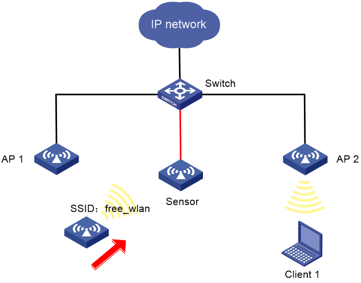
Network requirements
As shown in Figure 30, AP 1 and AP 2 provide wireless services for clients through the SSID abc. Enable WIPS for the sensor, and configure a signature to enable WIPS to trigger an alarm when it detects beacon frames whose SSIDs are not abc.
Configuration procedure
1. Click the network view tab at the bottom of the page.
2. From the navigation tree, select Wireless Configuration > Wireless Security > WIPS.
3. Click the VSD tab, and then click the plus sign + to create the VSD vsd1.
4. Click the WIPS Enable tab, and then enable WIPS for the AP and add the AP to VSD vsd1.
5. Click the Signature rule tab and perform the following tasks:
a. Create signature 1.
b. Configure a subsignature to match beacon frames.
c. Configure a subsignature to match frames whose SSIDs are not abc.
6. Click the Signature tab and perform the following tasks:
a. Create a signature policy named sig1.
b. Bind signature 1 to signature policy sig1.
c. Set the statistics collection interval, quiet time, and alarm threshold to 5 seconds, 60 seconds, and 60, respectively.
7. Click the VSD tab and apply signature policy sig1 to VSD vsd1.
Verifying the configuration
# Verify that WIPS generates an alarm when the sensor detects the wireless service with the SSID free_wlan.
Client rate limiting configuration example
Network requirements
As shown in Figure 31, perform the following tasks on the AP:
· Configure static mode client rate limiting to limit the rate of incoming client traffic.
· Configure dynamic mode client rate limiting to limit the rate of outgoing client traffic.
Configuration procedure
1. Click the network view tab at the bottom of the page.
2. Configure a wireless service:
a. From the navigation tree, select Wireless Configuration > Wireless Networks.
b. Add a wireless service:
- Create a wireless service named service.
- Set the SSID to service.
- Enable the wireless service.
3. Configure the AP:
a. From the navigation tree, select AP Management.
b. On the WLAN Service Settings tab, bind wireless service service to radio 1 of the AP.
4. Configure client rate limiting:
a. From the navigation tree, select Wireless Configuration > Wireless QoS. You are placed on the Client Rate Limiting tab.
b. Click the more icon in the service configuration area.
c. Select the service name service, and click the edit icon for the wireless service service.
d. On the edit page, perform the following tasks:
- Enable client rate limiting.
- Set the limit mode to static mode for inbound traffic.
- Set the per-client limit rate to 8000 for inbound traffic.
- Set the limit mode to dynamic mode for outbound traffic.
- Set the total limit rate to 8000 for outbound traffic.
5. Enable radio 1 of the AP:
a. From the navigation tree, select Wireless Configuration > Radio Management.
b. Enable radio 1 of the AP.
Bandwidth guarantee configuration example
Network requirements
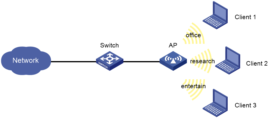
As shown in Figure 32, Clients 1, 2, and 3 access the network through the SSIDs research, office, and entertain, respectively.
For the network to operate correctly, guarantee 20% of the bandwidth for the SSID office, 80% for research, and none for entertain.
Configuration procedure
1. Click the network view tab at the bottom of the page.
2. Configure a wireless service:
a. From the navigation tree, select Wireless Configuration > Wireless Networks.
b. Add wireless services:
- Create wireless services named office, research, and entertain.
- Set their SSID to office, research, and entertain, respectively.
- Enable the wireless services.
3. Configure the AP:
a. From the navigation tree, select AP Management.
b. On the WLAN Service Settings tab, bind wireless services office, research, and entertain to radio 1 of the AP.
4. Configure bandwidth guaranteeing:
a. From the navigation tree, select Wireless Configuration > Wireless QoS.
b. Click the Bandwidth Guaranteeing tab.
c. Enable bandwidth guaranteeing.
d. Set the guaranteed bandwidth percentage to 20% for the wireless service office.
e. Set the guaranteed bandwidth percentage to 80% for the wireless service research.
5. Enable radio 1 of the AP:
a. From the navigation tree, select Wireless Configuration > Radio Management.
b. Enable radio 1 of the AP.
Verifying the configuration
# View details about AP configuration to verify that the effective bandwidth percentage for each SSID is not greater than the guaranteed bandwidth percentage.
Shared key authentication configuration example
Network requirements
As shown in Figure 33, configure shared key authentication to enable the client to access the network by using the WEP key 12345.

Configuration procedure
1. Click the network view tab at the bottom of the page.
2. Configure a wireless service:
a. From the navigation tree, select Wireless Configuration > Wireless Networks.
b. Add a wireless service:
- Create a wireless service named service1.
- Set the SSID to service.
- Enable the wireless service.
3. Click Apply and Set Advanced, and then click the Authentication tab.
4. Configure static WEP authentication:
¡ Set the security type to static WEP.
¡ Set the key type to Passphrase.
¡ Select the WEP 40 cipher suite.
¡ Set the key to 12345.
5. Apply the wireless service.
6. Bind the wireless service service1 to the 5 GHz radio:
a. From the navigation tree, select Wireless Configuration > Wireless Networks.
b. Select service1 and click Bind to Radio.
c. Select the 5GHz radio of the AP and click Bind.
Verifying the configuration
View details about the wireless service service1 to verify that the configuration is correct.
PSK authentication and bypass authentication configuration example
Network requirements
As shown in Figure 34, configure open system authentication and bypass authentication, and configure the client to use the preshared key 12345678 to access the network.

Configuration procedure
1. Click the network view tab at the bottom of the page.
2. Configure a wireless service:
a. From the navigation tree, select Wireless Configuration > Wireless Networks.
b. Add a wireless service:
- Create a wireless service named service1.
- Set the SSID to service.
- Enable the wireless service.
3. Click Apply and Set Advanced, and then click the Authentication tab.
4. Configure static PSK authentication:
¡ Set the security type to static PSK.
¡ Set the security mode to WPA.
¡ Select the CCMP cipher suite.
¡ Set the key type to Passphrase and the key to 12345678.
5. Apply the wireless service.
6. Bind the wireless service service1 to the 5 GHz radio:
a. From the navigation tree, select Wireless Configuration > Wireless Networks.
b. Select service1 and click Bind to Radio.
c. Select the 5GHz radio of the AP and click Bind.
Verifying the configuration
View details about the wireless service service1 to verify that the configuration is correct.
PSK authentication and MAC authentication configuration example
Network requirements
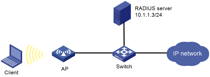
As shown in Figure 35, configure open system authentication and MAC authentication for clients, and configure the client to use the preshared key 12345678 to access the network.

Configuration procedure
1. On the RADIUS server, configure the client's MAC address as the username and password used for authentication. The MAC address cannot contain hyphens and upper case letters.
2. Configure the RADIUS server correctly to provide authentication, authorization, and accounting functions.
3. Configure RADIUS and an authentication domain.
4. Click the network view tab at the bottom of the page.
5. Configure a wireless service:
a. From the navigation tree, select Wireless Configuration > Wireless Networks.
b. Add a wireless service:
- Create a wireless service named service1.
- Set the SSID to service.
- Enable the wireless service.
6. Click Apply and Set Advanced, and then click the Authentication tab.
7. Configure static PSK authentication and MAC authentication:
¡ Set the security type to static PSK and select MAC authentication.
¡ Set the security mode to WPA.
¡ Select the CCMP cipher suite.
¡ Set the key type to Passphrase and the key to 12345678.
¡ Set the domain name to dom1.
8. Apply the wireless service.
9. Bind the wireless service service1 to the 5 GHz radio:
a. From the navigation tree, select Wireless Configuration > Wireless Networks.
b. Select service1 and click Bind to Radio.
c. Select the 5GHz radio of the AP and click Bind.
Verifying the configuration
View details about the wireless service service1 to verify that the configuration is correct.
802.1X RADIUS authentication configuration example
Network requirements
As shown in Figure 36, configure the AP to meet the following requirements:
· Use the RADIUS server to perform authentication, authorization, and accounting for 802.1X users.
· Authenticate all 802.1X users in the ISP domain dm1X.
· Exclude domain names from the usernames sent to the RADIUS server.
· Use name as the authentication and accounting shared keys for secure RADIUS communication between the AP and the RADIUS server.
· Use ports 1812 and 1813 for authentication and accounting, respectively.
Configuration procedure
1. Assign an IP address to each interface, as shown in Figure 36. (Details not shown.)
2. Click the system view tab at the bottom of the page.
3. Configure a RADIUS scheme on the AP:
a. From the navigation tree, select Network Security > Authentication.
b. Click the RADIUS tab.
c. Add and configure a RADIUS scheme:
- Set the name of the RADIUS scheme to 802.1X.
- Configure the primary authentication server: set its IP address to 10.1.1.1, set the port number to 1812, set the shared key to name, and set the state to Active.
- Configure the primary accounting server: set its IP address to 10.1.1.1, set the port number to 1813, set the shared key to name, and set the state to Active.
- Set the format of usernames sent to the RADIUS server to Excludes the domain name.
4. Configure an ISP domain on the AP:
a. Click the ISP domains tab.
b. Add and configure an ISP domain:
- Set the domain name to dm1X.
- Set the ISP domain state to Active.
- Set the service type to LAN access.
- Set the method and scheme for authentication, authorization, and accounting to RADIUS and 802.1X, respectively.
5. Configure 802.1X on the AP:
a. From the navigation tree, select Access Control. You are placed on the 802.1X tab.
b. Enable 802.1X globally.
c. Enable 802.1X on GigabitEthernet 1/0/1, and specify MAC-based access control.
d. Access the advanced settings configuration page for GigabitEthernet 1/0/1 to perform the following tasks:
- Set the authorization state to Auto.
- Set the mandatory authentication domain to dm1X.
6. Configure the RADIUS server:
¡ Add a user account on the server. (Details not shown.)
¡ Configure the authentication, authorization, and accounting settings. (Details not shown.)
Verifying the configuration
1. Access the Network Security > Authentication > RADIUS page to verify brief information of the RADIUS scheme 802.1X.
2. Access the Network Security > Authentication > ISP Domains page to verify brief information of the ISP domain dm1X.
3. Verify that the use can come online:
a. Use the configured username and password to log in.
b. Access the Network Security > Access Control > 802.1X page to verify that the number of online users is 1 on GigabitEthernet 1/0/1.
802.1X local authentication configuration example
Network requirements
As shown in Figure 37, add a user account with the username dotuser and password 12345 on the AP. Configure the AP to meet the following requirements:
· Perform local 802.1X authentication to control the network access of users on GigabitEthernet 1/0/1.
· Authenticate the users in the ISP domain abc.
· Specify port-based access control on GigabitEthernet 1/0/1. After a user passes authentication on the port, all subsequent users can access the network without authentication.

Configuration procedure
1. Assign an IP address to each interface, as shown in Figure 37. (Details not shown.)
2. Click the system view tab at the bottom of the page.
3. Configure a local user:
a. From the navigation tree, select Network Security > User Management. You are placed on the Local Users tab.
b. Add and configure a local user:
- Set the username to dotuser.
- Set the password to 12345.
- Set the service type to LAN access.
4. Configure an ISP domain:
a. From the navigation tree, select Authentication. You are placed on the ISP Domains tab.
b. Add and configure an ISP domain:
- Set the ISP domain name to abc.
- Set the ISP domain state to Active.
- Set the service type to LAN access.
- Configure the ISP domain to use local method for authentication and authorization of LAN users, and not perform accounting for LAN users.
5. Configure 802.1X:
a. From the navigation tree, select Access Control. You are placed on the 802.1X tab.
b. Enable 802.1X globally.
c. Enable 802.1X on GigabitEthernet 1/0/1, and specify port-based access control.
d. Access the advanced settings configuration page for GigabitEthernet 1/0/1 to perform the following tasks:
- Set the authorization state to Auto.
- Set the mandatory authentication domain to abc.
Verifying the configuration
1. Access the Network Security > User Management > Local Users page to verify the configuration of the local user dotuser.
2. Access the Network Security > Authentication > ISP Domains page to verify brief information of the ISP domain abc.
3. Verify that the use can come online:
a. Use the configured username and password to log in.
b. Access the Network Security > Access Control > 802.1X page to verify that the number of online users is 1 on GigabitEthernet 1/0/1.
802.1X AKM configuration example
Network requirements
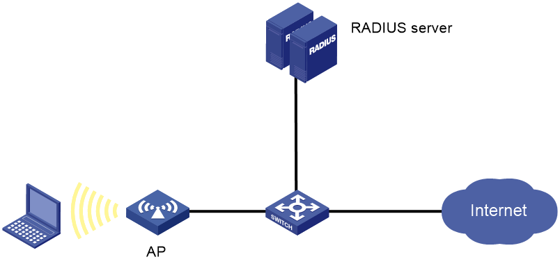
As shown in Figure 38, the switch functions as a DHCP server to assign IP addresses to the AP and client.
· Configure open system authentication and 802.1X authentication so that the client can access the network by using the login username abcdef and password 123456.
· Configure 802.1X as the AKM mode.
Configuration procedure
1. Configure the username abcdef and the password 123456 on the RADIUS server and make sure the RADIUS server and AP can reach each other. (Details not shown.)
2. Configure RADIUS and an authentication domain.
3. Click the network view tab at the bottom of the page.
4. Configure a wireless service:
a. From the navigation tree, select Wireless Configuration > Wireless Networks.
b. Add a wireless service:
- Create a wireless service named service1.
- Set the SSID to service.
- Enable the wireless service.
5. Click Apply and Set Advanced, and then click the Authentication tab.
6. Configure 802.1X authentication:
¡ Set the security type to 802.1X authentication.
¡ Set the security mode to WPA.
¡ Select the CCMP cipher suite.
¡ Set the domain name to dom1.
7. Apply the wireless service.
8. Bind the wireless service service1 to a radio:
a. From the navigation tree, select Wireless Configuration > Wireless Networks.
b. Select service1 and click Bind to Radio.
c. Select the target radio and click Bind.
Verifying the configuration
# View details about the wireless service service1 to verify that the configuration is correct.
Direct IPv4 portal authentication configuration example
Network requirements
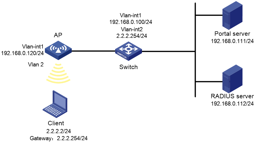
As shown in Figure 39, the AP directly forwards user traffic from the client. The client is assigned with a public IP address either manually or through DHCP. A portal server acts as both a portal authentication server and a portal Web server. A RADIUS server acts as the authentication/accounting server.
Configure direct portal authentication, so the client can access only the portal Web server before passing the authentication and access Internet resources after passing the authentication.
Configuration procedures
1. Configure IP addresses for the client, AP, and servers as shown in Figure 39 and make sure they can reach each other.
2. Configure the RADIUS server correctly to provide authentication and accounting functions.
3. Configure RADIUS and an authentication domain.
4. Configure a wireless service:
a. From the navigation tree, select Wireless Configuration > Wireless Networks.
b. Add a wireless service:
- Create a wireless service named service1.
- Set the SSID to service.
- Enable the wireless service.
5. Configure the portal authentication mode:
a. Click the edit icon for wireless service service1.
The advanced settings page opens.
b. Click the Authentication tab.
c. Select With IPv4 Portal Authentication.
d. Set the domain name to dm1.
e. Set the server URL to newpt.
f. Set the BAS-IP to 192.168.0.110.
g. Click Apply.
6. Bind the wireless service service1 to a radio:
a. From the navigation tree, select Wireless Configuration > Wireless Networks.
b. Select service1 and click Bind to Radio.
c. Select the target radio and click Bind.
Verifying the configuration
# View details about the service service1 to verify that the configuration is correct.
Band navigation configuration example
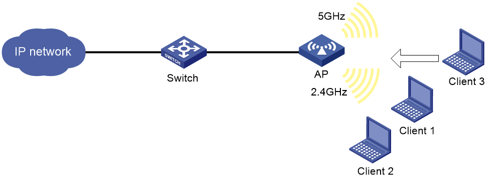
Network requirements
As shown in Figure 40, both the 5 GHz radio and the 2.4 GHz radio are enabled on the AP. Configure band navigation and load balancing for band navigation to load balance the radios.
Configuration procedure
1. Click the network view tab at the bottom of the page.
2. Configure a wireless service:
a. From the navigation tree, select Wireless Configuration > Wireless Networks.
b. Access the page for adding a wireless network to perform the following tasks:
- Set the name of the wireless service to service.
- Set its SSID to band-navigation.
- Disable fast association.
- Enable the wireless service.
3. Configure the AP:
a. From the navigation tree, select Wireless Configuration > AP Management.
b. On the WLAN Service Settings tab, bind wireless service service to both the 5 GHz and 2.4 GHz radios of the AP.
4. Configure band navigation:
a. From the navigation tree, select Wireless Configuration > Radio Management.
b. Click the Band Navigation tab.
c. Access the details page for global configuration to perform the following tasks:
- Enable band navigation globally.
- Set the session threshold to 5.
- Set the session gap threshold to 2.
Verifying the configuration
# On the Monitoring > Clients page, verify that the 5 GHz radio and the 2.4 GHz radio of the AP are load balanced.
Bonjour gateway configuration example
Network requirements
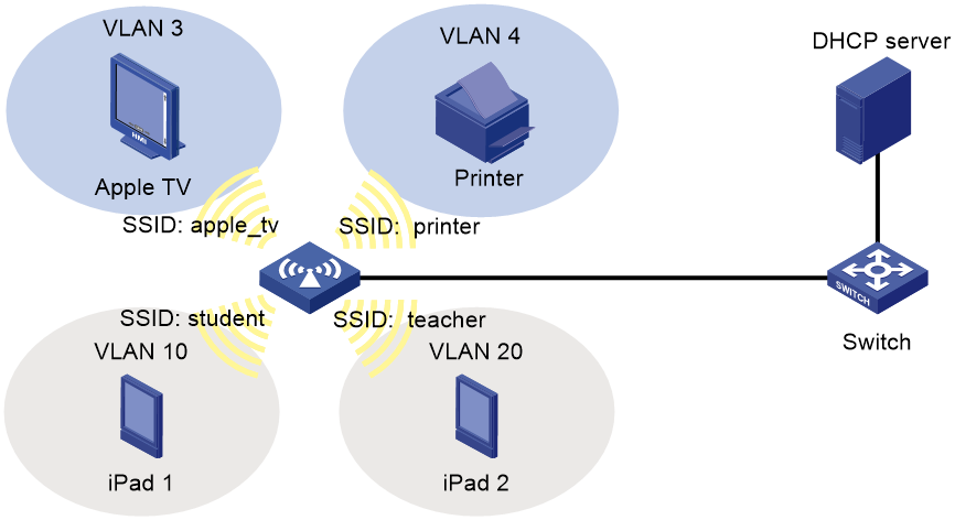
As shown in Figure 41, Apple TV, Printer, iPad 1, and iPad 2 associate with the AP through wireless services with SSIDs apple_tv, printer, student, and teacher, respectively. Apple TV, Printer, iPad 1, and iPad 2 belong to VLANs 3, 4, 10, and 20, respectively.
Configure Bonjour gateway to ensure that iPad 2 can request the services of both Apple TV and Printer and that iPad 1 can only request the service of Printer.
Configuration procedure
1. Configure the DHCP server to assign IP addresses to clients and specify the IP address of the AP as the gateway IP address. (Details not shown.)
|
|
NOTE: You must specify a DNS server address on the DHCP server because of iOS restrictions. |
2. Click the network view tab at the bottom of the page.
3. Configure wireless services:
a. From the navigation tree, select Wireless Configuration > Wireless Networks.
b. Create wireless service student, set its SSID to student, specify its default VLAN as 10, and enable the wireless service.
c. Create wireless service teacher, set its SSID to teacher, specify its default VLAN as 20, and enable the wireless service.
d. Create wireless service apple_tv, set its SSID to apple_tv, specify its default VLAN as 3, and enable the wireless service.
e. Create wireless service printer, set its SSID to printer, specify its default VLAN as 4, and enable the wireless service.
4. Configure the AP:
a. From the navigation tree, select Wireless Configuration > AP Management.
b. On the WLAN Service Settings tab, bind wireless services student, teacher, apple_tv, and printer to radios.
5. Configure the Bonjour gateway:
a. From the navigation tree, select Wireless Configuration > Applications.
b. Click the Bonjour tab.
c. Enter the global configuration page, enable Bonjour gateway, and select the custom service mode.
d. Click the Policies tab.
e. Create Bonjour policy teacher, specify VLANs 3 and 4 as its service VLANs.
f. Create Bonjour policy student, specify VLAN 4 as its service VLAN.
g. Click the Service Type tab.
h. Activate service types airplay, raop, and printer.
i. Click the WLAN Service tab.
j. Bind wireless service teacher to Bonjour policy teacher.
k. Bind wireless service student to Bonjour policy student.
Verifying the configuration
WLAN mesh configuration example
Network requirements
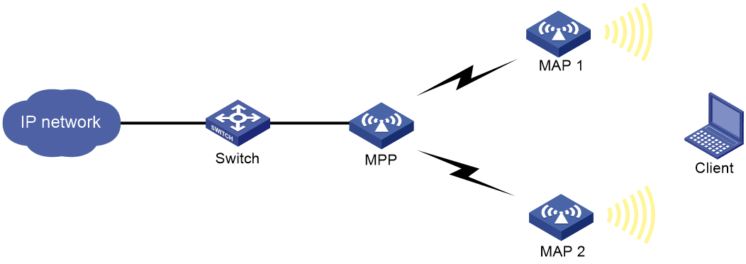
As shown in Figure 42, the MPP connects to the AC through a switch. Configure the MPP, MAP 1, and MAP 2 to use channel 149 and 5 GHz radios in 802.11n mode to establish mesh links for the client to access network resources.
Restrictions and guidelines
Configurations in this example are required on the MPP and MAPs, unless otherwise stated.
Configuration procedure
1. Click the network view tab at the bottom of the page.
2. Configure a wireless service (only on the MAPs):
a. From the navigation pane, select Wireless Configuration > Wireless Networks.
b. Create a wireless service named service.
c. Set the SSID to mesh-network.
d. Enable the wireless service.
3. Configure APs (only on the MAPs):
a. From the navigation pane, select Wireless Configuration > AP Management.
b. On the WLAN Service Settings tab, bind wireless service service to radio 1.
4. Configure a mesh profile:
a. From the navigation pane, select Wireless Configuration > Applications.
b. On the Mesh Services tab, click the Add icon + in the Mesh Profile area.
c. Set the profile number to 1.
d. Enable the mesh profile.
e. Set the mesh ID to 1.
f. Set the authentication and key management mode to SAE and specify the key as 12345678.
g. Retain the default settings for the other fields.
5. Bind the mesh profile to the 5 GHz radio:
a. From the navigation pane, select Wireless Configuration > Applications.
b. On the Mesh Services tab, click the More icon in the Binding Info area.
c. Bind mesh profile 1 to radio 1.
6. Configure the peer whitelist (only on the MAPs):
a. From the navigation pane, select Wireless Configuration > Applications.
b. On the Mesh Services tab, click the More icon in the Mesh Peer Whitelist area.
c. To avoid loops, add the MPP to the whitelist of MAP 1 and MAP 2 for the MAPs to establish mesh links only with the MPP.
7. Configure the radio mode and channel:
a. From the navigation pane, select Wireless Configuration > Radio Management.
b. Configure the 5 GHz radio as follows:
- Set the radio mode to 802.11n (5 GHz).
- Set the channel to 149.
- Enable the radio.
Verifying the configuration
Verify that the client can access the network and you can view mesh link packet statistics from the Web interface.
Multicast optimization configuration example
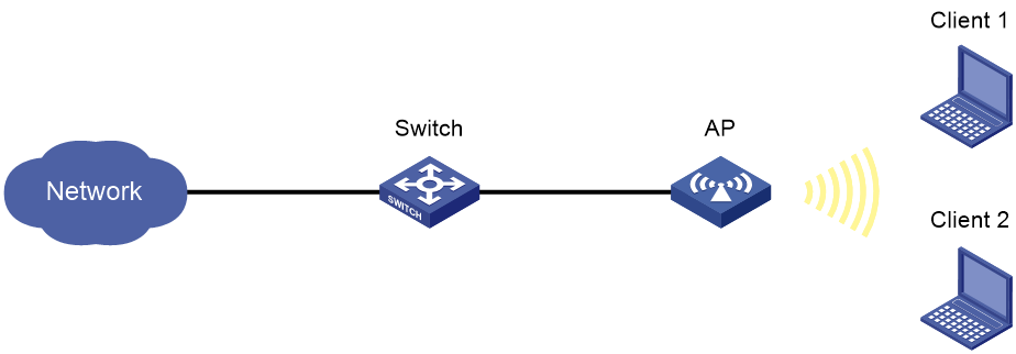
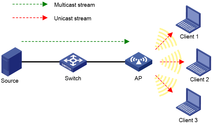
Network requirements
As shown in Figure 43, the AP provides wireless services to the clients through SSID service. Configure WLAN multicast optimization to manage multicast packet forwarding.
Configuration procedure
1. Click the network view tab at the bottom of the page.
2. Configure the wireless service:
a. From the navigation tree, select Wireless Configuration > Wireless Networks.
b. Create wireless service service1, set its SSID to service, and enable the wireless service.
3. Bind the wireless service to the 5 GHz radio of the AP:
a. From the navigation tree, select Wireless Configuration > Wireless Networks.
b. Select wireless service service1.
c. Click Bind to Radio.
d. Select the 5 GHz radio of the AP, and click Bind.
4. Configure multicast optimization:
a. From the navigation tree, select Wireless Configuration > Applications.
b. Click the Multicast Optimization tab.
c. Enter the IPv4 multicast optimization page.
d. Click the Multicast Optimization Status tab.
e. Enable multicast optimization for wireless service service1.
f. Click the Advanced Configuration tab.
g. Configure the parameters as follows:
h. Set the entry aging time to 300 seconds, entry limit to 1024, entry limit per client to 256, and client limit to 2.
i. Select the action Drop multicast packets.
j. Set the packet rate limit interval to 60 seconds and the threshold to 100.
Verifying the configuration
# Verify the following information after Client 1 and Client 2 join the multicast group with the address 230.1.1.1 and the multicast source address 1.1.1.1 has been specified:
· The AP has created multicast optimization entries for Client 1 and Client 2.
· Client 1 and Client 2 can receive traffic from the multicast source.
· After Client 3 joins the multicast group with the address 230.1.1.1 and the multicast source address 1.1.1.1 has been specified, Client 1, Client 2, and Client 3 cannot receive traffic from the multicast source because the number of clients that WLAN multicast optimization supports exceeds the limit.
RF ping configuration example
Network requirements
Use RF ping to check the quality of the wireless link between the AP and the client with MAC address 04-0A-00-00-30-00.
Figure 44 Network diagram

Configuration procedure
1. Click the network view tab at the bottom of the page.
2. From the navigation tree, select Tools > RF Ping.
3. Enter the MAC address of the client.