- Table of Contents
- Related Documents
-
| Title | Size | Download |
|---|---|---|
| 05-Network features | 417.21 KB |
Wireless service configuration
Bandwidth guaranteeing features
EDCA parameters and ACK policies
Configuring device classification
User-defined attack detection based on signatures
Configuring the alarm-ignored device list
Whitelist and blacklist features
Configuration restrictions and guidelines
Multicast optimization entry limits
Rate limits for IGMP/MLD packets from clients
Bonjour service advertisement snooping and caching
Wireless configuration
WLAN
WLAN access
WLAN access provides access to WLANs for wireless clients.
Wireless service
A wireless service defines a set of wireless service attributes, such as SSID and authentication method.
SSID
A service set identifier is the name of a WLAN.
SSID hiding
APs advertise SSIDs in beacon frames. If the number of clients in a BSS exceeds the limit or the BSS is unavailable, you can enable SSID-hidden to prevent clients from discovering the BSS. When SSID-hidden is enabled, the BSS hides its SSID in beacon frames and does not respond to broadcast probe requests. A client must send probe requests with the specified SSID to access the WLAN. This feature can protect the WLAN from being attacked.
SSID-based user isolation
When SSID-based user isolation is enabled for a service, the device isolates all wireless users that access the network through the service in the same VLAN.
Wireless service binding
If you bind a wireless service to a radio, the AP creates a BSS based on the wireless services attributes.
Link layer authentication
The original IEEE 802.11 is a Pre Robust Security Network Association (Pre-RSNA) mechanism. This mechanism is vulnerable to security attacks such as key exposure, traffic interception, and tampering. To enhance WLAN security, IEEE 802.11i (the RSNA mechanism) was introduced. You can select either of the Pre-RSNA or RSNA as needed to secure your WLAN.
IEEE 802.11i encrypts only WLAN data traffic. Unencrypted WLAN management frames are open to attacks on secrecy, authenticity, and integrity. IEEE 802.11w offers management frame protection based on the 802.11i framework to prevent attacks such as forged de-authentication and disassociation frames.
Pre-RSNA mechanism
The pre-RSNA mechanism uses the open system and shared key algorithms for authentication and uses WEP for data encryption. WEP uses the stream cipher RC4 for confidentiality and supports key sizes of 40 bits (WEP40), 104 bits (WEP104), and 128 bits (WEP128).
RSNA mechanism
The RSNA mechanism includes WPA and RSN security modes. RSNA provides the following features:
· 802.1X and PSK authentication and key management (AKM) for authenticating user integrity and dynamically generating and updating keys.
¡ 802.1X—802.1X performs user authentication and generates the pairwise master key (PMK) during authentication. The client and AP use the PMK to generate the pairwise transient key (PTK).
¡ Private PSK—The MAC address of the client is used as the PSK to generate the PMK. The client and AP use the PMK to generate the PTK.
¡ PSK—The PSK is used to generate the PMK. The client and AP use the PMK to generate the PTK.
· Temporal key integrity Protocol (TKIP) and Counter Mode CBC-MAC Protocol (CCMP) mechanisms for encrypting data.
Key types
802.11i uses the PTK and group temporary key (GTK). The PTK is used in unicast and the GTK is used in multicast and broadcast.
WPA key negotiation
WPA uses EAPOL-Key packets in the four-way handshake to negotiate the PTK, and in the two-way handshake to negotiate the GTK.
RSN key negotiation
RSN uses EAPOL-Key packets in the four-way handshake to negotiate the PTK and the GTK.
Key updates
Key updates enhance WLAN security. Key updates include PTK updates and GTK updates.
· PTK updates—Updates for the unicast keys using the four-way handshake negotiation.
· GTK updates—Updates for the multicast keys using the two-way handshake negotiation.
Authorization information ignoring
You can configure the device to ignore the authorization information received from the server (local or remote) after a client passes 802.1X or MAC authentication. Authorization information includes VLAN, ACL, and user profile.
Intrusion protection
When the authenticator detects an association request from a client that fails authentication, intrusion protection is triggered. The feature takes one of the following predefined actions on the BSS where the request is received:
· Adds the source MAC address of the request to the blocked MAC address list and drops the request packet. The client at a blocked MAC address cannot establish connections with the AP within a user-configurable block period.
· Temporarily stops the BSS where the request is received until the BSS is enabled manually on the radio interface.
· Stops the BSS where the request is received for a user-configurable stop period.
Cipher suites
· TKIP—TKIP and WEP both use the RC4 algorithm. You can change the cipher suite from WEP to TKIP by updating the software without changing the hardware. TKIP has the following advantages over WEP:
¡ TKIP provides longer initialization vectors (IVs) to enhance encryption security. Compared with WEP encryption, TKIP encryption uses the 128-bit RC4 encryption algorithm, and increases the length of IVs from 24 bits to 48 bits.
¡ TKIP allows for dynamic key negotiation to avoid static key configuration. TKIP dynamic keys cannot be easily deciphered.
¡ TKIP offers MIC and countermeasures. If a packet has been tampered with, it will fail the MIC. If two packets fail the MIC in a period, the AP automatically takes countermeasures by stopping providing services in a period to prevent attacks.
· CCMP—CCMP is based on the Counter-Mode/CBC-MAC (CCM) of the Advanced Encryption Standard (AES) encryption algorithm.
CCMP contains a dynamic key negotiation and management method. Each client can dynamically negotiate a key suite, which can be updated periodically to further enhance the security of the CCMP cipher suite. During the encryption process, CCMP uses a 48-bit packet number (PN) to make sure each encrypted packet uses a different PN. This improves WLAN security.
Authentication mode
PSK authentication
PSK authentication requires the same PSK to be configured for both an AP and a client. PSK integrity is verified during the four-way handshake. If PTK negotiation succeeds, the client passes the authentication.
802.1X authentication
The authenticator uses EAP relay or EAP termination to communicate with the RADIUS server.
· Online user handshake—The online user handshake feature examines the connectivity status of online 802.1X clients. The device periodically sends handshake messages to online clients. If the device does not receive any responses from an online client after it has made the maximum handshake attempts, the device sets the client to offline state.
· Online user handshake security—The online user handshake security feature adds authentication information in the handshake messages. This feature can prevent illegal clients from forging legal 802.1X clients to exchange handshake messages with the device. With this feature, the device compares the authentication information in the handshake response message from a client with that assigned by the authentication server. If no match is found, the device logs off the client.
· Periodic online user reauthentication—Periodic online user reauthentication tracks the connection status of online clients, and updates the authorization attributes assigned by the server. The attributes include the ACL, VLAN, and user profile-based QoS.
Dynamic WEP mechanism
IEEE 802.11 provides the dynamic WEP mechanism to ensure that each user uses a private WEP key. For unicast communications, the mechanism uses the WEP key negotiated by the client and server during 802.1X authentication. For multicast and broadcast communications, the mechanism uses the configured WEP key. If you do not configure a WEP key, the AP randomly generates a WEP key for broadcast and multicast communications.
After the client passes 802.1X authentication, the AP sends the client an RC4-EAPOL packet that contains the unicast WEP key ID, and the multicast and broadcast WEP key and key ID. The unicast WEP key ID is 4.
ACL-based access control
This feature controls client access by using ACL rules.
Upon receiving an association request from a client, the device performs the following actions:
· Allows the client to access the WLAN if a match is found and the rule action is permit.
· Denies the client's access to the WLAN if no match is found or the matched rule has a deny statement.
AP management
Wireless service configuration
If you bind a wireless service to a radio interface on the fat AP, the AP creates a BSS based on the wireless services attributes. Clients in the same BSS can communicate with each other.
Region code
A region code determines characteristics such as available frequencies, available channels, and transmit power level. Set a valid region code before configuring an AP.
To prevent regulation violation caused by region code modification, lock the region code.
LED lighting mode
You can configure LEDs on an AP to flash in the following modes:
· quiet—All LEDs are off.
· awake—All LEDs flash once every minute.
· always-on—All LEDs are steady on.
· normal—This mode can identify the running status of an AP.
Client rate limiting features
Client rate limiting prevents aggressive use of bandwidth by one client and ensures fair use of bandwidth among clients associated with the same AP.
Client rate limit mode
The following modes are available for client rate limiting:
· Dynamic mode—Sets the total bandwidth shared by all clients. The rate limit for each client is the total rate divided by the number of online clients. For example, if the total rate is 10 Mbps and five clients are online, the rate limit for each client is 2 Mbps.
· Static mode—Sets the bandwidth that can be used by each client. When the rate limit multiplied by the number of associated clients exceeds the available bandwidth provided by the AP, the clients might not get the set bandwidth.
You can configure the client rate limit mode only for service-based client rate limiting.
Client rate limit methods
You can use the following methods to limit the traffic rate:
· Client-type-based client rate limiting—The setting takes effect on all clients. Traffic rate of each client type cannot exceed the corresponding setting.
· Service-based client rate limiting—The setting takes effect on all clients associated with the same wireless service.
If more than one method and mode are configured, all settings take effect. The rate for a client will be limited to the minimum value among all the client rate limiting settings.
Bandwidth guaranteeing features
Bandwidth guaranteeing provides the following functions:
· Ensures that traffic from all BSSs can pass through freely when the network is not congested.
· Ensures that each BSS can get the guaranteed bandwidth when the network is congested.
This feature improves bandwidth efficiency and maintains fair use of bandwidth among WLAN services. For example, you assign SSID1, SSID2, and SSID3 25%, 25%, and 50% of the total bandwidth. When the network is not congested, SSID1 can use all idle bandwidth in addition to its guaranteed bandwidth. When the network is congested, SSID1 is guaranteed with 25% of the bandwidth.
This feature applies only to AP-to-client traffic.
WMM features
An 802.11 network provides contention-based wireless access. To provide applications with QoS services, IEEE developed 802.11e for 802.11-based WLANs.
While IEEE 802.11e was being standardized, Wi-Fi Alliance defined the Wi-Fi Multimedia (WMM) standard to allow QoS provision devices of different vendors to interoperate. WMM enables a WLAN to provide QoS services, so that audio and video applications can have better performance in WLANs.
To view detailed WMM information, access the All Networks > Wireless Configuration > Wireless QoS > Wi-Fi Multimedia page, and then click the More icon on any list of the page.
WMM state
To configure the WMM state and SVP mappings, access the WMM configuration tab on the detailed WMM information page.
SVP mapping assigns packets that have the protocol ID 119 in the IP header to the AC-VI or AC-VO queue to provide SVP packets with the specified priority. When SVP mapping is disabled, SVP packets are assigned to the AC-BE queue.
EDCA parameters and ACK policies
On the EDCA Radio tab of the detailed WMM information page, you can view and modify the EDCA parameters and ACK policies.
EDCA is a channel contention mechanism defined by WMM to preferentially transmit packets with high priority and allocate more bandwidth to such packets.
WMM defines the following EDCA parameters:
· Arbitration inter-frame spacing number—In 802.11-based WLAN, each client has the same idle duration (DIFS), but WMM defines an idle duration for each AC. The idle duration increases as the AIFSN increases.
· Exponent form of CWmin/Exponent form of CWmax—ECWmin/ECWmax determines the backoff slots, which increase as the two values increase.
· Transmission opportunity limit—TXOP limit specifies the maximum time that a client can hold the channel after a successful contention. A larger value represents a longer time. If the value is 0, a client can send only one packet each time it holds the channel.
WMM defines the following ACK policies:
· Normal ACK—The recipient acknowledges each received unicast packet.
· No ACK—The recipient does not acknowledge received packets during wireless packet exchange. This policy improves the transmission efficiency in an environment where communication quality is strong and interference is weak. If communication quality deteriorates, this policy might increase the packet loss rate.
EDCA parameters
On the EDCA Parameters for Clients tab of the detailed WMM information page, you can view and modify EDCA parameters, and enable or disable a CAC policy.
Connect Admission Control (CAC) limits the number of clients that can use high-priority ACs (AC-VO and AC-VI) to make sure there is enough bandwidth for these clients. If a high-priority AC (AC-VO or AC-VI) is required, a client must send a request to the AP. The AP returns a positive or negative response based on the channel-usage-based admission policy or client-based admission policy. If the request is rejected, the AP assigns AC-BE to clients.
Client WMM statistics
On the Station WMM Information tab of the detailed WMM information page, you can view the following information:
· The device's basic information such as SSID.
· Data traffic statistics.
· APSD attribute for an AC queue.
U-APSD is a power saving method defined by WMM to save client power. U-APSD enables clients in sleep mode to wake up and receive the specified number of packets only after receiving a trigger packet. U-APSD improves the 802.11 APSD power saving mechanism.
U-APSD is automatically enabled after you enable WMM.
Traffic statistics
On the Station Traffic Stream tab of the detailed WMM information page, you can view the following information:
· User priority for packets from wired networks.
· Traffic Identifier.
· Traffic direction.
· Surplus bandwidth allowance.
WIPS
Wireless Intrusion Prevention System (WIPS) helps you monitor your WLAN, detect attacks and rogue devices, and take countermeasures. WIPS provides a complete solution for WLAN security.
WIPS contains the network management module and sensors (APs enabled with WIPS). They provide the following functions:
· The sensors monitor the WLAN, collect channel information, determines attacks and rogue devices, takes countermeasures, and triggers alarms.
· The network management module allows you to configure WIPS in the Web interface. It provides configuration management, report generation, and alarm management functions.
WIPS provides the following features:
· Attack detection—WIPS detects attacks by listening for 802.11 frames and triggers alarms to notify the administrator.
· Signature-based attack detection—WIPS provides signature-based attack detection. A signature contains a packet identification method and actions to take on the matching packets.
· Device classification—WIPS identifies wireless devices by listening for 802.11 frames and classifies the devices based on the classification rules.
· Countermeasures—WIPS enables you to take countermeasures against rogue devices.
Enabling WIPS
Before enabling WIPS for a radio of an AP, you must add the AP to a virtual security domain (VSD).
Configuring a VSD
You can apply a classification policy, attack detection policy, signature policy, or countermeasure policy to a VSD to enable the policy to take effect on the radios in the VSD.
Configuring device classification
Classification policy
You can enable WIPS to classify devices by using either of the following methods:
· Automatic classification—WIPS automatically classifies devices by adding the MAC addresses, OUIs, or SSIDs of the devices to the specified lists. WIPS also allows you to classify APs by using user-defined AP classification rules.
· Manual classification—You manually specify a category for a device. Manual classification is applicable only to APs.
If you configure both automatic classification and manual classification, manual classification takes effect.
AP classification
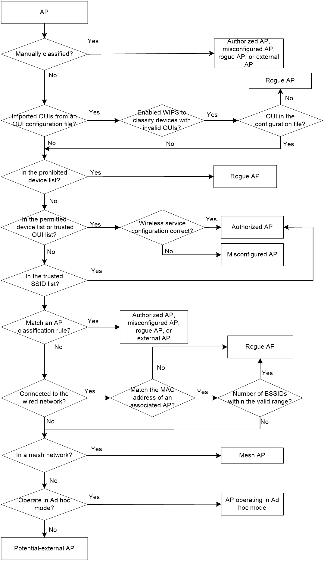
As shown in Table 1, WIPS classifies detected APs according to the predefined classification rules.
|
Category |
Description |
Classification rule |
|
Authorized AP |
An AP that is permitted in the WLAN. |
· Not in the prohibited device list. · Configured as an authorized AP. |
|
Rogue AP |
An AP that cannot be used in the WLAN. |
· In the prohibited device list. · Not in the OUI configuration file. · Configured as a rogue AP. |
|
Misconfigured AP |
An AP that can be used in the WLAN but has incorrect configuration. |
· In the permitted device list but with an incorrect SSID. · Not in the prohibited device list but in the OUI configuration file. · In the trusted OUI list or permitted device list but not connected to the AC. |
|
External AP |
An AP that is in an adjacent WLAN. |
· Configured as an external AP. · Classified as an external AP by a signature. |
|
Ad hoc |
An AP operating in Ad hoc mode. WIPS detects Ad hoc APs by listening to beacon frames. |
N/A |
|
Potential-authorized AP |
An AP that is possibly authorized. |
Not in any of the following lists: · Permitted device list. · Prohibited device list. · Trusted OUI list. |
|
Potential-rogue AP |
An AP that is possibly a rogue AP. |
Has incorrect wireless configuration and is not in any of the following lists: · Permitted device list. · Prohibited device list. · Trusted OUI list. If the wired port on an AP has been connected to the network, the AP is a rogue AP. |
|
Potential-external AP |
An AP that is possibly an external AP. |
· Has incorrect wireless service configuration. · The wired port has not been connected to the network. · Not in any of the following lists: ¡ Permitted device list. ¡ Prohibited device list. ¡ Trusted OUI list. |
|
Uncategorized AP |
An AP whose category cannot be determined. |
N/A |
WIPS classifies detected APs by following the procedure shown in Figure 1.
Figure 1 AP classification flow
Client classification
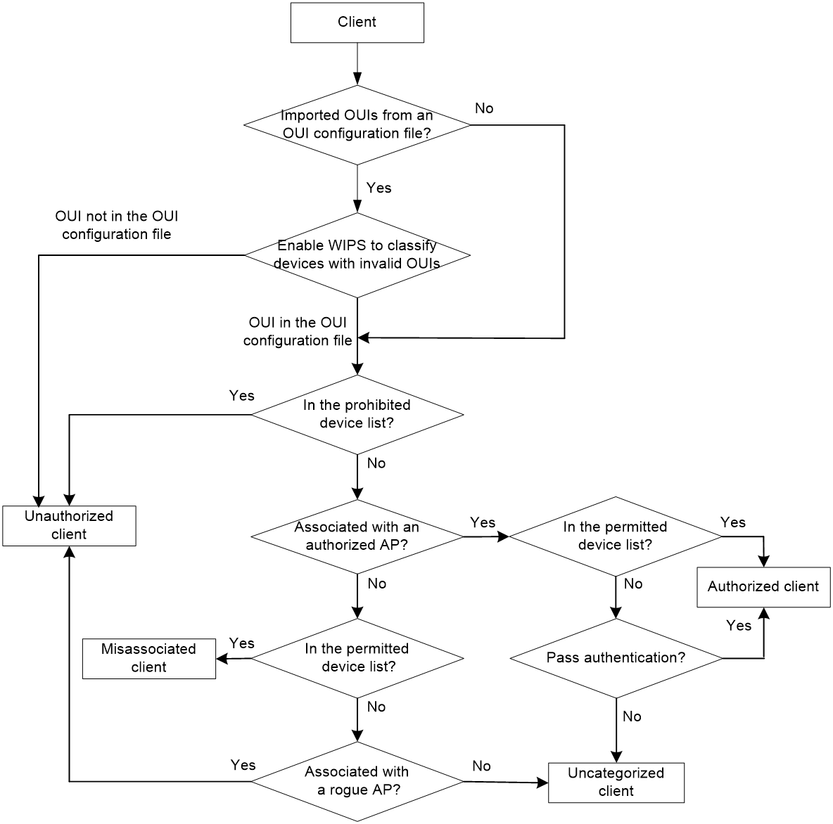
As shown in Table 2, WIPS classifies detected clients according to the predefined classification rules.
|
Category |
Description |
Classification rule |
|
Authorized client |
A client that is permitted in the WLAN. |
· In the permitted device list and associated with an authorized AP. · Has passed authentication and is associated with an authorized AP. |
|
Unauthorized client |
A client that cannot be used in the WLAN. |
· In the prohibited device list. · Associated with a rogue AP. · Not in the OUI configuration file. |
|
Misassociated client |
A client that is associated with an unauthorized AP. |
In the permitted device list but associated with an unauthorized AP. A misassociated client might bring security threats to the network. |
|
Uncategorized client |
A client whose category cannot be determined. |
N/A |
WIPS classifies detected clients by following the procedure shown in Figure 2.
Figure 2 Client classification flow
Configuring attack detection
WIPS detects attacks by listening to 802.11 frames and triggers alarms to notify the administrator.
Device entry attack detection
Attackers can send invalid packets to WIPS to increase processing costs. WIPS periodically examines the learned device entries to determine whether to rate limit device entry learning. If the number of AP or client entries learned within the specified interval exceeds the threshold, WIPS triggers an alarm and stops learning new entries.
Flood attack detection
An AP might be facing a flood attack if it receives a large number of same-type frames within a short period of time. To prevent the AP from being overwhelmed, WIPS periodically examines incoming packet statistics, and alarms when it detects a suspicious flood attack. WIPS can detect the following flood attacks:
· Probe request/association request/reassociation request flood attack—Floods the association table of an AP by imitating many clients sending probe requests/association requests/reassociation requests to the AP.
· Authentication request flood attack—Floods the association table of an AP by imitating many clients sending authentication requests to the AP.
· Beacon flood attack—Floods beacon frames imitating a large number of fake APs to interrupt client association.
· Block Ack flood attack—Floods Block Ack frames to the AP to interrupt the operation of the Block Ack mechanism.
· RTS/CTS flood attack—Floods RTS/CTS frames to reserve the RF medium and force other wireless devices sharing the RF medium to hold back their transmissions. This attack takes advantage of vulnerabilities of the virtual carrier mechanism.
· Broadcast/unicast deauthentication flood attack—Spoofs deauthentication frames from the AP to the associated clients to disassociate the clients from the AP. This attack can rapidly terminate wireless services to multiple clients.
· Broadcast/unicast disassociation flood attack—Spoofs disassociation frames from the AP to the associated clients to disassociate the clients from the AP. This attack can rapidly terminate wireless services to multiple clients.
· EAPOL-start flood attack—Exhausts the AP's resources by imitating many clients sending EAPOL-start frames defined in IEEE 802.1X to the AP.
· Null data flood attack—Spoofs null data frames from a client to the AP. The AP determines that the client is in power save mode and buffers frames for the client. When the aging time of the buffered frames expires, the AP discards the frames. This interrupts the client's communication with the AP.
· EAPOL-logoff flood attack—The IEEE 802.1X standard defines the authentication protocol using Extensible Authentication Protocol over LANs (EAPOL). A client needs to send an EAPOL-logoff frame to terminate the session with an AP. The EAPOL-logoff frames are not authenticated, and an attacker can spoof EAPOL-logoff frames to disassociate a client.
· EAPOL-success/failure flood attack—In a WLAN using 802.1X authentication, an AP sends an EAP-success or EAP-failure frame to a client to inform authentication success or failure. An attacker can spoof the MAC address of an AP to send EAP-success or EAP-failure frames to a client to disrupt the authentication process.
Malformed packet detection
WIPS determines that a frame is malformed if the frame matches the criteria shown in Table 3, and then it triggers alarms and logs. WIPS can detect 16 kinds of malformed packets.
Table 3 Malformed frame match criteria
|
Detection type |
Applicable frames |
Match criteria |
|
Duplicate IE detection |
All management frames |
Duplicate IE. This type of detection is not applicable to vendor-defined IEs. |
|
FATA-Jack detection |
Authentication frames |
The value of the authentication algorithm number is 2. |
|
Abnormal IBSS and ESS setting detection |
· Beacon frames · Probe response frames |
Both IBSS and ESS are set to 1. |
|
Invalid source address detection |
All management frames |
· The TO DS is 1, indicating that the frame is sent to the AP by a client. · The source MAC address of the frame is a multicast or broadcast address. |
|
Malformed association request frame detection |
Association request frames |
The frame length is 0. |
|
Malformed authentication request frame detection |
Authentication request frames |
· The authentication algorithm number does not conform to the 802.11 protocol and is larger than 3. · The authentication transaction sequence number is 1 and the status code is not 0. · The authentication transaction sequence number is larger than 4. |
|
Invalid deauthentication code detection |
Deauthentication frames |
The reason code is 0 or is in the range of 67 to 65535. |
|
Invalid disassociation code detection |
Disassociation frames |
The reason code is 0 or is in the range of 67 to 65535. |
|
Malformed HT IE detection |
· Beacon frames · Probe responses · Association responses · Reassociation requests |
· The SM power save value for the HT capabilities IE is 2. · The secondary channel offset value for the HT operation IE is 2. |
|
Invalid IE length detection |
All management frames |
The IE length does not conform to the 802.11 protocol. |
|
Invalid packet length detection |
All management frames |
The remaining length of the IE is not zero after the packet payload is resolved. |
|
Malformed probe response frame detection |
Probe response frames |
The frame is not a mesh frame and its SSID length is 0. |
|
Oversized EAPOL key detection |
EAPOL-Key frames |
The TO DS is 1 and the length of the key is larger than 0. |
|
Oversized SSID detection |
· Beacon frames · Probe requests · Probe responses · Association request frames |
The SSID length is larger than 32. |
|
Redundant IE detection |
All management frames |
The IE is not a necessary IE to the frame and is not a reserved IE. |
|
Oversized duration detection |
· Unicast management frames · Unicast data frames · RTS, CTS, and ACK frames |
The packet duration value is larger than the specified threshold. |
Attack detection
· Spoofing attack detection
In a spoofing attack, the attacker sends frames on behalf of another device to threaten the network. WIPS supports detection of the following spoofing attacks:
¡ Frame spoofing—A fake AP spoofs an authorized AP to send beacon or probe response frames to induce clients to associate with it.
¡ AP MAC address spoofing—A client spoofs an authorized AP to send deauthentication or disassociation frames to other clients. This can cause the clients to go offline and affect the correct operation of the WLAN.
¡ Client MAC address spoofing—A fake AP spoofs an authorized client to associate with an authorized AP.
When the RC4 encryption algorithm, used by the WEP security protocol, uses an insecure IV, the WEP key is more likely to be cracked. Such an insecure IV is called a weak IV. WIPS prevents this kind of attack by detecting the IV in each WEP packet.
· Windows bridge detection
When a wireless client connected to a wired network establishes a Windows bridge through the wired NIC, the client can bridge an external AP with the internal network. This might bring security problems to the internal network. WIPS detects Windows bridges by analyzing data frames sent by associated clients.
· Detection on clients with the 40 MHz bandwidth mode disabled
802.11n devices support both the 20 MHz and 40 MHz bandwidth modes. If the 40 MHz bandwidth mode is disabled on a client, other clients associated with the same AP as the client must also use the 20 MHz bandwidth. This affects network throughput and efficiency.
WIPS detects such clients by detecting probe request frames sent by the clients.
Omerta is a DoS attack tool based on the 802.11 protocol. It sends disassociation frames with the reason code 0x01 to disassociate clients. Reason code 0x01 indicates an unknown disassociation reason. WIPS detects Omerta attacks by detecting the reason code of each disassociation frame.
· Unencrypted device detection
An authorized AP or client that is transmitting unencrypted frames might bring security problems to the network. WIPS detects unencrypted devices by analyzing the frames sent the by authorized APs or clients.
An attacker sets up a rogue AP with the same SSID as a hotspot to lure the clients to associate with it. After the clients associate with the malicious AP, the attacker initiates further attacks to obtain client information.
You can configure a hotspot file to enable WIPS to detect hotspot attacks.
An AP operating in HT-greenfield mode might cause collisions, errors, and retransmissions because it cannot communicate with 802.11a/b/g devices. WIPS detects HT-greenfield APs by analyzing the beacon frames or probe response frames sent by APs.
· Association/reassociation DoS attack detection
An association/reassociation DoS attack floods the association table of an AP by imitating many clients sending association requests to the AP. When the number of entries in the table reaches the upper limit, the AP cannot process requests from legitimate clients.
In an MITM attack, the attacker sets up a rogue AP and lures a client to associate with it. Then the rogue AP spoofs the MAC address of the client to associate with the authorized AP. When the client and the authorized AP communicate, the rogue AP captures packets from both the client and the authorized AP. The rogue AP might modify the frames and obtain the frame information. WIPS detects MITM attacks by detecting clients that are disassociated from an authorized AP and associated with a honeypot AP.
An attacker might intrude on the internal networks through a wireless bridge. When detecting a wireless bridge, WIPS generates an alarm. If the wireless bridge is in a mesh network, WIPS records the mesh link.
· AP channel change detection
WIPS detects the channel change events for APs in the WLAN.
· Broadcast disassociation/deauthentication attack detection
An attacker spoofs a legitimate AP to send a broadcast disassociation or deauthentication frame to log off all clients associated with the AP.
· AP impersonation attack detection
In an AP impersonation attack, a malicious AP that has the same BSSID and ESSID as a legitimate AP lures the clients to associate with it. Then this impersonating AP initiates hotspot attacks or fools the detection system.
WIPS detects AP impersonation attacks by detecting the interval at which an AP sends beacon frames.
WIPS detects the number of APs in the WLAN and triggers an alarm for an AP flood attack when the number of APs exceeds the specified threshold.
In a honeypot AP attack, the attacker sets up a malicious AP to lure clients to associate with it. The SSID of the malicious AP is similar to the SSID of a legitimate AP. After a client associates with a honeypot AP, the honeypot AP initiates further attacks such as port scanning or fake authentication to obtain client information.
WIPS detects honeypot APs by detecting SSIDs of external APs. If the similarity between the SSID of an external AP and the SSID of a legitimate AP reaches the specified threshold, WIPS generates an alarm.
An attacker spoofs the MAC address of a client to send power save on frames to an AP. The AP caches the frames for the client. The attacked client cannot receive data frames because the AP determines that the client is still in power save mode. When the aging time of the cached frames expires, the AP discards the frames. WIPS detects power save attacks by determining the ratio of power save on frames to power save off frames.
A soft AP refers to a client that acts as an AP and provides wireless services. An attacker can access the internal network through a soft AP and then initiate further attacks. WIPS detects soft APs by detecting the interval at which a device switches its roles between client and AP.
· Prohibited channel detection
After you configure a permitted channel list and enable prohibited channel detection, WIPS determines that channels that are not in the permitted channel list are prohibited channels.
User-defined attack detection based on signatures
WIPS provides user-defined attack detection based on signatures. A signature contains a packet identification method and actions to take on the matching packets. The sensor matches the detected packets against the signature, and takes actions defined in the signature if a packet matches the signature.
A signature can contain a maximum of six subsignatures, which can be defined based on the frame type, MAC address, serial ID, SSID length, SSID, and frame pattern. A packet matches a signature only when it matches all the subsignatures in the signature.
Countermeasures
Rogue devices are susceptible to attacks and might bring security problems to the WLAN. WIPS enables you to take countermeasures against rogue devices.
Configuring the alarm-ignored device list
For wireless devices in an alarm-ignored device list, WIPS only monitors them but does not trigger any alarms.
Whitelist and blacklist features
· Whitelist—Contains the MAC addresses of all clients allowed to access the WLAN. Frames from clients not in the whitelist are discarded. This list is manually configured.
· Static blacklist—Contains the MAC addresses of clients forbidden to access the WLAN. This list is manually configured.
· Dynamic blacklist—Contains the MAC addresses of clients forbidden to access the WLAN through specific APs within the specified aging time. A client is dynamically added to the list if an AP determines this client is a rogue client.
When the AP receives an association request, the AP performs the following operations to determine whether to permit the client:
1. Searches the whitelist.
¡ If the client MAC address does not match any entries in the whitelist, the client is rejected.
¡ If there is a match, the client is permitted.
2. Searches the static and dynamic blacklists if no whitelist entries exist.
¡ If the client MAC address matches an entry in either blacklist, the client is rejected.
¡ If there is no match, or no blacklist entries exist, the client is permitted.
Radio management
Radio frequency (RF) is a rate of electrical oscillation in the range of 300 kHz to 300 GHz. WLAN uses the 2.4 GHz band and 5 GHz band radio frequencies as the transmission media. The 2.4 GHz band includes radio frequencies from 2.4 GHz to 2.4835GHz. The 5 GHz band includes radio frequencies from 5.150 GHz to 5.350 GHz and from 5.725 GHz to 5.850 GHz.
The term "radio frequency" or its abbreviation RF is also used as a synonym for "radio" in wireless communication.
Radio mode
|
|
IMPORTANT: Changing the mode of an enabled radio logs off all associated clients. |
IEEE defines the 802.11a, 802.11b, 802.11g, 802.11n, 802.11ac, and 802.11ax radio modes. Table 4 provides a comparison of these radio modes.
|
|
NOTE: · H3C defines an 802.11gac radio mode and an 802.11gax radio mode that enable 802.11ac and 802.11ax radios to use the 2.4 GHz band. · In this document, the term "802.11ac" refers to both 802.11ac and 802.11gac and the term "802.11ax" refers to both 802.11ax and 802.11gax, unless otherwise specified. |
Table 4 Comparison of 802.11 standards
|
IEEE standard |
Frequency band |
Maximum rate |
Indoor coverage |
Outdoor coverage |
|
802.11a |
5 GHz |
54 Mbps |
About 50 m (164.04 ft) |
About 100 m (328.08 ft) |
|
802.11b |
2.4 GHz |
11 Mbps |
About 300 m (984.3 ft) |
About 600 m (1968.50 ft) |
|
802.11g |
2.4 GHz |
54 Mbps |
About 300 m (984.3 ft) |
About 600 m (1968.50 ft) |
|
802.11n |
2.4 GHz or 5 GHz |
600 Mbps |
About 300 m (984.3 ft) |
About 600 m (1968.50 ft) |
|
802.11ac |
5 GHz |
6900 Mbps |
About 30 m (98.43 ft) |
About 60 m (196.85 ft) |
|
802.11gac |
2.4 GHz |
1600 Mbps |
About 100 m (328.08 ft) |
About 200 m (656.16 ft) |
|
802.11ax |
5 GHz |
9600 Mbps |
802.11ax |
5GHz |
|
802.11gax |
2.4 GHz |
6900 Mbps |
802.11gax |
2.4GHz |
Different radio modes support different channels and transmit powers. When you edit the radio mode, the AP automatically selects a channel or transmit power if the new radio mode does not support the original channel or transmit power.
Available radio functions vary by radio mode:
· For 802.11a, 802.11b, and 802.11g radios, you can configure basic radio functions. For more information about basic radio functions, see "Basic radio functions."
· For 802.11n radios, you can configure basic radio functions and 802.11n functions. For more information about 802.11n functions, see "802.11n functions."
· For 802.11ac radios, you can configure basic radio functions, 802.11n functions, and 802.11ac functions. For more information about 802.11ac functions, see "802.11ac functions."
· For 802.11ax radios, you can configure basic radio functions, 802.11n functions, 802.11ac functions, and 802.11ax functions. For more information about 802.11ax functions, see "802.11ax functions."
Channel
A channel is a range of frequencies with a specific bandwidth.
The 2.4 GHz band has 14 channels. The bandwidth for each channel is 20 MHz and each two channels are spaced 5 MHz apart. Among the 14 channels, four groups of non-overlapping channels exist and the most commonly used one contains channels 1, 6, and 11.
The 5 GHz band can provide higher rates and is more immune to interference. There are 24 non-overlapping channels designated to the 5 GHz band. The channels are spaced 20 MHz apart with a bandwidth of 20 MHz.
Transmit power
Transmit power reflects the signal strength of a wireless device. A higher transmit power enables a radio to cover a larger area but it brings more interference to adjacent devices. The signal strength decreases as the transmission distance increases.
Transmission rate
Transmission rate refers to the speed at which wireless devices transmit traffic. It varies by radio mode and spreading, coding, and modulation schemes. The following are rates supported by different types of radios:
· 802.11a—6 Mbps, 9 Mbps, 12 Mbps, 18 Mbps, 24 Mbps, 36 Mbps, 48 Mbps, and 54 Mbps.
· 802.11b—1 Mbps, 2 Mbps, 5.5 Mbps, and 11 Mbps.
· 802.11g—1 Mbps, 2 Mbps, 5.5 Mbps, 6 Mbps, 9 Mbps, 11 Mbps, 12 Mbps, 18 Mbps, 24 Mbps, 36 Mbps, 48 Mbps, and 54 Mbps.
· 802.11n—Rates for 802.11n radios vary by channel bandwidth. For more information, see "MCS."
· 802.11ac—Rates for 802.11ac radios vary by channel bandwidth and number of spatial streams (NSS). For more information, see "VHT-MCS."
· 802.11ax—Rates for 802.11ax radios vary by channel bandwidth and number of spatial streams (NSS). For more information, see "HE-MCS."
MCS
Modulation and Coding Scheme (MCS) defined in IEEE 802.11n-2009 determines the modulation, coding, and number of spatial streams. An MCS is identified by an MCS index, which is represented by an integer in the range of 0 to 76. An MCS index is the mapping from MCS to a data rate.
Table 5 and Table 6 show sample MCS parameters for 20 MHz and 40 MHz.
When the bandwidth mode is 20 MHz, MCS indexes 0 through 15 are mandatory for APs, and MCS indexes 0 through 7 are mandatory for clients.
Table 5 MCS parameters for 20 MHz
|
MCS index |
Number of spatial streams |
Modulation |
Data rate (Mbps) |
|
|
800ns GI |
400ns GI |
|||
|
0 |
1 |
BPSK |
6.5 |
7.2 |
|
1 |
1 |
QPSK |
13.0 |
14.4 |
|
2 |
1 |
QPSK |
19.5 |
21.7 |
|
3 |
1 |
16-QAM |
26.0 |
28.9 |
|
4 |
1 |
16-QAM |
39.0 |
43.3 |
|
5 |
1 |
64-QAM |
52.0 |
57.8 |
|
6 |
1 |
64-QAM |
58.5 |
65.0 |
|
7 |
1 |
64-QAM |
65.0 |
72.2 |
|
8 |
2 |
BPSK |
13.0 |
14.4 |
|
9 |
2 |
QPSK |
26.0 |
28.9 |
|
10 |
2 |
QPSK |
39.0 |
43.3 |
|
11 |
2 |
16-QAM |
52.0 |
57.8 |
|
12 |
2 |
16-QAM |
78.0 |
86.7 |
|
13 |
2 |
64-QAM |
104.0 |
115.6 |
|
14 |
2 |
64-QAM |
117.0 |
130.0 |
|
15 |
2 |
64-QAM |
130.0 |
144.4 |
Table 6 MCS parameters for 40 MHz
|
MCS index |
Number of spatial streams |
Modulation |
Data rate (Mbps) |
|
|
800ns GI |
400ns GI |
|||
|
0 |
1 |
BPSK |
13.5 |
15.0 |
|
1 |
1 |
QPSK |
27.0 |
30.0 |
|
2 |
1 |
QPSK |
40.5 |
45.0 |
|
3 |
1 |
16-QAM |
54.0 |
60.0 |
|
4 |
1 |
16-QAM |
81.0 |
90.0 |
|
5 |
1 |
64-QAM |
108.0 |
120.0 |
|
6 |
1 |
64-QAM |
121.5 |
135.0 |
|
7 |
1 |
64-QAM |
135.0 |
150.0 |
|
8 |
2 |
BPSK |
27.0 |
30.0 |
|
9 |
2 |
QPSK |
54.0 |
60.0 |
|
10 |
2 |
QPSK |
81.0 |
90.0 |
|
11 |
2 |
16-QAM |
108.0 |
120.0 |
|
12 |
2 |
16-QAM |
162.0 |
180.0 |
|
13 |
2 |
64-QAM |
216.0 |
240.0 |
|
14 |
2 |
64-QAM |
243.0 |
270.0 |
|
15 |
2 |
64-QAM |
270.0 |
300.0 |
MCS indexes are classified into the following types:
· Mandatory MCS indexes—Mandatory MCS indexes for an AP. To associate with an 802.11n AP, a client must support the mandatory MCS indexes for the AP.
· Supported MCS indexes—MCS indexes supported by an AP except for the mandatory MCS indexes. If a client supports both mandatory and supported MCS indexes, the client can use a supported rate to communicate with the AP.
· Multicast MCS index—MCS index for the rate at which an AP transmits multicast frames.
|
|
NOTE: For all the MCS data rate tables, see IEEE 802.11n-2009. |
VHT-MCS
802.11 ac uses Very High Throughput Modulation and Coding Scheme (VHT-MCS) indexes to indicate wireless data rates. A VHT-MCS is identified by a VHT-MCS index, which is represented by an integer in the range of 0 to 9. A VHT-MCS index is the mapping from VHT-MCS to a data rate.
802.11ac supports the 20 MHz, 40 MHz, 80 MHz, and 160 MHz bandwidth modes, and supports a maximum of eight spatial streams.
Table 7 through Table 18 show VHT-MCS parameters that are supported by an AP.
Table 7 VHT-MCS parameters (20 MHz, NSS=1)
|
VHT-MCS index |
Modulation |
Data rate (Mbps) |
|
|
800ns GI |
400ns GI |
||
|
0 |
BPSK |
6.5 |
7.2 |
|
1 |
QPSK |
13.0 |
14.4 |
|
2 |
QPSK |
19.5 |
21.7 |
|
3 |
16-QAM |
26.0 |
28.9 |
|
4 |
16-QAM |
39.0 |
43.3 |
|
5 |
64-QAM |
52.0 |
57.8 |
|
6 |
64-QAM |
58.5 |
65.0 |
|
7 |
64-QAM |
65.0 |
72.2 |
|
8 |
256-QAM |
78.0 |
86.7 |
|
9 |
Not valid |
||
Table 8 VHT-MCS parameters (20 MHz, NSS=2)
|
VHT-MCS index |
Modulation |
Data rate (Mbps) |
|
|
800ns GI |
400ns GI |
||
|
0 |
BPSK |
13.0 |
14.4 |
|
1 |
QPSK |
26.0 |
28.9 |
|
2 |
QPSK |
39.0 |
43.3 |
|
3 |
16-QAM |
52.0 |
57.8 |
|
4 |
16-QAM |
78.0 |
86.7 |
|
5 |
64-QAM |
104.0 |
115.6 |
|
6 |
64-QAM |
117.0 |
130.0 |
|
7 |
64-QAM |
130.0 |
144.4 |
|
8 |
256-QAM |
156.0 |
173.3 |
|
9 |
Not valid |
||
Table 9 VHT-MCS parameters (20 MHz, NSS=3)
|
VHT-MCS index |
Modulation |
Data rate (Mbps) |
|
|
800ns GI |
400ns GI |
||
|
0 |
BPSK |
19.5 |
21.7 |
|
1 |
QPSK |
39.0 |
43.3 |
|
2 |
QPSK |
58.5 |
65.0 |
|
3 |
16-QAM |
78.0 |
86.7 |
|
4 |
16-QAM |
117.0 |
130.0 |
|
5 |
64-QAM |
156.0 |
173.3 |
|
6 |
64-QAM |
175.5 |
195.0 |
|
7 |
64-QAM |
195.0 |
216.7 |
|
8 |
256-QAM |
234.0 |
260.0 |
|
9 |
256-QAM |
260.0 |
288.9 |
Table 10 VHT-MCS parameters (20 MHz, NSS=4)
|
VHT-MCS index |
Modulation |
Data rate (Mbps) |
|
|
800ns GI |
400ns GI |
||
|
0 |
BPSK |
26.0 |
28.9 |
|
1 |
QPSK |
52.0 |
57.8 |
|
2 |
QPSK |
78.0 |
86.7 |
|
3 |
16-QAM |
104.0 |
115.6 |
|
4 |
16-QAM |
156.0 |
173.3 |
|
5 |
64-QAM |
208.0 |
231.1 |
|
6 |
64-QAM |
234.0 |
260.0 |
|
7 |
64-QAM |
260.0 |
288.9 |
|
8 |
256-QAM |
312.0 |
346.7 |
|
9 |
Not valid |
||
Table 11 VHT-MCS parameters (40 MHz, NSS=1)
|
VHT-MCS index |
Modulation |
Data rate (Mbps) |
|
|
800ns GI |
400ns GI |
||
|
0 |
BPSK |
13.5 |
15.0 |
|
1 |
QPSK |
27.0 |
30.0 |
|
2 |
QPSK |
40.5 |
45.0 |
|
3 |
16-QAM |
54.0 |
60.0 |
|
4 |
16-QAM |
81.0 |
90.0 |
|
5 |
64-QAM |
108.0 |
120.0 |
|
6 |
64-QAM |
121.5 |
135.0 |
|
7 |
64-QAM |
135.0 |
150.0 |
|
8 |
256-QAM |
162.0 |
180.0 |
|
9 |
256-QAM |
180.0 |
200.0 |
Table 12 VHT-MCS parameters (40 MHz, NSS=2)
|
VHT-MCS index |
Modulation |
Data rate (Mbps) |
|
|
800ns GI |
400ns GI |
||
|
0 |
BPSK |
27.0 |
30.0 |
|
1 |
QPSK |
54.0 |
60.0 |
|
2 |
QPSK |
81.0 |
90.0 |
|
3 |
16-QAM |
108.0 |
120.0 |
|
4 |
16-QAM |
162.0 |
180.0 |
|
5 |
64-QAM |
216.0 |
240.0 |
|
6 |
64-QAM |
243.0 |
270.0 |
|
7 |
64-QAM |
270.0 |
300.0 |
|
8 |
256-QAM |
324.0 |
360.0 |
|
9 |
256-QAM |
360.0 |
400.0 |
Table 13 VHT-MCS parameters (40 MHz, NSS=3)
|
VHT-MCS index |
Modulation |
Data rate (Mbps) |
|
|
800ns GI |
400ns GI |
||
|
0 |
BPSK |
40.5 |
45.0 |
|
1 |
QPSK |
81.0 |
90.0 |
|
2 |
QPSK |
121.5 |
135.0 |
|
3 |
16-QAM |
162.0 |
180.0 |
|
4 |
16-QAM |
243.0 |
270.0 |
|
5 |
64-QAM |
324.0 |
360.0 |
|
6 |
64-QAM |
364.5 |
405.0 |
|
7 |
64-QAM |
405.0 |
450.0 |
|
8 |
256-QAM |
486.0 |
540.0 |
|
9 |
256-QAM |
540.0 |
600.0 |
Table 14 VHT-MCS parameters(40 MHz, NSS=4)
|
VHT-MCS index |
Modulation |
Data rate (Mbps) |
|
|
800ns GI |
400ns GI |
||
|
0 |
BPSK |
54.0 |
60.0 |
|
1 |
QPSK |
108.0 |
120.0 |
|
2 |
QPSK |
162.0 |
180.0 |
|
3 |
16-QAM |
216.0 |
240.0 |
|
4 |
16-QAM |
324.0 |
360.0 |
|
5 |
64-QAM |
432.0 |
480.0 |
|
6 |
64-QAM |
486.0 |
540.0 |
|
7 |
64-QAM |
540.0 |
600.0 |
|
8 |
256-QAM |
648.0 |
720.0 |
|
9 |
256-QAM |
720.0 |
800.0 |
Table 15 VHT-MCS parameters (80 MHz, NSS=1)
|
VHT-MCS index |
Modulation |
Data rate (Mbps) |
|
|
800ns GI |
400ns GI |
||
|
0 |
BPSK |
29.3 |
32.5 |
|
1 |
QPSK |
58.5 |
65.0 |
|
2 |
QPSK |
87.8 |
97.5 |
|
3 |
16-QAM |
117.0 |
130.0 |
|
4 |
16-QAM |
175.5 |
195.0 |
|
5 |
64-QAM |
234.0 |
260.0 |
|
6 |
64-QAM |
263.0 |
292.5 |
|
7 |
64-QAM |
292.5 |
325.0 |
|
8 |
256-QAM |
351.0 |
390.0 |
|
9 |
256-QAM |
390.0 |
433.3 |
Table 16 VHT-MCS parameters (80 MHz, NSS=2)
|
VHT-MCS index |
Modulation |
Data rate (Mbps) |
|
|
800ns GI |
400ns GI |
||
|
0 |
BPSK |
58.5 |
65.0 |
|
1 |
QPSK |
117.0 |
130.0 |
|
2 |
QPSK |
175.5 |
195.0 |
|
3 |
16-QAM |
234.0 |
260.0 |
|
4 |
16-QAM |
351.0 |
390.0 |
|
5 |
64-QAM |
468.0 |
520.0 |
|
6 |
64-QAM |
526.5 |
585.0 |
|
7 |
64-QAM |
585.0 |
650.0 |
|
8 |
256-QAM |
702.0 |
780.0 |
|
9 |
256-QAM |
780.0 |
866.7 |
Table 17 VHT-MCS parameters (80 MHz, NSS=3)
|
VHT-MCS index |
Modulation |
Data rate (Mbps) |
|
|
800ns GI |
400ns GI |
||
|
0 |
BPSK |
87.8 |
97.5 |
|
1 |
QPSK |
175.5 |
195.0 |
|
2 |
QPSK |
263.3 |
292.5 |
|
3 |
16-QAM |
351.0 |
390.0 |
|
4 |
16-QAM |
526.5 |
585.0 |
|
5 |
64-QAM |
702.0 |
780.0 |
|
6 |
Not valid |
||
|
7 |
64-QAM |
877.5 |
975.0 |
|
8 |
256-QAM |
1053.0 |
1170.0 |
|
9 |
256-QAM |
1170.0 |
1300.0 |
Table 18 VHT-MCS parameters (80 MHz, NSS=4)
|
VHT-MCS index |
Modulation |
Data rate (Mbps) |
|
|
800ns GI |
400ns GI |
||
|
0 |
BPSK |
117.0 |
130.0 |
|
1 |
QPSK |
234.0 |
260.0 |
|
2 |
QPSK |
351.0 |
390.0 |
|
3 |
16-QAM |
468.0 |
520.0 |
|
4 |
16-QAM |
702.0 |
780.0 |
|
5 |
64-QAM |
936.0 |
1040.0 |
|
6 |
64-QAM |
1053.0 |
1170.0 |
|
7 |
64-QAM |
1170.0 |
1300.0 |
|
8 |
256-QAM |
1404.0 |
1560.0 |
|
9 |
256-QAM |
1560.0 |
1733.3 |
802.11ac NSSs are classified into the following types:
· Mandatory NSSs—Mandatory NSSs for an AP. To associate with an 802.11ac AP, a client must support the mandatory NSSs for the AP.
· Supported NSSs—NSSs supported by an AP except for the mandatory NSSs. If a client supports both mandatory and supported NSSs, the client can use a supported rate to communicate with the AP.
· Multicast NSS—An AP uses a rate in the VHT-MCS data rate table for the NSS to transmit multicast frames.
|
|
NOTE: For all the VHT-MCS data rate tables, see IEEE 802.11ac-2013. |
HE-MCS
An HE-MCS is identified by an HE-MCS index, which is represented by an integer in the range of 0 to 11. An HE-MCS index is the mapping from HE-MCS to a data rate.
802.11ax supports the 20 MHz, 40 MHz, 80 MHz, and 160 MHz (80+80 MHz) bandwidth modes, and supports a maximum of eight spatial streams. 802.11gax supports the 20 MHz and 40 MHz bandwidth modes.
Table 19 through Table 34 show HE-MCS parameters that are supported by an AP.
Table 19 HE-MCS parameters (20 MHz, NSS=1)
|
HE-MCS index |
Spatial streams |
Modulation |
Data rate (Mbps) |
|
|
1600ns GI |
800ns GI |
|||
|
0 |
1 |
BPSK |
8 |
8.6 |
|
1 |
1 |
QPSK |
16 |
17.2 |
|
2 |
1 |
QPSK |
24 |
25.8 |
|
3 |
1 |
16-QAM |
33 |
34.4 |
|
4 |
1 |
16-QAM |
49 |
51.6 |
|
5 |
1 |
64-QAM |
65 |
68.8 |
|
6 |
1 |
64-QAM |
73 |
77.4 |
|
7 |
1 |
64-QAM |
81 |
86 |
|
8 |
1 |
256-QAM |
98 |
103.2 |
|
9 |
1 |
256-QAM |
108 |
114.7 |
|
10 |
1 |
1024-QAM |
122 |
129 |
|
11 |
1 |
1024-QAM |
135 |
143.4 |
Table 20 HE-MCS parameters (20 MHz, NSS=2)
|
HE-MCS index |
Spatial streams |
Modulation |
Data rate (Mbps) |
|
|
1600ns GI |
800ns GI |
|||
|
0 |
2 |
BPSK |
16 |
17.2 |
|
1 |
2 |
QPSK |
32 |
34.4 |
|
2 |
2 |
QPSK |
48 |
51.6 |
|
3 |
2 |
16-QAM |
66 |
68.8 |
|
4 |
2 |
16-QAM |
98 |
103.2 |
|
5 |
2 |
64-QAM |
130 |
137.6 |
|
6 |
2 |
64-QAM |
146 |
154.8 |
|
7 |
2 |
64-QAM |
162 |
172 |
|
8 |
2 |
256-QAM |
196 |
206.4 |
|
9 |
2 |
256-QAM |
216 |
229.4 |
|
10 |
2 |
1024-QAM |
244 |
258 |
|
11 |
2 |
1024-QAM |
270 |
286.8 |
Table 21 HE-MCS parameters (20 MHz, NSS=3)
|
HE-MCS index |
Spatial streams |
Modulation |
Data rate (Mbps) |
||
|
1600ns GI |
800ns GI |
||||
|
0 |
3 |
BPSK |
24 |
25.8 |
|
|
1 |
3 |
QPSK |
48 |
51.6 |
|
|
2 |
3 |
QPSK |
72 |
77.4 |
|
|
3 |
3 |
16-QAM |
99 |
103.2 |
|
|
4 |
3 |
16-QAM |
147 |
154.8 |
|
|
5 |
3 |
64-QAM |
195 |
206.4 |
|
|
6 |
3 |
64-QAM |
219 |
232.2 |
|
|
7 |
3 |
64-QAM |
243 |
258 |
|
|
8 |
3 |
256-QAM |
294 |
309.6 |
|
|
9 |
3 |
256-QAM |
324 |
344.1 |
|
|
10 |
3 |
1024-QAM |
366 |
387 |
|
|
11 |
3 |
1024-QAM |
405 |
430.2 |
|
Table 22 HE-MCS parameters (20 MHz, NSS=4)
|
HE-MCS index |
Spatial streams |
Modulation |
Data rate (Mbps) |
|
|
1600ns GI |
800ns GI |
|||
|
0 |
4 |
BPSK |
32 |
34.4 |
|
1 |
4 |
QPSK |
64 |
68.8 |
|
2 |
4 |
QPSK |
96 |
103.2 |
|
3 |
4 |
16-QAM |
132 |
137.6 |
|
4 |
4 |
16-QAM |
196 |
206.4 |
|
5 |
4 |
64-QAM |
260 |
275.2 |
|
6 |
4 |
64-QAM |
292 |
309.6 |
|
7 |
4 |
64-QAM |
324 |
344 |
|
8 |
4 |
256-QAM |
392 |
412.8 |
|
9 |
4 |
256-QAM |
432 |
458.8 |
|
10 |
4 |
1024-QAM |
488 |
516 |
|
11 |
4 |
1024-QAM |
540 |
573.6 |
Table 23 HE-MCS parameters (40 MHz, NSS=1)
|
HE-MCS index |
Spatial streams |
Modulation |
Data rate (Mbps) |
||
|
1600ns GI |
800ns GI |
||||
|
0 |
1 |
BPSK |
16 |
17.2 |
|
|
1 |
1 |
QPSK |
33 |
34.4 |
|
|
2 |
1 |
QPSK |
49 |
51.6 |
|
|
3 |
1 |
16-QAM |
65 |
68.8 |
|
|
4 |
1 |
16-QAM |
98 |
103.2 |
|
|
5 |
1 |
64-QAM |
130 |
137.6 |
|
|
6 |
1 |
64-QAM |
146 |
154.9 |
|
|
7 |
1 |
64-QAM |
163 |
172.1 |
|
|
8 |
1 |
256-QAM |
195 |
206.5 |
|
|
9 |
1 |
256-QAM |
217 |
229.4 |
|
|
10 |
1 |
1024-QAM |
244 |
258.1 |
|
|
11 |
1 |
1024-QAM |
271 |
286.8 |
|
Table 24 HE-MCS parameters (40 MHz, NSS=2)
|
HE-MCS index |
Spatial streams |
Modulation |
Data rate (Mbps) |
||
|
1600ns GI |
800ns GI |
||||
|
0 |
2 |
BPSK |
32 |
34.4 |
|
|
1 |
2 |
QPSK |
66 |
68.8 |
|
|
2 |
2 |
QPSK |
98 |
103.2 |
|
|
3 |
2 |
16-QAM |
130 |
137.6 |
|
|
4 |
2 |
16-QAM |
196 |
206.4 |
|
|
5 |
2 |
64-QAM |
260 |
275.2 |
|
|
6 |
2 |
64-QAM |
292 |
309.8 |
|
|
7 |
2 |
64-QAM |
326 |
344.2 |
|
|
8 |
2 |
256-QAM |
390 |
413 |
|
|
9 |
2 |
256-QAM |
434 |
458.8 |
|
|
10 |
2 |
1024-QAM |
488 |
516.2 |
|
|
11 |
2 |
1024-QAM |
542 |
573.6 |
|
Table 25 HE-MCS parameters (40 MHz, NSS=3)
|
HE-MCS index |
Spatial streams |
Modulation |
Data rate (Mbps) |
||
|
1600ns GI |
800ns GI |
||||
|
0 |
3 |
BPSK |
48 |
51.6 |
|
|
1 |
3 |
QPSK |
99 |
103.2 |
|
|
2 |
3 |
QPSK |
147 |
154.8 |
|
|
3 |
3 |
16-QAM |
195 |
206.4 |
|
|
4 |
3 |
16-QAM |
294 |
309.6 |
|
|
5 |
3 |
64-QAM |
390 |
412.8 |
|
|
6 |
3 |
64-QAM |
438 |
464.7 |
|
|
7 |
3 |
64-QAM |
489 |
516.3 |
|
|
8 |
3 |
256-QAM |
585 |
619.5 |
|
|
9 |
3 |
256-QAM |
651 |
688.2 |
|
|
10 |
3 |
1024-QAM |
732 |
774.3 |
|
|
11 |
3 |
1024-QAM |
813 |
860.4 |
|
Table 26 HE-MCS parameters (40 MHz, NSS=4)
|
HE-MCS index |
Spatial streams |
Modulation |
Data rate (Mbps) |
||
|
1600ns GI |
800ns GI |
||||
|
0 |
4 |
BPSK |
64 |
68.8 |
|
|
1 |
4 |
QPSK |
132 |
137.6 |
|
|
2 |
4 |
QPSK |
196 |
206.4 |
|
|
3 |
4 |
16-QAM |
260 |
275.2 |
|
|
4 |
4 |
16-QAM |
392 |
412.8 |
|
|
5 |
4 |
64-QAM |
520 |
550.4 |
|
|
6 |
4 |
64-QAM |
584 |
619.6 |
|
|
7 |
4 |
64-QAM |
652 |
688.4 |
|
|
8 |
4 |
256-QAM |
780 |
826 |
|
|
9 |
4 |
256-QAM |
868 |
917.6 |
|
|
10 |
4 |
1024-QAM |
976 |
1032.4 |
|
|
11 |
4 |
1024-QAM |
1084 |
1147.2 |
|
Table 27 HE-MCS parameters (80 MHz, NSS=1)
|
HE-MCS index |
Spatial streams |
Modulation |
Data rate (Mbps) |
||
|
1600ns GI |
800ns GI |
||||
|
0 |
1 |
BPSK |
34 |
36 |
|
|
1 |
1 |
QPSK |
68 |
72.1 |
|
|
2 |
1 |
QPSK |
102 |
108.1 |
|
|
3 |
1 |
16-QAM |
136 |
144.1 |
|
|
4 |
1 |
16-QAM |
204 |
216.2 |
|
|
5 |
1 |
64-QAM |
272 |
288.2 |
|
|
6 |
1 |
64-QAM |
306 |
324.4 |
|
|
7 |
1 |
64-QAM |
340 |
360.3 |
|
|
8 |
1 |
256-QAM |
408 |
432.4 |
|
|
9 |
1 |
256-QAM |
453 |
480.4 |
|
|
10 |
1 |
1024-QAM |
510 |
540.4 |
|
|
11 |
1 |
1024-QAM |
567 |
600.5 |
|
Table 28 HE-MCS parameters (80 MHz, NSS=2)
|
HE-MCS index |
Spatial streams |
Modulation |
Data rate (Mbps) |
||
|
1600ns GI |
800ns GI |
||||
|
0 |
2 |
BPSK |
68 |
72 |
|
|
1 |
2 |
QPSK |
136 |
144.2 |
|
|
2 |
2 |
QPSK |
204 |
216.2 |
|
|
3 |
2 |
16-QAM |
272 |
288.2 |
|
|
4 |
2 |
16-QAM |
408 |
432.4 |
|
|
5 |
2 |
64-QAM |
544 |
576.4 |
|
|
6 |
2 |
64-QAM |
612 |
648.8 |
|
|
7 |
2 |
64-QAM |
680 |
720.6 |
|
|
8 |
2 |
256-QAM |
816 |
864.8 |
|
|
9 |
4 |
256-QAM |
906 |
960.8 |
|
|
10 |
4 |
1024-QAM |
1020 |
1080.8 |
|
|
11 |
4 |
1024-QAM |
1134 |
1201 |
|
Table 29 HE-MCS parameters (80 MHz, NSS=3)
|
HE-MCS index |
Spatial streams |
Modulation |
Data rate (Mbps) |
||
|
1600ns GI |
800ns GI |
||||
|
0 |
3 |
BPSK |
102 |
108 |
|
|
1 |
3 |
QPSK |
204 |
216.3 |
|
|
2 |
3 |
QPSK |
306 |
324.3 |
|
|
3 |
3 |
16-QAM |
408 |
432.3 |
|
|
4 |
3 |
16-QAM |
612 |
648.6 |
|
|
5 |
3 |
64-QAM |
816 |
864.6 |
|
|
6 |
3 |
64-QAM |
918 |
973.2 |
|
|
7 |
3 |
64-QAM |
1020 |
1080.9 |
|
|
8 |
3 |
256-QAM |
1224 |
1297.2 |
|
|
9 |
4 |
256-QAM |
1359 |
1441.2 |
|
|
10 |
4 |
1024-QAM |
1530 |
1621.2 |
|
|
11 |
4 |
1024-QAM |
1701 |
1801.5 |
|
Table 30 HE-MCS parameters (80 MHz, NSS=4)
|
HE-MCS index |
Spatial streams |
Modulation |
Data rate (Mbps) |
||
|
1600ns GI |
800ns GI |
||||
|
0 |
4 |
BPSK |
136 |
144 |
|
|
1 |
4 |
QPSK |
272 |
288.4 |
|
|
2 |
4 |
QPSK |
408 |
432.4 |
|
|
3 |
4 |
16-QAM |
544 |
576.4 |
|
|
4 |
4 |
16-QAM |
816 |
864.8 |
|
|
5 |
4 |
64-QAM |
1088 |
1152.8 |
|
|
6 |
4 |
64-QAM |
1224 |
1297.6 |
|
|
7 |
4 |
64-QAM |
1360 |
1441.2 |
|
|
8 |
4 |
256-QAM |
1632 |
1729.6 |
|
|
9 |
4 |
256-QAM |
1812 |
1921.6 |
|
|
10 |
4 |
1024-QAM |
2040 |
2161.6 |
|
|
11 |
4 |
1024-QAM |
2268 |
2402 |
|
Table 31 HE-MCS parameters (160 MHz/80 MHz+80 MHz, NSS=1)
|
HE-MCS index |
Spatial streams |
Modulation |
Data rate (Mbps) |
||
|
1600ns GI |
800ns GI |
||||
|
0 |
1 |
BPSK |
68 |
72.1 |
|
|
1 |
1 |
QPSK |
136 |
144.1 |
|
|
2 |
1 |
QPSK |
204 |
216.2 |
|
|
3 |
1 |
16-QAM |
272 |
288.2 |
|
|
4 |
1 |
16-QAM |
408 |
432.4 |
|
|
5 |
1 |
64-QAM |
544 |
576.5 |
|
|
6 |
1 |
64-QAM |
612 |
648.5 |
|
|
7 |
1 |
64-QAM |
681 |
720.6 |
|
|
8 |
1 |
256-QAM |
817 |
864.7 |
|
|
9 |
1 |
256-QAM |
907 |
960.7 |
|
|
10 |
1 |
1024-QAM |
1021 |
1080.9 |
|
|
11 |
1 |
1024-QAM |
1134 |
1201 |
|
Table 32 HE-MCS parameters (160 MHz/80 MHz+80 MHz, NSS=2)
|
HE-MCS index |
Spatial streams |
Modulation |
Data rate (Mbps) |
||
|
1600ns GI |
800ns GI |
||||
|
0 |
2 |
BPSK |
136 |
144.1 |
|
|
1 |
2 |
QPSK |
272 |
288.2 |
|
|
2 |
2 |
QPSK |
408 |
432.4 |
|
|
3 |
2 |
16-QAM |
544 |
576.5 |
|
|
4 |
2 |
16-QAM |
817 |
864.7 |
|
|
5 |
2 |
64-QAM |
1089 |
1152.9 |
|
|
6 |
2 |
64-QAM |
1225 |
1297.1 |
|
|
7 |
2 |
64-QAM |
1361 |
1441.2 |
|
|
8 |
2 |
256-QAM |
1633 |
1729.4 |
|
|
9 |
4 |
256-QAM |
1815 |
1921.5 |
|
|
10 |
4 |
1024-QAM |
2042 |
2161.8 |
|
|
11 |
4 |
1024-QAM |
2269 |
2401.9 |
|
Table 33 HE-MCS parameters (160 MHz/80 MHz+80 MHz, NSS=3)
|
HE-MCS index |
Spatial streams |
Modulation |
Data rate (Mbps) |
||
|
1600ns GI |
800ns GI |
||||
|
0 |
3 |
BPSK |
204 |
216.2 |
|
|
1 |
3 |
QPSK |
408 |
432.4 |
|
|
2 |
3 |
QPSK |
613 |
648.5 |
|
|
3 |
3 |
16-QAM |
817 |
864.7 |
|
|
4 |
3 |
16-QAM |
1225 |
1297.1 |
|
|
5 |
3 |
64-QAM |
1633 |
1729.4 |
|
|
6 |
3 |
64-QAM |
1838 |
1945.6 |
|
|
7 |
3 |
64-QAM |
2042 |
2161.8 |
|
|
8 |
3 |
256-QAM |
2450 |
2594.1 |
|
|
9 |
4 |
256-QAM |
2722 |
2882.4 |
|
|
10 |
4 |
1024-QAM |
3062 |
3242.6 |
|
|
11 |
4 |
1024-QAM |
3403 |
3602.9 |
|
Table 34 HE-MCS parameters (160 MHz/80 MHz+80 MHz, NSS=4)
|
HE-MCS index |
Spatial streams |
Modulation |
Data rate (Mbps) |
||
|
1600ns GI |
800ns GI |
||||
|
0 |
4 |
BPSK |
272 |
288.2 |
|
|
1 |
4 |
QPSK |
544 |
576.5 |
|
|
2 |
4 |
QPSK |
817 |
864.7 |
|
|
3 |
4 |
16-QAM |
1089 |
1152.9 |
|
|
4 |
4 |
16-QAM |
1633 |
1729.4 |
|
|
5 |
4 |
64-QAM |
2178 |
2305.9 |
|
|
6 |
4 |
64-QAM |
2450 |
2594.1 |
|
|
7 |
4 |
64-QAM |
2722 |
2882.4 |
|
|
8 |
4 |
256-QAM |
3267 |
3458.8 |
|
|
9 |
4 |
256-QAM |
3630 |
3843.1 |
|
|
10 |
4 |
1024-QAM |
4083 |
4323.5 |
|
|
11 |
4 |
1024-QAM |
4537 |
4803.9 |
|
|
|
NOTE: · For all the HE-MCS data rate tables, see IEEE 802.11ax. · Support for HE-MCS indexes depends on the AP model. · 802.11gax supports only the 20 MHz and 40 MHz bandwidth modes. For information about HE-MCS, see Table 19 through Table 34. |
Basic radio functions
Working channel
Specify a working channel to reduce interference from both wireless and non-wireless devices.
You can manually specify a channel or configure the system to automatically select a channel for a radio.
When radar signals are detected on the working channel of a radio, one of the following events occurs:
· If the channel is a manually specified channel, the radio immediately changes its channel, and switches back to the specified channel after 30 minutes and then starts the quiet timer. If no radar signals are detected within the quiet time, the radio starts to use the channel. If radar signals are detected within the quiet time, the radio changes its channel.
· If the channel is an automatically assigned channel, the system automatically selects a new channel for the radio and the radio immediately changes its channel.
Maximum transmit power
The transmit power range supported by a radio varies by country code, channel, AP model, radio mode, antenna type, and bandwidth mode. If you change these attributes for a radio after you set the maximum transmit power, the configured maximum transmit power might be out of the supported transmit power range. If this happens, the system automatically adjusts the maximum transmit power to a valid value.
Transmission rates
Transmission rates are classified into the following types:
· Prohibited rates—Rates that cannot be used by an AP.
· Mandatory rates—Rates that the clients must support to associate with an AP.
· Supported rate—Rates that an AP supports. After a client associates with an AP, the client can select a higher rate from the supported rates to communicate with the AP. The AP automatically decreases the transmission rate when interference signals increase and increases the transmission rate when interference signals decrease.
· Multicast rate—Rate at which an AP transmits multicasts. The multicast rate must be selected from the mandatory rates.
Preamble type
|
|
IMPORTANT: This feature is applicable only to 2.4 GHz band radios. |
The following matrix shows the feature and hardware compatibility:
|
Hardware series |
Model |
Preamble type compatibility |
|
WA6600 series |
WA6638 |
No |
|
WA6638i |
No |
|
|
WA6636 |
No |
|
|
WA6630X |
No |
|
|
WA6628 |
No |
|
|
WA6628X |
No |
|
|
WA6628E-T |
No |
|
|
WA6622 |
No |
|
|
WA6620 |
No |
|
|
WA6620X |
No |
|
|
WA6300 series |
WA6338 |
Yes |
|
WA6338-HI |
Yes |
|
|
WA6338-LI |
Yes |
|
|
WA6330 |
Yes |
|
|
WA6330-LI |
Yes |
|
|
WA6322 |
Yes |
|
|
WA6322H |
Yes |
|
|
WA6322H-HI |
Yes |
|
|
WA6322H-LI |
Yes |
|
|
WA6320 |
Yes |
|
|
WA6320-C |
Yes |
|
|
WA6320-D |
Yes |
|
|
WA6320-SI |
Yes |
|
|
WA6320H |
Yes |
|
|
WA6320H-LI |
Yes |
|
|
WA6320H-XEPON |
Yes |
|
|
WAP922 series |
WAP922E |
Yes |
|
WAP923 series |
WAP923 |
Yes |
A preamble is a set of bits in a packet header to synchronize transmission signals between sender and receiver. A short preamble improves network performance and a long preamble ensures compatibility with all wireless devices of early models.
Transmission distance
The strength of wireless signals gradually degrades as the transmission distance increases. The maximum transmission distance of wireless signals depends on the surrounding environment and on whether an external antenna is used.
· Without an external antenna—About 300 meters (984.25 ft).
· With an external antenna—30 km (18.64 miles) to 50 km (31.07 miles).
· In an area with obstacles—35 m (114.83 ft) to 50 m (164.04 ft).
Beacon interval
An AP broadcasts beacon frames at a specified interval to allow itself to be detected by clients. A short beacon interval enables clients to easily detect the AP but consumes more system resources.
Access services for 802.11b clients
To prevent low-speed 802.11b clients from decreasing wireless data transmission performance, you can enable an 802.11g or 802.11gn radio to disable access services for 802.11b clients.
802.11g protection
This feature is applicable only to 802.11g and 802.11n (2.4 GHz) radios.
The following matrix shows the feature and hardware compatibility:
|
Hardware series |
Model |
802.11g protection compatibility |
|
WA6600 series |
WA6638 |
Support RTS/CTS and CTS-to-self |
|
WA6638i |
Support RTS/CTS and CTS-to-self |
|
|
WA6636 |
Support RTS/CTS and CTS-to-self |
|
|
WA6630X |
Support RTS/CTS and CTS-to-self |
|
|
WA6628 |
Support RTS/CTS and CTS-to-self |
|
|
WA6628X |
Support RTS/CTS and CTS-to-self |
|
|
WA6628E-T |
Support RTS/CTS and CTS-to-self |
|
|
WA6622 |
Support RTS/CTS and CTS-to-self |
|
|
WA6620 |
Support RTS/CTS and CTS-to-self |
|
|
WA6620X |
Support RTS/CTS and CTS-to-self |
|
|
WA6300 series |
WA6338 |
Support RTS/CTS |
|
WA6338-HI |
Support RTS/CTS |
|
|
WA6338-LI |
Support RTS/CTS |
|
|
WA6330 |
Support RTS/CTS |
|
|
WA6330-LI |
Support RTS/CTS |
|
|
WA6322 |
Support RTS/CTS |
|
|
WA6322H |
Support RTS/CTS |
|
|
WA6322H-HI |
Support RTS/CTS |
|
|
WA6322H-LI |
Support RTS/CTS |
|
|
WA6320 |
Support RTS/CTS |
|
|
WA6320-C |
Support RTS/CTS |
|
|
WA6320-D |
Support RTS/CTS |
|
|
WA6320-SI |
Support RTS/CTS |
|
|
WA6320H |
Support RTS/CTS |
|
|
WA6320H-LI |
Support RTS/CTS |
|
|
WA6320H-XEPON |
Support RTS/CTS |
|
|
WAP922 series |
WAP922E |
Support RTS/CTS |
|
WAP923 series |
WAP923 |
Support RTS/CTS |
When both 802.11b and 802.11g clients exist in a WLAN, transmission collision might occur because they use different modulation modes. 802.11g protection can avoid such avoidance. It enables 802.11g or 802.11n devices to send RTS/CTS or CTS-to-self packets to inform 802.11b clients to defer access to the medium.
802.11g or 802.11n devices send RTS/CTS or CTS-to-self packets before sending data only when 802.11b signals are detected on the channel.
802.11g protection automatically takes effect when 802.11b clients associate with an 802.11g or 802.11n (2.4 GHz) AP.
802.11n functions
IEEE 802.11n provides high-quality wireless services, and enables a WLAN to have the same network performance as Ethernet. 802.11n improves the throughput and transmission rate of WLAN by optimizing the physical layer and the MAC layer.
The physical layer of 802.11n is based on OFDM. This layer enables high throughput by using Multiple Input, Multiple Output (MIMO), 40 MHz bandwidth, short Guard Interval (GI), Space-Time Block Coding (STBC), and Low-Density Parity Check (LDPC).
The MAC layer enables high transmission efficiency by using A-MPDU, A-MSDU, and Block Acknowledgment (BA).
MPDU aggregation
A MAC Protocol Data Unit (MPDU) is a data frame in 802.11 format. MPDU aggregation aggregates multiple MPDUs into one aggregate MPDU (A-MPDU) to reduce additional information, ACK frames, and Physical Layer Convergence Procedure (PLCP) header overhead. This improves network throughput and channel efficiency.
All MPDUs in an A-MPDU must have the same QoS priority, source address, and destination address.
Figure 3 A-MPDU format
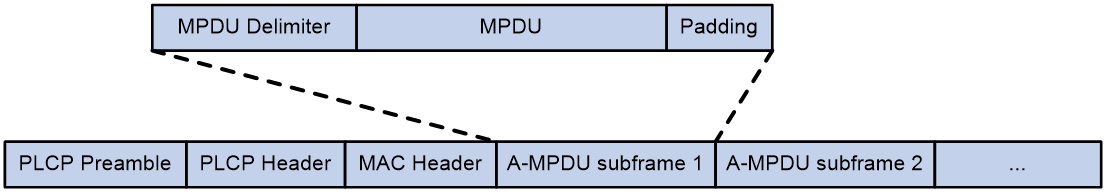
MSDU aggregation
An AP or client encapsulates a MAC Service Data Unit (MSDU) with an Ethernet header, and then converts the frame into 802.11 format for forwarding.
MSDU aggregation aggregates multiple MSDUs into one aggregate MSDU (A-MSDU) to reduce PLCP preamble, PLCP header, and MAC header overheads. This improves network throughput and frame forwarding efficiency.
All MSDUs in an A-MSDU must have the same QoS priority, source address, and destination address. When a device receives an A-MSDU, it restores the A-MSDU to multiple MSDUs for processing.
Figure 4 A-MSDU format
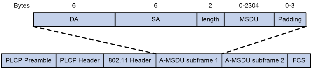
Short GI
The following matrix shows the feature and hardware compatibility:
|
Hardware series |
Model |
Short GI compatibility |
|
WA6600 series |
WA6638 |
No |
|
WA6638i |
No |
|
|
WA6636 |
No |
|
|
WA6630X |
No |
|
|
WA6628 |
No |
|
|
WA6628X |
No |
|
|
WA6628E-T |
No |
|
|
WA6622 |
No |
|
|
WA6620 |
No |
|
|
WA6620X |
No |
|
|
WA6300 series |
WA6338 |
Yes |
|
WA6338-HI |
Yes |
|
|
WA6338-LI |
Yes |
|
|
WA6330 |
Yes |
|
|
WA6330-LI |
Yes |
|
|
WA6322 |
Yes |
|
|
WA6322H |
Yes |
|
|
WA6322H-HI |
Yes |
|
|
WA6322H-LI |
Yes |
|
|
WA6320 |
Yes |
|
|
WA6320-C |
Yes |
|
|
WA6320-D |
Yes |
|
|
WA6320-SI |
Yes |
|
|
WA6320H |
Yes |
|
|
WA6320H-LI |
Yes |
|
|
WA6320H-XEPON |
Yes |
|
|
WAP922 series |
WAP922E |
Yes |
|
WAP923 series |
WAP923 |
Yes |
http://en.wikipedia.org/wiki/802.11 OFDM fragments frames to data blocks for transmission. It uses GI to ensure that the data block transmissions do not interfere with each other and are immune to transmission delays.
The GI used by 802.11a/g is 800 ns. http://en.wikipedia.org/wiki/802.11n supports a short GI of 400 ns, which provides a 10% increase in data rate.
Both the 20 MHz and 40 MHz bandwidth modes support short GI.
LDPC
802.11n introduces the Low-Density Parity Check (LDPC) mechanism to increase the signal-to-noise ratio and enhance transmission quality. LDPC takes effect only when both ends support LDPC.
STBC
The Space-Time Block Coding (STBC) mechanism enhances the reliability of data transmission and does not require clients to have high transmission rates.
MSC indexes
802.11n clients use the rate corresponding to the MCS index to send unicast frames. 802.11a/b/g clients use the 802.11a/b/g rate to send unicast frames.
The client dot11n-only feature
The client dot11n-only feature enables an AP to accept only 802.11n and 802.11ac clients. Use this feature to prevent low-speed 802.11a/b/g clients from decreasing wireless data transmission performance.
802.11n bandwidth mode
802.11n uses the channel structure of 802.11a/b/g, but it increases the number of data subchannels in each 20 MHz channel to 52. This improves data transmission rate.
802.11n binds two adjacent 20 MHz channels to form a 40 MHz channel (one primary channel and one secondary channel). This provides a simple way to double the data rate.
The bandwidth for a radio varies by bandwidth mode configuration and chip capability.
MIMO modes
The following matrix shows the feature and hardware compatibility:
|
Hardware series |
Model |
MIMO mode compatibility |
|
WA6600 series |
WA6638 |
· Radio 1: 4 × 4 · Radio 2: 4 × 4 · Radio 3: 4 × 4 |
|
WA6638i |
· Radio 1: 4 × 4 · Radio 2: 8 × 8 · Radio 3: 4 × 4 |
|
|
WA6636 |
· Radio 1: 4 × 4 · Radio 2: 2 × 2 · Radio 3: 4 × 4 |
|
|
WA6630X |
· Radio 1: 4 × 4 · Radio 2: 4 × 4 · Radio 3: 2 × 2 |
|
|
WA6628 |
· Radio 1: 8 × 8 · Radio 2: 4 × 4 |
|
|
WA6628X |
· Radio 1: 8 × 8 · Radio 2: 4 × 4 |
|
|
WA6628E-T |
· Radio 1: 8 × 8 · Radio 2: 4 × 4 |
|
|
WA6622 |
· Radio 1: 4 × 4 · Radio 2: 2 × 2 |
|
|
WA6620 |
· Radio 1: 2 × 2 · Radio 2: 2 × 2 |
|
|
WA6620X |
· Radio 1: 2 × 2 · Radio 2: 2 × 2 |
|
|
WA6300 series |
WA6338 |
· Radio 1: 4 × 4 · Radio 2: 2 × 2 · Radio 3: 2 × 2 |
|
WA6338-HI |
· Radio 1: 4 × 4 · Radio 2: 2 × 2 · Radio 3: 2 × 2 |
|
|
WA6338-LI |
· Radio 1: 4 × 4 · Radio 2: 2 × 2 · Radio 3: 2 × 2 |
|
|
WA6330 |
· Radio 1: 2 × 2 · Radio 2: 2 × 2 · Radio 3: 2 × 2 |
|
|
WA6330-LI |
· Radio 1: 2 × 2 · Radio 2: 2 × 2 · Radio 3: 1 × 1 |
|
|
WA6322 |
· Radio 1: 2 × 2 · Radio 2: 2 × 2 |
|
|
WA6322H |
· Radio 1: 2 × 2 · Radio 2: 2 × 2 |
|
|
WA6322H-HI |
· Radio 1: 2 × 2 · Radio 2: 2 × 2 |
|
|
WA6322H-LI |
· Radio 1: 2 × 2 · Radio 2: 2 × 2 |
|
|
WA6320 |
· Radio 1: 2 × 2 · Radio 2: 2 × 2 |
|
|
WA6320-C |
· Radio 1: 2 × 2 · Radio 2: 2 × 2 |
|
|
WA6320-D |
· Radio 1: 2 × 2 · Radio 2: 1 × 1 |
|
|
WA6320-SI |
· Radio 1: 2 × 2 · Radio 2: 2 × 2 |
|
|
WA6320H |
· Radio 1: 2 × 2 · Radio 2: 2 × 2 |
|
|
WA6320H-LI |
· Radio 1: 2 × 2 · Radio 2: 2 × 2 |
|
|
WA6320H-XEPON |
· Radio 1: 2 × 2 · Radio 2: 2 × 2 |
|
|
WAP922 series |
WAP922E |
· Radio 1: 2 × 2 · Radio 2: 2 × 2 |
|
WAP923 series |
WAP923 |
· Radio 1: 2 × 2 · Radio 2: 2 × 2 · Radio 3: 1 × 1 |
Multiple-input and multiple-output (MIMO) enables a radio to send and receive wireless signals through multiple spatial streams. This improves system capacity and spectrum usage without requiring higher bandwidth.
A radio can operate in one of the following MIMO modes:
· 1×1—Sends and receives wireless signals through one spatial stream.
· 2×2—Sends and receives wireless signals through two spatial streams.
· 3×3—Sends and receives wireless signals through three spatial streams.
· 4×4—Sends and receives wireless signals through four spatial streams.
· 5×5—Sends and receives wireless signals through five spatial streams.
· 6×6—Sends and receives wireless signals through six spatial streams.
· 7×7—Sends and receives wireless signals through seven spatial streams.
· 8×8—Sends and receives wireless signals through eight spatial streams.
Energy saving
The following matrix shows the feature and hardware compatibility:
|
Hardware series |
Model |
Energy saving compatibility |
|
WA6600 series |
WA6638 |
No |
|
WA6638i |
No |
|
|
WA6636 |
No |
|
|
WA6630X |
No |
|
|
WA6628 |
No |
|
|
WA6628X |
No |
|
|
WA6628E-T |
No |
|
|
WA6622 |
No |
|
|
WA6620 |
No |
|
|
WA6620X |
No |
|
|
WA6300 series |
WA6338 |
Yes |
|
WA6338-HI |
Yes |
|
|
WA6338-LI |
Yes |
|
|
WA6330 |
Yes |
|
|
WA6330-LI |
Yes |
|
|
WA6322 |
Yes |
|
|
WA6322H |
Yes |
|
|
WA6322H-HI |
Yes |
|
|
WA6322H-LI |
Yes |
|
|
WA6320 |
Yes |
|
|
WA6320-C |
Yes |
|
|
WA6320-D |
Yes |
|
|
WA6320-SI |
Yes |
|
|
WA6320H |
Yes |
|
|
WA6320H-LI |
Yes |
|
|
WA6320H-XEPON |
Yes |
|
|
WAP922 series |
WAP922E |
Yes |
|
WAP923 series |
WAP923 |
Yes |
The energy saving feature enables an AP to automatically change the MIMO mode of a radio to 1×1 if no clients associate with the radio.
802.11n protection
When both 802.11n and non-802.11n clients exist in a WLAN, transmission collision might occur because they use different modulation modes. 802.11n protection can avoid such avoidance. It enables 802.11n devices to send RTS/CTS or CTS-to-self packets to inform non-802.11n clients to defer access to the medium.
802.11n devices send RTS/CTS or CTS-to-self packets before sending data only when non-802.11n signals are detected on the channel.
802.11n protection automatically takes effect when non-802.11n clients associate with an 802.11n AP.
|
|
NOTE: 802.11n devices refer to 802.11n, 802.11ac, and 802.11ax devices. |
802.11ac functions
Based on 802.11n, 802.11ac further increases the data transmission rate and improves the network performance by providing higher bandwidth, more spatial streams, and more advanced modulation schemes.
NSSs
If the AP supports an NSS, it supports all VHT-MCS indexes for the NSS.
802.11ac clients use the rate corresponding to the VHT-MCS index for the NSS to send unicast frames. Non-802.11ac clients use the 802.11a/b/g/n rate to send unicast frames.
The client dot11ac-only feature
To prevent low-speed 802.11a/b/g/n clients from decreasing wireless data transmission performance, you can enable the client dot11ac-only feature for an AP to accept only 802.11ac clients.
802.11ac bandwidth mode
802.11ac uses the channel structure of 802.11n and increases the maximum bandwidth from 40 MHz to 160 MHz. 802.11ac can bind two adjacent 20 MHz channels to form a 40 MHz channel, bind two adjacent 40 MHz channels to form an 80 MHz channel, and bind two adjacent 80 MHz channels to form a 160 MHz channel.
Figure 5 802.11ac bandwidth modes

Configuration restrictions and guidelines
When you configure radio management, follow these restrictions and guidelines:
· When you change the mode of a radio, the system automatically adjusts the channel and power parameters for the radio.
Modifying the mode of an enabled radio logs off all associated clients.
· When you set the maximum transmit power, make sure the maximum transmit power is within the transmit power range supported by a radio.
· When you set MSC indexes for an 802.11n AP, follow these restrictions and guidelines:
¡ If you do not set a multicast MCS index, 802.11n clients and the AP use the 802.11a/b/g multicast rate to send multicast frames. If you set a multicast MCS index, one of following events occurs:
- The AP and clients use the rate corresponding to the multicast MCS index to send multicast frames if all clients are 802.11n clients.
- The AP and clients use the 802.11a/b/g multicast rate to send multicast frames if any 802.11a/b/g clients exist.
¡ When you set the maximum mandatory or supported MCS index, you are specifying a range. For example, if you set the maximum mandatory MCS index to 5, rates corresponding to MCS indexes 0 through 5 are configured as 802.11n mandatory rates.
· When you set NSSs for an 802.11ac AP, follow these restrictions and guidelines
¡ If you do not set a multicast NSS, 802.11ac clients and the AP use the 802.11a/b/g/n multicast rate to send multicast frames. If you set a multicast NSS and specify a VHT-MCS index, the following situations occur:
- The AP and clients use the rate corresponding to the VHT-MCS index for the NSS to send multicast frames if all clients are 802.11ac clients.
- The AP and clients use the 802.11a/b/g/n multicast rate to send multicast frames if any non-802.11ac clients exist.
- The maximum mandatory NSS or supported NSS determines a range of 802.11 rates. For example, if the maximum mandatory NSS is 5, rates corresponding to VHT-MCS indexes for NSSs 1 through 5 will be 802.11ac mandatory rates.
802.11ax functions
NSS
If an AP supports an NSS, it supports all HE-MCS indexes for the NSS. 802.11ax clients that use the rate corresponding to the HE-MCS index for the NSS to send unicast frames. Non-802.11ax clients use the 802.11a/b/g rate, or the rate corresponding to the MCS or VHT-MCS index for the NSS to send unicast frames.
If you do not set a multicast NSS, 802.11ax clients and the AP use the 802.11a/b/g/n/ac multicast rate to send multicast frames. If you set a multicast NSS and specify an HE-MCS index, the following situations occur:
· The AP and clients use the rate corresponding to the HE-MCS index to send multicast frames if all clients are 802.11ax clients.
· The AP and clients use the 802.11a/b/g/n/ac multicast rate to send multicast frames if any non-802.11ax clients exist.
The maximum supported NSS cannot be smaller than the maximum mandatory NSS and the multicast NSS cannot be greater than the maximum mandatory NSS.
The maximum mandatory NSS or supported NSS determines a range of 802.11 rates. For example, if the maximum mandatory NSS is 5, rates corresponding to HE-MCS indexes for NSSs 1 through 5 will be 802.11ax mandatory rates.
802.11ax bandwidth mode
802.11ax uses the channel structure of 802.11n and increases the maximum bandwidth from 40 MHz to 160 MHz. 802.11ax can bind two adjacent 20/40/80 MHz channels to form a 40/80/160 MHz channel. 802.11gax supports only the 20 MHz and 40 MHz bandwidth modes.
Figure 6 802.11ax bandwidth modes

Band navigation
Band navigation enables an AP to direct dual-band clients (2.4 GHz and 5 GHz) to the 5 GHz radio whenever possible to avoid congestion in the 2.4 GHz band. This can load balance the radios and improve network performance.
As shown in Figure 7, band navigation is enabled in the WLAN. Client 1 and Client 2 are associated with the 5 GHz radio and 2.4 GHz radio, respectively. When the dual-band client Client 3 requests to associate with the 2.4 GHz radio, the AP rejects Client 3 and directs it to the 5 GHz radio.
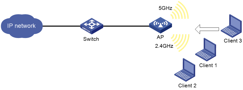
Client probing
After you enable client probing for a radio of an AP, the AP scans channels to collect client information. You can view the client information on the Monitoring > Client Proximity Sensor page.
Do not enable both WIPS and client probing.
WLAN mesh
About WLAN mesh
WLAN mesh allows APs to be wirelessly connected. The APs on a WLAN mesh network can be connected directly or over multiple hops. When one AP fails, the remaining APs can still communicate with each other. For users, a WLAN mesh network can provide the same good user experience as a traditional WLAN.
MP roles
APs on a WLAN mesh network are mesh points (MPs). MPs play the following roles:
· Single-purpose MP—Provides only mesh services.
· Mesh access point (MAP)—Provides both mesh and access services.
· Mesh portal point (MPP)—Provides a wired connection to a wired network.
Mesh profile
A mesh profile is a set of mesh protocol processing capabilities for an AP to operate on a mesh network. A mesh profile contains a mesh ID, the Authentication and Key Management mode, the backhaul rate, and the keepalive interval.
Before MPs can establish a mesh link, they need to discover each other and establish a peer relationship. MPs establish a peer relationship with each other only when their mesh profiles match.
Mesh policy
A mesh policy contains a set of mesh link setup and maintenance attributes. These attributes are the mesh link initiation feature, the probe request interval, the link rate mode, and the maximum number of mesh links. Only one mesh policy can be bound to a radio of an MP, and the policy takes effect on all mesh links on the radio.
By default, a system-defined mesh policy is bound to each radio. This system-defined mesh policy cannot be deleted or modified. To change the link setup and maintenance settings on a radio, you can bind a user-defined mesh policy to the radio to replace the system-defined mesh policy.
Mesh peer allowlist
Use a mesh peer allowlist to ensure that an MP establishes mesh links only with legitimate MPs.
An MP can establish peer relationships with any MP neighbors if you do not configure an allowlist.
WLAN multicast optimization
Overview
Multicast transmission has limitations and cannot meet the requirements for applications that are not sensitive to time delay but sensitive to data integrity. To address this issue, you can configure WLAN multicast optimization to enable an AP to convert multicast packets to unicast packets.
WLAN multicast optimization uses multicast optimization entries to manage traffic forwarding. The multicast optimization entries use the clients' MAC addresses as indexes. A multicast optimization entry records information about multicast groups that clients join, multicast sources from which clients receive traffic, multicast group version, and multicast optimization mode.
Each time a client joins a multicast group, the AP creates a multicast optimization entry for the multicast group. If multicast sources have been specified for a client when the client joins the multicast group, the AP also creates a multicast optimization entry for each multicast source. When a client leaves a multicast group or rejects a multicast source, the AP deletes the relevant multicast optimization entry for the client.
Multicast optimization policy
A multicast optimization policy defines the maximum number of clients that WLAN multicast optimization supports and defines the following actions an AP takes when the limit is reached:
· Unicast forwarding—Sends unicast packets converted from a multicast packet to only n (n equal to the specified threshold) clients that are randomly selected.
· Multicast forwarding—Forwards the multicast packet to all clients.
· Packet dropping—Drops the multicast packet.
If you do not specify an action, an AP performs unicast forwarding.
Multicast optimization entry limits
Limit for multicast optimization entries
You can limit the number of multicast optimization entries to save system resources.
When the number of multicast optimization entries reaches the limit, the AP stops creating new entries until the number falls below the limit
Limit for multicast optimization entries per client
You can limit the number of multicast optimization entries that an AP maintains for each client to prevent a client from occupying excessive system resources.
Rate limits for IGMP/MLD packets from clients
You can configure the maximum number of IGMP or MLD packets that an AP can receive from clients within the specified interval. The AP discards the excessive IGMP or MLD packets.
Bonjour gateway
Bonjour is a set of zero configuration network protocols developed by Apple Inc based on Multicast DNS (mDNS) services. Bonjour is designed to make network configuration easier for users. It enables service devices to automatically advertise service information and enables clients to automatically discover service devices without obtaining information about the devices.
However, Bonjour supports only link-local multicast addresses. To address this issue, the AP can act as a Bonjour gateway to manage clients and service devices and forward mDNS packets across VLANs. This enables Bonjour to be applied in large scale networks.
Bonjour gateway provides the following benefits:
· mDNS traffic control.
· Inter-VLAN forwarding of mDNS packets.
Bonjour service advertisement snooping and caching
As shown in Figure 8, Bonjour service advertisement snooping operates as follows:
1. Apple TV and Printer send service advertisements to advertise their service information.
2. Upon receiving the service advertisements, the Bonjour gateway caches all the service advertisements.
3. iPad requests the service of Apple TV or Printer.
4. The Bonjour gateway sends a response to iPad because the requested service is in the Bonjour cache.
Figure 8 Bonjour service advertisement snooping and caching
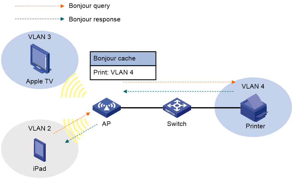
Bonjour query snooping and response
As shown in Figure 9, the Bonjour gateway performs the Bonjour query snooping and response operation by using the following process if the service query it receives is not in the Bonjour cache:
1. Upon receiving a query for the printing service from a client (iPad in the figure), the AP sends the query to the Bonjour gateway.
2. The Bonjour gateway forwards the query to the configured service VLANs because it does not find any printing service entry in the Bonjour cache.
3. The printer sends a response to the Bonjour gateway upon receiving the query.
4. The Bonjour gateway caches the response and forwards it to iPad.
Figure 9 Bonjour query snooping and response
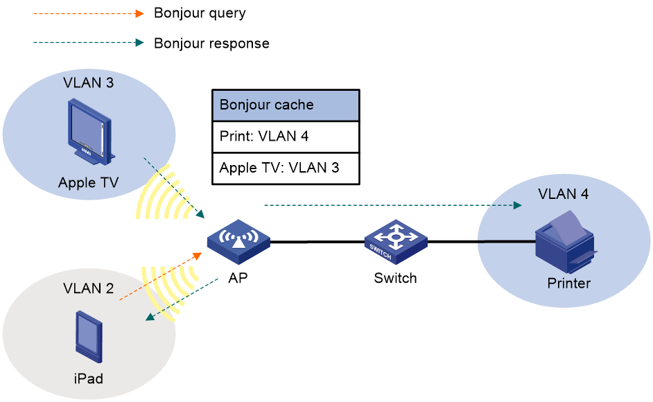
Bonjour service type
You can use the default Bonjour service types or create new Bonjour service types to control the Bonjour services that can be queried by clients. To create a Bonjour service type, you need to specify the UDP or TCP protocol and specify a description for the service type. Table 35 lists the default service types by their names and service type strings.
After you activate a Bonjour service type, the Bonjour gateway sends a query for each service of the service type if Bonjour gateway is enabled globally.
When you activate a Bonjour service type, you can specify the maximum number of service entries for the service type. If you do not specify this limit, the number of service entries for the service type is not limited.
When you deactivate a service type, all service entries of the service type are removed.
Table 35 Apple Bonjour protocols and service type strings
|
Name |
Service type strings |
|
afpovertcp |
AppleTalkFiling Protocol |
|
airplay |
Airplay |
|
airport |
Airport Base Station |
|
apple-sasl |
Apple Password Server |
|
daap |
Digital Audio Access Protocol |
|
dacp |
Digital Audio Control Protocol |
|
distcc |
Distributed Compiler |
|
dpap |
Digital Photo Access Protocol |
|
eppc |
Remote AppleEvents |
|
ftp |
File Transfer Protocol |
|
http |
Hypertext Transfer Protocol |
|
ica-networking |
Image Capture Sharing |
|
ichat |
iChat Instant Messaging Protocol |
|
ipp |
Internet Printing Protocol over HTTP |
|
ipps |
Internet Printing Protocol over HTTPS |
|
nfs |
Network File System |
|
pdl-stream |
PDL Data Stream |
|
printer |
Line Printer Daemon |
|
raop |
Remote Audio Output Protocol |
|
riousbprint |
Remote I/O USB Printer Protocol |
|
servermgr |
Server Admin |
|
ssh |
Secure Shell |
|
telnet |
Remote Login |
|
webdav |
WebDav File System |
|
workstation |
Workgroup Manager |
|
xserveraid |
Xerver RAID |
Bonjour policy
You can apply a Bonjour policy to a user profile, AP, AP group, interface, or wireless service to manage the service types and service VLANs.
Service type
This feature enables the Bonjour gateway to forward queries and service advertisements according to the following rules:
· For a query, if the service type in the query does not match the specified service type, the Bonjour gateway discards the query.
· For a service advertisement, the Bonjour gateway forwards it only when it matches all the configured options.
Service VLAN
The Bonjour gateway forwards queries and service advertisements only to the VLANs in the specified VLAN list.
You can also enable the Bonjour gateway to forward queries and responses to the VLANs to which the clients belong.
Network security
Packet filtering
You can apply an ACL to an interface to filter and take corresponding actions on incoming or outgoing packets. Packets that do not match any ACL rules are processed based on the default action.
QoS
QoS policies
In data communications, Quality of Service (QoS) provides differentiated service guarantees for diversified traffic in terms of bandwidth, delay, jitter, and drop rate, all of which can affect QoS.
By associating a traffic behavior with a traffic class in a QoS policy, you apply QoS actions in the traffic behavior to the traffic class.
Traffic class
A traffic class defines a set of match criteria for classifying traffic.
Traffic behavior
A traffic behavior defines a set of QoS actions to take on packets.
QoS policy
A QoS policy associates traffic classes with traffic behaviors and performs the actions in each behavior on its associated traffic class.
Applying a QoS policy
You can apply a QoS policy to an interface. The QoS policy takes effect on the traffic sent or received on the interface. A QoS policy can be applied to multiple interfaces, but each direction of an interface can be configured with only one QoS policy. The QoS policy applied to the outgoing traffic on an interface or PVC does not regulate local packets. Local packets refer to critical protocol packets sent by the local system for operation maintenance. The most common local packets include link maintenance, routing, LDP, RSVP, and SSH packets.
Priority mapping
When a packet arrives, a device assigns values of priority parameters to the packet.
Priority mapping allows you to modify the priority values of the packet according to priority mapping rules. The priority parameters decide the scheduling priority and forwarding priority of the packet.
Port priority
When a port is configured with a priority trust mode, the device trusts the priorities included in incoming packets. The device can automatically resolves the priorities or flag bits included in packets. The device then maps the trusted priority to the target priority types and values according to the priority maps.
When a port is not configured with a priority trust mode and is configured with a port priority, the device does not trust the priorities included in incoming packets. The device uses its port priority to look for priority parameters for the incoming packets.
The available priority trust modes include the following types:
· Untrust—Does not trust any priority included in packets.
· Dot1p—Trusts the 802.1p priorities included in packets.
· DSCP—Trusts the DSCP priorities included in IP packets.
Priority map
The device provides the dot11e-lp, dot1p-lp, dscp-lp, lp-dot11e, lp-dot1p, and lp-dscp priority maps.
If a default priority map cannot meet your requirements, you can modify the priority map as required.
802.1X
See 802.1X in System features.
ISP domains
See ISP domains in System features.
RADIUS
See RADIUS in System features.
Local users
See local users in System features.
MAC authentication
MAC authentication controls network access by authenticating source MAC addresses on a port. The feature does not require client software, and users do not have to enter a username and password for network access. The device initiates a MAC authentication process when it detects an unknown source MAC address on a MAC authentication-enabled port. If the MAC address passes authentication, the user can access authorized network resources. If the authentication fails, the device marks the MAC address as a silent MAC address, drops the packet, and starts a quiet timer. The device drops all subsequent packets from the MAC address within the quiet time. The quiet mechanism avoids repeated authentication during a short time.
Port security
Port security combines and extends 802.1X and MAC authentication to provide MAC-based network access control.
Port security provides the following functions:
· Prevents unauthorized access to a network by checking the source MAC address of inbound traffic.
· Prevents access to unauthorized devices or hosts by checking the destination MAC address of outbound traffic.
· Controls MAC address learning and authentication on a port to ensure that the port learns only source trusted MAC addresses.
A frame is illegal if its source MAC address cannot be learned in a port security mode or it is from a client that has failed 802.1X or MAC authentication. The port security feature automatically takes a predefined action on illegal frames. This automatic mechanism enhances network security and reduces human intervention.
Portal
Portal authentication controls user access to networks. Portal authenticates a user by the username and password the user enters on a portal authentication page. Typically, portal authentication is deployed on the access layer and vital data entries.
In a portal-enabled network, users can actively initiate portal authentication by visiting the authentication website provided by the portal Web server. Or, they are redirected to the portal authentication page for authentication when they visit other websites.
The device supports Portal 1.0, Portal 2.0, and Portal 3.0.
Portal system
A typical portal system contains these basic components: access device, portal authentication server, portal Web server, and AAA server.
Access device
An access device provides access services. It has the following functions:
· Redirects all HTTP or HTTPS requests of unauthenticated users to the portal Web server.
· Interacts with the portal authentication server and the AAA server to complete authentication, authorization, and accounting.
· Allows users that pass portal authentication to access authorized network resources.
Portal server
A portal server collectively refers to a portal authentication server and portal Web server.
The portal Web server pushes the Web authentication page to authentication clients and forwards user authentication information (username and password) to the portal authentication server. The portal authentication server receives authentication requests from authentication clients and interacts with the access device to authenticate users. The portal Web server is typically integrated with the portal authentication server and it can also be an independent server.
AAA server
The AAA server interacts with the access device to implement authentication, authorization, accounting for portal users. In a portal system, a RADIUS server can perform authentication, authorization, accounting for portal users, and an LDAP server can perform authentication for portal users.
Local portal service
An access device can act as both a portal Web server and a portal authentication server to provide the local portal Web service for authentication clients.
Preauthentication IP address pool
You must specify a preauthentication IP address pool on a portal-enabled interface in the following situation:
· Portal users access the network through a subinterface of the portal-enabled interface.
· The subinterface does not have an IP address.
· Portal users need to obtain IP addresses through DHCP.
After a user connects to a portal-enabled interface, the user uses an IP address for portal authentication according to the following rules:
· If the interface is configured with a preauthentication IP address pool, the user uses the following IP address:
¡ If the client is configured to obtain an IP address automatically through DHCP, the user obtains an address from the specified IP address pool.
¡ If the client is configured with a static IP address, the user uses the static IP address.
· If the interface has an IP address but no preauthentication IP pool specified, the user uses the static IP address or the IP address obtained from a DHCP server.
· If the interface has no IP address or preauthentication IP pool specified, the user cannot perform portal authentication.
After the user passes portal authentication, the AAA server authorizes an IP address pool for re-assigning an IP address to the user. If no authorized IP address pool is deployed, the user continues using the previous IP address.
Portal authentication domain
An authentication domain defines a set of authentication, authorization, and accounting policies. Each portal user belongs to an authentication domain and is authenticated, authorized, and accounted in the domain.
With an authentication domain specified on an interface or service template, the device uses the authentication domain for AAA of portal users. This allows for flexible portal access control.
System
Resources
See ACL and time range in System features.
Cloud connections
The following matrix shows the feature and hardware compatibility:
|
Hardware series |
Model |
Cloud connection compatibility |
|
WA6600 series |
WA6638 |
Yes |
|
WA6638i |
Yes |
|
|
WA6636 |
Yes |
|
|
WA6630X |
Yes |
|
|
WA6628 |
Yes |
|
|
WA6628X |
Yes |
|
|
WA6628E-T |
No |
|
|
WA6622 |
Yes |
|
|
WA6620 |
Yes |
|
|
WA6620X |
Yes |
|
|
WA6300 series |
WA6338 |
Yes |
|
WA6338-HI |
Yes |
|
|
WA6338-LI |
Yes |
|
|
WA6330 |
Yes |
|
|
WA6330-LI |
Yes |
|
|
WA6322 |
Yes |
|
|
WA6322H |
Yes |
|
|
WA6322H-HI |
Yes |
|
|
WA6322H-LI |
Yes |
|
|
WA6320 |
Yes |
|
|
WA6320-C |
Yes |
|
|
WA6320-D |
Yes |
|
|
WA6320-SI |
Yes |
|
|
WA6320H |
Yes |
|
|
WA6320H-LI |
Yes |
|
|
WA6320H-XEPON |
Yes |
|
|
WAP922 series |
WAP922E |
Yes |
|
WAP923 series |
WAP923 |
Yes |
Cloud connections
You can configure the domain name of the cloud server on a device to enable the device to establish a cloud connection to the cloud server. Then, you can manage the device remotely.
Device unbinding
You can unbind a device from the cloud server by using a verification code.
Tools
RF Ping
The following matrix shows the feature and hardware compatibility:
|
Hardware series |
Model |
RF ping compatibility |
|
WA6600 series |
WA6638 |
Yes |
|
WA6638i |
||
|
WA6636 |
||
|
WA6630X |
||
|
WA6628 |
||
|
WA6628X |
||
|
WA6628E-T |
||
|
WA6622 |
||
|
WA6620 |
||
|
WA6620X |
||
|
WA6300 series |
WA6338 |
No |
|
WA6338-HI |
||
|
WA6338-LI |
||
|
WA6330 |
||
|
WA6330-LI |
||
|
WA6322 |
||
|
WA6322H |
||
|
WA6322H-HI |
||
|
WA6322H-LI |
||
|
WA6320 |
||
|
WA6320-C |
||
|
WA6320-D |
||
|
WA6320-SI |
||
|
WA6320H |
||
|
WA6320H-LI |
||
|
WA6320H-XEPON |
||
|
WAP922 series |
WAP922E |
No |
|
WAP923 series |
WAP923 |
No |
RF Ping, which is also known as wireless link quality detection, enables an AP to test the quality of the link to a wireless client. The AP sends five empty data frames to the client at each supported rate. Then it calculates link quality information such as RSSI, packet retransmissions, and Round-trip Time (RTT) based on the responses from the client.
Debugging
The system provides diagnostic information collection to help users in troubleshooting.