- Table of Contents
-
- H3C SR6600&SR6600-X Routers Configuration Examples-6W100
- 00-Preface
- 01-H3C SR6600&SR6600-X Routers Basic MPLS Configuration Examples
- 02-H3C SR6600&SR6600-X Routers BGP Configuration Examples
- 03-H3C SR6600&SR6600-X Routers Ethernet Link Aggregation Configuration Examples
- 04-H3C SR6600&SR6600-X Routers IPv6 IS-IS Configuration Examples
- 05-H3C SR6600&SR6600-X Routers IS-IS Configuration Examples
- 06-H3C SR6600&SR6600-X Routers OSPF Configuration Examples
- 07-H3C SR6600&SR6600-X Routers OSPFv3 Configuration Examples
- 08-H3C SR6600&SR6600-X Routers Policy-Based Routing Configuration Examples
- 09-H3C SR6600&SR6600-X Routers PPP Configuration Examples
- 10-H3C SR6600&SR6600-X Routers RBAC Configuration Examples
- Related Documents
-
| Title | Size | Download |
|---|---|---|
| 01-H3C SR6600&SR6600-X Routers Basic MPLS Configuration Examples | 154.27 KB |
|
|
|
H3C SR6600&SR6600-X Routers |
|
Basic MPLS Configuration Examples |
|
|
|
|
SR6600 Router Series
SR6600-X Router Series
Copyright © 2017 New H3C Technologies Co., Ltd. All rights reserved.
No part of this manual may be reproduced or transmitted in any form or by any means without prior written consent of New H3C Technologies Co., Ltd.
Except for the trademarks of New H3C Technologies Co., Ltd., any trademarks that may be mentioned in this document are the property of their respective owners.
The information in this
document is subject to change without notice.
Contents
Example: Configuring static LSPs
Configuration restrictions and guidelines
Introduction
This document provides static LSP and LDP LSP configuration examples.
The following table shows the differences between a static LSP and an LDP LSP:
|
LSP type |
Establishment |
Feature |
Application scenario |
|
Static LSP |
You establish a static LSP by specifying the incoming and outgoing labels on ingress, transit, and egress nodes of the forwarding path. |
· Consumes fewer resources. · Cannot automatically adapt to network topology changes. |
Small and stable networks with simple topologies. |
|
LDP LSP |
You establish an LDP LSP by configuring MPLS LDP. LDP classifies FECs, distributes FEC-label mappings, and establishes and maintains LSPs. |
· Consumes more resources. · Automatically adapts to network topology changes. |
Large and unstable networks with complicated topologies. |
Prerequisites
This document is not restricted to specific software or hardware versions.
The configuration examples in this document were created and verified in a lab environment, and all the devices were started with the factory default configuration. When you are working on a live network, make sure you understand the potential impact of every command on your network.
This document assumes that you have basic knowledge of MPLS and LDP.
Example: Configuring static LSPs
Network requirements
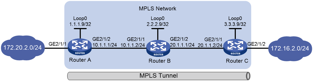
As shown in Figure 1, establish static LSPs between Router A and Router C to allow communication between subnets 172.20.2.0/24 and 172.16.2.0/24 over the MPLS network.
Requirements analysis
To meet the network requirements, you must perform the following tasks:
· LSPs are unidirectional. To ensure that data can be bidirectionally forwarded, configure an LSP for each direction of the data forwarding path, and specify the ingress, transit, and egress nodes for each LSP.
· To direct traffic to an LSP for MPLS forwarding, make sure the ingress node has a route to the FEC destination of the LSP. This example uses a static route. Route configuration is not needed on the transit and egress nodes.
Software version used
This configuration example was created and verified on R7607.
Configuration restrictions and guidelines
When you configure a static LSP, follow these restrictions and guidelines:
· Make sure the outgoing label specified on an LSR is the same as the incoming label specified on the directly connected downstream LSR.
· If you configure a static IP route for the LSP, specify the same next hop or outgoing interface for the static route and the static LSP.
· On the ingress or transit node of the static LSP, do not specify the public address of a local interface as the next hop address of the static LSP.
· MPLS adds a label or multiple labels to packets. After MPLS is enabled on an interface, configure jumboframe support on the interface to avoid MPLS packet dropping when the packet size exceeds the interface MPU.
Configuration procedures
1. Configure IP addresses and masks for interfaces, including the loopback interfaces, as shown in Figure 1. (Details not shown.)
2. Configure a static route to the destination address of each LSP:
# Configure a static route to the FEC destination of the LSP from Router A to Router C.
<RouterA> system-view
[RouterA] ip route-static 172.16.2.1 24 10.1.1.2
# Configure a static route to the FEC destination of the LSP from Router C to Router A.
<RouterC> system-view
[RouterC] ip route-static 172.20.2.1 24 20.1.1.1
# Verify that the static route has been created on the ingress nodes, for example, on Router A.
[RouterA] display ip routing-table
Destinations : 18 Routes : 18
Destination/Mask Proto Pre Cost NextHop Interface
0.0.0.0/32 Direct 0 0 127.0.0.1 InLoop0
1.1.1.9/32 Direct 0 0 127.0.0.1 InLoop0
10.1.1.0/24 Direct 0 0 10.1.1.1 GE2/1/2
10.1.1.0/32 Direct 0 0 10.1.1.1 GE2/1/2
10.1.1.1/32 Direct 0 0 127.0.0.1 InLoop0
10.1.1.255/32 Direct 0 0 10.1.1.1 GE2/1/2
127.0.0.0/8 Direct 0 0 127.0.0.1 InLoop0
127.0.0.0/32 Direct 0 0 127.0.0.1 InLoop0
127.0.0.1/32 Direct 0 0 127.0.0.1 InLoop0
127.255.255.255/32 Direct 0 0 127.0.0.1 InLoop0
172.16.2.0/24 Static 60 0 10.1.1.2 GE2/1/2
172.20.2.0/24 Direct 0 0 172.20.2.1 GE2/1/1
172.20.2.0/32 Direct 0 0 172.20.2.1 GE2/1/1
172.20.2.1/32 Direct 0 0 127.0.0.1 InLoop0
172.20.2.255/32 Direct 0 0 172.20.2.1 GE2/1/1
224.0.0.0/4 Direct 0 0 0.0.0.0 NULL0
224.0.0.0/24 Direct 0 0 0.0.0.0 NULL0
255.255.255.255/32 Direct 0 0 127.0.0.1 InLoop0
3. Configure basic MPLS on the routers:
# Configure Router A.
[RouterA] mpls lsr-id 1.1.1.9
[RouterA] interface gigabitethernet 2/1/2
[RouterA-GigabitEthernet2/1/2] mpls enable
[RouterA-GigabitEthernet2/1/2] quit
# Configure Router B.
[RouterB] mpls lsr-id 2.2.2.9
[RouterB] interface gigabitethernet 2/1/1
[RouterB-GigabitEthernet2/1/1] mpls enable
[RouterB-GigabitEthernet2/1/1] quit
[RouterB] interface gigabitethernet 2/1/2
[RouterB-GigabitEthernet2/1/2] mpls enable
[RouterB-GigabitEthernet2/1/2] quit
# Configure Router C.
[RouterC] mpls lsr-id 3.3.3.9
[RouterC] interface gigabitethernet 2/1/1
[RouterC-GigabitEthernet2/1/1] mpls enable
[RouterC-GigabitEthernet2/1/1] quit
4. Configure a static LSP from Router A to Router C:
# Configure the ingress node Router A. Specify the LSP name as AtoC, destination address as 172.16.2.1/24, next hop as 10.1.1.2, and outgoing label as 30.
[RouterA] static-lsp ingress AtoC destination 172.16.2.1 24 nexthop 10.1.1.2 out-label 30
# Configure the transit node Router B. Specify the LSP name as AtoC, incoming label as 30, next hop as 20.1.1.2, and outgoing label as 50.
[RouterB] static-lsp transit AtoC in-label 30 nexthop 20.1.1.2 out-label 50
# Configure the egress node Router C. Specify the LSP name as AtoC and incoming label as 50.
[RouterC] static-lsp egress AtoC in-label 50
5. Configure a static LSP from Router C to Router A:
# Configure the ingress node Router C. Specify the LSP name as CtoA, destination address as 172.20.2.1/24, next hop as 20.1.1.1, and outgoing label as 40.
[RouterC] static-lsp ingress CtoA destination 172.20.2.1 24 nexthop 20.1.1.1 out-label 40
# Configure the transit node Router B. Specify the LSP name as CtoA, incoming label as 40, next hop as 10.1.1.1, and outgoing label as 70.
[RouterB] static-lsp transit CtoA in-label 40 nexthop 10.1.1.1 out-label 70
# Configure the egress node Router A. Specify the LSP name as CtoA and incoming label as 70.
[RouterA] static-lsp egress CtoA in-label 70
Verifying the configuration
# Display static LSP information on routers, for example, on Router A.
[RouterA] display mpls static-lsp
Total: 2
Name FEC In/Out Label Nexthop/Out Interface State
AtoC 172.16.2.0/24 NULL/30 10.1.1.2 Up
CtoA -/- 70/NULL - Up
# Test the connectivity of the LSP from Router A to Router C.
[RouterA] ping mpls -a 172.20.2.1 ipv4 172.16.2.0 24
MPLS ping FEC 172.16.2.0/24 with 100 bytes of data:
100 bytes from 20.1.1.2: Sequence=1 time=3 ms
100 bytes from 20.1.1.2: Sequence=2 time=2 ms
100 bytes from 20.1.1.2: Sequence=3 time=2 ms
100 bytes from 20.1.1.2: Sequence=4 time=2 ms
100 bytes from 20.1.1.2: Sequence=5 time=27 ms
--- Ping statistics for FEC 172.16.2.0/24 ---
5 packets transmitted, 5 packets received, 0.0% packet loss
Round-trip min/avg/max = 2/7/27 ms
# Test the connectivity of the LSP from Router C to Router A.
[RouterC] ping mpls -a 172.16.2.1 ipv4 172.20.2.0 24
MPLS ping FEC 172.20.2.0/24 with 100 bytes of data:
100 bytes from 10.1.1.1: Sequence=1 time=3 ms
100 bytes from 10.1.1.1: Sequence=2 time=2 ms
100 bytes from 10.1.1.1: Sequence=3 time=2 ms
100 bytes from 10.1.1.1: Sequence=4 time=2 ms
100 bytes from 10.1.1.1: Sequence=5 time=27 ms
--- Ping statistics for FEC 172.20.2.0/24 ---
5 packets transmitted, 5 packets received, 0.0% packet loss
Round-trip min/avg/max = 2/7/27 ms
Configuration files
· Router A:
#
mpls lsr-id 1.1.1.9
#
interface LoopBack0
ip address 1.1.1.9 255.255.255.255
#
interface GigabitEthernet2/1/1
port link-mode route
ip address 172.20.2.1 255.255.255.0
#
interface GigabitEthernet2/1/2
port link-mode route
ip address 10.1.1.1 255.255.255.0
mpls enable
#
ip route-static 172.16.2.0 24 10.1.1.2
#
static-lsp ingress AtoC destination 172.16.2.0 24 nexthop 10.1.1.2 out-label 30
static-lsp egress CtoA in-label 70
· Router B:
#
mpls lsr-id 2.2.2.9
#
interface LoopBack0
ip address 2.2.2.9 255.255.255.255
#
interface GigabitEthernet2/1/1
port link-mode route
ip address 10.1.1.2 255.255.255.0
mpls enable
#
interface GigabitEthernet2/1/2
port link-mode route
ip address 20.1.1.1 255.255.255.0
mpls enable
#
static-lsp transit AtoC in-label 30 nexthop 20.1.1.2 out-label 50
static-lsp transit CtoA in-label 40 nexthop 10.1.1.1 out-label 70
· Router C:
#
mpls lsr-id 3.3.3.9
#
interface LoopBack0
ip address 3.3.3.9 255.255.255.255
#
interface GigabitEthernet2/1/1
port link-mode route
ip address 20.1.1.2 255.255.255.0
mpls enable
#
interface GigabitEthernet2/1/2
port link-mode route
ip address 172.16.2.1 255.255.255.0
#
ip route-static 172.20.2.1 255.255.255.0 20.1.1.1
#
static-lsp ingress CtoA destination 172.20.2.0 24 nexthop 20.1.1.1 out-label 40
static-lsp egress AtoC in-label 50
Example: Configuring LDP LSPs
Network requirements
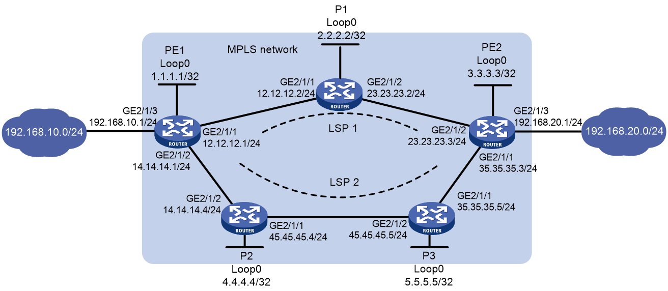
As shown in Figure 2, two paths are available for PE 1 and PE 2 to communicate with each other.
· Configure LDP to establish LSPs between PE 1 and PE 2 to allow communication between subnets 192.168.10.0/24 and 192.168.20.0/24 over the MPLS network.
¡ Use LSP 1 as the primary path.
¡ Use LSP 2 as the backup path, which takes over LSP 1 when LSP 1 fails.
· Configure LDP to establish LSPs only for destinations 1.1.1.1/32, 2.2.2.2/32, 3.3.3.3/32, 4.4.4.4/32, 5.5.5.5/32, 192.168.10.0/24, and 192.168.20.0/24.
Requirements analysis
To meet the network requirements, you must perform the following tasks:
· To establish LDP LSPs, configure a routing protocol to ensure IP connectivity among the devices. This example uses OSPF.
· To use LSP 1 as the primary path and LSP 2 as the backup, configure the routes for LSP 1 and LSP 2 as the primary and backup routes, respectively. This example uses OSPF. The OSPF cost of the route for LSP 1 is smaller than that for LSP 2. Therefore, LSP 1 is used when it is available.
· To control LSP establishment, configure LSP generation policies on each LSR.
Software version used
This configuration example was created and verified on R7607.
Configuration procedures
1. Configure IP addresses and masks for interfaces, including the loopback interfaces, as shown in Figure 2. (Details not shown.)
2. Configure OSPF on each router to ensure IP connectivity:
# Configure PE 1.
[PE1] ospf
[PE1-ospf-1] area 0
[PE1-ospf-1-area-0.0.0.0] network 1.1.1.1 0.0.0.0
[PE1-ospf-1-area-0.0.0.0] network 12.12.12.0 0.0.0.255
[PE1-ospf-1-area-0.0.0.0] network 14.14.14.0 0.0.0.255
[PE1-ospf-1-area-0.0.0.0] network 192.168.10.0 0.0.0.255
[PE1-ospf-1-area-0.0.0.0] quit
[PE1-ospf-1] quit
# Configure P 1.
[P1] ospf
[P1-ospf-1] area 0
[P1-ospf-1-area-0.0.0.0] network 2.2.2.2 0.0.0.0
[P1-ospf-1-area-0.0.0.0] network 12.12.12.0 0.0.0.255
[P1-ospf-1-area-0.0.0.0] network 23.23.23.0 0.0.0.255
[P1-ospf-1-area-0.0.0.0] quit
[P1-ospf-1] quit
# Configure P 2.
[P2] ospf
[P2-ospf-1] area 0
[P2-ospf-1-area-0.0.0.0] network 4.4.4.4 0.0.0.0
[P2-ospf-1-area-0.0.0.0] network 14.14.14.0 0.0.0.255
[P2-ospf-1-area-0.0.0.0] network 45.45.45.0 0.0.0.255
[P2-ospf-1-area-0.0.0.0] quit
[P2-ospf-1] quit
# Configure P 3.
[P3] ospf
[P3-ospf-1] area 0
[P3-ospf-1-area-0.0.0.0] network 5.5.5.5 0.0.0.0
[P3-ospf-1-area-0.0.0.0] network 45.45.45.0 0.0.0.255
[P3-ospf-1-area-0.0.0.0] network 35.35.35.0 0.0.0.255
[P3-ospf-1-area-0.0.0.0] quit
[P3-ospf-1] quit
# Configure PE 2.
[PE2] ospf
[PE2-ospf-1] area 0
[PE2-ospf-1-area-0.0.0.0] network 3.3.3.3 0.0.0.0
[PE2-ospf-1-area-0.0.0.0] network 23.23.23.0 0.0.0.255
[PE2-ospf-1-area-0.0.0.0] network 35.35.35.0 0.0.0.255
[PE2-ospf-1-area-0.0.0.0] network 192.168.20.0 0.0.0.255
[PE2-ospf-1-area-0.0.0.0] quit
[PE2-ospf-1] quit
# On each router, for example, on PE 1, verify that the routers have learned the routes to each other.
[PE1] display ospf routing
OSPF Process 1 with Router ID 1.1.1.1
Routing Table
Routing for network
Destination Cost Type NextHop AdvRouter Area
45.45.45.0/24 2 Transit 14.14.14.4 5.5.5.5 0.0.0.0
35.35.35.0/24 3 Transit 14.14.14.4 5.5.5.5 0.0.0.0
35.35.35.0/24 3 Transit 12.12.12.2 5.5.5.5 0.0.0.0
192.168.10.0/24 1 Stub 192.168.10.1 1.1.1.1 0.0.0.0
5.5.5.5/32 2 Stub 14.14.14.4 5.5.5.5 0.0.0.0
14.14.14.0/24 1 Transit 14.14.14.1 4.4.4.4 0.0.0.0
23.23.23.0/24 2 Transit 12.12.12.2 3.3.3.3 0.0.0.0
4.4.4.4/32 1 Stub 14.14.14.4 4.4.4.4 0.0.0.0
3.3.3.3/32 2 Stub 12.12.12.2 3.3.3.3 0.0.0.0
12.12.12.0/24 1 Transit 12.12.12.1 2.2.2.2 0.0.0.0
2.2.2.2/32 1 Stub 12.12.12.2 2.2.2.2 0.0.0.0
1.1.1.1/32 0 Stub 1.1.1.1 1.1.1.1 0.0.0.0
192.168.20.0/24 3 Stub 12.12.12.2 3.3.3.3 0.0.0.0
# On each router, for example, on PE 1, verify that OSPF neighbor relationships in Full state have been established between PE 1, P devices, and PE 2.
[PE1] display ospf peer verbose
OSPF Process 1 with Router ID 1.1.1.1
Neighbors
Area 0.0.0.0 interface 14.14.14.1(GigabitEthernet2/1/2)'s neighbors
Router ID: 4.4.4.4 Address: 14.14.14.4 GR state: Normal
State: Full Mode: Nbr is master Priority: 1
DR: 14.14.14.4 BDR: 14.14.14.1 MTU: 0
Options is 0x42 (-|O|-|-|-|-|E|-)
Dead timer due in 40 sec
Neighbor is up for 00:03:30
Authentication Sequence: [ 0 ]
Neighbor state change count: 6
BFD status: Disabled
Neighbors
Area 0.0.0.0 interface 12.12.12.1(GigabitEthernet2/1/1)'s neighbors
Router ID: 2.2.2.2 Address: 12.12.12.2 GR state: Normal
State: Full Mode: Nbr is master Priority: 1
DR: 12.12.12.2 BDR: 12.12.12.1 MTU: 0
Options is 0x42 (-|O|-|-|-|-|E|-)
Dead timer due in 36 sec
Neighbor is up for 00:03:24
Authentication Sequence: [ 0 ]
Neighbor state change count: 6
BFD status: Disabled
Last Neighbor Down Event:
Router ID: 4.4.4.4
Local Address: 14.14.14.1
Remote Address: 14.14.14.4
Time: May 14 09:07:19 2017
Reason: Reset ospf command was performed
3. Configure basic MPLS and MPLS LDP:
# Configure PE 1.
[PE1] mpls lsr-id 1.1.1.1
[PE1] mpls ldp
[PE1-ldp] quit
[PE1] interface gigabitethernet 2/1/1
[PE1-GigabitEthernet2/1/1] mpls enable
[PE1-GigabitEthernet2/1/1] mpls ldp enable
[PE1-GigabitEthernet2/1/1] quit
[PE1] interface gigabitethernet 2/1/2
[PE1-GigabitEthernet2/1/2] mpls enable
[PE1-GigabitEthernet2/1/2] mpls ldp enable
[PE1-GigabitEthernet2/1/2] quit
# Configure P 1.
[P1] mpls lsr-id 2.2.2.2
[P1] mpls ldp
[P1-ldp] quit
[P1] interface gigabitethernet 2/1/1
[P1-GigabitEthernet2/1/1] mpls enable
[P1-GigabitEthernet2/1/1] mpls ldp enable
[P1-GigabitEthernet2/1/1] quit
[P1] interface gigabitethernet 2/1/2
[P1-GigabitEthernet2/1/2] mpls enable
[P1-GigabitEthernet2/1/2] mpls ldp enable
[P1-GigabitEthernet2/1/2] quit
# Configure P 2.
[P2] mpls lsr-id 4.4.4.4
[P2] mpls ldp
[P2-ldp] quit
[P2] interface gigabitethernet 2/1/1
[P2-GigabitEthernet2/1/1] mpls enable
[P2-GigabitEthernet2/1/1] mpls ldp enable
[P2-GigabitEthernet2/1/1] quit
[P2] interface gigabitethernet 2/1/2
[P2-GigabitEthernet2/1/2] mpls enable
[P2-GigabitEthernet2/1/2] mpls ldp enable
[P2-GigabitEthernet2/1/2] quit
# Configure P 3.
[P3] mpls lsr-id 5.5.5.5
[P3] mpls ldp
[P3-ldp] quit
[P3] interface gigabitethernet 2/1/1
[P3-GigabitEthernet2/1/1] mpls enable
[P3-GigabitEthernet2/1/1] mpls ldp enable
[P3-GigabitEthernet2/1/1] quit
[P3] interface gigabitethernet 2/1/2
[P3-GigabitEthernet2/1/2] mpls enable
[P3-GigabitEthernet2/1/2] mpls ldp enable
[P3-GigabitEthernet2/1/2] quit
# Configure PE 2.
[PE2] mpls lsr-id 3.3.3.3
[PE2] mpls ldp
[PE2-mpls-ldp] quit
[PE2] interface gigabitethernet 2/1/1
[PE2-GigabitEthernet2/1/1] mpls enable
[PE2-GigabitEthernet2/1/1] mpls ldp enable
[PE2-GigabitEthernet2/1/1] quit
[PE2] interface gigabitethernet 2/1/2
[PE2-GigabitEthernet2/1/2] mpls enable
[PE2-GigabitEthernet2/1/2] mpls ldp enable
[PE2-GigabitEthernet2/1/2] quit
# On each router, for example, on PE 1, verify that LDP sessions in Operational state have been established between PE 1, P devices, and PE 2.
[PE1] display mpls ldp peer
Total number of peers: 2
Peer LDP ID State Role GR MD5 KA Sent/Rcvd
2.2.2.2:0 Operational Passive Off Off 55/55
4.4.4.4:0 Operational Passive Off Off 6/6
4. Configure LSP generation policies:
# On PE 1, create IP prefix list PE1, and configure LDP to use only the routes permitted by the prefix list to establish LSPs.
[PE1] ip prefix-list PE1 index 10 permit 1.1.1.1 32
[PE1] ip prefix-list PE1 index 20 permit 2.2.2.2 32
[PE1] ip prefix-list PE1 index 30 permit 3.3.3.3 32
[PE1] ip prefix-list PE1 index 40 permit 4.4.4.4 32
[PE1] ip prefix-list PE1 index 50 permit 5.5.5.5 32
[PE1] ip prefix-list PE1 index 60 permit 192.168.10.0 24
[PE1] ip prefix-list PE1 index 70 permit 192.168.20.0 24
[PE1] mpls ldp
[PE1-ldp] lsp-trigger prefix-list PE1
[PE1-ldp] quit
# On P 1, create IP prefix list P1, and configure LDP to use only the routes permitted by the prefix list to establish LSPs.
[P1] ip prefix-list P1 index 10 permit 1.1.1.1 32
[P1] ip prefix-list P1 index 20 permit 2.2.2.2 32
[P1] ip prefix-list P1 index 30 permit 3.3.3.3 32
[P1] ip prefix-list P1 index 40 permit 4.4.4.4 32
[P1] ip prefix-list P1 index 50 permit 5.5.5.5 32
[P1] ip prefix-list P1 index 60 permit 192.168.10.0 24
[P1] ip prefix-list P1 index 70 permit 192.168.20.0 24
[P1] mpls ldp
[P1-ldp] lsp-trigger prefix-list P1
[P1-ldp] quit
# On P 2, create IP prefix list P2, and configure LDP to use only the routes permitted by the prefix list to establish LSPs.
[P2] ip prefix-list P2 index 10 permit 1.1.1.1 32
[P2] ip prefix-list P2 index 20 permit 2.2.2.2 32
[P2] ip prefix-list P2 index 30 permit 3.3.3.3 32
[P2] ip prefix-list P2 index 40 permit 4.4.4.4 32
[P2] ip prefix-list P2 index 50 permit 5.5.5.5 32
[P2] ip prefix-list P2 index 60 permit 192.168.10.0 24
[P2] ip prefix-list P2 index 70 permit 192.168.20.0 24
[P2] mpls ldp
[P2-ldp] lsp-trigger prefix-list P2
[P2-ldp] quit
# On P 3, create IP prefix list P3, and configure LDP to use only the routes permitted by the prefix list to establish LSPs.
[P3] ip prefix-list P3 index 10 permit 1.1.1.1 32
[P3] ip prefix-list P3 index 20 permit 2.2.2.2 32
[P3] ip prefix-list P3 index 30 permit 3.3.3.3 32
[P3] ip prefix-list P3 index 40 permit 4.4.4.4 32
[P3] ip prefix-list P3 index 50 permit 5.5.5.5 32
[P3] ip prefix-list P3 index 60 permit 192.168.10.0 24
[P3] ip prefix-list P3 index 70 permit 192.168.20.0 24
[P3] mpls ldp
[P3-ldp] lsp-trigger prefix-list P3
[P3-ldp] quit
# On PE 2, create IP prefix list PE2, and configure LDP to use only the routes permitted by the prefix list to establish LSPs.
[PE2] ip prefix-list PE2 index 10 permit 1.1.1.1 32
[PE2] ip prefix-list PE2 index 20 permit 2.2.2.2 32
[PE2] ip prefix-list PE2 index 30 permit 3.3.3.3 32
[PE2] ip prefix-list PE2 index 40 permit 4.4.4.4 32
[PE2] ip prefix-list PE2 index 50 permit 5.5.5.5 32
[PE2] ip prefix-list PE2 index 60 permit 192.168.10.0 24
[PE2] ip prefix-list PE2 index 70 permit 192.168.20.0 24
[PE2] mpls ldp
[PE2-ldp] lsp-trigger prefix-list PE2
[PE2-ldp] quit
Verifying the configuration
# Display LDP LSP information on PE 1. The output shows that the next hop is P 1 for the LSP associated with FEC 192.168.20.0/24.
[PE1] display mpls ldp lsp
Status Flags: * - stale, L - liberal
Statistics:
FECs: 7 Ingress LSPs: 5 Transit LSPs: 5 Egress LSPs: 2
FEC In/Out Label Nexthop OutInterface
1.1.1.1/32 3/-
-/1151(L)
-/1151(L)
2.2.2.2/32 -/3 12.12.12.2 GE2/1/1
1151/3 12.12.12.2 GE2/1/1
-/1150(L)
3.3.3.3/32 -/1150 12.12.12.2 GE2/1/1
1150/1150 12.12.12.2 GE2/1/1
-/1148(L)
4.4.4.4/32 -/1149(L)
-/3 14.14.14.4 GE2/1/2
1149/3 14.14.14.4 GE2/1/2
5.5.5.5/32 -/1148(L)
-/1149 14.14.14.4 GE2/1/2
1148/1149 14.14.14.4 GE2/1/2
192.168.10.0/24 1147/-
192.168.20.0/24 -/1147 12.12.12.2 GE2/1/1
1146/1147 12.12.12.2 GE2/1/1
-/1147(L)
# Power down P 1 and execute the display mpls ldp lsp command on PE 1. The output shows that the next hop becomes P 2 for the LSP associated with FEC 192.168.20.0/24.
[PE1] display mpls ldp lsp
Status Flags: * - stale, L - liberal
Statistics:
FECs: 7 Ingress LSPs: 5 Transit LSPs: 5 Egress LSPs: 2
FEC In/Out Label Nexthop OutInterface
1.1.1.1/32 3/-
-/1150(L)
2.2.2.2/32 -/1149 14.14.14.4 GE2/1/2
1150/1149 14.14.14.4 GE2/1/2
3.3.3.3/32 -/1148 14.14.14.4 GE2/1/2
1147/1148 14.14.14.4 GE2/1/2
4.4.4.4/32 -/3 14.14.14.4 GE2/1/2
1149/3 14.14.14.4 GE2/1/2
5.5.5.5/32 -/1151 14.14.14.4 GE2/1/2
1148/1151 14.14.14.4 GE2/1/2
192.168.10.0/24 1151/-
-/1146(L)
192.168.20.0/24 -/1147 14.14.14.4 GE2/1/2
1146/1147 14.14.14.4 GE2/1/2
# Use the following command on PE 1 to verify its connectivity to PE 2.
[PE1] ping mpls -a 192.168.10.1 ipv4 192.168.20.0 24
MPLS ping FEC 192.168.20.0/24 with 100 bytes of data:
100 bytes from 23.23.23.3: Sequence=1 time=2 ms
100 bytes from 23.23.23.3: Sequence=2 time=2 ms
100 bytes from 23.23.23.3: Sequence=3 time=2 ms
100 bytes from 23.23.23.3: Sequence=4 time=2 ms
100 bytes from 23.23.23.3: Sequence=5 time=2 ms
--- Ping statistics for FEC 192.168.20.0/24 ---
5 packets transmitted, 5 packets received, 0.0% packet loss
Round-trip min/avg/max = 2/2/2 ms
Configuration files
· PE 1:
#
ospf 1
area 0.0.0.0
network 1.1.1.1 0.0.0.0
network 12.12.12.0 0.0.0.255
network 14.14.14.0 0.0.0.255
network 192.168.10.0 0.0.0.255
#
mpls lsr-id 1.1.1.1
#
mpls ldp
lsp-trigger prefix-list PE1
#
interface LoopBack0
ip address 1.1.1.1 255.255.255.255
#
interface GigabitEthernet2/1/1
port link-mode route
ip address 12.12.12.1 255.255.255.0
mpls enable
mpls ldp enable
#
interface GigabitEthernet2/1/2
port link-mode route
ip address 14.14.14.1 255.255.255.0
mpls enable
mpls ldp enable
#
interface GigabitEthernet2/1/3
port link-mode route
ip address 192.168.10.1 255.255.255.0
#
ip prefix-list PE1 index 10 permit 1.1.1.1 32
ip prefix-list PE1 index 20 permit 2.2.2.2 32
ip prefix-list PE1 index 30 permit 3.3.3.3 32
ip prefix-list PE1 index 40 permit 4.4.4.4 32
ip prefix-list PE1 index 50 permit 5.5.5.5 32
ip prefix-list PE1 index 60 permit 192.168.10.0 24
ip prefix-list PE1 index 70 permit 192.168.20.0 24
· P 1:
#
ospf 1
area 0.0.0.0
network 2.2.2.2 0.0.0.0
network 12.12.12.0 0.0.0.255
network 23.23.23.0 0.0.0.255
#
mpls lsr-id 2.2.2.2
#
mpls ldp
lsp-trigger prefix-list P1
#
interface LoopBack0
ip address 2.2.2.2 255.255.255.255
#
interface GigabitEthernet2/1/1
port link-mode route
ip address 12.12.12.2 255.255.255.0
mpls enable
mpls ldp enable
#
interface GigabitEthernet2/1/2
port link-mode route
ip address 23.23.23.2 255.255.255.0
mpls enable
mpls ldp enable
#
ip prefix-list P1 index 10 permit 1.1.1.1 32
ip prefix-list P1 index 20 permit 2.2.2.2 32
ip prefix-list P1 index 30 permit 3.3.3.3 32
ip prefix-list P1 index 40 permit 4.4.4.4 32
ip prefix-list P1 index 50 permit 5.5.5.5 32
ip prefix-list P1 index 60 permit 192.168.10.0 24
ip prefix-list P1 index 70 permit 192.168.20.0 24
#
· P 2:
#
ospf 1
area 0.0.0.0
network 4.4.4.4 0.0.0.0
network 14.14.14.0 0.0.0.255
network 45.45.45.0 0.0.0.255
#
mpls lsr-id 4.4.4.4
#
mpls ldp
lsp-trigger prefix-list P2
#
interface LoopBack0
ip address 4.4.4.4 255.255.255.255
#
interface GigabitEthernet2/1/1
port link-mode route
ip address 45.45.45.4 255.255.255.0
mpls enable
mpls ldp enable
#
interface GigabitEthernet2/1/2
port link-mode route
ip address 14.14.14.4 255.255.255.0
mpls enable
mpls ldp enable
#
ip prefix-list P2 index 10 permit 1.1.1.1 32
ip prefix-list P2 index 20 permit 2.2.2.2 32
ip prefix-list P2 index 30 permit 3.3.3.3 32
ip prefix-list P2 index 40 permit 4.4.4.4 32
ip prefix-list P2 index 50 permit 5.5.5.5 32
ip prefix-list P2 index 60 permit 192.168.10.0 24
ip prefix-list P2 index 70 permit 192.168.20.0 24
#
· P 3:
#
ospf 1
area 0.0.0.0
network 5.5.5.5 0.0.0.0
network 35.35.35.0 0.0.0.255
network 45.45.45.0 0.0.0.255
#
mpls lsr-id 5.5.5.5
#
mpls ldp
lsp-trigger prefix-list P3
#
interface LoopBack0
ip address 2.2.2.2 255.255.255.255
#
interface GigabitEthernet2/1/1
port link-mode route
ip address 35.35.35.5 255.255.255.0
mpls enable
mpls ldp enable
#
interface GigabitEthernet2/1/1
port link-mode route
ip address 45.45.45.5 255.255.255.0
mpls enable
mpls ldp enable
#
ip prefix-list P3 index 10 permit 1.1.1.1 32
ip prefix-list P3 index 20 permit 2.2.2.2 32
ip prefix-list P3 index 30 permit 3.3.3.3 32
ip prefix-list P3 index 40 permit 4.4.4.4 32
ip prefix-list P3 index 50 permit 5.5.5.5 32
ip prefix-list P3 index 60 permit 192.168.10.0 24
ip prefix-list P3 index 70 permit 192.168.20.0 24
#
· PE 2:
#
ospf 1
area 0.0.0.0
network 3.3.3.3 0.0.0.0
network 23.23.23.0 0.0.0.255
network 33.0.0.0 0.0.0.255
network 192.168.20.0 0.0.0.255
#
mpls lsr-id 3.3.3.3
#
mpls ldp
lsp-trigger prefix-list PE2
#
interface LoopBack0
ip address 3.3.3.3 255.255.255.255
#
interface GigabitEthernet2/1/1
port link-mode route
ip address 35.35.35.3 255.255.255.0
mpls enable
mpls ldp enable
#
interface GigabitEthernet2/1/2
port link-mode route
ip address 23.23.23.3 255.255.255.0
mpls enable
mpls ldp enable
#
interface GigabitEthernet2/1/3
port link-mode route
ip address 192.168.20.1 255.255.255.0
#
ip prefix-list PE2 index 10 permit 1.1.1.1 32
ip prefix-list PE2 index 20 permit 2.2.2.2 32
ip prefix-list PE2 index 30 permit 3.3.3.3 32
ip prefix-list PE2 index 40 permit 4.4.4.4 32
ip prefix-list PE2 index 50 permit 5.5.5.5 32
ip prefix-list PE2 index 60 permit 192.168.10.0 24
ip prefix-list PE2 index 70 permit 192.168.20.0 24
#
Related documentation
· H3C SR6600 SR6600-X Routers MPLS Command Reference-Release 7607
· H3C SR6600 SR6600-X Routers MPLS Configuration Guide-Release 7607