- Table of Contents
-
- H3C SR6600&SR6600-X Routers Configuration Examples-6W100
- 00-Preface
- 01-H3C SR6600&SR6600-X Routers Basic MPLS Configuration Examples
- 02-H3C SR6600&SR6600-X Routers BGP Configuration Examples
- 03-H3C SR6600&SR6600-X Routers Ethernet Link Aggregation Configuration Examples
- 04-H3C SR6600&SR6600-X Routers IPv6 IS-IS Configuration Examples
- 05-H3C SR6600&SR6600-X Routers IS-IS Configuration Examples
- 06-H3C SR6600&SR6600-X Routers OSPF Configuration Examples
- 07-H3C SR6600&SR6600-X Routers OSPFv3 Configuration Examples
- 08-H3C SR6600&SR6600-X Routers Policy-Based Routing Configuration Examples
- 09-H3C SR6600&SR6600-X Routers PPP Configuration Examples
- 10-H3C SR6600&SR6600-X Routers RBAC Configuration Examples
- Related Documents
-
| Title | Size | Download |
|---|---|---|
| 09-H3C SR6600&SR6600-X Routers PPP Configuration Examples | 196.90 KB |
|
|
|
H3C SR6600&SR6600-X Routers |
|
PPP Configuration Examples |
|
|
|
|
SR6600 Router Series
SR6600-X Router Series
Copyright © 2017 New H3C Technologies Co., Ltd. All rights reserved.
No part of this manual may be reproduced or transmitted in any form or by any means without prior written consent of New H3C Technologies Co., Ltd.
Except for the trademarks of New H3C Technologies Co., Ltd., any trademarks that may be mentioned in this document are the property of their respective owners.
The information in this
document is subject to change without notice.
Contents
Example: Configuring MP and CHAP
Configuration restrictions and guidelines
Example: Configuring PPPoE server IP address assignment through a remote DHCP server
Configuration restrictions and guidelines
Introduction
This document provides PPP configuration examples.
Prerequisites
This document is not restricted to specific software or hardware versions.
The configuration examples in this document were created and verified in a lab environment, and all the devices were started with the factory default configuration. When you are working on a live network, make sure you understand the potential impact of every command on your network.
This document assumes that you have basic knowledge of PPP, MP, PPPoE, and DHCP.
Example: Configuring MP and CHAP
Network requirements
As shown in Figure 1, bind Serial 2/1/0 and Serial 2/1/1 into an MP bundle on an MP-group interface. Specify CHAP as the authentication mode for each PPP link.

Software version used
This configuration example was created and verified on Release R7607.
Configuration restrictions and guidelines
When you configure MP and CHAP, follow these restrictions and guidelines:
· The username and password on each end must be the same for CHAP authentication.
· To bring up the configured serial interfaces, use the shutdown and then undo shutdown commands.
· Make sure you create a network access user.
Configuration procedures
Configuring Device A
# Create a user account for Device B.
<DeviceA> system-view
[DeviceA] local-user userb class network
# Set a password for the user account.
[DeviceA-luser-network-userb] password simple hello
# Set the service type of the user account to PPP.
[DeviceA-luser-network-userb] service-type ppp
[DeviceA-luser-network-userb] quit
# Enable PPP encapsulation on Serial 2/1/0.
[DeviceA] interface serial 2/1/0
[DeviceA-Serial2/1/0] link-protocol ppp
# Set the authentication mode to CHAP.
[DeviceA-Serial2/1/0] ppp authentication-mode chap domain system
[DeviceA-Serial2/1/0] quit
# Enable PPP encapsulation on Serial 2/1/1.
[DeviceA] interface serial 2/1/1
[DeviceA-Serial2/1/1] link-protocol ppp
# Set the authentication mode to CHAP.
[DeviceA-Serial2/1/1] ppp authentication-mode chap domain system
[DeviceA-Serial2/1/1] quit
# Configure local authentication for the PPP user in the default ISP domain system.
[DeviceA] domain system
[DeviceA-isp-system] authentication ppp local
# Create an MP-group interface, and assign an IP address to it.
[DeviceA] interface mp-group 3/0/1
[DeviceA-MP-group3/0/1] ip address 1.1.1.1 24
[DeviceA-MP-group3/0/1] quit
# Configure interface Serial 2/1/0.
[DeviceA] interface serial 2/1/0
[DeviceA-Serial2/1/0] ppp mp mp-group 3/0/1
[DeviceA-Serial2/1/0] shutdown
[DeviceA-Serial2/1/0] undo shutdown
[DeviceA-Serial2/1/0] quit
# Configure interface Serial 2/1/1.
[DeviceA] interface serial 2/1/1
[DeviceA-Serial2/1/1] ppp mp mp-group 3/0/1
[DeviceA-Serial2/1/1] shutdown
[DeviceA-Serial2/1/1] undo shutdown
[DeviceA-Serial2/1/1] quit
Configuring Device B
# Enable PPP encapsulation on Serial 2/1/0.
<DeviceB> system-view
[DeviceB] interface serial 2/1/0
[DeviceB-Serial2/1/0] link-protocol ppp
# Configure the username and password for CHAP authentication.
[DeviceB-Serial2/1/0] ppp chap user userb
[DeviceB-Serial2/1/0] ppp chap password simple hello
[DeviceB-Serial2/1/0] quit
# Enable PPP encapsulation on Serial 2/1/1.
[DeviceB] interface serial 2/1/1
[DeviceB-Serial2/1/1] link-protocol ppp
# Configure the username and password for CHAP authentication.
[DeviceB-Serial2/1/1] ppp chap user userb
[DeviceB-Serial2/1/1] ppp chap password simple hello
[DeviceB-Serial2/1/1] quit
# Create an MP-group interface, and assign an IP address to it.
[DeviceB] interface mp-group 3/0/1
[DeviceB-MP-group3/0/1] ip address 1.1.1.2 24
[DeviceB-MP-group3/0/1] quit
# Add interface Serial 2/1/0 to MP-group 3/0/1, and bring up the interface.
[DeviceB] interface serial 2/1/0
[DeviceB-Serial2/1/0] link-protocol ppp
[DeviceB-Serial2/1/0] ppp mp mp-group 3/0/1
[DeviceB-Serial2/1/0] shutdown
[DeviceB-Serial2/1/0] undo shutdown
[DeviceB-Serial2/1/0] quit
# Add interface Serial 2/1/1 to MP-group 3/0/1, and bring up the interface.
[DeviceB] interface serial 2/1/1
[DeviceB-Serial2/1/1] link-protocol ppp
[DeviceB-Serial2/1/1] ppp mp mp-group 3/0/1
[DeviceB-Serial2/1/1] shutdown
[DeviceB-Serial2/1/1] undo shutdown
[DeviceB-Serial2/1/1] quit
Verifying the configuration
# Display MP information on Device A.
Template: MP-group3/0/1
max-bind: 16, fragment: enabled, min-fragment: 128
Master link: MP-group3/0/1, Active members: 2, Bundle Multilink
Peer's endPoint descriptor: MP-group3/0/1
Sequence format: long (rcv)/long (sent)
Bundle Up Time: 2017/07/22 16:51:40:835
0 lost fragments, 5 reordered, 0 unassigned, 0 interleaved
Sequence: 4 (rcv)/5 (sent)
Active member channels: 2 members
Serial2/1/0 Up-Time:2017/07/22 16:51:40:836
Serial2/1/1 Up-Time:2017/07/22 16:51:53:542
# Display information about interface MP-group 3/0/1 on Device A.
[DeviceA] display interface mp-group 3/0/1
MP-group3/0/1
Current state: UP
Line protocol state: UP
Description: MP-group3/0/1 Interface
Bandwidth: 128kbps
Maximum Transmit Unit: 1500
Hold timer: 10 seconds
Internet Address is 1.1.1.1/24 Primary
Link layer protocol: PPP
LCP: opened, MP: opened, IPCP: opened
Physical: MP, baudrate: 128000 bps
Output queue - Urgent queuing: Size/Length/Discards 0/100/0
Output queue - Protocol queuing: Size/Length/Discards 0/500/0
Output queue - FIFO queuing: Size/Length/Discards 0/75/0
Last clearing of counters: Never
Last 300 seconds input rate: 1 bytes/sec, 8 bits/sec, 0 packets/sec
Last 300 seconds output rate: 1 bytes/sec, 8 bits/sec, 0 packets/sec
Input: 8 packets, 466 bytes, 0 drops
Output: 8 packets, 456 bytes, 0 drops
# Ping Device B from Device A.
Ping 1.1.1.2 (1.1.1.2): 56 data bytes, press CTRL_C to break
56 bytes from 1.1.1.2: icmp_seq=0 ttl=255 time=25.749 ms
56 bytes from 1.1.1.2: icmp_seq=1 ttl=255 time=25.751 ms
56 bytes from 1.1.1.2: icmp_seq=2 ttl=255 time=25.521 ms
56 bytes from 1.1.1.2: icmp_seq=3 ttl=255 time=25.512 ms
56 bytes from 1.1.1.2: icmp_seq=4 ttl=255 time=25.599 ms
--- Ping statistics for 1.1.1.2 ---
5 packets transmitted, 5 packets received, 0.0% packet loss
round-trip min/avg/max/std-dev = 25.512/25.626/25.751/0.105 ms
<DeviceA>%Jul 22 17:08:22:460 2017 DeviceA PING/6/PING_STATISTICS: Ping statisti
cs for 1.1.1.2: 5 packets transmitted, 5 packets received, 0.0% packet loss, rou
nd-trip min/avg/max/std-dev = 25.512/25.626/25.751/0.105 ms.
Configuration files
#
interface Serial2/1/0
ppp authentication-mode chap domain system
ppp mp MP-group3/0/1
#
interface Serial2/1/1
ppp authentication-mode chap domain system
ppp mp MP-group3/0/1
#
interface MP-group3/0/1
ip address 1.1.1.1 255.255.255.0
#
local-user 123 class network
password cipher $c$3$5ulb/vg58eiBIm5EnilnsZ2cS2Cmwg==
service-type ppp
authorization-attribute user-role network-operator
#
· Device B:
#
interface Serial2/1/0
ppp chap password cipher $c$3$4kD4T3bLZ/lngijhEKIS70/oTbNSkw==
ppp chap user 123
ppp mp MP-group3/0/1
#
interface Serial2/1/1
ppp chap password cipher $c$3$mVlcV3W+YQBgmxKePKpZV9tTcaFhXg==
ppp chap user 123
ppp mp MP-group3/0/1
#
interface MP-group3/0/1
ip address 1.1.1.2 255.255.255.0
#
Example: Configuring PPPoE server IP address assignment through a remote DHCP server
Network requirements
As shown in Figure 2, Device A acts as the PPPoE server to provide access control and CHAP authentication for Host A. Device B acts as the DHCP server. Configure Device A as a DHCP relay agent to relay an IP address from Device B to Host A.

Software version used
The configuration example was created and verified on Release R7607.
Configuration restrictions and guidelines
When you configure the PPPoE server, follow these restrictions and guidelines:
· The username and password configured on the PPPoE server and the host must be the same for CHAP authentication.
· Make sure you create a network access user account for the PPPoE user.
Configuration procedures
Configuring Device A
# Assign IP addresses to interfaces GigabitEthernet 2/1/0 and GigabitEthernet 2/1/1.
<DeviceA> system-view
[DeviceA] interface gigabitethernet 2/1/0
[DeviceA-GigabitEthernet2/1/0] ip address 10.1.1.1 24
[DeviceA-GigabitEthernet2/1/0] quit
[DeviceA] interface gigabitethernet 2/1/1
[DeviceA-GigabitEthernet2/1/1] ip address 3.1.1.2 24
[DeviceA-GigabitEthernet2/1/1] quit
# Configure interface Virtual-Template 10 to use CHAP for authentication and use a DHCP address pool for IP address assignment.
[DeviceA] interface virtual-template 10
[DeviceA-Virtual-Template10] ppp authentication-mode chap domain system
# Assign an IP address to Virtual-Template 10.
[DeviceA-Virtual-Template10] ip address 1.1.1.1 32
[DeviceA-Virtual-Template10] quit
# Enable the PPPoE server on GigabitEthernet 2/1/0, and bind the interface to Virtual-Template 10.
[DeviceA] interface gigabitethernet 2/1/0
[DeviceA-GigabitEthernet2/1/0] pppoe-server bind virtual-template 10
[DeviceA-GigabitEthernet2/1/0] quit
# Enable DHCP.
# Enable relay entry recording on the relay agent.
[DeviceA] dhcp relay client-information record
# Create a DHCP relay address pool pool1.
[DeviceA] dhcp server ip-pool pool1
# Specify a gateway address for the DHCPv4 clients in pool1.
[DeviceA-dhcp-pool-pool1] gateway-list 2.2.2.2 export-route
# Specify a DHCP server for pool1.
[DeviceA-dhcp-pool-pool1] remote-server 3.1.1.1
[DeviceA-dhcp-pool-pool1] quit
# Configure a PPPoE user.
[DeviceA] local-user user1 class network
[DeviceA-luser-network-user1] password simple pass1
[DeviceA-luser-network-user1] service-type ppp
[DeviceA-luser-network-user1] quit
# Configure local authentication for the PPP user in the default ISP domain system.
[DeviceA] domain system
[DeviceA-isp-system] authentication ppp local
# Associate ISP domain system with pool 1.
[DeviceA-isp-system] authorization-attribute ip-pool pool1
[DeviceA-isp-system] quit
Configuring Device B
# Assign an IP address to GigabitEthernet 2/1/1.
<DeviceA> system-view
[DeviceA] interface gigabitethernet 2/1/1
[DeviceA-GigabitEthernet2/1/1] ip address 3.1.1.1 24
[DeviceA-GigabitEthernet2/1/1] quit
# Enable DHCP.
[DeviceB] dhcp enable
# Create DHCP address pool pool1, and specify a primary subnet and a gateway address for DHCP clients.
[DeviceB] dhcp server ip-pool pool1
[DeviceB-dhcp-pool-pool1] network 2.2.2.0 24
[DeviceB-dhcp-pool-pool1] gateway-list 2.2.2.1
[DeviceB-dhcp-pool-pool1] quit
# Configure a static route to the PPPoE server.
[DeviceB] ip route-static 2.2.2.0 24 3.1.1.2
Verifying the configuration
1. Creating an Internet connection on Host A.
a. Right click My Network Places, select Properties from the list.
The Network Connections page appears, as shown in Figure 3.
Figure 3 The Network Connections page

b. Double click New Connection Wizard. On the wizard that appears, click Next.
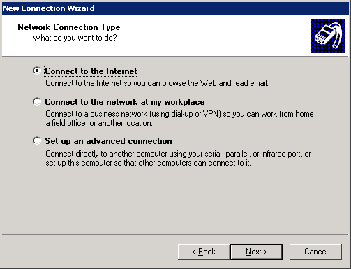
c. On the window that appears, select Connect to the Internet, and click Next, as shown in Figure 4.
Figure 4 Selecting network connection type
d. On the window that appears, select Connect using a broadband connection that requires a user name and password, and click Next, as shown in Figure 5.
Figure 5 Selecting Internet Connection method

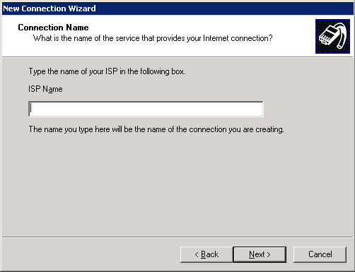
e. On the window that appears, perform either of the following tasks, as shown in Figure 6:
- Enter an ISP name in the ISP Name field, and click Next.
- Click Next directly.
Figure 6 Creating a connection name
f. On the window that appears, select Anyone's use, and click Next, as shown in Figure 7.
Figure 7 Configuring the connection availability

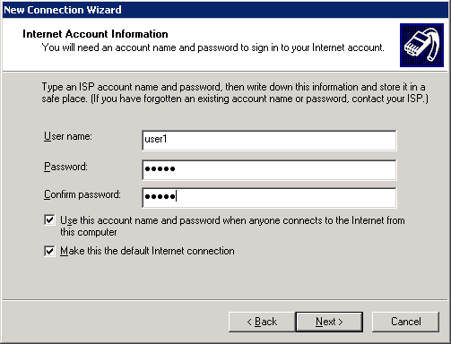
g. On the window that appears, perform the following tasks, as shown in Figure 8:
- Enter user1 in the User name field.
- Enter pass1 in the Password and the Confirm password fields.
- Click Next.
Figure 8 Configuring Internet account information
h. On the window that appears, click Finish.
The connection dialog box appears, as shown in Figure 9.
Figure 9 The connection dialog box

i. On the dialog box, click Connect.
j. Return to the Network Connections page.
You can view a new broadband connection.
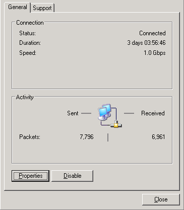
k. Double click the connection.
The broadband connection status window appears, as shown in Figure 10, which indicates that the connection has been established successfully.
Figure 10 The broadband connection status window
2. Display the relay entry on the relay agent on Device A.
[DeviceA] display dhcp relay client-information
Total number of client-information items: 1
Total number of dynamic items: 1
Total number of temporary items: 0
IP address MAC address Type Interface VPN name
2.2.2.1 3408-0499-b48c Dynamic VA0 N/A
3. Display binding information about the assigned DHCP address on Device B.
[DeviceB] display dhcp server ip-in-use
IP address Client identifier/ Lease expiration Type
Hardware address
2.2.2.1 0033-3430-382e-3034- Jul 24 16:28:57 2017 Auto(C)
3939-2e62-3438-632d-
5641-30
Configuration files
· Device A:
#
dhcp enable
dhcp relay client-information record
#
dhcp server ip-pool pool1
gateway-list 2.2.2.10 2.2.2.20 export-route
remote-server 3.1.1.1
#
interface Virtual-Template10
ppp authentication-mode chap domain system
ip address 1.1.1.1 255.255.255.0
#
interface GigabitEthernet2/1/0
port link-mode route
pppoe-server bind virtual-template 10
#
interface GigabitEthernet2/1/1
port link-mode route
ip address 3.1.1.2 255.255.255.0
#
domain system
authorization-attribute ip-pool pool1
authentication ppp local
#
local-user user1 class network
password cipher $c$3$rgL97ckhgtCEhbMs1yy7lxMp2yVuIOk8
service-type ppp
authorization-attribute user-role network-operator
· Device B:
#
dhcp enable
#
dhcp server ip-pool pool1
#
dhcp server ip-pool pool1
gateway-list 2.2.2.1
network 2.2.2.0 mask 255.255.255.0
#
interface GigabitEthernet2/1/1
port link-mode route
ip address 3.1.1.1 255.255.255.0
#
ip route-static 2.2.2.0 24 3.1.1.2
Related documentation
· H3C SR6600 SR6600-X Routers Layer 2—WAN Access Command Reference-Release 7607
· H3C SR6600 SR6600-X Routers Layer 2—WAN Access Configuration Guide-Release 7607