- Table of Contents
-
- 06-IP Multicast Configuration Guide
- 00-Preface
- 01-Multicast overview
- 02-IGMP snooping configuration
- 03-PIM snooping configuration
- 04-Multicast VLAN configuration
- 05-Multicast routing and forwarding configuration
- 06-IGMP configuration
- 07-PIM configuration
- 08-MSDP configuration
- 09-Multicast VPN configuration
- 10-MLD snooping configuration
- 11-IPv6 PIM snooping configuration
- 12-IPv6 multicast VLAN configuration
- 13-IPv6 multicast routing and forwarding configuration
- 14-MLD configuration
- 15-IPv6 PIM configuration
- Related Documents
-
| Title | Size | Download |
|---|---|---|
| 08-MSDP configuration | 404.16 KB |
Contents
Configuring basic MSDP features
Configuring an MSDP peering connection
Configuring a description for an MSDP peer
Configuring an MSDP mesh group
Controlling MSDP peering connections
Configuring SA message-related parameters
Enabling multicast data encapsulation in SA messages
Configuring the originating RP of SA messages
Configuring SA request messages
Configuring SA message policies
Configuring the SA cache mechanism
Setting the DSCP value for outgoing MSDP protocol packets
Displaying and maintaining MSDP
PIM-SM inter-domain multicast configuration
Inter-AS multicast configuration by leveraging static RPF peers
SA message filtering configuration
MSDP peers stay in disabled state
No SA entries exist in the router's SA message cache
No exchange of locally registered (S, G) entries between RPs
Configuring MSDP
Overview
Multicast Source Discovery Protocol (MSDP) is an inter-domain multicast solution that addresses the interconnection of PIM-SM domains. It discovers multicast source information in other PIM-SM domains.
In the basic PIM-SM mode, a multicast source registers only with the RP in the local PIM-SM domain, and the multicast source information in each domain is isolated. As a result, both of the following occur:
· The RP obtains the source information only within the local domain.
· A multicast distribution tree is built only within the local domain to deliver multicast data locally.
MSDP enables the RPs of different PIM-SM domains to share their multicast source information. The local RP can then join the SPT rooted at the multicast source across the PIM-SM domains. This allows multicast data to be transmitted among different domains.
With MSDP peer relationships established between appropriate routers on the network, the RPs of different PIM-SM domains are interconnected with one another. These MSDP peers exchange source active (SA) messages, so that the multicast source information is shared among these domains.
MSDP is applicable only if the intra-domain multicast protocol is PIM-SM. MSDP takes effect only for the ASM model.
For more information about the concepts of DR, BSR, C-BSR, RP, C-RP, SPT, and RPT mentioned in this document, see "Configuring PIM."
How MSDP works
MSDP peers
One or more pairs of MSDP peers on the network form an MSDP interconnection map. In the map, the RPs of different PIM-SM domains interconnect in a series. An SA message from an RP is relayed to all other RPs by these MSDP peers.
Figure 1 MSDP peer locations on the network
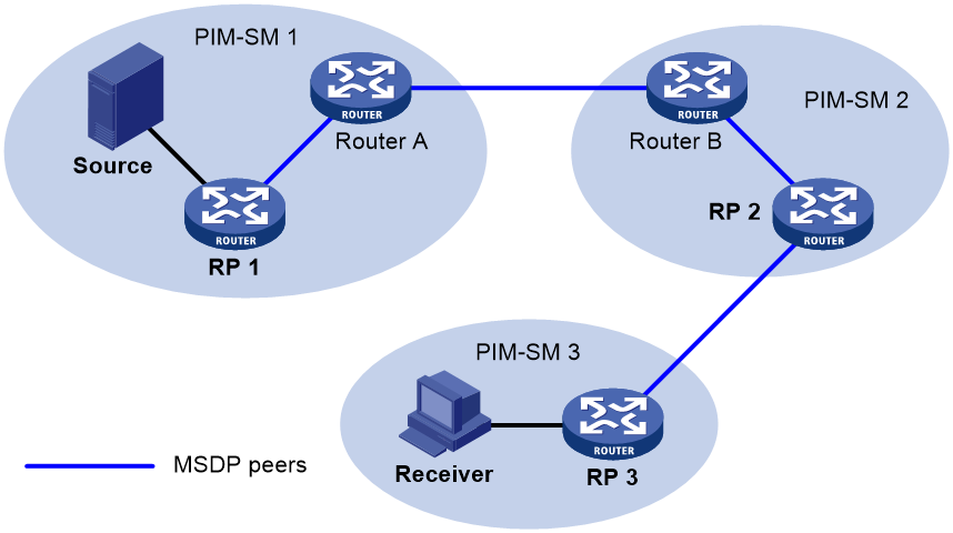
As shown in Figure 1, an MSDP peer can be created on any PIM-SM router. MSDP peers created on PIM-SM routers that assume different roles function differently.
· MSDP peers created on RPs:
¡ Source-side MSDP peer—MSDP peer closest to the multicast source, such as RP 1. The source-side RP creates and sends SA messages to its remote MSDP peer to notify the MSDP peer of the locally registered multicast source information.
A source-side MSDP peer must be created on the source-side RP. Otherwise, it cannot advertise the multicast source information out of the PIM-SM domain.
¡ Receiver-side MSDP peer—MSDP peer closest to the receivers, typically the receiver-side RP, such as RP 3. After receiving an SA message, the receiver-side MSDP peer resolves the multicast source information carried in the message. Then, it joins the SPT rooted at the multicast source across the PIM-SM domains. When multicast data from the multicast source arrives, the receiver-side MSDP peer forwards the data to the receivers along the RPT.
¡ Intermediate MSDP peer—MSDP peer with multiple remote MSDP peers, such as RP 2. An intermediate MSDP peer forwards SA messages received from one remote MSDP peer to other remote MSDP peers. It acts as a relay for forwarding multicast source information.
· MSDP peers created on PIM-SM routers that are not RPs:
Router A and Router B are MSDP peers on multicast routers that are not RPs. Such MSDP peers only forward SA messages.
In a PIM-SM network using the BSR mechanism, the RP is dynamically elected from C-RPs. A PIM-SM network typically has multiple C-RPs to ensure network robustness. Because the RP election result is unpredictable, MSDP peering relationships must be built between all C-RPs to always keep the winning C-RP on the MSDP interconnection map. Losing C-RPs assume the role of common PIM-SM routers on this map.
Inter-domain multicast delivery through MSDP
As shown in Figure 2, an active source (Source) exists in the domain PIM-SM 1, and RP 1 has learned the existence of Source through multicast source registration. RPs in PIM-SM 2 and PIM-SM 3 also seek the location of Source so that multicast traffic from Source can be sent to their receivers. MSDP peering relationships must be established between RP 1 and RP 3 and between RP 3 and RP 2.
Figure 2 Inter-domain multicast delivery through MSDP
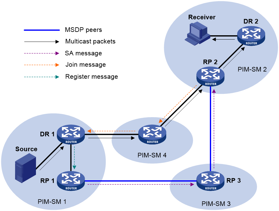
The process of implementing PIM-SM inter-domain multicast delivery by leveraging MSDP peers is as follows:
1. When the multicast source in PIM-SM 1 sends the first multicast packet to multicast group G, DR 1 encapsulates the data within a register message. It sends the register message to RP 1, and RP 1 obtains information about the multicast source.
2. As the source-side RP, RP 1 creates SA messages and periodically sends them to its MSDP peer.
An SA message contains the address of the multicast source (S), the multicast group address (G), and the address of the RP that has created this SA message (RP 1, in this example).
3. On MSDP peers, each SA message undergoes an RPF check and multicast policy-based filtering. Only SA messages that have arrived along the correct path and passed the filtering are received and forwarded. This avoids delivery loops of SA messages. In addition, you can configure MSDP peers into an MSDP mesh group to avoid SA message flooding between MSDP peers.
|
|
NOTE: An MSDP mesh group refers to a group of MSDP peers that establish MSDP peering relationships with each other and share the same group name. |
4. SA messages are forwarded from one MSDP peer to another. Finally, information about the multicast source traverses all PIM-SM domains with MSDP peers (PIM-SM 2 and PIM-SM 3, in this example).
5. After receiving the SA message that RP 1 created, RP 2 in PIM-SM 2 examines whether any receivers for the multicast group exist in the domain.
¡ If a receiver exists in the domain, the RPT for the multicast group G is maintained between RP 2 and the receivers. RP 2 creates an (S, G) entry and sends an (S, G) join message. The join message travels hop by hop toward the multicast source, and the SPT is established across the PIM-SM domains.
The subsequent multicast data flows to RP 2 along the SPT, and from RP 2 to the receiver-side DR along the RPT. After receiving the multicast data, the receiver-side DR determines whether to initiate an RPT-to-SPT switchover process based on its configuration.
¡ If no receivers exist in the domain, RP 2 neither creates an (S, G) entry nor sends a join message toward the multicast source.
In inter-domain multicasting using MSDP, once an RP gets information about a multicast source in another PIM-SM domain, it no longer relies on RPs in other PIM-SM domains. The receivers can override the RPs in other domains and directly join the multicast SPT rooted at the source.
Anycast RP through MSDP
PIM-SM requires only one active RP to serve each multicast group. If the active RP fails, the multicast traffic might be interrupted. The Anycast RP mechanism enables redundancy backup between two or more RPs by configuring multiple RPs with the same IP address for one multicast group. A multicast source registers with the closest RP or a receiver joins the closest RP to implement source information synchronization.
Anycast RP has the following benefits:
· Optimal RP path—A multicast source registers with the closest RP to build an optimal SPT. A receiver joins the closest RP to build an optimal RPT.
· Redundancy backup among RPs—When an RP fails, the RP-related sources and receiver-side DRs will register with or join their closest available RPs. This achieves redundancy backup among RPs.
Anycast RP is implemented by using either of the following methods:
· Anycast RP through PIM-SM—In this method, you can configure multiple RPs for one multicast group and add them to an Anycast RP set. For more information about Anycast RP through PIM-SM, see "Configuring PIM."
· Anycast RP through MSDP—In this method, you can configure multiple RPs with the same IP address for one multicast group and configure MSDP peering relationships between the RPs.
As shown in Figure 3, within a PIM-SM domain, a multicast source sends multicast data to multicast group G, and the receiver joins the multicast group.
To implement Anycast RP through MSDP:
a. Assign the same IP address (known as Anycast RP address, typically a private address) to an interface on Router A and Router B.
- An Anycast RP address is usually assigned to a logical interface, such as a loopback interface.
- Make sure the Anycast RP address is a host address (with the subnet mask 255.255.255.255).
b. Configure the interfaces as C-RPs.
c. Establish an MSDP peering relationship between Router A and Router B.
An MSDP peer address must be different from the Anycast RP address.
Figure 3 Anycast RP through MSDP
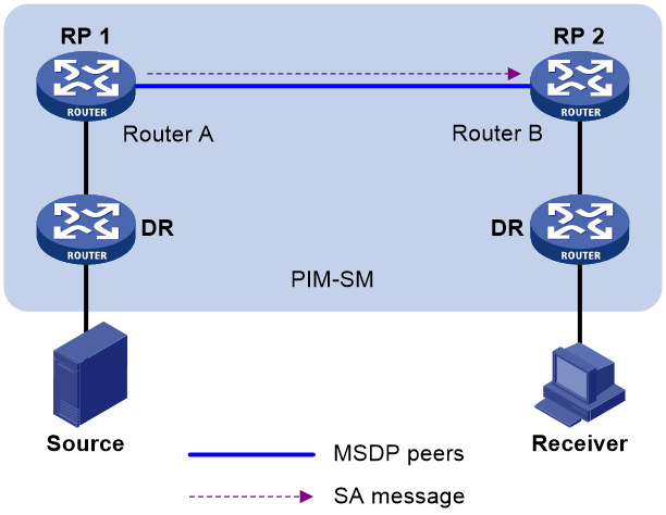
The following describes how Anycast RP through MSDP is implemented:
a. After receiving the multicast data from Source, the source-side DR registers with the closest RP (RP 1 in this example).
b. After receiving the IGMP report message from the receiver, the receiver-side DR sends a join message toward the closest RP (RP 2 in this example). An RPT rooted at this RP is established.
c. The RPs share the registered multicast source information through SA messages. After obtaining the multicast source information, RP 2 sends an (S, G) source-specific join message toward the source to create an SPT.
d. When the multicast data reaches RP 2 along the SPT, the RP forwards the data along the RPT to the receiver. After receiving the multicast data, the receiver-side DR determines whether to initiate an RPT-to-SPT switchover process based on its configuration.
MSDP peer-RPF forwarding
The MSDP peer-RPF check is used for forwarding SA messages on a network that runs MSDP. If the peer-RPF check succeeds, the SA message is accepted and forwarded. Otherwise, the SA message is discarded.
As shown in Figure 4:
· There are five ASs on the network. IGP runs within each AS, and BGP or MBGP runs between these ASs.
· Each AS contains a minimum of one PIM-SM domain, and each PIM-SM domain contains a minimum of one RP.
· MSDP peering relationship has been established among these RPs.
RP 3, RP 4, and RP 5 are in the same MSDP mesh group.
RP 6 is configured as the static RPF peer of RP 7.
Figure 4 MSDP peer-RPF forwarding
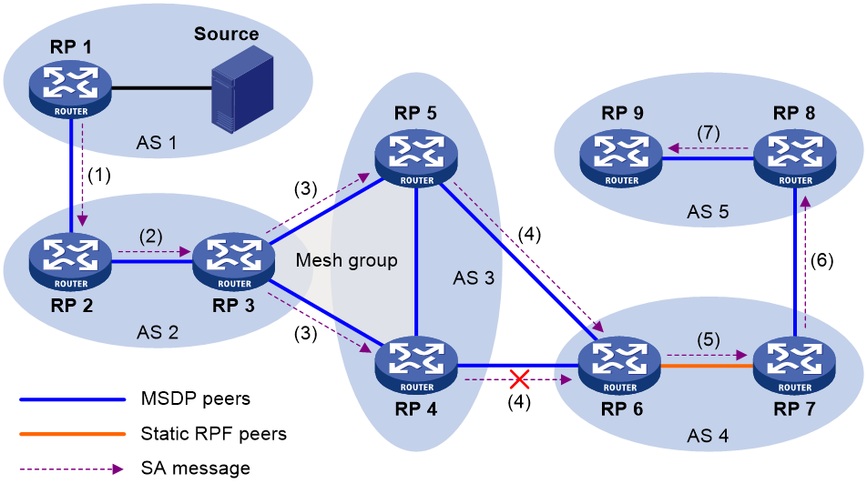
The process of peer-RPF forwarding is as follows:
1. RP 1 creates an SA message and forwards it to its peer RP 2.
2. RP 2 determines that RP 1 is the RP that creates the SA message because the RP address in the SA message is the same as that of RP 1. Then, RP 2 accepts and forwards the SA message.
3. RP 3 accepts and forwards the SA message, because RP 2 and RP 3 reside in the same AS and RP 2 is the next hop of RP 3 to RP 1.
4. RP 4 and RP 5 accept the SA message, because RP 3 is in the same mesh group with them. Then, RP 4 and RP 5 forward the SA message to their peer RP 6 rather than other members of the mesh group.
5. RP 4 and RP 5 reside in the closest AS in the route to RP 1. However, RP 6 accepts and forwards only the SA message from RP 5, because the IP address of RP 5 is higher than that of RP 4.
6. RP 7 accepts and forwards the SA message, because RP 6 is its static RPF peer.
7. RP 8 accepts and forwards the SA message, because RP 7 is the EBGP or MBGP next hop of the peer-RPF route to RP 1.
8. RP 9 accepts the SA message, because RP 8 is the only RP of RP 9.
MSDP support for VPNs
Interfaces on the multicast routers in a VPN can set up MSDP peering relationships with each other. With the SA messages exchanged between MSDP peers, the multi-instance VPN implements the forwarding of multicast data across different PIM-SM domains.
To support MSDP for VPNs, a multicast router that runs MSDP maintains an independent set of MSDP mechanism for each VPN that it supports. These mechanisms include SA message cache, peering connection, timers, sending cache, and cache for exchanging PIM messages.
One VPN is isolated from another, and MSDP and PIM-SM messages can be exchanged only within the same VPN.
Protocols and standards
· RFC 3618, Multicast Source Discovery Protocol (MSDP)
· RFC 3446, Anycast Rendezvous Point (RP) mechanism using Protocol Independent Multicast (PIM) and Multicast Source Discovery Protocol (MSDP)
MSDP configuration task list
|
Tasks at a glance |
|
Configuring basic MSDP features: · (Required.) Enabling MSDP · (Required.) Specifying an MSDP peer · (Optional.) Configuring a static RPF peer |
|
(Optional.) Configuring an MSDP peering connection: · Configuring a description for an MSDP peer |
|
(Optional.) Configuring SA message-related parameters: · Enabling multicast data encapsulation in SA messages · Configuring the originating RP of SA messages · Configuring SA request messages |
|
(Optional.) Enabling MSDP NSR |
|
(Optional.) Setting the DSCP value for outgoing MSDP protocol packets |
Configuring basic MSDP features
All the configuration tasks in this section should be performed on RPs in PIM-SM domains, and each of these RPs acts as an MSDP peer.
Configuration prerequisites
Before you configure basic MSDP features, complete the following tasks:
· Configure a unicast routing protocol so that all devices in the domain can interoperate at the network layer.
· Configure PIM-SM to enable intra-domain multicast.
Enabling MSDP
|
Step |
Command |
Remarks |
|
1. Enter system view. |
system-view |
N/A |
|
2. Enable IP multicast routing and enter MRIB view. |
multicast routing [ vpn-instance vpn-instance-name ] |
By default, IP multicast routing is disabled. |
|
3. Return to system view. |
quit |
N/A |
|
4. Enable MSDP and enter MSDP view. |
msdp [ vpn-instance vpn-instance-name ] |
By default, MSDP is disabled. |
Specifying an MSDP peer
An MSDP peering relationship is identified by an address pair (the addresses of the local MSDP peer and the remote MSDP peer). To create an MSDP peering connection, you must perform the following operation on both devices that are a pair of MSDP peers.
If an MSDP peer and a BGP or MBGP peer share the same interface, specify the MSDP peer and the BGP or MBGP peer by using the same IP address.
To specify an MSDP peer:
|
Step |
Command |
Remarks |
|
1. Enter system view. |
system-view |
N/A |
|
2. Enter MSDP view. |
msdp [ vpn-instance vpn-instance-name ] |
N/A |
|
3. Specify an MSDP peer. |
peer peer-address connect-interface interface-type interface-number |
By default, no MSDP peers exist. |
Configuring a static RPF peer
This feature prevents SA messages forwarded by the static RPF peer from undertaking the RPF check. This simplifies the RPF check mechanism for SA messages.
You can configure an RP policy for the static RPF peer to filter SA messages based on the used IPv4 prefix list that specifies the RP addresses.
If only one MSDP peer is configured on a router, this MSDP peer is considered to be a static RPF peer.
To configure a static RPF peer:
|
Step |
Command |
Remarks |
|
1. Enter system view. |
system-view |
N/A |
|
2. Enter MSDP view. |
msdp [ vpn-instance vpn-instance-name ] |
N/A |
|
3. Configure a static RPF peer. |
static-rpf-peer peer-address [ rp-policy ip-prefix-name ] |
By default, no static RPF peers exist. |
Configuring an MSDP peering connection
This section describes how to configure an MSDP peering connection.
Configuration prerequisites
Before you configure an MSDP peering connection, complete the following tasks:
· Configure a unicast routing protocol so that all devices in the domain can interoperate at the network layer.
· Configure basic MSDP features.
Configuring a description for an MSDP peer
This feature helps administrators easily distinguish an MSDP peer from other MSDP peers.
To configure a description for an MSDP peer:
|
Step |
Command |
Remarks |
|
1. Enter system view. |
system-view |
N/A |
|
2. Enter MSDP view. |
msdp [ vpn-instance vpn-instance-name ] |
N/A |
|
3. Configure a description for an MSDP peer. |
peer peer-address description text |
By default, no description for an MSDP peer exists. |
Configuring an MSDP mesh group
This feature avoids SA message flooding among MSDP peers within an AS. It also simplifies the RPF check mechanism because you do not need to run BGP or MBGP between these MSDP peers.
When receiving an SA message from outside the mesh group, a member MSDP peer performs the RPF check on the SA message. If the SA message passes the RPF check, the member MSDP peer floods the message to the other members in the mesh group. When receiving an SA message from another member, the MSDP peer neither performs an RPF check on the message nor forwards the message to the other members.
To organize multiple MSDP peers in a mesh group, assign the same mesh group name to these MSDP peers. Before doing this, make sure the routers are interconnected with one another.
To configure an MSDP mesh group:
|
Step |
Command |
Remarks |
|
1. Enter system view. |
system-view |
N/A |
|
2. Enter MSDP view. |
msdp [ vpn-instance vpn-instance-name ] |
N/A |
|
3. Configure an MSDP mesh group. |
peer peer-address mesh-group name |
By default, an MSDP peer does not belong to any mesh group. If you assign an MSDP peer to multiple mesh groups, the most recent configuration takes effect. |
Controlling MSDP peering connections
MSDP peers are interconnected over TCP (port number 639). You can tear down or re-establish MSDP peering connections to control SA message exchange between the MSDP peers. When the connection between two MSDP peers is torn down, SA messages are no longer delivered between them. No attempt is made to re-establish the connection. The configuration information for the peer remains unchanged.
MSDP peers periodically send keepalive messages to each other to keep a session alive. When a session is established, an MSDP peer sends a keepalive message to its peer and starts a keepalive timer and a peer hold timer. When the keepalive timer expires, the MSDP peer sends a new keepalive message. If the MSDP peer receives an MSDP message from its peer before the peer hold timer expires, it resets the peer hold timer. Otherwise, the MSDP peer tears down the session.
A TCP connection is required when one of the following conditions exists:
· A new MSDP peer is created.
· A previously deactivated MSDP peering connection is reactivated.
· A previously failed MSDP peer attempts to resume operation.
You can change the MSDP connection retry interval to adjust the interval between MSDP peering connection attempts.
To enhance MSDP security, enable MD5 authentication for both MSDP peers to establish a TCP connection. If the MD5 authentication fails, the TCP connection cannot be established.
|
|
IMPORTANT: The MSDP peers involved in MD5 authentication must be configured with the same authentication method and key. Otherwise, the authentication fails and the TCP connection cannot be established. |
To control MSDP peering connections:
|
Step |
Command |
Remarks |
|
1. Enter system view. |
system-view |
N/A |
|
2. Enter MSDP view. |
msdp [ vpn-instance vpn-instance-name ] |
N/A |
|
3. Tear down an MSDP peering connection. |
shutdown peer-address |
By default, an MSDP peering connection is active. |
|
4. Set the keepalive timer and peer hold timer for MSDP sessions. |
timer keepalive keepalive holdtime |
By default, the keepalive timer and peer hold timer are 60 seconds and 75 seconds, respectively. This command immediately takes effect on an established session. |
|
5. Configure the MSDP connection retry interval. |
timer retry interval |
The default setting is 30 seconds. |
|
6. Configure the device to perform MD5 authentication when establishing a TCP connection with an MSDP peer. |
peer peer-address password { cipher | simple } password |
By default, the device does not perform MD5 authentication when establishing a TCP connection with an MSDP peer. |
Configuring SA message-related parameters
This section describes how to configure SA message-related parameters.
Configuration prerequisites
Before you configure SA message delivery, complete the following tasks:
· Configure a unicast routing protocol so that all devices in the domain can interoperate at the network layer.
· Configure basic MSDP features.
Enabling multicast data encapsulation in SA messages
Some multicast sources send multicast data at an interval longer than the aging time of (S, G) entries. In this case, the source-side DR must encapsulate multicast data packet-by-packet in register messages and send them to the source-side RP. The source-side RP transmits the (S, G) information to the remote RP through SA messages. Then, the remote RP sends join messages to the source-side DR and builds an SPT. Because the (S, G) entries have timed out, remote receivers can never receive the multicast data from the multicast source.
To avoid this problem, you can enable the source-side RP to encapsulate multicast data in SA messages. As a result, the source-side RP can forward the multicast data in SA messages to its remote MSDP peers. After receiving the SA messages, the remote RP decapsulates the SA messages and forwards the multicast data to the receivers in the local domain along the RPT.
To enable multicast data encapsulation in SA messages:
|
Step |
Command |
Remarks |
|
1. Enter system view. |
system-view |
N/A |
|
2. Enter MSDP view. |
msdp [ vpn-instance vpn-instance-name ] |
N/A |
|
3. Enable multicast data encapsulation in SA messages. |
encap-data-enable |
By default, an SA message contains only (S, G) entries, but not the multicast data. |
Configuring the originating RP of SA messages
This feature enables an interface to originate SA messages and to use its IP address as the RP address in SA messages. It is typically used in the Anycast-RP application.
By default, the RP address in SA messages originated by a member Anycast-RP is the Anycast-RP address. The SA messages will fail the RPF check on the other members because the RP address in SA messages is the same as the local RP address. In this case, source information cannot be exchanged within the Anycast-RP. To solve the problem, you must specify an interface other than the interface where the member Anycast-RP resides as the originating RP of SA messages.
To configure the originating RP of SA messages:
|
Step |
Command |
Remarks |
|
1. Enter system view. |
system-view |
N/A |
|
2. Enter MSDP view. |
msdp [ vpn-instance vpn-instance-name ] |
N/A |
|
3. Configure an interface as the originating RP of SA messages. |
originating-rp interface-type interface-number |
By default, SA messages are originated by the actual RPs. |
Configuring SA request messages
An SA request policy enables the device to filter SA request messages from an MSDP peer by using an ACL that specifies the multicast groups.
|
|
IMPORTANT: Before you enable the router to send SA requests, make sure you disable the SA message cache mechanism. |
To configure SA request messages:
|
Step |
Command |
Remarks |
|
1. Enter system view. |
system-view |
N/A |
|
2. Enter MSDP view. |
msdp [ vpn-instance vpn-instance-name ] |
N/A |
|
3. Enable the device to send SA request messages to an MSDP peer. |
peer peer-address request-sa-enable |
By default, after receiving a new join message, a device does not send an SA request message to any MSDP peer. Instead, it waits for the next SA message from its MSDP peer. |
|
4. Configure an SA request policy for an MSDP peer. |
peer peer-address sa-request-policy [ acl ipv4-acl-number ] |
By default, no SA request policy exists, and all SA request from an MSDP peer are permitted. |
Configuring SA message policies
To control the propagation of multicast source information, you can configure the following policies:
· SA creation policy—Limits the multicast source information advertised in SA messages. This policy enables the router to advertise (S, G) entries based on the used ACL that specifies the multicast sources and groups.
· SA incoming or outgoing policy—Limits the receipt or forwarding of SA messages. This policy enables the router to receive or forward SA messages based on the used ACL that specifies the multicast sources and groups.
By default, multicast data packets are encapsulated in SA messages and forwarded to MSDP peers only if the TTL values in the packets are larger than zero. You can set the lower TTL threshold for multicast data packets encapsulated in SA messages that are sent to an MSDP peer. Then, only multicast data packets whose TTL values are larger than or equal to the configured value are encapsulated in SA messages. Only SA messages whose TTL values are larger than or equal to the configured value are forwarded to the specified MSDP peer. This controls the multicast data packet encapsulation and limits the propagation range of the SA messages.
To configure SA message policies:
|
Step |
Command |
Remarks |
|
1. Enter system view. |
system-view |
N/A |
|
2. Enter MSDP view. |
msdp [ vpn-instance vpn-instance-name ] |
N/A |
|
3. Configure an SA creation policy. |
import-source [ acl ipv4-acl-number ] |
By default, no SA creation policies exist. |
|
4. Configure an SA incoming or outgoing policy. |
peer peer-address sa-policy { export | import } [ acl ipv4-acl-number ] |
By default, no SA incoming or outgoing policy exists. |
|
5. Set the lower TTL threshold for multicast data packets encapsulated in SA messages. |
peer peer-address minimum-ttl ttl-value |
The default setting is 0. |
Configuring the SA cache mechanism
The SA cache mechanism enables the router to locally cache (S, G) entries contained in SA messages. It reduces the time for obtaining multicast source information, but increases memory occupation.
With the SA cache mechanism enabled, when the router receives a new (*, G) join message, it searches its SA message cache first.
· If no matching (S, G) entry is found, the router waits for the SA message that its MSDP peer sends in the next cycle.
· If a matching (S, G) entry is found in the cache, the router joins the SPT rooted at S.
To protect the router against DoS attacks, you can set a limit on the number of (S, G) entries in the SA cache from an MSDP peer.
To configure the SA cache mechanism:
|
Step |
Command |
Remarks |
|
1. Enter system view. |
system-view |
N/A |
|
2. Enter MSDP view. |
msdp [ vpn-instance vpn-instance-name ] |
N/A |
|
3. Enable the SA cache mechanism. |
cache-sa-enable |
By default, the SA message cache mechanism is enabled. The device caches the (S, G) entries contained in the received SA messages. |
|
4. Set the maximum number of (S, G) entries in the SA cache from an MSDP peer. |
peer peer-address sa-cache-maximum sa-limit |
The default setting is 4294967295. |
Enabling MSDP NSR
This command enables MSDP to back up protocol state information and data, such as MSDP peer and remote multicast source information, from the active process to standby processes. A standby process seamlessly takes over when the active process fails. Use this feature to avoid forwarding interruption for MSDP when an active/standby switchover occurs.
To enable MSDP NSR:
|
Step |
Command |
Remarks |
|
1. Enter system view. |
system-view |
N/A |
|
2. Enable MSDP NSR. |
msdp non-stop-routing |
By default, MSDP NSR is disabled. |
Setting the DSCP value for outgoing MSDP protocol packets
The DSCP value determines the packet transmission priority. A greater DSCP value represents a higher priority.
To set the DSCP value for outgoing MSDP protocol packets:
|
Step |
Command |
Remarks |
|
1. Enter system view. |
system-view |
N/A |
|
2. Enter MSDP view. |
msdp [ vpn-instance vpn-instance-name ] |
N/A |
|
3. Set the DSCP value for outgoing MSDP protocol packets. |
dscp dscp-value |
The default setting is 48. |
Displaying and maintaining MSDP
Execute display commands in any view and reset commands in user view.
|
Task |
Command |
|
Display brief information about MSDP peers. |
display msdp [ vpn-instance vpn-instance-name ] brief [ state { connect | disabled | established | listen | shutdown } ] |
|
Display MSDP NSR status information. |
display msdp non-stop-routing status |
|
Display detailed status of MSDP peers. |
display msdp [ vpn-instance vpn-instance-name ] peer-status [ peer-address ] |
|
Display (S, G) entries in the SA cache. |
display msdp [ vpn-instance vpn-instance-name ] sa-cache [ group-address | source-address | as-number ] * |
|
Display the number of (S, G) entries in the SA cache. |
display msdp [ vpn-instance vpn-instance-name ] sa-count [ as-number ] |
|
Reset the TCP connection with an MSDP peer and clear statistics for the MSDP peer. |
reset msdp [ vpn-instance vpn-instance-name ] peer [ peer-address ] |
|
Delete (S, G) entries in the SA cache. |
reset msdp [ vpn-instance vpn-instance-name ] sa-cache [ group-address ] |
|
Clear statistics for an MSDP peer without resetting the TCP connection with the MSDP peer. |
reset msdp [ vpn-instance vpn-instance-name ] statistics [ peer-address ] |
MSDP configuration examples
This section provides examples of configuring MSDP on switches.
PIM-SM inter-domain multicast configuration
Network requirements
As shown in Figure 5:
· OSPF runs within AS 100 and AS 200 and BGP runs between them.
· Each PIM-SM domain has a minimum of one multicast source or receiver.
Set up MSDP peering relationships between the RPs in the PIM-SM domains to share multicast source information among the PIM-SM domains.
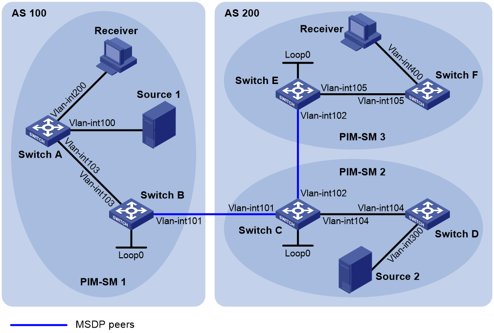
Table 1 Interface and IP address assignment
|
Interface |
IP address |
Device |
Interface |
IP address |
|
|
Switch A |
Vlan-int103 |
10.110.1.2/24 |
Switch D |
Vlan-int104 |
10.110.4.2/24 |
|
Switch A |
Vlan-int100 |
10.110.2.1/24 |
Switch D |
Vlan-int300 |
10.110.5.1/24 |
|
Switch A |
Vlan-int200 |
10.110.3.1/24 |
Switch E |
Vlan-int105 |
10.110.6.1/24 |
|
Switch B |
Vlan-int103 |
10.110.1.1/24 |
Switch E |
Vlan-int102 |
192.168.3.2/24 |
|
Switch B |
Vlan-int101 |
192.168.1.1/24 |
Switch E |
Loop0 |
3.3.3.3/32 |
|
Switch B |
Loop0 |
1.1.1.1/32 |
Switch F |
Vlan-int105 |
10.110.6.2/24 |
|
Switch C |
Vlan-int104 |
10.110.4.1/24 |
Switch F |
Vlan-int400 |
10.110.7.1/24 |
|
Switch C |
Vlan-int102 |
192.168.3.1/24 |
Source 1 |
— |
10.110.2.100/24 |
|
Switch C |
Vlan-int101 |
192.168.1.2/24 |
Source 2 |
— |
10.110.5.100/24 |
|
Switch C |
Loop0 |
2.2.2.2/32 |
Switch D |
Vlan-int104 |
10.110.4.2/24 |
Configuration procedure
1. Assign an IP address and subnet mask to each interface, as shown in Figure 5. (Details not shown.)
2. Configure OSPF on the switches in the ASs. (Details not shown.)
3. Enable IP multicast routing and PIM-SM, and configure PIM-SM domain borders:
# On Switch A, enable IP multicast routing.
<SwitchA> system-view
[SwitchA] multicast routing
[SwitchA-mrib] quit
# Enable PIM-SM on VLAN-interface 103 and VLAN-interface 100.
[SwitchA] interface vlan-interface 103
[SwitchA-Vlan-interface103] pim sm
[SwitchA-Vlan-interface103] quit
[SwitchA] interface vlan-interface 100
[SwitchA-Vlan-interface100] pim sm
[SwitchA-Vlan-interface100] quit
# Enable IGMP on the receiver-side interface (VLAN-interface 200).
[SwitchA] interface vlan-interface 200
[SwitchA-Vlan-interface200] igmp enable
[SwitchA-Vlan-interface200] quit
# Enable IP multicast routing and PIM-SM on Switch B, Switch C, Switch D, Switch E, and Switch F in the same way Switch A is configured. (Details not shown.)
# Configure a PIM domain border on Switch B.
[SwitchB] interface vlan-interface 101
[SwitchB-Vlan-interface101] pim bsr-boundary
[SwitchB-Vlan-interface101] quit
# Configure a PIM domain border on Switch C and Switch E in the same way Switch B is configured. (Details not shown.)
4. Configure C-BSRs and C-RPs:
# Configure Loopback 0 as a C-BSR and a C-RP on Switch B.
[SwitchB] pim
[SwitchB-pim] c-bsr 1.1.1.1
[SwitchB-pim] c-rp 1.1.1.1
[SwitchB-pim] quit
# Configure C-BSRs and C-RPs on Switch C and Switch E in the same way Switch B is configured. (Details not shown.)
5. Configure BGP for mutual route redistribution between BGP and OSPF:
# On Switch B, configure an EBGP peer, and redistribute OSPF routes.
[SwitchB] bgp 100
[SwitchB-bgp] router-id 1.1.1.1
[SwitchB-bgp] peer 192.168.1.2 as-number 200
[SwitchB-bgp] address-family ipv4 unicast
[SwitchB-bgp-ipv4] import-route ospf 1
[SwitchB-bgp-ipv4] peer 192.168.1.2 enable
[SwitchB-bgp-ipv4] quit
# On Switch C, configure an EBGP peer, and redistribute OSPF routes.
[SwitchC] bgp 200
[SwitchC-bgp] router-id 2.2.2.2
[SwitchC-bgp] peer 192.168.1.1 as-number 100
[SwitchC-bgp] address-family ipv4 unicast
[SwitchC-bgp-ipv4] import-route ospf 1
[SwitchC-bgp-ipv4] peer 192.168.1.1 enable
[SwitchC-bgp-ipv4] quit
# Redistribute BGP routes into OSPF on Switch B.
[SwitchB] ospf 1
[SwitchB-ospf-1] import-route bgp
[SwitchB-ospf-1] quit
# Redistribute BGP routes into OSPF on Switch C.
[SwitchB] ospf 1
[SwitchB-ospf-1] import-route bgp
[SwitchB-ospf-1] quit
6. Configure MSDP peers:
# Configure an MSDP peer on Switch B.
[SwitchB] msdp
[SwitchB-msdp] peer 192.168.1.2 connect-interface vlan-interface 101
[SwitchB-msdp] quit
# Configure an MSDP peer on Switch C.
[SwitchC] msdp
[SwitchC-msdp] peer 192.168.1.1 connect-interface vlan-interface 101
[SwitchC-msdp] peer 192.168.3.2 connect-interface vlan-interface 102
[SwitchC-msdp] quit
# Configure MSDP peers on Switch E.
[SwitchE] msdp
[SwitchE-msdp] peer 192.168.3.1 connect-interface vlan-interface 102
[SwitchE-msdp] quit
Verifying the configuration
# Display information about BGP peer groups on Switch B.
[SwitchB] display bgp peer ipv4
BGP local router ID: 1.1.1.1
Local AS number: 100
Total number of peers: 1 Peers in established state: 1
Peer AS MsgRcvd MsgSent OutQ PrefRcv Up/Down State
192.168.1.2 200 24 21 0 6 00:20:07 Established
# Display information about BGP peer groups on Switch C.
[SwitchC] display bgp peer ipv4
BGP local router ID: 2.2.2.2
Local AS number: 1
Total number of peers: 1 Peers in established state: 1
Peer AS MsgRcvd MsgSent OutQ PrefRcv Up/Down State
192.168.1.1 100 18 16 0 1 00:20:07 Established
# Display the BGP routing table on Switch C.
[SwitchC] display bgp routing-table ipv4
Total number of routes: 5
BGP local router ID is 2.2.2.2
Status codes: * - valid, > - best, d - dampened, h - history,
s - suppressed, S - stale, i - internal, e - external
Network NextHop MED LocPrf PrefVal Path/Ogn
* > 1.1.1.1/32 192.168.1.1 0 0 100?
* >i 2.2.2.2/32 0.0.0.0 0 0 ?
* > 192.168.1.0 0.0.0.0 0 0 ?
* > 192.168.1.1/32 0.0.0.0 0 0 ?
* > 192.168.1.2/32 0.0.0.0 0 0 ?
# Verify that hosts in PIM-SM 1 and PIM-SM 3 can receive the multicast data from Source 1 in PIM-SM 1 and Source 2 in PIM-SM 2. (Details not shown.)
# Display brief information about MSDP peer groups on Switch B.
[SwitchB] display msdp brief
Configured Established Listen Connect Shutdown Disabled
1 1 0 0 0 0
Peer address State Up/Down time AS SA count Reset count
192.168.1.2 Established 00:12:57 200 13 0
# Display brief information about MSDP peer groups on Switch C.
[SwitchC] display msdp brief
Configured Established Listen Connect Shutdown Disabled
1 1 0 0 0 0
Peer address State Up/Down time AS SA count Reset count
192.168.3.2 Established 01:43:57 ? 8 0
192.168.1.1 Established 01:43:57 ? 13 0
# Display brief information about MSDP peer groups on Switch E.
[SwitchE] display msdp brief
Configured Established Listen Connect Shutdown Disabled
1 1 0 0 0 0
Peer address State Up/Down time AS SA count Reset count
192.168.3.1 Established 01:07:57 200 8 0
# Display detailed MSDP peer information on Switch B.
[SwitchB] display msdp peer-status
MSDP Peer 192.168.1.2; AS 200
Description:
Information about connection status:
State: Established
Up/down time: 00:15:47
Resets: 0
Connection interface: Vlan-interface101 (192.168.1.1)
Received/sent messages: 16/16
Discarded input messages: 0
Discarded output messages: 0
Elapsed time since last connection or counters clear: 00:17:40
Mesh group peer joined: momo
Last disconnect reason: Hold timer expired with truncated message
Truncated packet: 5 bytes in buffer, type: 1, length: 20, without packet time: 75s
Information about (Source, Group)-based SA filtering policy:
Import policy: None
Export policy: None
Information about SA-Requests:
Policy to accept SA-Requests: None
Sending SA-Requests status: Disable
Minimum TTL to forward SA with encapsulated data: 0
SAs learned from this peer: 0, SA cache maximum for the peer: 4294967295
Input queue size: 0, Output queue size: 0
Counters for MSDP messages:
RPF check failure: 0
Incoming/outgoing SA: 0/0
Incoming/outgoing SA-Request: 0/0
Incoming/outgoing SA-Response: 0/0
Incoming/outgoing Keepalive: 867/867
Incoming/outgoing Notification: 0/0
Incoming/outgoing Traceroutes in progress: 0/0
Incoming/outgoing Traceroute reply: 0/0
Incoming/outgoing Unknown: 0/0
Incoming/outgoing data packet: 0/0
Inter-AS multicast configuration by leveraging static RPF peers
Network requirements
As shown in Figure 6:
· The network has two ASs: AS 100 and AS 200. OSPF runs within each AS. BGP runs between the two ASs.
· PIM-SM 1 belongs to AS 100, and PIM-SM 2 and PIM-SM 3 belong to AS 200. Each PIM-SM domain has a minimum of one multicast source or receiver.
Configure inter-AS multicast as follows:
· Configure Loopback 0 as the C-BSR and C-RP of the related PIM-SM domain on Switch A, Switch D and Switch G.
· According to the peer-RPF forwarding rule, the switches accept SA messages that pass the filtering policy from its static RPF peers. To share multicast source information among PIM-SM domains without changing the unicast topology structure, configure MSDP peering relationships for the RPs of the PIM-SM domains and configure the static RPF peering relationships.
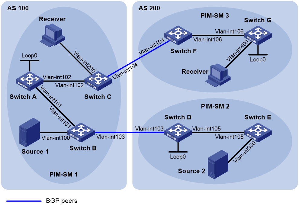
Table 2 Interface and IP address assignment
|
Device |
Interface |
IP address |
Device |
Interface |
IP address |
|
Source 1 |
— |
192.168.1.100/24 |
Switch D |
Vlan-int105 |
10.110.5.1/24 |
|
Source 2 |
— |
192.168.3.100/24 |
Switch D |
Vlan-int103 |
10.110.3.2/24 |
|
Switch A |
Vlan-int101 |
10.110.1.1/24 |
Switch D |
Loop0 |
2.2.2.2/32 |
|
Switch A |
Vlan-int102 |
10.110.2.1/24 |
Switch E |
Vlan-int105 |
10.110.5.2/24 |
|
Switch A |
Loop0 |
1.1.1.1/32 |
Switch E |
Vlan-int300 |
192.168.3.1/24 |
|
Switch B |
Vlan-int101 |
10.110.1.2/24 |
Switch F |
Vlan-int106 |
10.110.6.1/24 |
|
Switch B |
Vlan-int100 |
192.168.1.1/24 |
Switch F |
Vlan-int104 |
10.110.4.2/24 |
|
Switch B |
Vlan-int103 |
10.110.3.1/24 |
Switch G |
Vlan-int106 |
10.110.6.2/24 |
|
Switch C |
Vlan-int102 |
10.110.2.2/24 |
Switch G |
Vlan-int400 |
192.168.4.1/24 |
|
Switch C |
Vlan-int200 |
192.168.2.1/24 |
Switch G |
Loop0 |
3.3.3.3/32 |
|
Switch C |
Vlan-int104 |
10.110.4.1/24 |
Configuration procedure
1. Assign an IP address and subnet mask to each interface, as shown in Table 2. (Details not shown.)
2. Configure OSPF on the switches in the ASs. (Details not shown.)
3. Enable IP multicast routing, PIM-SM, and IGMP, and configure PIM-SM domain borders:
# On Switch C, enable IP multicast routing.
<SwitchC> system-view
[SwitchC] multicast routing
[SwitchC-mrib] quit
# Enable PIM-SM on each interface, and enable IGMP on the receiver-side interface (VLAN-interface 200).
[SwitchC] interface vlan-interface 102
[SwitchC-Vlan-interface102] pim sm
[SwitchC-Vlan-interface102] quit
[SwitchC] interface vlan-interface 200
[SwitchC-Vlan-interface200] igmp enable
[SwitchC-Vlan-interface200] quit
[SwitchC] interface vlan-interface 104
[SwitchC-Vlan-interface104] pim sm
[SwitchC-Vlan-interface104] quit
# Configure Switch A, Switch B, Switch D, Switch E, Switch F, and Switch G in the same way Switch C is configured. (Details not shown.)
# On Switch B, configure the PIM domain borders.
[SwitchB] interface vlan-interface 103
[SwitchB-Vlan-interface103] pim bsr-boundary
[SwitchB-Vlan-interface103] quit
# Configure the PIM domain borders on Switch C, Switch D, and Switch F in the same way Switch B is configured. (Details not shown.)
4. Configure C-BSRs and C-RPs:
# On Switch A, configure Loopback 0 as a C-BSR and a C-RP.
[SwitchA] pim
[SwitchA-pim] c-bsr 1.1.1.1
[SwitchA-pim] c-rp 1.1.1.1
[SwitchA-pim] quit
# Configure C-BSRs and C-RPs on Switch D and Switch G in the same way Switch A is configured. (Details not shown.)
5. Configure BGP, and redistribute BGP routing information into OSPF and OSPF routing information into BGP:
# On Switch B, configure an EBGP peer, and redistribute OSPF routing information.
[SwitchB] bgp 100
[SwitchB-bgp] router-id 1.1.1.2
[SwitchB-bgp] peer 10.110.3.2 as-number 200
[SwitchB-bgp] address-family ipv4 unicast
[SwitchB-bgp-ipv4] peer 10.110.3.2 enable
[SwitchB-bgp-ipv4] import-route ospf 1
[SwitchB-bgp-ipv4]quit
[SwitchB-bgp] quit
# On Switch D, configure an EBGP peer, and redistribute OSPF routing information.
[SwitchD] bgp 200
[SwitchD-bgp] router-id 2.2.2.2
[SwitchD-bgp] peer 10.110.3.1 as-number 100
[SwitchD-bgp] address-family ipv4 unicast
[SwitchD-bgp-ipv4] peer 10.110.3.1 enable
[SwitchD-bgp-ipv4] import-route ospf 1
[SwitchD-bgp-ipv4]quit
[SwitchD-bgp] quit
# On Switch C, configure an EBGP peer, and redistribute OSPF routing information.
[SwitchC] bgp 100
[SwitchC-bgp] router-id 1.1.1.3
[SwitchC-bgp] peer 10.110.4.2 as-number 200
[SwitchC-bgp] address-family ipv4 unicast
[SwitchC-bgp-ipv4] peer 10.110.4.2 enable
[SwitchC-bgp-ipv4] import-route ospf 1
[SwitchC-bgp-ipv4]quit
[SwitchC-bgp] quit
# On Switch F, configure an EBGP peer, and redistribute OSPF routing information.
[SwitchF] bgp 200
[SwitchF-bgp] router-id 3.3.3.1
[SwitchF-bgp] peer 10.110.4.1 as-number 100
[SwitchF-bgp] address-family ipv4 unicast
[SwitchF-bgp-ipv4] peer 10.110.4.1 enable
[SwitchF-bgp-ipv4] import-route ospf 1
[SwitchF-bgp-ipv4]quit
[SwitchF-bgp] quit
# On Switch B, redistribute BGP routing information into OSPF.
[SwitchB] ospf 1
[SwitchB-ospf-1] import-route bgp
[SwitchB-ospf-1] quit
# On Switch D, redistribute BGP routing information into OSPF.
[SwitchD] ospf 1
[SwitchD-ospf-1] import-route bgp
[SwitchD-ospf-1] quit
# On Switch C, redistribute BGP routing information into OSPF.
[SwitchC] ospf 1
[SwitchC-ospf-1] import-route bgp
[SwitchC-ospf-1] quit
# On Switch F, redistribute BGP routing information into OSPF.
[SwitchF] ospf 1
[SwitchF-ospf-1] import-route bgp
[SwitchF-ospf-1] quit
6. Configure MSDP peers and static RPF peers:
# On Switch A, configure Switch D and Switch G as the MSDP peers and static RPF peers.
[SwitchA] ip prefix-list list-dg permit 10.110.0.0 16 greater-equal 16 less-equal 32
[SwitchA] msdp
[SwitchA-msdp] peer 10.110.3.2 connect-interface vlan-interface 101
[SwitchA-msdp] peer 10.110.6.2 connect-interface vlan-interface 102
[SwitchA-msdp] static-rpf-peer 10.110.3.2 rp-policy list-dg
[SwitchA-msdp] static-rpf-peer 10.110.6.2 rp-policy list-dg
[SwitchA-msdp] quit
# On Switch D, configure Switch A as the MSDP peer and static RPF peer.
[SwitchD] ip prefix-list list-a permit 10.110.0.0 16 greater-equal 16 less-equal 32
[SwitchD] msdp
[SwitchD-msdp] peer 10.110.1.1 connect-interface vlan-interface 103
[SwitchD-msdp] static-rpf-peer 10.110.1.1 rp-policy list-a
[SwitchD-msdp] quit
# On Switch G, configure Switch A as the MSDP peer and static RPF peer.
[SwitchG] ip prefix-list list-a permit 10.110.0.0 16 greater-equal 16 less-equal 32
[SwitchG] msdp
[SwitchG-msdp] peer 10.110.2.1 connect-interface vlan-interface 106
[SwitchG-msdp] static-rpf-peer 10.110.2.1 rp-policy list-a
[SwitchG-msdp] quit
Verifying the configuration
# Display the BGP peering relationships on Switch A.
[SwitchA] display bgp peer
No information is output, because no BGP peering relationship has been established between Switch A and Switch D, or between Switch A and Switch G. This means that the unicast topology is not changed.
# Display brief information about MSDP peers on Switch A.
[SwitchA] display msdp brief
Configured Established Listen Connect Shutdown Disabled
2 2 0 0 0 0
Peer address State Up/Down time AS SA count Reset count
10.110.3.2 Established 01:07:08 ? 8 0
10.110.6.2 Established 00:16:39 ? 13 0
# Display brief information about MSDP peers on Switch D.
[SwitchD] display msdp brief
Configured Established Listen Connect Shutdown Disabled
1 1 0 0 0 0
Peer address State Up/Down time AS SA count Reset count
10.110.1.1 Established 01:07:09 ? 8 0
# Display brief information about MSDP peers on Switch G.
[SwitchG] display msdp brief
Configured Established Listen Connect Shutdown Disabled
1 1 0 0 0 0
Peer address State Up/Down time AS SA count Reset count
10.110.2.1 Established 00:16:40 ? 13 0
# Verify that receivers in PIM-SM 1 and PIM-SM 3 can receive the multicast data from Source 1 and Source 2 to a multicast group. (Details not shown.)
Anycast RP configuration
Network requirements
As shown in Figure 7, OSPF runs within the domain to provide unicast routes.
Configure the Anycast RP application so that the receiver-side DRs and the source-side DRs can initiate a join process to their respective RPs that are topologically closest to them.
Configure the router IDs of Switch B and Switch D as 1.1.1.1 and 2.2.2.2, respectively. Set up an MSDP peering relationship between Switch B and Switch D.
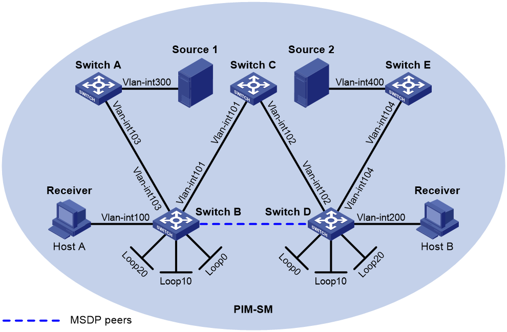
Table 3 Interface and IP address assignment
|
Device |
Interface |
IP address |
Device |
Interface |
IP address |
|
Source 1 |
— |
10.110.5.100/24 |
Switch C |
Vlan-int101 |
192.168.1.2/24 |
|
Source 2 |
— |
10.110.6.100/24 |
Switch C |
Vlan-int102 |
192.168.2.2/24 |
|
Switch A |
Vlan-int300 |
10.110.5.1/24 |
Switch D |
Vlan-int200 |
10.110.3.1/24 |
|
Switch A |
Vlan-int103 |
10.110.2.2/24 |
Switch D |
Vlan-int104 |
10.110.4.1/24 |
|
Switch B |
Vlan-int100 |
10.110.1.1/24 |
Switch D |
Vlan-int102 |
192.168.2.1/24 |
|
Switch B |
Vlan-int103 |
10.110.2.1/24 |
Switch D |
Loop0 |
2.2.2.2/32 |
|
Switch B |
Vlan-int101 |
192.168.1.1/24 |
Switch D |
Loop10 |
4.4.4.4/32 |
|
Switch B |
Loop0 |
1.1.1.1/32 |
Switch D |
Loop20 |
10.1.1.1/32 |
|
Switch B |
Loop10 |
3.3.3.3/32 |
Switch E |
Vlan-int400 |
10.110.6.1/24 |
|
Switch B |
Loop20 |
10.1.1.1/32 |
Switch E |
Vlan-int104 |
10.110.4.2/24 |
Configuration procedure
1. Assign an IP address and subnet mask to each interface, as shown in Figure 7. (Details not shown.)
2. Configure OSPF on the switches. (Details not shown.)
3. Enable IP multicast routing, IGMP, and PIM-SM:
# On Switch B, enable IP multicast routing.
<SwitchB> system-view
[SwitchB] multicast routing
[SwitchB-mrib] quit
# Enable IGMP on the receiver-side interface (VLAN-interface 100).
[SwitchB] interface vlan-interface 100
[SwitchB-Vlan-interface100] igmp enable
[SwitchB-Vlan-interface100] quit
# Enable PIM-SM on the other interfaces.
[SwitchB] interface vlan-interface 103
[SwitchB-Vlan-interface103] pim sm
[SwitchB-Vlan-interface103] quit
[SwitchB] interface Vlan-interface 101
[SwitchB-Vlan-interface101] pim sm
[SwitchB-Vlan-interface101] quit
[SwitchB] interface loopback 0
[SwitchB-LoopBack0] pim sm
[SwitchB-LoopBack0] quit
[SwitchB] interface loopback 10
[SwitchB-LoopBack10] pim sm
[SwitchB-LoopBack10] quit
[SwitchB] interface loopback 20
[SwitchB-LoopBack20] pim sm
[SwitchB-LoopBack20] quit
# Enable IP multicast routing, IGMP, and PIM-SM on Switch A, Switch C, Switch D, and Switch E in the same way Switch B is configured. (Details not shown.)
4. Configure C-BSRs and C-RPs:
# Configure Loopback 10 as a C-BSR and Loopback 20 as a C-RP on Switch B.
[SwitchB] pim
[SwitchB-pim] c-bsr 3.3.3.3
[SwitchB-pim] c-rp 10.1.1.1
[SwitchB-pim] quit
# Configure a C-BSR and a C-RP on Switch D in the same way Switch B is configured. (Details not shown.)
5. Configure MSDP peers:
# Configure an MSDP peer on Loopback 0 of Switch B.
[SwitchB] msdp
[SwitchB-msdp] originating-rp loopback 0
[SwitchB-msdp] peer 2.2.2.2 connect-interface loopback 0
[SwitchB-msdp] quit
# Configure an MSDP peer on Loopback 0 of Switch D.
[SwitchD] msdp
[SwitchD-msdp] originating-rp loopback 0
[SwitchD-msdp] peer 1.1.1.1 connect-interface loopback 0
[SwitchD-msdp] quit
Verifying the configuration
# Display brief information about MSDP peers on Switch B.
[SwitchB] display msdp brief
Configured Established Listen Connect Shutdown Disabled
1 1 0 0 0 0
Peer address State Up/Down time AS SA count Reset count
2.2.2.2 Established 00:10:57 ? 0 0
# Display brief information about MSDP peers on Switch D.
[SwitchD] display msdp brief
Configured Established Listen Connect Shutdown Disabled
1 1 0 0 0 0
Peer address State Up/Down time AS SA count Reset count
1.1.1.1 Established 00:10:57 ? 0 0
# Send an IGMP report from Host A to join multicast group 225.1.1.1. (Details not shown.)
# Send multicast data from Source 1 to multicast group 225.1.1.1. (Details not shown.)
# Display the PIM routing table on Switch D.
[SwitchD] display pim routing-table
No information is output on Switch D.
# Display the PIM routing table on Switch B.
[SwitchB] display pim routing-table
Total 1 (*, G) entry; 1 (S, G) entry
(*, 225.1.1.1)
RP: 10.1.1.1 (local)
Protocol: pim-sm, Flag: WC
UpTime: 00:15:04
Upstream interface: Register
Upstream neighbor: NULL
RPF prime neighbor: NULL
Downstream interface(s) information:
Total number of downstreams: 1
1: Vlan-interface100
Protocol: igmp, UpTime: 00:15:04, Expires: -
(10.110.5.100, 225.1.1.1)
RP: 10.1.1.1 (local)
Protocol: pim-sm, Flag: SPT 2MSDP ACT
UpTime: 00:46:28
Upstream interface: Vlan-interface103
Upstream neighbor: 10.110.2.2
RPF prime neighbor: 10.110.2.2
Downstream interface(s) information:
Total number of downstreams: 1
1: Vlan-interface100
Protocol: pim-sm, UpTime: - , Expires: -
The output shows that Switch B now acts as the RP for Source 1 and Host A.
# Send an IGMP leave message from Host A to leave multicast group 225.1.1.1. (Details not shown.),
# Send an IGMP report from Host B to join multicast group 225.1.1.1. (Details not shown.)
# Send multicast data from Source 2 to multicast group 225.1.1.1. (Details not shown.)
# Display the PIM routing table on Switch B.
[SwitchB] display pim routing-table
No information is output on Switch B.
# Display the PIM routing table on Switch D.
[SwitchD] display pim routing-table
Total 1 (*, G) entry; 1 (S, G) entry
(*, 225.1.1.1)
RP: 10.1.1.1 (local)
Protocol: pim-sm, Flag: WC
UpTime: 00:12:07
Upstream interface: Register
Upstream neighbor: NULL
RPF prime neighbor: NULL
Downstream interface(s) information:
Total number of downstreams: 1
1: Vlan-interface200
Protocol: igmp, UpTime: 00:12:07, Expires: -
(10.110.6.100, 225.1.1.1)
RP: 10.1.1.1 (local)
Protocol: pim-sm, Flag: SPT 2MSDP ACT
UpTime: 00:40:22
Upstream interface: Vlan-interface104
Upstream neighbor: 10.110.4.2
RPF prime neighbor: 10.110.4.2
Downstream interface(s) information:
Total number of downstreams: 1
1: Vlan-interface200
Protocol: pim-sm, UpTime: - , Expires: -
The output shows that Switch D now acts as the RP for Source 2 and Host B.
SA message filtering configuration
Network requirements
As shown in Figure 8:
· OSPF runs within and among the PIM-SM domains to provide unicast routing.
· Set up an MSDP peering relationship between Switch A and Switch C and between Switch C and Switch D.
· Source 1 sends multicast data to multicast groups 225.1.1.0/30 and 226.1.1.0/30, and Source 2 sends multicast data to the multicast group 227.1.1.0/30.
Configure SA message policies so that:
· Host A and Host B receive the multicast data only addressed to multicast groups 225.1.1.0/30 and 226.1.1.0/30.
· Host C receives the multicast data only addressed to multicast groups 226.1.1.0/30 and 227.1.1.0/30.
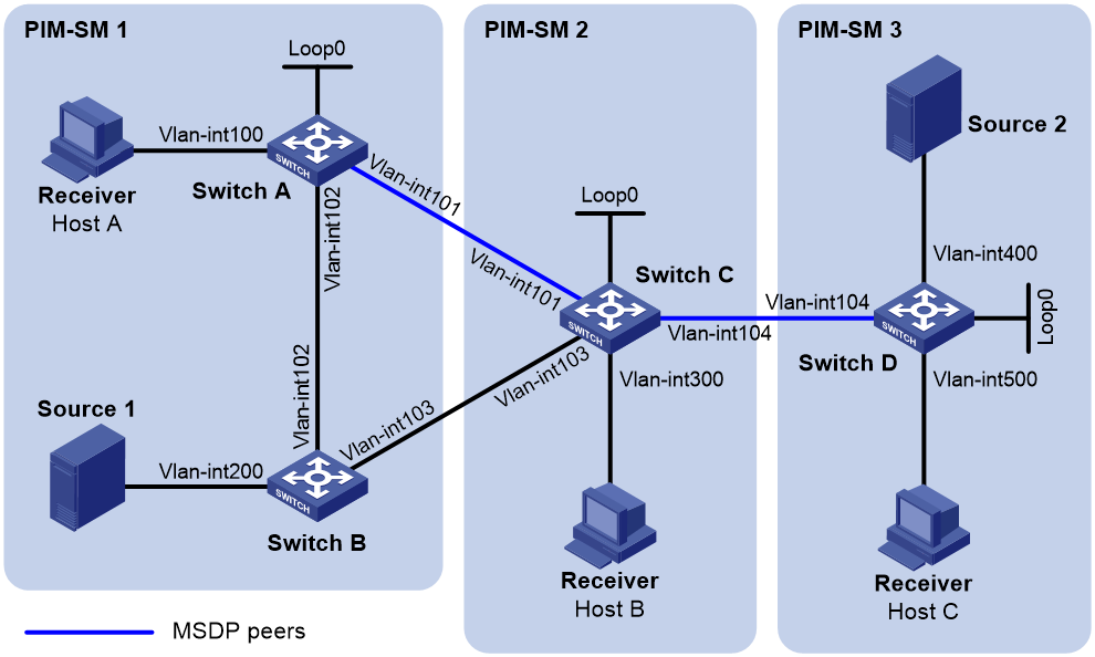
Table 4 Interface and IP address assignment
|
Device |
Interface |
IP address |
Device |
Interface |
IP address |
|
Source 1 |
— |
10.110.3.100/24 |
Switch C |
Vlan-int300 |
10.110.4.1/24 |
|
Source 2 |
— |
10.110.6.100/24 |
Switch C |
Vlan-int104 |
10.110.5.1/24 |
|
Switch A |
Vlan-int100 |
10.110.1.1/24 |
Switch C |
Vlan-int101 |
192.168.1.2/24 |
|
Switch A |
Vlan-int102 |
10.110.2.1/24 |
Switch C |
Vlan-int103 |
192.168.2.2/24 |
|
Switch A |
Vlan-int101 |
192.168.1.1/24 |
Switch C |
Loop0 |
2.2.2.2/32 |
|
Switch A |
Loop0 |
1.1.1.1/32 |
Switch D |
Vlan-int400 |
10.110.6.1/24 |
|
Switch B |
Vlan-int200 |
10.110.3.1/24 |
Switch D |
Vlan-int500 |
10.110.7.1/24 |
|
Switch B |
Vlan-int102 |
10.110.2.2/24 |
Switch D |
Vlan-int104 |
10.110.5.2/24 |
|
Switch B |
Vlan-int103 |
192.168.2.1/24 |
Switch D |
Loop0 |
3.3.3.3/32 |
Configuration procedure
1. Assign an IP address and subnet mask to each interface, as shown in Figure 8. (Details not shown.)
2. Configure OSPF on the switches in the PIM-SM domains. (Details not shown.)
3. Enable IP multicast routing, IGMP, and PIM-SM, and configure PIM domain borders:
# On Switch A, enable IP multicast routing.
<SwitchA> system-view
[SwitchA] multicast routing
[SwitchA-mrib] quit
# Enable IGMP on the receiver-side interface (VLAN-interface 100).
[SwitchA] interface vlan-interface 100
[SwitchA-Vlan-interface100] igmp enable
[SwitchA-Vlan-interface100] quit
# Enable PIM-SM on the other interfaces.
[SwitchA] interface vlan-interface 101
[SwitchA-Vlan-interface101] pim sm
[SwitchA-Vlan-interface101] quit
[SwitchA] interface vlan-interface 102
[SwitchA-Vlan-interface102] pim sm
[SwitchA-Vlan-interface102] quit
[SwitchA] interface loopback 0
[SwitchA-LoopBack0] pim sm
[SwitchA-LoopBack0] quit
# Enable IP multicast routing, IGMP, and PIM-SM on Switch B, Switch C, and Switch D in the same way Switch A is configured. (Details not shown.)
# Configure a PIM domain border on Switch C.
[SwitchC] interface vlan-interface 101
[SwitchC-Vlan-interface101] pim bsr-boundary
[SwitchC-Vlan-interface101] quit
[SwitchC] interface vlan-interface 103
[SwitchC-Vlan-interface103] pim bsr-boundary
[SwitchC-Vlan-interface103] quit
[SwitchC] interface vlan-interface 104
[SwitchC-Vlan-interface104] pim bsr-boundary
[SwitchC-Vlan-interface104] quit
# Configure PIM domain borders on Switch A, Switch B, and Switch D in the same way Switch C is configured. (Details not shown.)
4. Configure C-BSRs and C-RPs:
# Configure Loopback 0 as a C-BSR and a C-RP on Switch A.
[SwitchA] pim
[SwitchA-pim] c-bsr 1.1.1.1
[SwitchA-pim] c-rp 1.1.1.1
[SwitchA-pim] quit
# Configure C-BSRs and C-RPs on Switch C and Switch D in the same way Switch A is configured. (Details not shown.)
5. Configure MSDP peers:
# Configure an MSDP peer on Switch A.
[SwitchA] msdp
[SwitchA-msdp] peer 192.168.1.2 connect-interface vlan-interface 101
[SwitchA-msdp] quit
# Configure MSDP peers on Switch C.
[SwitchC] msdp
[SwitchC-msdp] peer 192.168.1.1 connect-interface vlan-interface 101
[SwitchC-msdp] peer 10.110.5.2 connect-interface vlan-interface 104
[SwitchC-msdp] quit
# Configure an MSDP peer on Switch D.
[SwitchD] msdp
[SwitchD-msdp] peer 10.110.5.1 connect-interface vlan-interface 104
[SwitchD-msdp] quit
6. Configure SA message policies:
# Configure an SA accepting and forwarding policy on Switch C so that Switch C will not forward SA messages for (Source 1, 225.1.1.0/30) to Switch D.
[SwitchC] acl advanced 3001
[SwitchC-acl-ipv4-adv-3001] rule deny ip source 10.110.3.100 0 destination 225.1.1.0 0.0.0.3
[SwitchC-acl-ipv4-adv-3001] rule permit ip source any destination any
[SwitchC-acl-ipv4-adv-3001] quit
[SwitchC] msdp
[SwitchC-msdp] peer 10.110.5.2 sa-policy export acl 3001
[SwitchC-msdp] quit
# Configure an SA creation policy on Switch D so that Switch D will not create SA messages for Source 2.
[SwitchD] acl basic 2001
[SwitchD-acl-ipv4-basic-2001] rule deny source 10.110.6.100 0
[SwitchD-acl-ipv4-basic-2001] quit
[SwitchD] msdp
[SwitchD-msdp] import-source acl 2001
[SwitchD-msdp] quit
Verifying the configuration
# Display the (S, G) entries in the SA message cache on Switch C.
[SwitchC] display msdp sa-cache
MSDP Total Source-Active Cache - 8 entries
Matched 8 entries
Source Group Origin RP Pro AS Uptime Expires
10.110.3.100 225.1.1.0 1.1.1.1 ? ? 02:03:30 00:05:31
10.110.3.100 225.1.1.1 1.1.1.1 ? ? 02:03:30 00:05:31
10.110.3.100 225.1.1.2 1.1.1.1 ? ? 02:03:30 00:05:31
10.110.3.100 225.1.1.3 1.1.1.1 ? ? 02:03:30 00:05:31
10.110.3.100 226.1.1.0 1.1.1.1 ? ? 02:03:30 00:05:31
10.110.3.100 226.1.1.1 1.1.1.1 ? ? 02:03:30 00:05:31
10.110.3.100 226.1.1.2 1.1.1.1 ? ? 02:03:30 00:05:31
10.110.3.100 226.1.1.3 1.1.1.1 ? ? 02:03:30 00:05:31
# Display the (S, G) entries in the SA message cache on Switch D.
[SwitchD] display msdp sa-cache
MSDP Total Source-Active Cache - 4 entries
Matched 4 entries
Source Group Origin RP Pro AS Uptime Expires
10.110.3.100 226.1.1.0 1.1.1.1 ? ? 00:32:53 00:05:07
10.110.3.100 226.1.1.1 1.1.1.1 ? ? 00:32:53 00:05:07
10.110.3.100 226.1.1.2 1.1.1.1 ? ? 00:32:53 00:05:07
10.110.3.100 226.1.1.3 1.1.1.1 ? ? 00:32:53 00:05:07
Troubleshooting MSDP
This section describes common MSDP problems and how to troubleshoot them.
MSDP peers stay in disabled state
Symptom
The configured MSDP peers stay in disabled state.
Analysis
Possible reasons for the problem might include the following:
· A TCP connection-based MSDP peering relationship is established between the local interface address and the MSDP peer.
· The TCP connection setup fails if the local interface address is not consistent with the MSDP peer address configured on the peer router.
· If no route is available between the MSDP peers, the TCP connection setup fails.
Solution
To resolve the problem:
1. Use the display ip routing-table command to verify that the unicast route between the routers is reachable.
2. Verify that a unicast route is available between the two routers that will become MSDP peers to each other.
3. Use the display current-configuration command to verify that the local interface address and the MSDP peer address of the remote router are the same.
4. If the problem persists, contact H3C Support.
No SA entries exist in the router's SA message cache
Symptom
MSDP fails to send (S, G) entries through SA messages.
Analysis
Possible reasons for the problem might include the following:
· The import-source command controls sending (S, G) entries through SA messages to MSDP peers. If this command is executed without the ipv4-acl-number argument, all the (S, G) entries are filtered out, and no (S, G) entries of the local domain are advertised.
· If you do not use the import-source command, the system advertises all the (S, G) entries of the local domain. If MSDP fails to send (S, G) entries through SA messages, verify that the import-source command has been correctly configured.
Solution
To resolve the problem:
1. Use the display ip routing-table command to verify that the unicast route between the routers is reachable.
2. Verify that a unicast route is available between the two routers that will become MSDP peers to each other.
3. Verify the configuration of the import-source command and its ipv4-acl-number argument, and make sure the ACL rule filters appropriate (S, G) entries.
4. If the problem persists, contact H3C Support.
No exchange of locally registered (S, G) entries between RPs
Symptom
RPs fail to exchange their locally registered (S, G) entries with one another in the Anycast RP application.
Analysis
Possible reasons for the problem might include the following:
· In the Anycast RP application, RPs in the same PIM-SM domain are configured to be MSDP peers to achieve redundancy backup among the RPs.
· An MSDP peer address must be different from the Anycast RP address, and the C-BSR and the C-RP must be configured on different devices or interfaces.
· If you configure the originating-rp command, MSDP replaces the RP address in the SA messages with the address of the interface specified in the command.
· When an MSDP peer receives an SA message, it performs an RPF check on the message. If the MSDP peer finds that the remote RP address is the local RP address, it discards the SA message.
Solution
To resolve the problem:
1. Use the display ip routing-table command to verify that the unicast route between the routers is reachable.
2. Verify that a unicast route is available between the two routers that will establish an MSDP peering relationship.
3. Verify the configuration of the originating-rp command. In the Anycast RP application environment, use the originating-rp command to configure the RP address in the SA messages, which must be the local interface address.
4. Verify that the C-BSR address is different from the Anycast RP address.
5. If the problem persists, contact H3C Support.