- Table of Contents
-
- 06-IP Multicast Configuration Guide
- 00-Preface
- 01-Multicast overview
- 02-IGMP snooping configuration
- 03-PIM snooping configuration
- 04-Multicast VLAN configuration
- 05-Multicast routing and forwarding configuration
- 06-IGMP configuration
- 07-PIM configuration
- 08-MSDP configuration
- 09-Multicast VPN configuration
- 10-MLD snooping configuration
- 11-IPv6 PIM snooping configuration
- 12-IPv6 multicast VLAN configuration
- 13-IPv6 multicast routing and forwarding configuration
- 14-MLD configuration
- 15-IPv6 PIM configuration
- Related Documents
-
| Title | Size | Download |
|---|---|---|
| 06-IGMP configuration | 286.03 KB |
Contents
Configuring basic IGMP features
Configuring a static group member
Configuring a multicast group policy
Configuring IGMP query and response parameters
Enabling fast-leave processing
Enabling multicast forwarding on a non-querier interface
Configuring multicast load splitting on an IGMP proxy
Setting the DSCP value for outgoing IGMP protocol packets
Displaying and maintaining IGMP
Basic IGMP features configuration example
IGMP SSM mapping configuration example
IGMP proxying configuration example
No membership information on the receiver-side router
Inconsistent membership information on the routers on the same subnet
Configuring IGMP
Overview
Internet Group Management Protocol (IGMP) establishes and maintains the multicast group memberships between a Layer 3 multicast device and the hosts on the directly connected subnet.
IGMP has the following versions:
· IGMPv1 (defined by RFC 1112).
· IGMPv2 (defined by RFC 2236).
· IGMPv3 (defined by RFC 3376).
All IGMP versions support the ASM model. IGMPv3 can directly implement the SSM model. IGMPv1 and IGMPv2 must work with the IGMP SSM mapping feature to implement the SSM model. For more information about the ASM and SSM models, see "Multicast overview."
IGMPv1 overview
IGMPv1 manages multicast group memberships based on the query and response mechanism.
All routers that run IGMP on the same subnet can get IGMP membership report messages (called reports) from hosts. However, only one router can act as the IGMP querier to send IGMP query messages (called queries). The querier election mechanism determines which router acts as the IGMP querier on the subnet.
In IGMPv1, the DR elected by the multicast routing protocol (such as PIM) acts as the IGMP querier. For more information about DR, see "Configuring PIM."
Figure 1 IGMP queries and reports
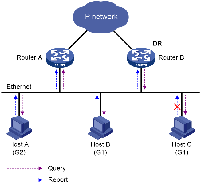
As shown in Figure 1, Host B and Host C are interested in the multicast data addressed to the multicast group G1. Host A is interested in the multicast data addressed to G2. The following process describes how the hosts join the multicast groups and how the IGMP querier (Router B in Figure 1) maintains the multicast group memberships:
1. The hosts send unsolicited IGMP reports to the multicast groups they want to join without having to wait for the IGMP queries.
2. The IGMP querier periodically multicasts IGMP queries (with the destination address of 224.0.0.1) to all hosts and routers on the local subnet.
3. After receiving a query message, the host whose report delay timer expires first sends an IGMP report to multicast group G1 to announce its membership for G1. In this example, Host B sends the report message. After receiving the report from Host B, Host C suppresses its own report for G1.
Because IGMP routers already know that G1 has a minimum of one member, other members do not need to report their memberships. This mechanism, known as the host IGMP report suppression, helps reduce traffic on the local subnet.
4. At the same time, Host A sends a report to the multicast group G2 after receiving a query.
5. Through the query and response process, the IGMP routers (Router A and Router B) determine that the local subnet has members of G1 and G2. The multicast routing protocol (PIM, for example) on the routers generates (*, G1) and (*, G2) multicast forwarding entries, where asterisk (*) represents any multicast source. These entries are the basis for subsequent multicast forwarding.
6. When the multicast data addressed to G1 or G2 reaches an IGMP router, the router looks up the multicast forwarding table. Based on the (*, G1) or (*, G2) entries, the router forwards the multicast data to the local subnet. Then, the receivers on the subnet can receive the data.
IGMPv1 does not define a leave group message (often called a leave message). When an IGMPv1 host is leaving a multicast group, it stops sending reports to that multicast group. If the subnet has no members for a multicast group, the IGMP routers will not receive any report addressed to that multicast group. In this case, the routers clear the information for that multicast group after a period of time.
IGMPv2 enhancements
Backwards-compatible with IGMPv1, IGMPv2 has introduced a querier election mechanism and a leave-group mechanism.
Querier election mechanism
In IGMPv1, the DR elected by the Layer 3 multicast routing protocol (such as PIM) acts as the querier.
IGMPv2 introduced an independent querier election mechanism. The querier election process is as follows:
1. Initially, every IGMPv2 router assumes itself to be the querier. Each router sends IGMP general query messages (called general queries) to all hosts and routers on the local subnet. The destination address is 224.0.0.1.
2. After receiving a general query, every IGMPv2 router compares the source IP address of the query with its own interface address. The router with the lowest IP address becomes the querier. All the other IGMPv2 routers become non-queriers.
3. All the non-queriers start the other querier present timer. If a router receives an IGMP query from the querier before the timer expires, it resets this timer. Otherwise, the router considers that the querier has timed out. In this case, the router initiates a new querier election process.
"Leave group" mechanism
In IGMPv1, when a host leaves a multicast group, it does not send any notification to the multicast routers. The multicast routers determine whether a group has members by using the maximum response time. This adds to the leave latency.
In IGMPv2, when a host is leaving a multicast group, the following process occurs:
1. The host sends a leave message to all routers on the local subnet. The destination address of leave messages is 224.0.0.2.
2. After receiving the leave message, the querier sends a configurable number of IGMP group-specific queries to the group that the host is leaving. Both the destination address field and the group address field of the message are the address of the multicast group that is being queried.
3. One of the remaining members (if any on the subnet) in the group should send a report within the maximum response time advertised in the group-specific queries.
4. If the querier receives a report for the group before the maximum response timer expires, it maintains the memberships for the group. Otherwise, the querier assumes that the local subnet has no member hosts for the group and stops maintaining the memberships for the group.
IGMPv3 enhancements
IGMPv3 is based on and is compatible with IGMPv1 and IGMPv2. It enhances the control capabilities of hosts and the query and report capabilities of IGMP routers.
Enhancements in control capability of hosts
IGMPv3 introduced two source filtering modes (Include and Exclude). These modes allow a host to receive or reject multicast data from the specified multicast sources. When a host joins a multicast group, one of the following occurs:
· If the host expects to receive multicast data from specific sources like S1, S2, …, it sends a report with the Filter-Mode denoted as "Include Sources (S1, S2, …)."
· If the host expects to reject multicast data from specific sources like S1, S2, …, it sends a report with the Filter-Mode denoted as "Exclude Sources (S1, S2, …)."
As shown in Figure 2, the network has two multicast sources: Source 1 (S1) and Source 2 (S2). Both of these sources can send multicast data to the multicast group G. Host B wants to receive the multicast data addressed to G from Source 1 but not from Source 2.
Figure 2 Flow paths of source-and-group-specific multicast traffic
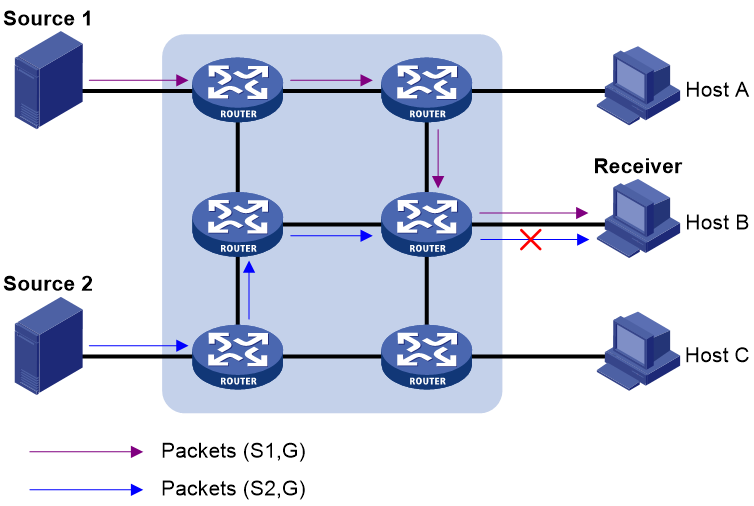
In IGMPv1 or IGMPv2, Host B cannot select multicast sources when it joins the multicast group G. The multicast streams from both Source 1 and Source 2 flow to Host B whether or not it needs them.
In IGMPv3, Host B can explicitly express that it needs to receive multicast data destined to the multicast group G from Source 1 but not from Source 2.
Enhancements in query and report capabilities
IGMPv3 introduces IGMP group-and-source queries and IGMP reports carrying group records.
· Query message carrying the source addresses
IGMPv3 is compatible with IGMPv1 and IGMPv2 and supports IGMP general queries and IGMP group-specific queries. It also introduces IGMP group-and-source-specific queries.
¡ A general query does not carry a group address or a source address.
¡ A group-specific query carries a group address, but no source address.
¡ A group-and-source-specific query carries a group address and one or more source addresses.
· Reports containing multiple group records
Unlike an IGMPv1 or IGMPv2 report, an IGMPv3 report is destined to 224.0.0.22 and contains one or more group records. Each group record contains a multicast group address and a multicast source address list.
Group records include the following categories:
¡ IS_IN—The current filtering mode is Include. The report sender requests the multicast data only from the sources specified in the Source Address field.
¡ IS_EX—The current filtering mode is Exclude. The report sender requests the multicast data from any sources except those specified in the Source Address field.
¡ TO_IN—The filtering mode has changed from Exclude to Include.
¡ TO_EX—The filtering mode has changed from Include to Exclude.
¡ ALLOW—The Source Address field contains a list of additional sources from which the receiver wants to obtain data. If the current filtering mode is Include, these sources are added to the multicast source list. If the current filtering mode is Exclude, these sources are deleted from the multicast source list.
¡ BLOCK—The Source Address field contains a list of the sources from which the receiver no longer wants to obtain data. If the current filtering mode is Include, these sources are deleted from the multicast source list. If the current filtering mode is Exclude, these sources are added to the multicast source list.
IGMP SSM mapping
An IGMPv3 host can explicitly specify multicast sources in its IGMPv3 reports. From the reports, the IGMP router can obtain the multicast source addresses and directly provide the SSM service. However, an IGMPv1 or IGMPv2 host cannot specify multicast sources in its IGMPv1 or IGMPv2 reports.
The IGMP SSM mapping feature enables the IGMP router to provide SSM support for IGMPv1 or IGMPv2 hosts. The router translates (*, G) in IGMPv1 or IGMPv2 reports into (G, INCLUDE, (S1, S2...)) based on the configured IGMP SSM mappings.
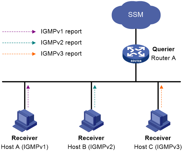
As shown in Figure 3, on an SSM network, Host A, Host B, and Host C run IGMPv1, IGMPv2, and IGMPv3, respectively. To provide the SSM service for Host A and Host B, you must configure the IGMP SSM mapping feature on Router A.
After IGMP SSM mappings are configured, Router A checks the multicast group address G in the received IGMPv1 or IGMPv2 report, and performs the following operations:
· If G is not in the SSM group range, Router A provides the ASM service.
· If G is in the SSM group range but does not match any IGMP SSM mapping, Router A drops the report.
· If G is in the SSM group range and matches IGMP SSM mappings, Router A translates (*, G) in the report into (G, INCLUDE, (S1, S2...)) to provide SSM services.
|
NOTE: The IGMP SSM mapping feature does not process IGMPv3 reports. |
For more information about SSM group ranges, see "Configuring PIM."
IGMP proxying
As shown in Figure 4, in a simple tree-shaped topology, it is not necessary to run multicast routing protocols, such as PIM, on edge devices. Instead, you can configure IGMP proxying on these devices. With IGMP proxying configured, the edge device acts as an IGMP proxy:
· For the upstream IGMP querier, the IGMP proxy device acts as a host.
· For the downstream receiver hosts, the IGMP proxy device acts as an IGMP querier.
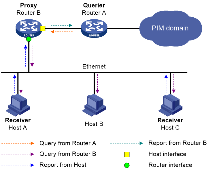
The following types of interfaces are defined in IGMP proxying:
· Host interface—An interface that is in the direction toward the root of the multicast forwarding tree. A host interface acts as a receiver host that is running IGMP. IGMP proxying must be enabled on this interface. This interface is also called the "proxy interface."
· Router interface—An interface that is in the direction toward the leaf of the multicast forwarding tree. A router interface acts as a router that is running IGMP. IGMP must be configured on this interface.
An IGMP proxy device maintains a group membership database, which stores the group memberships on all the router interfaces. The host interfaces and router interfaces perform actions based on this membership database.
· The host interfaces respond to queries according to the membership database or send join/leave messages when the database changes.
· The router interfaces participate in the querier election, send queries, and maintain memberships based on received IGMP reports.
IGMP support for VPNs
IGMP maintains group memberships on a per-interface basis. After receiving an IGMP message on an interface, IGMP processes the packet within the VPN to which the interface belongs. IGMP only communicates with other multicast protocols within the same VPN instance.
Protocols and standards
· RFC 1112, Host Extensions for IP Multicasting
· RFC 2236, Internet Group Management Protocol, Version 2
· RFC 3376, Internet Group Management Protocol, Version 3
IGMP configuration task list
|
Tasks at a glance |
|
Configuring basic IGMP features: · (Required.) Enabling IGMP · (Optional.) Specifying an IGMP version · (Optional.) Configuring a static group member · (Optional.) Configuring a multicast group policy |
|
(Optional.) Adjusting IGMP performance: |
|
(Optional.) Configuring IGMP SSM mappings |
|
(Optional.) Configuring IGMP proxying: |
|
(Optional.) Enabling IGMP NSR |
|
(Optional.) Setting the DSCP value for outgoing IGMP protocol packets |
Configuring basic IGMP features
Before you configure basic IGMP features, complete the following tasks:
· Configure any unicast routing protocol so that all devices can interoperate at the network layer.
· Configure PIM.
· Determine the IGMP version.
· Determine the multicast group and multicast source addresses for static group member configuration.
· Determine the ACL to be used in the multicast group policy.
Enabling IGMP
Enable IGMP on the interface where the multicast group memberships are established and maintained.
To enable IGMP:
|
Step |
Command |
Remarks |
|
1. Enter system view. |
system-view |
N/A |
|
2. Enable IP multicast routing and enter MRIB view. |
multicast routing [ vpn-instance vpn-instance-name ] |
By default, IP multicast routing is disabled. |
|
3. Return to system view. |
quit |
N/A |
|
4. Enter interface view. |
interface interface-type interface-number |
N/A |
|
5. Enable IGMP. |
igmp enable |
By default, IGMP is disabled. |
Specifying an IGMP version
For IGMP to operate correctly, specify the same IGMP version for all routers on the same subnet.
To specify an IGMP version:
|
Step |
Command |
Remarks |
|
6. Enter system view. |
system-view |
N/A |
|
7. Enter interface view. |
interface interface-type interface-number |
N/A |
|
8. Specify an IGMP version on the interface. |
igmp version version-number |
The default setting is 2. |
Configuring a static group member
You can configure an interface as a static group member of a multicast group. Then, the interface can always receive multicast data addressed to the specified multicast group.
A static group member does not respond to IGMP queries. When you complete or cancel this configuration on an interface, the interface does not send an unsolicited IGMP report or leave message.
Configuration restrictions and guidelines
The interface to be configured as a static group member has the following restrictions:
· If the interface is IGMP and PIM-SM enabled, it must be a PIM-SM DR.
· If the interface is IGMP enabled but not PIM-SM enabled, it must be an IGMP querier.
For more information about PIM-SM and DR, see "Configuring PIM."
Configuration procedure
To configure a static group member:
|
Step |
Command |
Remarks |
|
1. Enter system view. |
system-view |
N/A |
|
2. Enter interface view. |
interface interface-type interface-number |
N/A |
|
3. Configure the interface as a static group member. |
igmp static-group group-address [ source source-address ] |
By default, an interface is not a static group member of any multicast groups. |
Configuring a multicast group policy
This feature enables an interface to filter IGMP reports by using an ACL that specifies multicast groups and the optional sources. It is used to control the multicast groups that the hosts attached to an interface can join.
This configuration does not take effect on static group members, because static group members do not send IGMP reports.
To configure a multicast group policy:
|
Step |
Command |
Remarks |
|
1. Enter system view. |
system-view |
N/A |
|
2. Enter interface view. |
interface interface-type interface-number |
N/A |
|
3. Configure a multicast group policy. |
igmp group-policy ipv4-acl-number [ version-number ] |
By default, no IGMP multicast group policy exists on an interface. Hosts attached to the interface can join any multicast groups. |
Adjusting IGMP performance
Before adjusting IGMP performance, complete the following tasks:
· Configure any unicast routing protocol so that all devices can interoperate at the network layer.
· Configure basic IGMP features.
Configuring IGMP query and response parameters
The following are IGMP query and response parameters:
· IGMP querier's robustness variable—Number of times for retransmitting IGMP queries in case of packet loss. A higher robustness variable makes the IGMP querier more robust, but increases the timeout time for multicast groups.
· IGMP startup query interval—Interval at which an IGMP querier sends IGMP general queries at startup.
· IGMP startup query count—Number of IGMP general queries that an IGMP querier sends at startup.
· IGMP general query interval—Interval at which an IGMP querier sends IGMP general queries to check for multicast group members on the network.
· IGMP last member query interval—In IGMPv2, it sets the interval at which a querier sends group-specific queries after receiving a leave message. In IGMPv3, it sets the interval at which a querier sends group-and-source-specific queries after receiving a report that changes multicast source and group mappings.
· IGMP last member query count—In IGMPv2, it sets the number of group-specific queries that a querier sends after receiving a leave message. In IGMPv3, it sets the number of group-and-source-specific queries that a querier sends after receiving a report that changes multicast source and group mappings.
· IGMP maximum response time—Maximum time before a receiver responds with a report to an IGMP general query. This per-group timer is initialized to a random value in the range of 0 to the maximum response time specified in the IGMP query. When the timer value for a group decreases to 0, the receiver sends an IGMP report to the group.
· IGMP other querier present timer—Lifetime for an IGMP querier after a non-querier receives an IGMP general query. If the non-querier does not receive a new query when this timer expires, the non-querier considers that the querier has failed and starts a new querier election.
Configuration restrictions and guidelines
When you configure the IGMP query and response parameters, follow these restrictions and guidelines:
· You can configure the IGMP query and response parameters globally for all interfaces in IGMP view or for an interface in interface view. For an interface, the interface-specific configuration takes priority over the global configuration.
· To avoid frequent IGMP querier changes, set the IGMP other querier present timer greater than the IGMP general query interval. In addition, configure the same IGMP other querier present timer for all IGMP routers on the same subnet.
· To avoid mistakenly deleting multicast receivers, set the IGMP general query interval greater than the maximum response time for IGMP general queries.
· To speed up the response to IGMP queries and avoid simultaneous timer expirations that cause IGMP report traffic bursts, set an appropriate maximum response time.
¡ For IGMP general queries, the maximum response time is set by the max-response-time command.
¡ For IGMP group-specific queries and IGMP group-and-source-specific queries, the maximum response time equals the IGMP last member query interval.
· The following configurations take effect only on the devices that run IGMPv2 and IGMPv3:
¡ Maximum response time for IGMP general queries.
¡ IGMP last member query interval.
¡ IGMP last member query count.
¡ IGMP other querier present interval.
Configuring the IGMP query and response parameters globally
|
Step |
Command |
Remarks |
|
1. Enter system view. |
system-view |
N/A |
|
2. Enter IGMP view. |
igmp [ vpn-instance vpn-instance-name ] |
N/A |
|
3. Set the IGMP querier's robustness variable. |
robust-count count |
By default, the IGMP querier's robustness variable is 2. |
|
4. Set the IGMP startup query interval. |
startup-query-interval interval |
By default, the IGMP startup query interval equals one quarter of the IGMP general query interval. |
|
5. Set the IGMP startup query count. |
startup-query-count count |
By default, the IGMP startup query count equals the IGMP querier's robustness variable. |
|
6. Set the IGMP general query interval. |
query-interval interval |
By default, the IGMP general query interval is 125 seconds. |
|
7. Set the IGMP last member query interval. |
last-member-query-interval interval |
By default, the IGMP last member query interval is 1 second. |
|
8. Set the IGMP last member query count. |
last-member-query-count count |
By default, the IGMP last member query count equals the IGMP querier's robustness variable. |
|
9. Set the maximum response time for IGMP general queries. |
max-response-time time |
By default, the maximum response time for IGMP general queries is 10 seconds. |
|
10. Set the IGMP other querier present timer. |
other-querier-present-interval interval |
By default, the IGMP other querier
present timer is calculated by using the following formula: |
Configuring the IGMP query and response parameters on an interface
|
Step |
Command |
Remarks |
|
1. Enter system view. |
system-view |
N/A |
|
2. Enter interface view. |
interface interface-type interface-number |
N/A |
|
3. Set the IGMP querier's robustness variable. |
igmp robust-count count |
By default, the IGMP querier's robustness variable is 2. |
|
4. Set the IGMP startup query interval. |
igmp startup-query-interval interval |
By default, the IGMP startup query interval equals one quarter of the IGMP general query interval. |
|
5. Set the IGMP startup query count. |
igmp startup-query-count count |
By default, the IGMP startup query count equals the IGMP querier's robustness variable. |
|
6. Set the IGMP general query interval. |
igmp query-interval interval |
By default, the IGMP general query interval is 125 seconds. |
|
7. Set the IGMP last member query interval. |
igmp last-member-query-interval interval |
By default, the IGMP last member query interval is 1 second. |
|
8. Set the IGMP last member query count. |
igmp last-member-query-count count |
By default, the IGMP last member query count equals the IGMP querier's robustness variable. |
|
9. Set the maximum response time for IGMP general queries. |
igmp max-response-time time |
By default, the maximum response time for IGMP general queries is 10 seconds. |
|
10. Set the IGMP other querier present timer. |
igmp other-querier-present-interval interval |
By default, the IGMP other querier
present timer is calculated by using the following formula: |
Enabling fast-leave processing
This feature enables an IGMP querier to send leave notifications to the upstream without sending group-specific or group-and-source-specific queries after receiving a leave message. Use this feature to reduce leave latency and to preserve the network bandwidth.
The fast-leave processing configuration takes effect only when the device runs IGMPv2 or IGMPv3.
To enable fast-leave processing:
|
Step |
Command |
Remarks |
|
1. Enter system view. |
system-view |
N/A |
|
2. Enter interface view. |
interface interface-type interface-number |
N/A |
|
3. Enable fast-leave processing. |
igmp fast-leave [ group-policy ipv4-acl-number ] |
By default, fast-leave processing is disabled. |
Configuring IGMP SSM mappings
This feature enables the device to provide SSM services for IGMPv1 or IGMPv2 hosts.
This feature does not process IGMPv3 messages. Enable IGMPv3 on the receiver-side interface to ensure that IGMPv3 reports can be processed.
Configuration prerequisites
Before you configure IGMP SSM mappings, complete the following tasks:
· Configure any unicast routing protocol so that all devices in the domain can interoperate at the network layer.
· Configure basic IGMP features.
Configuration procedure
To configure an IGMP SSM mapping:
|
Step |
Command |
Remarks |
|
1. Enter system view. |
system-view |
N/A |
|
2. Enter IGMP view. |
igmp [ vpn-instance vpn-instance-name ] |
N/A |
|
3. Configure an IGMP SSM mapping. |
ssm-mapping source-address ipv4-acl-number |
By default, no IGMP SSM mappings exist. |
Configuring IGMP proxying
This section describes how to configure IGMP proxying.
Configuration prerequisites
Before you configure the IGMP proxying feature, complete the following tasks:
1. Configure a unicast routing protocol so that all devices in the domain can interoperate at the network layer.
2. Determine the router interfaces and host interfaces based on the network topology.
3. Enable IGMP on the router interfaces.
Enabling IGMP proxying
When you enable IGMP proxying, follow these restrictions and guidelines:
· You must enable IGMP proxying on the receiver-side interfaces.
· On an interface enabled with IGMP proxying, only the igmp version command takes effect and other IGMP commands do not take effect.
· If you enable both IGMP proxying and a multicast routing protocol (such as PIM or MSDP) on the same device, the multicast routing protocol does not take effect.
In IGMPv1, the DR is elected by PIM and acts as the IGMP querier. Because PIM does not take effect on a proxy device, a router interface running IGMPv1 cannot be elected as the DR. To ensure that the downstream receiver hosts on the router interface can receive multicast data, you must enable multicast forwarding on the interface. For more information, see "Enabling multicast forwarding on a non-querier interface."
To enable IGMP proxying:
|
Step |
Command |
Remarks |
|
1. Enter system view. |
system-view |
N/A |
|
2. Enable IP multicast routing and enter MRIB view. |
multicast routing [ vpn-instance vpn-instance-name ] |
By default, IP multicast routing is disabled. |
|
3. Return to system view. |
quit |
N/A |
|
4. Enter interface view. |
interface interface-type interface-number |
N/A |
|
5. Enable IGMP proxying. |
igmp proxying enable |
By default, IGMP proxying is disabled. |
Enabling multicast forwarding on a non-querier interface
Typically, only IGMP queriers can forward multicast traffic and non-queriers cannot. This prevents multicast data from being repeatedly forwarded. If a router interface on an IGMP proxy device failed in the querier election, enable multicast forwarding on the interface to forward multicast data to attached receiver hosts.
Configuration restrictions and guidelines
A shared-media network might have multiple IGMP proxies, including one proxy acting as a querier. To avoid duplicate multicast traffic, do not enable multicast forwarding on any of the non-querier IGMP proxies for the network.
Configuration procedure
To enable multicast forwarding on a non-querier interface:
|
Step |
Command |
Remarks |
|
1. Enter system view. |
system-view |
N/A |
|
2. Enter interface view. |
interface interface-type interface-number |
N/A |
|
3. Enable multicast forwarding on the interface. |
igmp proxy forwarding |
By default, multicast forwarding is disabled on a non-querier interface. |
Configuring multicast load splitting on an IGMP proxy
This feature enables all proxy interfaces on an IGMP proxy device to share multicast traffic on a per-group basis.
To enable multicast load splitting on an IGMP proxy device:
|
Step |
Command |
Remarks |
|
1. Enter system view. |
system-view |
N/A |
|
2. Enter IGMP view. |
igmp [ vpn-instance vpn-instance-name ] |
N/A |
|
3. Enable multicast load splitting. |
proxy multipath |
By default, multicast load splitting is disabled, and only the proxy interface with the highest IP address on the IGMP proxy device forwards multicast data. |
Enabling IGMP NSR
This feature backs up information about IGMP interfaces and IGMP multicast groups to the standby process. The device recovers the information without cooperation of other devices when an active/standby switchover occurs. Use this feature to prevent an active/standby switchover from affecting the multicast service.
To enable IGMP NSR:
|
Step |
Command |
Remarks |
|
1. Enter system view. |
system-view |
N/A |
|
2. Enable IGMP NSR. |
igmp non-stop-routing |
By default, IGMP NSR is disabled. |
Setting the DSCP value for outgoing IGMP protocol packets
The DSCP value determines the packet transmission priority. A greater DSCP value represents a higher priority.
To set the DSCP value for outgoing IGMP protocol packets:
|
Step |
Command |
Remarks |
|
1. Enter system view. |
system-view |
N/A |
|
2. Enter IGMP view. |
igmp [ vpn-instance vpn-instance-name ] |
N/A |
|
3. Set the DSCP value for outgoing IGMP protocol packets. |
dscp dscp-value |
The default setting is 48. |
Displaying and maintaining IGMP
|
|
CAUTION: The reset igmp group command might cause multicast data transmission failures. |
Execute display commands in any view and reset commands in user view.
|
Task |
Command |
|
Display information about IGMP multicast groups. |
display igmp [ vpn-instance vpn-instance-name ] group [ group-address | interface interface-type interface-number ] [ static | verbose ] |
|
Display IGMP information for interfaces. |
display igmp [ vpn-instance vpn-instance-name ] interface [ interface-type interface-number ] [ host | proxy ] [ verbose ] |
|
Display multicast group membership information maintained by the IGMP proxy. |
display igmp [ vpn-instance vpn-instance-name ] proxy group [ group-address | interface interface-type interface-number ] [ verbose ] |
|
Display multicast routing entries maintained by the IGMP proxy. |
display igmp [ vpn-instance vpn-instance-name ] proxy routing-table [ source-address [ mask { mask-length | mask } ] | group-address [ mask { mask-length | mask } ] ] * [ verbose ] |
|
Display IGMP SSM mappings. |
display igmp [ vpn-instance vpn-instance-name ] ssm-mapping group-address |
|
Clear dynamic IGMP multicast group entries. |
reset igmp [ vpn-instance vpn-instance-name ] group { all | interface interface-type interface-number { all | group-address [ mask { mask | mask-length } ] [ source-address [ mask { mask | mask-length } ] ] } } |
IGMP configuration examples
This section provides examples of configuring IGMP on switches.
Basic IGMP features configuration example
Network requirements
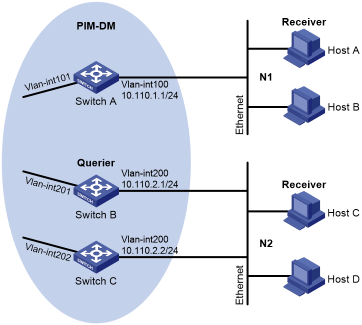
As shown in Figure 5:
· OSPF and PIM-DM run on the network.
· VOD streams are sent to receiver hosts in multicast. Receiver hosts of different organizations form stub networks N1 and N2. Host A and Host C are receiver hosts in N1 and N2, respectively.
· IGMPv2 runs between Switch A and N1, and between the other two switches and N2. Switch A acts as the IGMP querier in N1. Switch B acts as the IGMP querier in N2 because it has a lower IP address.
Configure the routers to meet the following requirements:
· The hosts in N1 can join only multicast group 224.1.1.1.
· The hosts in N2 can join any multicast groups.
Configuration procedure
1. Assign an IP address and subnet mask to each interface, as shown in Figure 5. (Details not shown.)
2. Configure OSPF on the switches in the PIM-DM domain. (Details not shown.)
3. Enable IP multicast routing, IGMP, and PIM-DM:
# On Switch A, enable IP multicast routing.
<SwitchA> system-view
[SwitchA] multicast routing
[SwitchA-mrib] quit
# Enable IGMP on VLAN-interface 100.
[SwitchA] interface vlan-interface 100
[SwitchA-Vlan-interface100] igmp enable
[SwitchA-Vlan-interface100] quit
# Enable PIM-DM on VLAN-interface 101.
[SwitchA] interface vlan-interface 101
[SwitchA-Vlan-interface101] pim dm
[SwitchA-Vlan-interface101] quit
# On Switch B, enable IP multicast routing.
<SwitchB> system-view
[SwitchB] multicast routing
[SwitchB-mrib] quit
# Enable IGMP on VLAN-interface 200.
[SwitchB] interface vlan-interface 200
[SwitchB-Vlan-interface200] igmp enable
[SwitchB-Vlan-interface200] quit
# Enable PIM-DM on VLAN-interface 201.
[SwitchB] interface vlan-interface 201
[SwitchB-Vlan-interface201] pim dm
[SwitchB-Vlan-interface201] quit
# On Switch C, enable IP multicast routing.
<SwitchC> system-view
[SwitchC] multicast routing
[SwitchC-mrib] quit
# Enable IGMP on VLAN-interface 200.
[SwitchC] interface vlan-interface 200
[SwitchC-Vlan-interface200] igmp enable
[SwitchC-Vlan-interface200] quit
# Enable PIM-DM on VLAN-interface 202.
[SwitchC] interface vlan-interface 202
[SwitchC-Vlan-interface202] pim dm
[SwitchC-Vlan-interface202] quit
4. Configure a multicast group policy on Switch A so that hosts connected to VLAN-interface 100 can join only multicast group 224.1.1.1.
[SwitchA] acl basic 2001
[SwitchA-acl-ipv4-basic-2001] rule permit source 224.1.1.1 0
[SwitchA-acl-ipv4-basic-2001] quit
[SwitchA] interface vlan-interface 100
[SwitchA-Vlan-interface100] igmp group-policy 2001
[SwitchA-Vlan-interface100] quit
Verifying the configuration
# Display IGMP information for VLAN-interface 200 on Switch B.
[SwitchB] display igmp interface vlan-interface 200
Vlan-interface200(10.110.2.1):
IGMP is enabled.
IGMP version: 2
Query interval for IGMP: 125s
Other querier present time for IGMP: 255s
Maximum query response time for IGMP: 10s
Querier for IGMP: 10.110.2.1 (This router)
IGMP groups reported in total: 1
IGMP SSM mapping configuration example
Network requirements
As shown in Figure 6:
· OSPF runs on the network.
· The PIM-SM domain uses both the ASM model and SSM model for multicast delivery. VLAN-interface 104 on Switch D acts as the C-BSR and C-RP. The SSM group range is 232.1.1.0/24.
· IGMPv3 runs on VLAN-interface 400 of Switch D. The receiver host runs IGMPv2, and does not support IGMPv3. The receiver host cannot specify multicast sources in its membership reports.
· Source 1, Source 2, and Source 3 send multicast packets to multicast groups in the SSM group range 232.1.1.0/24.
Configure the IGMP SSM mapping feature on Switch D so that the receiver host can receive multicast data only from Source 1 and Source 3.
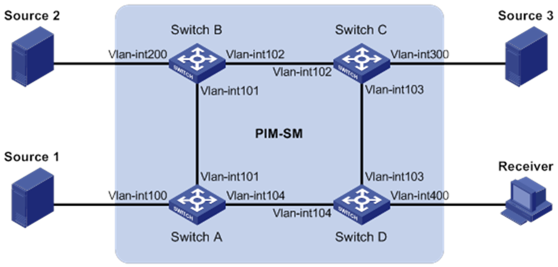
Table 1 Interface and IP address assignment
|
Device |
Interface |
IP address |
Device |
Interface |
IP address |
|
Source 1 |
— |
133.133.1.1/24 |
Source 3 |
— |
133.133.3.1/24 |
|
Source 2 |
— |
133.133.2.1/24 |
Receiver |
— |
133.133.4.1/24 |
|
Switch A |
Vlan-int100 |
133.133.1.2/24 |
Switch C |
Vlan-int300 |
133.133.3.2/24 |
|
Switch A |
Vlan-int101 |
192.168.1.1/24 |
Switch C |
Vlan-int103 |
192.168.3.1/24 |
|
Switch A |
Vlan-int104 |
192.168.4.2/24 |
Switch C |
Vlan-int102 |
192.168.2.2/24 |
|
Switch B |
Vlan-int200 |
133.133.2.2/24 |
Switch D |
Vlan-int400 |
133.133.4.2/24 |
|
Switch B |
Vlan-int101 |
192.168.1.2/24 |
Switch D |
Vlan-int103 |
192.168.3.2/24 |
|
Switch B |
Vlan-int102 |
192.168.2.1/24 |
Switch D |
Vlan-int104 |
192.168.4.1/24 |
Configuration procedure
1. Assign an IP address and subnet mask to each interface, as shown in Figure 6. (Details not shown.)
2. Configure OSPF on the switches in the PIM-SM domain. (Details not shown.)
3. Enable IP multicast routing, PIM-SM, and IGMP:
# On Switch D, enable IP multicast routing.
<SwitchD> system-view
[SwitchD] multicast routing
[SwitchD-mrib] quit
# Enable IGMPv3 on the receiver-side interface (VLAN-interface 400).
[SwitchD] interface vlan-interface 400
[SwitchD-Vlan-interface400] igmp enable
[SwitchD-Vlan-interface400] igmp version 3
[SwitchD-Vlan-interface400] quit
# Enable PIM-SM on the other interfaces.
[SwitchD] interface vlan-interface 103
[SwitchD-Vlan-interface103] pim sm
[SwitchD-Vlan-interface103] quit
[SwitchD] interface vlan-interface 104
[SwitchD-Vlan-interface104] pim sm
[SwitchD-Vlan-interface104] quit
# On Switch A, enable IP multicast routing.
<SwitchA> system-view
[SwitchA] multicast routing
[SwitchA-mrib] quit
# Enable PIM-SM on each interface.
[SwitchA] interface vlan-interface 100
[SwitchA-Vlan-interface100] pim sm
[SwitchA-Vlan-interface100] quit
[SwitchA] interface vlan-interface 101
[SwitchA-Vlan-interface101] pim sm
[SwitchA-Vlan-interface101] quit
[SwitchA] interface vlan-interface 104
[SwitchA-Vlan-interface104] pim sm
[SwitchA-Vlan-interface104] quit
# Configure Switch B and Switch C in the same way Switch A is configured. (Details not shown.)
4. On Switch D, configure VLAN-interface 104 as a C-BSR and a C-RP.
[SwitchD] pim
[SwitchD-pim] c-bsr 192.168.4.1
[SwitchD-pim] c-rp 192.168.4.1
[SwitchD-pim] quit
5. Configure the SSM group range:
# On Switch D, specify 232.1.1.0/24 as the SSM group range.
[SwitchD] acl basic 2000
[SwitchD-acl-ipv4-basic-2000] rule permit source 232.1.1.0 0.0.0.255
[SwitchD-acl-ipv4-basic-2000] quit
[SwitchD] pim
[SwitchD-pim] ssm-policy 2000
[SwitchD-pim] quit
# Configure the SSM group range on Switch A, Switch B, and Switch C in the same way Switch D is configured. (Details not shown.)
6. Configure IGMP SSM mappings on Switch D.
[SwitchD] igmp
[SwitchD-igmp] ssm-mapping 133.133.1.1 2000
[SwitchD-igmp] ssm-mapping 133.133.3.1 2000
[SwitchD-igmp] quit
Verifying the configuration
# Display IGMP SSM mappings for multicast group 232.1.1.1 on Switch D.
[SwitchD] display igmp ssm-mapping 232.1.1.1
Group: 232.1.1.1
Source list:
133.133.1.1
133.133.3.1
# On Switch D, display information about IGMP multicast groups that hosts have dynamically joined.
[SwitchD] display igmp group
IGMP groups in total: 1
Vlan-interface400(133.133.4.2):
IGMP groups reported in total: 1
Group address Last reporter Uptime Expires
232.1.1.1 133.133.4.1 00:02:04 off
# Display PIM routing entries on Switch D.
[SwitchD] display pim routing-table
Total 0 (*, G) entry; 2 (S, G) entry
(133.133.1.1, 232.1.1.1)
RP: 192.168.4.1
Protocol: pim-ssm, Flag:
UpTime: 00:13:25
Upstream interface: Vlan-interface104
Upstream neighbor: 192.168.4.2
RPF prime neighbor: 192.168.4.2
Downstream interface(s) information:
Total number of downstreams: 1
1: Vlan-interface400
Protocol: igmp, UpTime: 00:13:25, Expires: -
(133.133.3.1, 232.1.1.1)
RP: 192.168.4.1
Protocol: pim-ssm, Flag:
UpTime: 00:13:25
Upstream interface: Vlan-interface103
Upstream neighbor: 192.168.3.1
RPF prime neighbor: 192.168.3.1
Downstream interface(s) information:
Total number of downstreams: 1
1: Vlan-interface400
Protocol: igmp, UpTime: 00:13:25, Expires: -
IGMP proxying configuration example
Network requirements
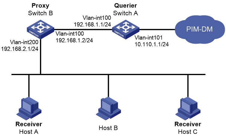
As shown in Figure 7:
· PIM-DM runs on the core network.
· Host A and Host C on the stub network receive VOD information sent to multicast group 224.1.1.1.
Configure the IGMP proxying feature on Switch B so that Switch B can maintain group memberships and forward multicast traffic without running PIM-DM.
Configuration procedure
1. Assign an IP address and subnet mask to each interface, as shown in Figure 7. (Details not shown.)
2. Enable IP multicast routing, PIM-DM, IGMP, and IGMP proxying:
# On Switch A, enable IP multicast routing.
<SwitchA> system-view
[SwitchA] multicast routing
[SwitchA-mrib] quit
# Enable PIM-DM on VLAN-interface 101.
[SwitchA] interface vlan-interface 101
[SwitchA-Vlan-interface101] pim dm
[SwitchA-Vlan-interface101] quit
# Enable IGMP on VLAN-interface 100.
[SwitchA] interface vlan-interface 100
[SwitchA-Vlan-interface100] igmp enable
[SwitchA-Vlan-interface100] quit
# On Switch B, enable IP multicast routing.
<SwitchB> system-view
[SwitchB] multicast routing
[SwitchB-mrib] quit
# Enable IGMP proxying on VLAN-interface 100.
[SwitchB] interface vlan-interface 100
[SwitchB-Vlan-interface100] igmp proxy enable
[SwitchB-Vlan-interface100] quit
# Enable IGMP on VLAN-interface 200.
[SwitchB] interface vlan-interface 200
[SwitchB-Vlan-interface200] igmp enable
[SwitchB-Vlan-interface200] quit
Verifying the configuration
# Display multicast group membership information maintained by the IGMP proxy on Switch B.
[SwitchB] display igmp proxy group
IGMP proxy group records in total: 1
Vlan-interface100(192.168.1.2):
IGMP proxy group records in total: 1
Group address Member state Expires
224.1.1.1 Delay 00:00:02
Troubleshooting IGMP
No membership information on the receiver-side router
Symptom
When a host sends a report for joining multicast group G, no membership information of multicast group G exists on the router closest to that host.
Solution
To resolve the problem:
1. Use the display igmp interface command to verify that the networking, interface connection, and IP address configuration are correct.
2. Use the display current-configuration command to verify that multicast routing is enabled. If it is not enabled, use the multicast routing command in system view to enable IP multicast routing. In addition, verify that IGMP is enabled on the associated interfaces.
3. Use the display igmp interface command to verify that the IGMP version on the interface is lower than that on the host.
4. Use the display current-configuration interface command to verify that no multicast group policies have been configured to filter IGMP reports for multicast group G.
5. If the problem persists, contact H3C Support.
Inconsistent membership information on the routers on the same subnet
Symptom
Different memberships are maintained on different IGMP routers on the same subnet.
Solution
To resolve the problem:
1. Use the display current-configuration command to verify the IGMP information on the interfaces. Make sure the routers on the subnet have the same IGMP settings on their interfaces.
2. Use the display igmp interface command on all routers on the same subnet to verify the IGMP-related timer settings. Make sure the settings are consistent on all the routers.
3. Use the display igmp interface command to verify that all routers on the same subnet are running the same IGMP version.
4. If the problem persists, contact H3C Support.