- Table of Contents
- Related Documents
-
| Title | Size | Download |
|---|---|---|
| 02-Hardware Information and Specifications | 1.06 MB |
1 Product models and technical specifications
10/100/1000BASE-T autosensing Ethernet port
10/100/1000BASE-T autosensing Ethernet port LED
Fan tray status LED on the fan tray
1 Product models and technical specifications
Product models
H3C S5850 Switch Series includes only the S5850-54QS switch model.
Technical specifications
Table1-1 Technical specifications
|
Item |
Specification |
|
Dimensions (H × W × D) |
43.6 × 440 × 360 mm (1.72 × 17.32 × 14.17 in) |
|
Weight |
≤ 7.5 kg (16.53 lb) |
|
Console ports |
· 1 × Mini USB console port · 1 × serial console port Only the Mini USB console port is available when you connect both ports. |
|
USB ports |
1 |
|
Management Ethernet ports |
2 |
|
QSFP+ ports |
2 |
|
SFP+ ports |
4 |
|
10/100/1000BASE-T autosensing Ethernet ports |
48 |
|
Power module slots |
2, on the rear panel |
|
Fan tray slots |
2, on the rear panel |
|
Input voltage |
· PSR150-A1 AC power module: ¡ Rated voltage range: 100 VAC to 240 VAC @ 50 Hz or 60 Hz ¡ Max voltage range: 90 VAC to 264 VAC @ 47 Hz to 63 Hz · PSR150-D1 DC power module: ¡ Rated voltage range: –48 VDC to –60 VDC ¡ Max voltage range: –36 VDC to –72 VDC NOTE: You can use the –48 VDC power source or an H3C RPS800-A or RPS1600-A RPS as the DC power source. |
|
Minimum power consumption |
· Single AC input: 66 W · Single DC input: 53 W · Dual AC inputs: 70 W · Dual DC inputs: 58 W |
|
Maximum power consumption |
· Single AC input: 77 W · Single DC input: 78 W · Dual AC inputs: 96 W · Dual DC inputs: 84 W |
|
Chassis leakage current compliance |
GB4943.1 |
|
Melting current of power module fuse |
· AC input: 6.3 A, 250 V · DC input: 8 A, 250 V |
|
Operating temperature |
–5 to +45°C (23°F to 113°F) |
|
Relative humidity |
5% to 95%, noncondensing |
|
Fire resistance compliance |
GB4943.1 |
Chassis views
S5850-54QS
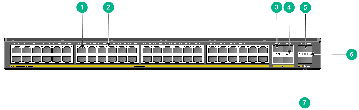
Figure1-1 Front panel
|
(1) 10/100/1000BASE-T autosensing Ethernet port |
|
|
(2) 10/100/1000BASE-T autosensing Ethernet port LED |
|
|
(3) SFP+ port |
(4) SFP+ port LED |
|
(5) QSFP+ port |
(6) QSFP+ port LED |
|
(7) System status LED (SYS) |
|
|
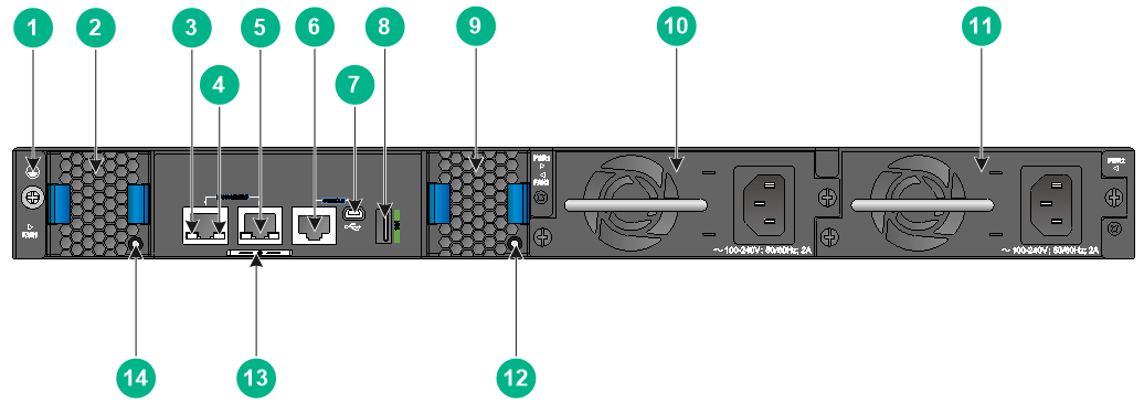
(1) Grounding screw |
(2) Fan tray 1 |
|
(3) LINK LED for the management Ethernet port |
(4) ACT LED for the management Ethernet port |
|
(5) Management Ethernet port |
(6) Console port (CONSOLE) |
|
(7) Mini USB console port |
(8) USB port |
|
(9) Fan tray 2 |
(10) Power module 1 |
|
(11) Power module 2 |
(12) Fan tray 2 status LED |
|
(13) Serial label pull tab |
(14) Fan tray 1 status LED |
The SN serial number and MAC address of the S5850-54QS switch can be found on the serial label pull tab.
The S5850-54QS switch comes with power module slot 1 empty and power module slot 2 installed with a filler panel. You can install one or two power modules for the switch as required. In Figure1-2, two PSR150-A1 AC power modules are installed in the power module slots.
The S5850-54QS switch comes with the two fan tray slots empty. You must install two fan trays of the same model for the switch. In Figure1-2, two LSPM1FANSA-SN fan trays are installed in the fan tray slots.
2 Removable components
Removable power modules
You can install one power module, or two power modules for redundancy on the switch. The switch supports a mixture of an AC power module and a DC power module.
The PSR150-A1 and PSR150-D1 power modules are available for the switch.
Table2-1 Removable power modules
|
Power module |
Specifications |
Reference |
|
PSR150-A1 |
· Rated input voltage range: 100 VAC to 240 VAC @ 50 Hz or 60 Hz · Max input voltage range: 90 VAC to 264 VAC @ 47 Hz to 63 Hz · Max output power: 150 W |
H3C PSR150-A & PSR150-D Series Power Modules User Manual |
|
PSR150-D1 |
· Rated input voltage range: –48 VDC to –60 VDC · Max input voltage range: –36 VDC to –72 VDC · Max output power: 150 W |
Removable fan trays
|
|
CAUTION: You can power on the switch only when the switch has two fan trays of the same model installed. |
The switch supports removable fan trays. The LSPM1FANSA-SN and LSPM1FANSB-SN fan trays are available for the switch.
Table2-2 Removable fan trays
|
Item |
Specifications |
|
LSPM1FANSA-SN fan tray |
|
|
Dimensions |
40 × 40.6 × 105 mm (1.57 × 1.60 × 4.13 in) |
|
Fan speed |
20000 R.P.M |
|
Max airflow |
20 CFM |
|
Airflow direction |
Back to front (from the power module side to the network port side) |
|
Input voltage |
12 V |
|
Maximum power consumption |
9.8 W |
|
Reference |
H3C LSPM1FANSA-SN & LSPM1FANSB-SN Fan Trays User Guide |
|
LSPM1FANSB-SN fan tray |
|
|
Dimensions |
40 × 40.6 × 105 mm (1.57 × 1.60 × 4.13 in) |
|
Fan speed |
20000 R.P.M |
|
Max airflow |
20 CFM |
|
Airflow direction |
Front to back (from the network port side to the power module side) |
|
Input voltage |
12 V |
|
Maximum power consumption |
9.8 W |
|
Reference |
H3C LSPM1FANSA-SN & LSPM1FANSB-SN Fan Trays User Guide |
3 Ports and LEDs
Ports
Console port
The switch has two console ports: a serial console port and a Mini USB console port.
Table3-1 Console port specifications
|
Item |
Console port |
Mini USB console port |
|
Connector type |
RJ-45 |
Mini USB Type B |
|
Compliant standard |
EIA/TIA-232 |
USB 2.0 |
|
Transmission baud rate |
9600 bps (default) to 115200 bps |
|
|
Services |
· Provides connection to an ASCII terminal. · Provides connection to the serial port of a local PC running terminal emulation program. |
Provides connection to the USB port of a local PC running terminal emulation program. |
Management Ethernet port
The switch provides two management Ethernet ports on the rear panel. You can connect this port to a PC or management station for loading and debugging software or remote management.
Table3-2 Management Ethernet port specifications
|
Item |
Specification |
|
Connector type |
RJ-45 |
|
Port transmission rate |
10/100/1000 Mbps, half/full duplex |
|
Transmission medium and max transmission distance |
100 m (328.08 ft) over category-5 twisted pair cable |
|
Functions and services |
Switch software and Boot ROM upgrade, network management |
USB port
The switch has one OHC-compliant USB2.0 port that can upload and download data at a rate up to 480 Mbps. You can use this USB port to access the file system on the flash of the switch, for example, to upload or download application and configuration files.
|
|
NOTE: USB devices from different vendors vary in compatibilities and drivers. H3C does not guarantee the correct operation of USB devices from all vendors on the switch. If a USB device fails to operate on the switch, replace it with one from another vendor. |
SFP+ port
The switch provides four fixed SFP+ ports on the front panel. To connect the peer SFP+ ports over a long distance, use SFP/SFP+ transceiver modules and fibers. To connect the peer SFP+ ports over a short distance, use SFP/SFP+ cables. You can select the GE SFP transceiver modules and cables in Table3-3, 10-GE SFP+ transceiver modules in Table3-4, and 10-GE SFP+ cables in Table3-5 for the SFP+ ports.
Table3-3 GE SFP transceiver modules and cables available for the SFP+ ports
|
GE SFP transceiver module and cable |
Central wavelength (nm) |
Connector |
Cable/Fiber type and diameter (µm) |
Modal bandwidth (MHz × km) |
Max transmission distance |
||
|
SFP copper transceiver module |
|||||||
|
SFP-GE-T |
N/A |
RJ-45 |
Twisted pair cable |
N/A |
100 m (328.08 ft) |
||
|
SFP-GE-T-D |
N/A |
RJ-45 |
Twisted pair cable |
N/A |
100 m (328.08 ft) |
||
|
SFP fiber transceiver module |
|||||||
|
SFP-GE-SX-MM850-A |
850 |
LC |
Multi-mode, 50/125 |
500 |
550 m (1804.46 ft) |
||
|
400 |
500 m (1640.42 ft) |
||||||
|
Multi-mode, 62.5/125 |
200 |
275 m (902.23 ft) |
|||||
|
160 |
220 m (721.78 ft) |
||||||
|
SFP-GE-SX-MM850-D |
850 |
LC |
Multi-mode, 50/125 |
500 |
550 m (1804.46 ft) |
||
|
400 |
500 m (1640.42 ft) |
||||||
|
Multi-mode, 62.5/125 |
200 |
275 m (902.23 ft) |
|||||
|
160 |
220 m (721.78 ft) |
||||||
|
SFP-GE-LX-SM1310-A |
1310 |
LC |
Single-mode, 9/125 |
N/A |
10 km (6.21 miles) |
||
|
Multi-mode, 50/125 |
500 or 400 |
550 m (1804.46 ft) |
|||||
|
Multi-mode, 62.5/125 |
500 |
550 m (1804.46 ft) |
|||||
|
SFP-GE-LX-SM1310-D |
1310 |
LC |
Single-mode, 9/125 |
N/A |
10 km (6.21 miles) |
||
|
SFP-GE-LH40-SM1310 |
1310 |
LC |
Single-mode, 9/125 |
N/A |
40 km (24.86 miles) |
||
|
SFP-GE-LH40-SM1310-D |
1310 |
LC |
Single-mode, 9/125 |
N/A |
40 km (24.86 miles) |
||
|
SFP-GE-LH40-SM1550 |
1550 |
LC |
Single-mode, 9/125 |
N/A |
40 km (24.86 miles) |
||
|
SFP-GE-LH80-SM1550 |
1550 |
LC |
Single-mode, 9/125 |
N/A |
80 km (49.71 miles) |
||
|
SFP-GE-LH80-SM1550-D |
1550 |
LC |
Single-mode, 9/125 |
N/A |
80 km (49.71 miles) |
||
|
SFP-GE-LH100-SM1550 |
1550 |
LC |
Single-mode, 9/125 |
N/A |
100 km (62.14 miles) |
||
|
SFP-GE-LX-SM1310-BIDI |
You must use these two transceiver modules in pairs. |
· TX: 1310 · RX: 1490 |
LC |
Single-mode, 9/125 |
N/A |
10 km (6.21 miles) |
|
|
SFP-GE-LX-SM1490-BIDI |
· TX: 1490 · RX: 1310 |
LC |
Single-mode, 9/125 |
N/A |
10 km (6.21 miles) |
||
Table3-4 10-GE SFP+ transceiver modules available for the SFP+ ports
|
10-GE SFP+ module |
Central
wavelength |
Connector |
Fiber
diameter |
Multimode
fiber modal bandwidth |
Max transmission distance |
|
SFP-XG-SX-MM850-E |
850 |
LC |
Multi-mode, 50/125 |
2000 |
300 m (984.25 ft) |
|
500 |
82 m (269.03 ft) |
||||
|
400 |
66 m (216.54 ft) |
||||
|
Multi-mode, 62.5/125 |
200 |
33 m (108.27 ft) |
|||
|
160 |
26 m (85.30 ft) |
||||
|
SFP-XG-SX-MM850-D |
850 |
LC |
Multi-mode, 50/125 |
2000 |
300 m (984.25 ft) |
|
500 |
82 m (269.03 ft) |
||||
|
400 |
66 m (216.54 ft) |
||||
|
Multi-mode, 62.5/125 |
200 |
33 m (108.27 ft) |
|||
|
160 |
26 m (85.30 ft) |
||||
|
SFP-XG-LX-SM1310-E |
1310 |
LC |
Single-mode, 9/125 |
N/A |
10 km (6.21 miles) |
|
SFP-XG-LX-SM1310-D |
1310 |
LC |
Single-mode, 9/125 |
N/A |
10 km (6.21 miles) |
|
SFP-XG-LH40-SM1550 |
1550 |
LC |
Single-mode, 9/125 |
N/A |
40 km (24.86 miles) |
|
SFP-XG-LH40-SM1550-D |
1550 |
LC |
Single-mode, 9/125 |
N/A |
40 km (24.86 miles) |
|
SFP-XG-LH80-SM1550 |
1550 |
LC |
Single-mode, 9/125 |
N/A |
80 km (49.71 miles) |
|
SFP-XG-LH80-SM1550-D |
1550 |
LC |
Single-mode, 9/125 |
N/A |
80 km (49.71 miles) |
Table3-5 SFP+ cables available for the SFP+ ports
|
Cable description |
Cable length |
|
LSWM1STK |
0.65 m (2.13 ft) |
|
LSWM2STK |
1.2 m (3.94 ft) |
|
LSWM3STK |
3 m (9.84 ft) |
|
LSTM1STK |
5 m (16.40 ft) |
Figure3-1 SFP+ cable

|
(1) Connector |
(2) Pull latch |
|
|
NOTE: · As a best practice, use only H3C SFP/SFP+ transceiver modules and cables for the SFP+ ports. · The H3C SFP/SFP+ transceiver modules and cables available for the SFP+ ports are subject to change over time. For the most recent list of SFP/SFP+ transceiver modules and cables, contact your H3C Support or marketing staff. · For the specifications of H3C SFP/SFP+ transceiver modules and cables, see H3C Transceiver Modules User Guide. |
QSFP+ port
The switch provides QSFP+ ports. You can select the QSFP+ transceiver modules in Table3-6, the QSFP+ cables in Table3-7, and the QSFP+ to SFP+ cables in Table3-8 for the QSFP+ ports.
Table3-6 QSFP+ transceiver modules available for the QSFP+ ports
|
QSFP+ transceiver module |
Central wavelength (nm) |
Connector |
Fiber type and diameter (µm) |
Modal bandwidth (MHz × km) |
Max transmission distance |
|
QSFP-40G-SR4-MM850 |
850 |
MPO |
Multi-mode, 50/125 |
2000 |
100 m (328.08 ft) |
|
4700 |
150 m (492.12 ft) |
||||
|
QSFP-40G-CSR4-MM850 |
850 |
MPO |
Multi-mode, 50/125 |
2000 |
300 m (984.25 ft) |
|
4700 |
400 m (1312.33 ft) |
||||
|
QSFP-40G-LR4-WDM1300 |
Four lanes: · 1271. · 1291. · 1311. · 1331. |
LC |
Single-mode, 9/125 |
N/A |
10 km (6.21 miles) |
Table3-7 QSFP+ cables available for the QSFP+ ports
|
QSFP+ cable |
Max transmission distance |
|
LSWM1QSTK0 |
1 m (3.28 ft) |
|
LSWM1QSTK1 |
3 m (9.84 ft) |
|
LSWM1QSTK2 |
5 m (16.40 ft) |
Table3-8 QSFP+ to SFP+ cables available for the QSFP+ ports
|
QSFP+ to SFP+ cable |
Max transmission distance |
|
LSWM1QSTK3 |
1 m (3.28 ft) |
|
LSWM1QSTK4 |
3 m (9.84 ft) |
|
LSWM1QSTK5 |
5 m (16.40 ft) |
Figure3-2 40G QSFP+ cable

|
(1) Connector |
(2) Pull tab |
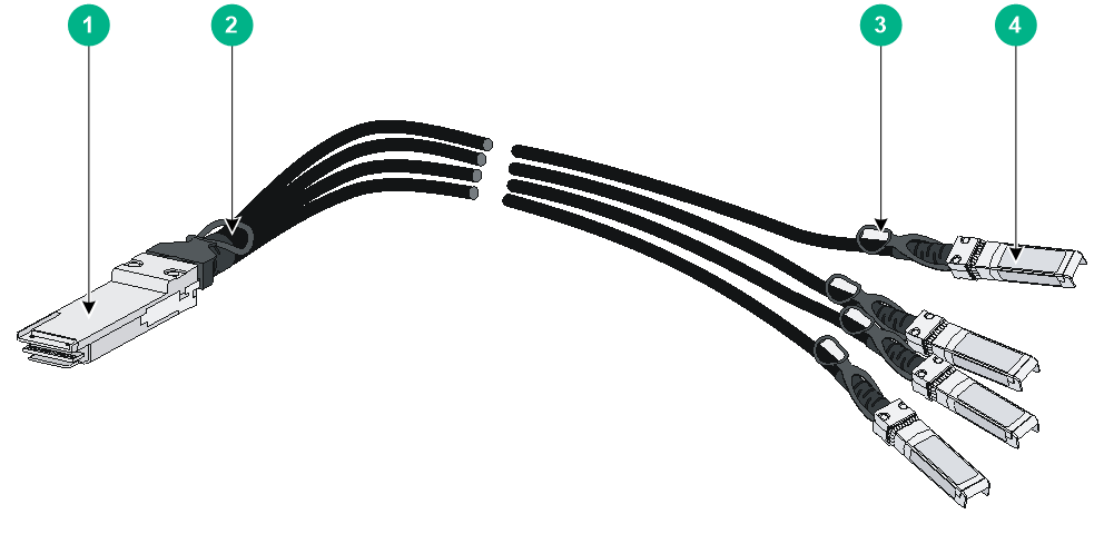
Figure3-3 40G QSFP+ to SFP+ cable
|
(1) QSFP+ module |
(2) QSFP+ side pull tab |
|
(3) SFP+ side pull tab |
(4) SFP+ module |
|
|
NOTE: · As a best practice, use H3C QSFP+ transceiver modules, QSFP+ cables, or QSFP+ to SFP+ cables for the QSFP+ ports on the switch. The H3C QSFP+ transceiver modules, QSFP+ cables, and QSFP+ to SFP+ cables available for the QSFP+ ports are subject to change over time. For the most recent list of QSFP+ transceiver modules, QSFP+ cables, and QSFP+ to SFP+ cables available for the QSFP+ ports, contact H3C Support or marketing staff. · You can use a QSFP-40G-SR4-MM850 or QSFP-40G-CSR4-MM850 transceiver module to connect a QSFP+ port to four SFP+ ports. The QSFP+ transceiver module and SFP+ transceiver modules to be connected must be the same in specifications, including central wavelength and fiber type. |
For more information about H3C QSFP+ transceiver modules, QSFP+ cables, and QSFP+ to SFP+ cables, see H3C Transceiver Modules User Guide.
10/100/1000BASE-T autosensing Ethernet port
Table3-9 10/100/1000BASE-T autosensing Ethernet port specifications
|
Item |
Specification |
|
Connector type |
RJ-45 |
|
Interface attributes |
· 10 Mbps, half/full duplex · 100 Mbps, half/full duplex · 1000 Mbps, full duplex · Auto MDI/MDI-X |
|
Max transmission distance |
100 m (328.08 ft) |
|
Transmission medium |
Category-5 or above twisted pair cable |
|
Standards |
IEEE 802.3i, 802.3u, 802.3ab |
LEDs
System status LED
The system status LED shows the operating state of the switch.
Table3-10 System status LED description
|
LED mark |
Status |
Description |
|
SYS |
Steady green |
The switch is operating correctly. |
|
Flashing green (1 Hz) |
The switch is performing power-on self test (POST). |
|
|
Steady red |
The switch has failed the POST or is faulty. |
|
|
Flashing yellow (1 Hz) |
Some ports have failed to pass POST or are faulty. |
|
|
Off |
The switch is powered off. |
Management Ethernet port LEDs
The switch provides one LINK LED and one ACT LED for each management Ethernet port.
Table3-11 Management Ethernet port LEDs description
|
LED mark |
Status |
Description |
|
LINK |
Off |
The management Ethernet port is not connected. |
|
Steady green |
The management Ethernet port is operating at 10/100/1000 Mbps. |
|
|
ACT |
Off |
The management Ethernet port is not receiving or sending data. |
|
Flashing yellow |
The management Ethernet port is sending or receiving data. |
10/100/1000BASE-T autosensing Ethernet port LED
Table3-12 10/100/1000BASE-T autosensing Ethernet port LED description
|
10/100/1000BASE-T autosensing Ethernet port LED status |
Description |
|
Steady green |
A link is present on the port and the port is operating at 1000 Mbps. |
|
Flashing green |
The port is sending or receiving data at 1000 Mbps |
|
Steady yellow |
A link is present on the port and the port is operating at 10/100 Mbps. |
|
Flashing yellow |
The port is sending or receiving data at 10/100 Mbps |
|
Off |
No link is present on the port. |
SFP+ port LED
Table3-13 SFP+ port LED description
|
SFP+ port LED status |
Description |
|
Steady green |
A link is present on the port and the port is operating at 10 Gbps. |
|
Flashing green |
The port is sending or receiving data at 10 Gbps. |
|
Steady yellow |
A link is present on the port and the port is operating at 1 Gbps. |
|
Flashing yellow |
The port is sending or receiving data at 1 Gbps. |
|
Flashing yellow (3 Hz) |
The port has failed POST. |
|
Off |
No link is present on the port. |
QSFP+ port LED
Table3-14 QSFP+ port LED description
|
LED status |
Description |
|
Steady green |
A link is present on the port and the port is operating at 40 Gbps. |
|
Flashing green |
The port is sending or receiving data at 40 Gbps. |
|
Steady yellow |
A link is present on the port and the port is operating at 10 Gbps. |
|
Flashing yellow |
The port is sending or receiving data at 10 Gbps. |
|
Off |
No transceiver module or cable has been installed or no link is present on the port. |
Fan tray status LED on the fan tray
The LSPM1FANSA-SN and LSPM1FANSB-SN fan trays each have a fan tray status LED to indicate their operating status.
Table3-15 Fan tray status LED description
|
LED mark |
Status |
Description |
|
FAN |
Steady yellow |
The fan tray is operating correctly. |
|
Flashing yellow (1Hz) |
The fan tray is faulty. |
|
|
Off |
The fan tray has not been installed or has no power input. |
4 Cooling system
To dissipate heat timely and ensure system stability, the switch uses high-performance cooling system. Consider the site ventilation design when you plan the installation site for the switch.
The switch uses hot-swappable fan trays. You can provide airflow from the power module side to the port side or from the port side to the power module side for the switch by using different fan trays. For heat dissipation, install two fan trays of the same model for the switch.
Table4-1 Cooling system
|
Switch model |
Available fan tray |
Airflow direction |
|
S5850-54QS |
LSPM1FANSA-SN |
From the power module side to the port side |
|
LSPM1FANSB-SN |
From the port side to the power module side |
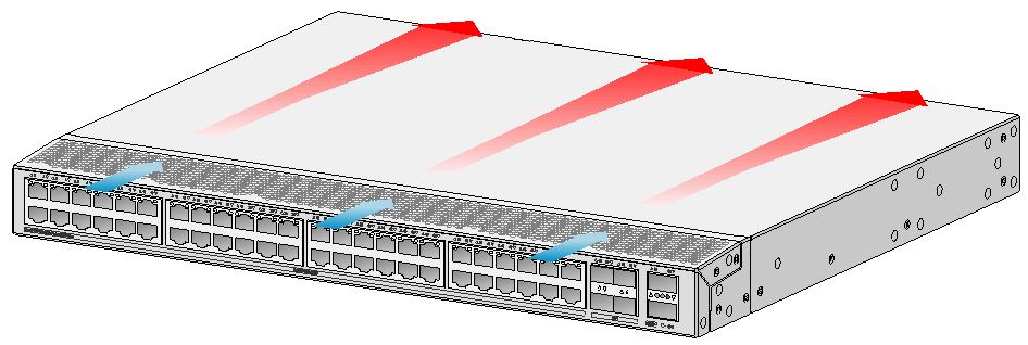
Figure4-1 Airflow from the power module side to the port side (with LSPM1FANSA-SN fan trays)
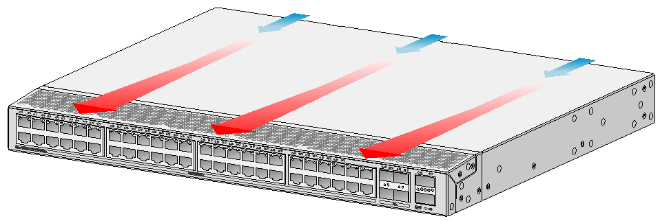
Figure4-2 Airflow from the port side to the power module side (with LSPM1FANSB-SN fan trays)