- Table of Contents
-
- 16-Security Configuration Guide
- 00-Preface
- 01-ACL configuration
- 02-APR configuration
- 03-ARP attack protection configuration
- 04-ASPF configuration
- 05-IP source guard configuration
- 06-IPsec configuration
- 07-ND attack defense configuration
- 08-Password control configuration
- 09-PKI configuration
- 10-SSH configuration
- 11-SSL configuration
- 12-SSL VPN configuration
- 13-URL filtering configuration
- 14-User profile configuration
- 15-Bandwidth management configuration
- 16-Public key management
- 17-Attack detection and prevention configuration
- 18-Session management
- 19-Connection limit configuration
- 20-Crypto engine configuration
- 21-Time range configuration
- 22-Protocol packet rate limit configuration
- 23-DPI engine configuration
- Related Documents
-
| Title | Size | Download |
|---|---|---|
| 03-ARP attack protection configuration | 281.01 KB |
Contents
Configuring ARP attack protection
ARP attack protection tasks at a glance
Configuring unresolvable IP attack protection
About unresolvable IP attack protection
Configuring ARP source suppression
Configuring ARP blackhole routing
Display and maintenance commands for unresolvable IP attack protection
Configuring source MAC-based ARP attack detection
About source MAC-based ARP attack detection
Display and maintenance commands for source MAC-based ARP attack detection
Example: Configuring source MAC-based ARP attack detection
Configuring ARP packet source MAC consistency check
Configuring ARP active acknowledgement
Example: Configuring authorized ARP on a DHCP server
Example: Configuring authorized ARP on a DHCP relay agent
Configuring ARP attack detection
Configuring user validity check
Configuring ARP packet validity check
Configuring ARP restricted forwarding
Display and maintenance commands for ARP attack detection
Example: Configuring user validity check
Configuring ARP scanning and fixed ARP
Configuring ARP gateway protection
Example: Configuring ARP gateway protection
Example: Configuring ARP filtering
Configuring ARP attack protection
About ARP attack protection
The device can provide multiple features to detect and prevent ARP attacks and viruses in the LAN. An attacker can exploit ARP vulnerabilities to attack network devices in the following ways:
· Sends a large number of unresolvable IP packets to have the receiving device busy with resolving IP addresses until its CPU is overloaded. Unresolvable IP packets refer to IP packets for which ARP cannot find corresponding MAC addresses.
· Sends a large number of ARP packets to overload the CPU of the receiving device.
· Acts as a trusted user or gateway to send ARP packets so the receiving devices obtain incorrect ARP entries.
ARP attack protection tasks at a glance
All ARP attack protection tasks are optional.
· Preventing flood attacks
¡ Configuring unresolvable IP attack protection
¡ Configuring source MAC-based ARP attack detection
· Preventing user and gateway spoofing attacks
¡ Configuring ARP packet source MAC consistency check
¡ Configuring ARP active acknowledgement
¡ Configuring ARP attack detection
¡ Configuring ARP scanning and fixed ARP
¡ Configuring ARP gateway protection
Configuring unresolvable IP attack protection
About unresolvable IP attack protection
If a device receives a large number of unresolvable IP packets from a host, the following situations can occur:
· The device sends a large number of ARP requests, overloading the target subnets.
· The device keeps trying to resolve the destination IP addresses, overloading its CPU.
To protect the device from such IP attacks, you can configure the following features:
· ARP source suppression—Stops resolving packets from an IP address if the number of unresolvable IP packets from the IP address exceeds the upper limit within 5 seconds. The device continues ARP resolution when the interval elapses. This feature is applicable if the attack packets have the same source addresses.
· ARP blackhole routing—Creates a blackhole route destined for an unresolved IP address. The device drops all matching packets until the blackhole route is deleted. A blackhole route is deleted when its aging timer is reached or the route becomes reachable.
After a blackhole route is created for an unresolved IP address, the device immediately starts the first ARP blackhole route probe by sending an ARP request. If the resolution fails, the device continues probing according to the probe settings. If the IP address resolution succeeds in a probe, the device converts the blackhole route to a normal route. If an ARP blackhole route ages out before the device finishes all probes, the device deletes the blackhole route and does not perform the remaining probes.
This feature is applicable regardless of whether the attack packets have the same source addresses.
Configuring ARP source suppression
1. Enter system view.
system-view
2. Enable ARP source suppression.
arp source-suppression enable
By default, ARP source suppression is disabled.
3. Set the maximum number of unresolvable packets that the device can process per source IP address within 5 seconds.
arp source-suppression limit limit-value
By default, the maximum number is 10.
Configuring ARP blackhole routing
Restrictions and guidelines
Set the ARP blackhole route probe count to a big value, for example, 25. If the device fails to reach the destination IP address temporarily and the probe count is too small, all probes might finish before the problem is resolved. As a result, non-attack packets will be dropped. This setting can avoid such situation.
Procedure
1. Enter system view.
system-view
2. Enable ARP blackhole routing.
arp resolving-route enable
By default, ARP blackhole routing is enabled.
3. (Optional.) Set the number of ARP blackhole route probes for each unresolved IP address.
arp resolving-route probe-count count
The default setting is three probes.
4. (Optional.) Set the interval at which the device probes ARP blackhole routes.
arp resolving-route probe-interval interval
The default setting is 1 second.
Display and maintenance commands for unresolvable IP attack protection
Execute display commands in any view.
|
Task |
Command |
|
Display ARP source suppression configuration information. |
display arp source-suppression |
Configuring source MAC-based ARP attack detection
About source MAC-based ARP attack detection
This feature checks the number of ARP packets delivered to the CPU. If the number of packets from the same MAC address within 5 seconds exceeds a threshold, the device generates an ARP attack entry for the MAC address. If the ARP logging feature is enabled, the device handles the attack by using either of the following methods before the ARP attack entry ages out:
· Monitor—Only generates log messages.
· Filter—Generates log messages and filters out subsequent ARP packets from the MAC address.
To enable the ARP logging feature, use the arp check log enable command. For information about the ARP logging feature, see ARP configuration in Network Connectivity Configuration Guide.
When an ARP attack entry ages out, ARP packets sourced from the MAC address in the entry can be processed correctly.
Restrictions and guidelines
When you change the handling method from monitor to filter, the configuration takes effect immediately. When you change the handling method from filter to monitor, the device continues filtering packets that match existing attack entries.
You can exclude the MAC addresses of some gateways and servers from this detection. This feature does not inspect ARP packets from those devices even if they are attackers.
Procedure
1. Enter system view.
system-view
2. Enable source MAC-based ARP attack detection and specify the handling method.
arp source-mac { filter | monitor }
By default, this feature is disabled.
3. Set the threshold.
arp source-mac threshold threshold-value
By default, the threshold for source MAC-based ARP attack detection is 30.
4. Set the aging timer for ARP attack entries.
arp source-mac aging-time time
By default, the lifetime is 300 seconds.
5. (Optional.) Exclude specific MAC addresses from this detection.
arp source-mac exclude-mac mac-address&<1-n>
By default, no MAC address is excluded.
Display and maintenance commands for source MAC-based ARP attack detection
Execute display commands in any view.
|
|
IMPORTANT: The WX1800H series, WX2500H series and WX3000H series access controllers do not support parameters or commands that are available only in IRF mode. |
|
Task |
Command |
|
Display ARP attack entries detected by source MAC-based ARP attack detection. |
In standalone mode: display arp source-mac [ interface interface-type interface-number ] In IRF mode: display arp source-mac { interface interface-type interface-number | slot slot-number } |
Example: Configuring source MAC-based ARP attack detection
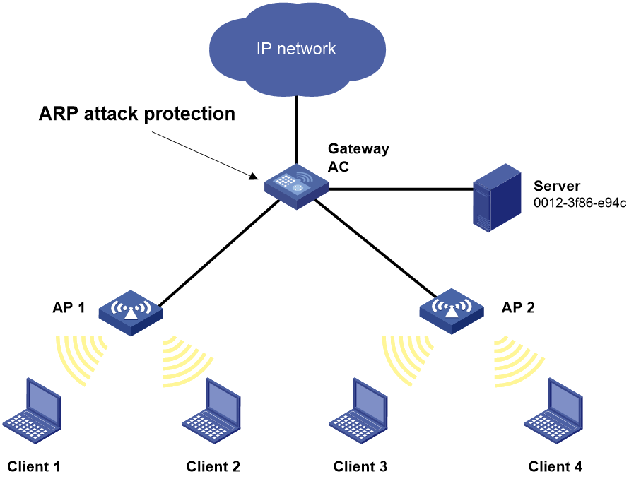
Network configuration
As shown in Figure 1, the hosts access the Internet through a gateway (AC). If malicious users send a large number of ARP requests to the gateway, the gateway might crash and cannot process requests from the clients. To solve this problem, configure source MAC-based ARP attack detection on the gateway.
Procedure
# Enable source MAC-based ARP attack detection, and specify the handling method as filter.
<AC> system-view
[AC] arp source-mac filter
# Set the threshold to 30.
[AC] arp source-mac threshold 30
# Set the lifetime for ARP attack entries to 60 seconds.
[AC] arp source-mac aging-time 60
# Exclude MAC address 0012-3f86-e94c from this detection.
[AC] arp source-mac exclude-mac 0012-3f86-e94c
Configuring ARP packet source MAC consistency check
About this task
This feature enables a gateway to filter out ARP packets whose source MAC address in the Ethernet header is different from the sender MAC address in the message body. This feature allows the gateway to learn correct ARP entries.
Procedure
1. Enter system view.
system-view
2. Enable ARP packet source MAC address consistency check.
arp valid-check enable
By default, ARP packet source MAC address consistency check is disabled.
Configuring ARP active acknowledgement
About this task
Use the ARP active acknowledgement feature on gateways to prevent user spoofing.
This feature enables the device to perform active acknowledgement before creating an ARP entry.
· Upon receiving an ARP request that requests the MAC address of the device, the device sends an ARP reply. Then, it sends an ARP request for the sender IP address in the received ARP request to determine whether to create an ARP entry for the sender IP address.
¡ If the device receives an ARP reply within the probe interval, it creates the ARP entry.
¡ If the device does not receive an ARP reply within the probe interval, it does not create the ARP entry.
· Upon receiving an ARP reply, the device examines whether it was the reply to the request that the device has sent.
¡ If it was, the device creates an ARP entry for the sender IP address in the ARP reply.
¡ If it was not, the device sends an ARP request for the sender IP address to determine whether to create an ARP entry for the sender IP address.
- If the device receives an ARP reply within the probe interval, it creates the ARP entry.
- If the device does not receive an ARP reply within the probe interval, it does not create the ARP entry.
To improve validity and reliability of ARP entries, you can enable ARP active acknowledgement in strict mode. In this mode, the device creates ARP entries only for the IP addresses that the device actively initiates the ARP resolution.
Procedure
1. Enter system view.
system-view
2. Enable ARP active acknowledgement.
arp active-ack [ strict ] enable
By default, ARP active acknowledgement is disabled.
For ARP active acknowledgement to take effect in strict mode, make sure ARP blackhole routing is enabled.
Configuring authorized ARP
About authorized ARP
Authorized ARP entries are generated based on the DHCP clients' address leases on the DHCP server or dynamic client entries on the DHCP relay agent. For more information about DHCP server and DHCP relay agent, see Network Connectivity Configuration Guide.
Use this feature to prevent user spoofing and to allow only authorized clients to access network resources.
Procedure
1. Enter system view.
system-view
2. Enter interface view.
interface interface-type interface-number
Supported interface types include Layer 3 Ethernet interface, Layer 3 Ethernet subinterface, and VLAN interface.
3. Enable authorized ARP on the interface.
arp authorized enable
By default, authorized ARP is disabled.
Example: Configuring authorized ARP on a DHCP server
Network configuration
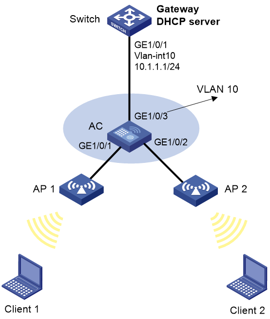
As shown in Figure 2, the client obtains an IPv4 address through DHCP. Configure authorized ARP on VLAN-interface 10 of the AC (a DHCP server) to ensure user validity.

Procedure
# Configure DHCP.
<AC> system-view
[AC] dhcp enable
[AC] dhcp server ip-pool 1
[AC-dhcp-pool-1] network 10.1.1.0 mask 255.255.255.0
[AC-dhcp-pool-1] quit
# Specify the IP address for VLAN-interface 10.
[AC] vlan 10
[AC-vlan10] quit
[AC] interface vlan-interface 10
[AC-Vlan-interface10] ip address 10.1.1.1 24
# Enable authorized ARP on VLAN-interface 10.
[AC-Vlan-interface10] arp authorized enable
[AC-Vlan-interface10] quit
Verifying the configuration
# After the Display authorized ARP entry information on the AC.
[AC] display arp
Type: S-Static D-Dynamic O-Openflow R-Rule I-Invalid
IP Address MAC Address SVLAN/VSI Interface/Link ID Aging Type
10.1.1.2 0012-3f86-e94c -- WLAN-BSS1/0/85703 20 D
The output shows that IP address 10.1.1.2 has been assigned to the client.
The client must use the IP address and MAC address in the authorized ARP entry to communicate with AC. Otherwise, the communication fails. Thus user validity is ensured.
Example: Configuring authorized ARP on a DHCP relay agent
Network configuration
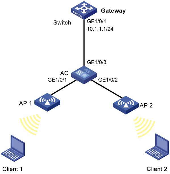
As shown in Figure 3, the switch acts as the DHCP server and assigns IP addresses on subnet 10.10.1.0/24 to the DHCP client. The AC acts as the DHCP relay agent. Configure authorized ARP on VLAN-interface 20 of the AC to ensure user validity.

Procedure
1. Configure the switch:
# Specify the IP address for VLAN-interface 10.
<Switch> system-view
[Switch] interface vlan-interface 10
[Switch-Vlan-interface10] ip address 10.1.1.1 24
[Switch-Vlan-interface10] quit
# Configure DHCP.
[Switch] dhcp enable
[Switch] dhcp server ip-pool 1
[Switch-dhcp-pool-1] network 10.10.1.0 mask 255.255.255.0
[Switch-dhcp-pool-1] gateway-list 10.10.1.1
[Switch-dhcp-pool-1] quit
[Switch] ip route-static 10.10.1.0 24 10.1.1.2
2. Configure the AC:
# Enable DHCP.
<AC> system-view
[AC] dhcp enable
# Specify the IP addresses of VLAN-interface 10 and VLAN-interface 20.
[AC] interface vlan-interface 10
[AC-Vlan-interface10] ip address 10.1.1.2 24
[AC-Vlan-interface10] quit
[AC] interface vlan-interface 20
[AC-Vlan-interface20] ip address 10.10.1.1 24
# Enable DHCP relay agent on VLAN-interface 20.
[AC-Vlan-interface20] dhcp select relay
# Specify DHCP server address 10.1.1.1 on the DHCP relay agent.
[AC-Vlan-interface20] dhcp relay server-address 10.1.1.1
# Enable authorized ARP.
[AC-Vlan-interface20] arp authorized enable
[AC-Vlan-interface20] quit
# Enable the recording of relay entries on the relay agent.
[AC] dhcp relay client-information record
Verifying the configuration
# Display authorized ARP information on the AC.
[AC] display arp
Type: S-Static D-Dynamic O-Openflow R-Rule I-Invalid
IP Address MAC Address SVLAN/VSI Interface/Link ID Aging Type
10.10.1.2 0012-3f86-e94c -- WLAN-BSS1/0/85703 20 D
The output shows that the AC assigned the IP address 10.10.1.2 to the client.
The client must use the IP address and MAC address in the authorized ARP entry to communicate with the AC. Otherwise, the communication fails. Thus the user validity is ensured.
Configuring ARP attack detection
About ARP attack detection
ARP attack detection enables access devices to block ARP packets from unauthorized clients to prevent user spoofing and gateway spoofing attacks.
ARP attack detection provides the following features:
· User validity check.
· ARP packet validity check.
· ARP restricted forwarding.
· ARP attack detection logging.
If both ARP packet validity check and user validity check are enabled, the former one applies first, and then the latter applies.
Configuring user validity check
About this task
User validity check does not check ARP packets received on ARP trusted interfaces. This feature compares the sender IP and sender MAC in the ARP packet received on an ARP untrusted interface with the matching criteria in the following order:
1. User validity check rules.
¡ If a match is found, the device processes the ARP packet according to the rule.
¡ If no match is found or no user validity check rule is configured, proceeds to step 2.
2. 802.1X security entries and DHCP snooping entries.
¡ If a match is found, the device forwards the ARP packet.
¡ If no match is found, the device discards the ARP packet.
DHCP snooping entries are automatically generated by DHCP snooping. For more information, see DHCP snooping configuration in Network Connectivity Configuration Guide.
802.1X security entries record the IP-to-MAC mappings for 802.1X clients. After a client passes 802.1X authentication and uploads its IP address to an ARP attack detection enabled device, the device automatically generates an 802.1X security entry. The 802.1X client must be enabled to upload its IP address to the device. For more information, see 802.1X configuration in User Access and Authentication Configuration Guide.
Restrictions and guidelines
When you configure user validity check, make sure one or more of the following items are configured:
· User validity check rules.
· DHCP snooping.
· 802.1X.
If none of the items is configured, all incoming ARP packets on ARP untrusted interfaces are forwarded.
Procedure
1. Enter system view.
system-view
2. (Optional.) Configure a user validity check rule.
arp detection rule rule-id { deny | permit } ip { ip-address [ mask ] | any } mac { mac-address [ mask ] | any } [ vlan vlan-id ]
By default, no user validity check rules are configured.
3. Enter VLAN view.
vlan vlan-id
4. Enable ARP attack detection.
arp detection enable
By default, ARP attack detection is disabled. The device does not perform user validity check.
5. (Optional.) Configure an interface that does not require ARP user validity check as a trusted interface.
a. Return to system view.
quit
b. Enter interface view.
interface interface-type interface-number
Supported interface types include Layer 2 Ethernet interface and Layer 2 aggregate interface.
c. Configure the interface as a trusted interface excluded from ARP attack detection.
By default, an interface is untrusted.
Configuring ARP packet validity check
About this task
ARP packet validity check does not check ARP packets received on ARP trusted interfaces. To check ARP packets received on untrusted interfaces, you can specify the following objects to be checked:
· src-mac—Checks whether the sender MAC address in the message body is identical to the source MAC address in the Ethernet header. If they are identical, the packet is forwarded. Otherwise, the packet is discarded.
· dst-mac—Checks the target MAC address of ARP replies. If the target MAC address is all-zero, all-one, or inconsistent with the destination MAC address in the Ethernet header, the packet is considered invalid and discarded.
· ip—Checks the sender and target IP addresses of ARP replies, and the sender IP address of ARP requests. All-one or multicast IP addresses are considered invalid and the corresponding packets are discarded.
Prerequisites
Before you configure ARP packet validity check, you must first configure user validity check. For more information about user validity check configuration, see "Configuring user validity check."
Procedure
1. Enter system view.
system-view
2. Enter VLAN view.
vlan vlan-id
3. Enable ARP attack detection.
arp detection enable
By default, ARP attack detection is disabled.
4. Enable ARP packet validity check.
a. Return to system view.
quit
b. Enable ARP packet validity check and specify the objects to be checked.
arp detection validate { dst-mac | ip | src-mac } *
By default, ARP packet validity check is disabled.
5. (Optional.) Configure the interface that does not require ARP packet validity check as a trusted interface.
a. Enter interface view.
interface interface-type interface-number
Supported interface types include Layer 2 Ethernet interface and Layer 2 aggregate interface.
b. Configure the interface as a trusted interface excluded from ARP attack detection.
arp detection trust
By default, an interface is untrusted.
Configuring ARP restricted forwarding
About this task
ARP restricted forwarding does not take effect on ARP packets received on ARP trusted interfaces and forwards the ARP packets correctly. This feature controls the forwarding of ARP packets that are received on untrusted interfaces and have passed user validity check as follows:
· If the packets are ARP requests, they are forwarded through the trusted interface.
· If the packets are ARP replies, they are forwarded according to their destination MAC address. If no match is found in the MAC address table, they are forwarded through the trusted interface.
Restrictions and guidelines
ARP restricted forwarding does not apply to ARP packets that use multiport destination MAC addresses.
Prerequisites
Configure user validity check before you configure ARP restricted forwarding. For information about user validity check configuration, see "Configuring user validity check."
Procedure
1. Enter system view.
system-view
2. Enter VLAN view.
vlan vlan-id
3. Enable ARP restricted forwarding.
arp restricted-forwarding enable
By default, ARP restricted forwarding is disabled.
Display and maintenance commands for ARP attack detection
Execute display commands in any view and reset commands in user view.
|
Task |
Command |
|
Display the VLANs enabled with ARP attack detection. |
display arp detection |
|
Display statistics for packets dropped by ARP attack detection. |
display arp detection statistics [ interface interface-type interface-number ] |
|
Clear statistics for packets dropped by ARP attack detection. |
reset arp detection statistics [ interface interface-type interface-number ] |
Example: Configuring user validity check
Network configuration
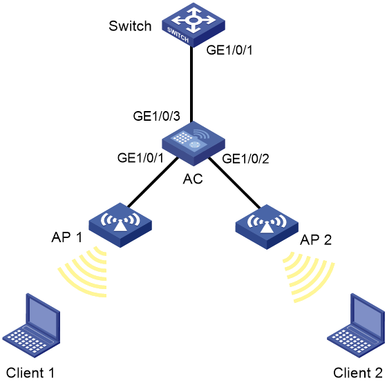
As shown in Figure 4, the switch acts as the DHCP server and the AC supports 802.1X. Enable ARP attack detection in VLAN 10 to perform user validity check based on 802.1X security entries for the clients.
Client 1 and Client 2 are 802.1X local users and supports uploading IP addresses.
Procedure
1. Add all interfaces on the AC to VLAN 10, and specify the IP address of VLAN-interface 10 on the switch. (Details not shown.)
2. Configure the DHCP server on the switch, and configure DHCP address pool 0.
<Switch> system-view
[Switch] dhcp enable
[Switch] dhcp server ip-pool 0
[Switch-dhcp-pool-0] network 10.1.1.0 mask 255.255.255.0
3. Configure Client 1 and Client 2 as 802.1X clients and configure them to upload IP addresses for ARP attack detection. (Details not shown.)
4. Configure the AC:
# Configure the AC to perform EAP termination and use CHAP to communicate with the RADIUS server.
[AC] dot1x authentication-method chap
# Create an ISP domain named local and enter ISP domain view.
# Configure the ISP domain to use local authentication, local authorization, and local accounting for LAN clients.
[AC-isp-local] authentication lan-access local
[AC-isp-local] authorization lan-access local
[AC-isp-local] accounting lan-access local
[AC-isp-local] quit
# Create a service template named wlas_local_chap and enter its view.
[AC] wlan service-template wlas_local_chap
[AC-wlan-st-wlas_local_chap] client-security authentication-mode dot1x
# Specify ISP domain local for the service template.
[AC-wlan-st-wlas_local_chap] dot1x domain local
# Set the SSID to wlas_local_chap.
[AC-wlan-st-wlas_local_chap] ssid wlas_local_chap
# Enable the service template.
[AC-wlan-st-wlas_local_chap] service-template enable
[AC-wlan-st-wlas_local_chap] quit
# Create AP ap1, and specify the AP model and serial ID.
[AC] wlan ap ap1 model WA4320i-ACN
[AC-wlan-ap-ap 1] serial-id 210235A1BSC123000050
[AC-wlan-ap-ap 1] quit
# Configure channel 149 as the working channel for radio 1 of the AP, and enable radio 1.
[AC-wlan-ap-ap1] radio 1
[AC-wlan-ap-ap1-radio-1] channel 149
[AC-wlan-ap-ap1-radio-1] radio enable
# Bind service template wlas_local_chap to radio 1.
[AC-wlan-ap-ap1-radio-1] service-template wlas_local_chap
[AC-wlan-ap-ap1-radio-1] quit
[AC-wlan-ap-ap1] quit
# Add a network access user named test.
[AC] local-user test class network
[AC-luser-network-test] service-type lan-access
[AC-luser-network-test] password simple test
[AC-luser-network-test] quit
# Enable ARP attack detection for VLAN 10 to check user validity based on 802.1X entries.
[AC] vlan 10
[AC-vlan10] arp detection enable
# Configure the upstream interface as an ARP trusted interface. By default, an interface is an untrusted interface.
[AC-vlan10] interface gigabitethernet 1/0/3
[AC-GigabitEthernet1/0/3] arp detection trust
[AC-GigabitEthernet1/0/3] quit
Verifying the configuration
# Verify that ARP packets received on interfaces GigabitEthernet 1/0/1 and GigabitEthernet 1/0/2 are checked against 802.1X entries.
Configuring ARP scanning and fixed ARP
About this task
ARP scanning is typically used together with the fixed ARP feature in small-scale and stable networks.
ARP scanning automatically creates ARP entries for devices in an address range. The device performs ARP scanning in the following steps:
1. Sends ARP requests for each IP address in the address range.
2. Obtains their MAC addresses through received ARP replies.
3. Creates dynamic ARP entries.
Fixed ARP converts existing dynamic ARP entries (including those generated through ARP scanning) to static ARP entries. These static ARP entries are of the same attributes as the ARP entries that are manually configured. This feature prevents ARP entries from being modified by attackers.
Restrictions and guidelines
IP addresses in existing ARP entries are not scanned.
ARP scanning will take some time. To stop an ongoing scan, press Ctrl + C. Dynamic ARP entries are created based on ARP replies received before the scan is terminated.
Due to the limit on the total number of static ARP entries, some dynamic ARP entries might fail the conversion.
The arp fixup command is a one-time operation. You can use this command again to convert the dynamic ARP entries learned later to static.
To delete a static ARP entry converted from a dynamic one, use the undo arp ip-address command. You can also use the reset arp all command to delete all ARP entries or the reset arp static command to delete all static ARP entries.
Procedure
1. Enter system view.
system-view
2. Enter interface view.
interface interface-type interface-number
3. Trigger an ARP scanning.
arp scan [ start-ip-address to end-ip-address ]
4. Return to system view.
quit
5. Convert existing dynamic ARP entries to static ARP entries.
arp fixup
Configuring ARP gateway protection
About ARP gateway protection
Configure this feature on interfaces not connected with a gateway to prevent gateway spoofing attacks.
When such an interface receives an ARP packet, it checks whether the sender IP address in the packet is consistent with that of any protected gateway. If yes, it discards the packet. If not, it handles the packet correctly.
Restrictions and guidelines
You can enable ARP gateway protection for a maximum of eight gateways on an interface.
Do not configure both the arp filter source and arp filter binding commands on an interface.
If ARP gateway protection works with ARP attack detection and ARP fast-reply, ARP gateway protection applies first.
Procedure
1. Enter system view.
system-view
2. Enter interface view.
interface interface-type interface-number
Supported interface types include Layer 2 Ethernet interface and Layer 2 aggregate interface.
3. Enable ARP gateway protection for the specified gateway.
arp filter source ip-address
By default, ARP gateway protection is disabled.
Example: Configuring ARP gateway protection
Network configuration
As shown in Figure 5, Client 2 launches gateway spoofing attacks to the AC. As a result, traffic that the AC intends to send to the switch is sent to Client 2.
Configure Switch B to block such attacks.
Procedure
# Configure ARP gateway protection on the AC.
<AC> system-view
[AC] interface gigabitethernet 1/0/1
[AC-GigabitEthernet1/0/1] arp filter source 10.1.1.1
[AC-GigabitEthernet1/0/1] quit
[AC] interface gigabitethernet 1/0/2
[AC-GigabitEthernet1/0/2] arp filter source 10.1.1.1
Verifying the configuration
Verify that GigabitEthernet 1/0/1 and GigabitEthernet 1/0/2 discard the incoming ARP packets whose sender IP address is the IP address of the gateway.
Configuring ARP filtering
ARP filtering
The ARP filtering feature can prevent gateway spoofing and user spoofing attacks.
An interface enabled with this feature checks the sender IP and MAC addresses in a received ARP packet against permitted entries. If a match is found, the packet is handled correctly. If not, the packet is discarded.
Restrictions and guidelines
You can configure a maximum of eight permitted entries on an interface.
Do not configure both the arp filter source and arp filter binding commands on an interface.
If ARP filtering works with ARP attack detection and ARP fast-reply, ARP filtering applies first.
Procedure
1. Enter system view.
system-view
2. Enter interface view.
interface interface-type interface-number
Supported interface types include Ethernet interface and Layer 2 aggregate interface.
3. Enable ARP filtering and configure a permitted entry.
arp filter binding ip-address mac-address
By default, ARP filtering is disabled.
Example: Configuring ARP filtering
Network configuration
As shown in Figure 6, the IP and MAC addresses of Client 1 are 10.1.1.2 and 000f-e349-1233, respectively. The IP and MAC addresses of Client 2 are 10.1.1.3 and 000f-e349-1234, respectively.
Configure ARP filtering on GigabitEthernet 1/0/1 and GigabitEthernet 1/0/2 of the AC to permit ARP packets from only Client 1 and Client 2.
Procedure
# Configure ARP filtering on the AC.
<AC> system-view
[AC] interface gigabitethernet 1/0/1
[AC-GigabitEthernet1/0/1] arp filter binding 10.1.1.2 000f-e349-1233
[AC-GigabitEthernet1/0/1] quit
[AC] interface gigabitethernet 1/0/2
[AC-GigabitEthernet1/0/2] arp filter binding 10.1.1.3 000f-e349-1234
Verifying the configuration
# Verify that GigabitEthernet 1/0/1 permits ARP packets from Client 1 and discards other ARP packets.
# Verify that GigabitEthernet 1/0/2 permits ARP packets from Client 2 and discards other ARP packets.