- Table of Contents
-
- 12-WLAN Advanced Features Configuration Guide
- 00-Preface
- 01-Bonjour gateway configuration
- 02-Hotspot 2.0 configuration
- 03-WLAN mesh configuration
- 04-Wireless location configuration
- 05-WLAN process maintenance configuration
- 06-WLAN fast forwarding configuration
- 07-WLAN optimization configuration
- 08-AC hierarchy configuration
- 09-WSA configuration
- 10-WLAN probe configuration
- Related Documents
-
| Title | Size | Download |
|---|---|---|
| 03-WLAN mesh configuration | 536.79 KB |
Contents
Neighbor discovery and mesh link establishment
Mesh peer blacklist or whitelist
Restrictions and guidelines: WLAN mesh configuration
Binding a mesh profile to a radio
Binding a mesh policy to a radio
Disabling an MPP from sending probe requests
Enabling MPPs associated with the same AC to become mesh peers
Configuring the mesh peer blacklist or whitelist
Setting access port attributes for a mesh interface
Setting trunk port attributes for a mesh interface
Setting hybrid port attributes for a mesh interface
Binding a mesh interface to a radio
Display and maintenance commands for WLAN mesh
WLAN mesh configuration examples
Example: Configuring WLAN mesh
Example: Configuring VLAN settings for a WLAN mesh network
Configuring WLAN mesh
About WLAN mesh
WLAN mesh allows APs to be wirelessly connected. The APs on a WLAN mesh network can be connected directly or over multiple hops. When one AP fails, the remaining APs can still communicate with each other.
Benefits
WLAN mesh provides the following benefits:
· Low cost, high performance, and easy deployment.
· High expansibility without wires.
· Same good user experience as traditional WLANs.
WLAN mesh network
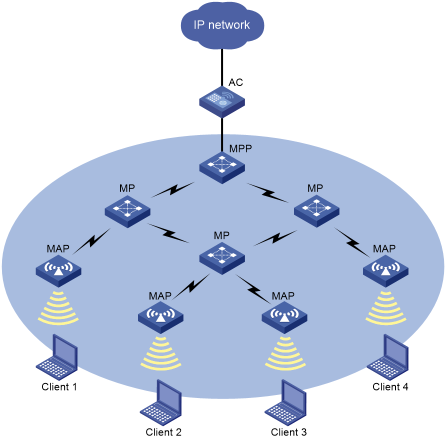
Figure 1 shows a WLAN mesh network.
APs on a WLAN mesh network are mesh points (MPs). MPs play the following roles:
· Single-purpose MP—Provides only mesh services.
· Mesh access point (MAP)—Provides both mesh and access services.
· Mesh portal point (MPP)—Provides a wired connection to a wired network.
Figure 1 WLAN mesh network diagram
Mesh profile
A mesh profile is a set of mesh protocol processing capabilities for an AP to operate on a mesh network. A mesh profile contains the following attributes:
· Mesh ID—Identifies a mesh network.
· Mesh security—Contains settings for neighbor authentication, including an authentication and key management mode, and a preshared key.
· Keepalive interval—Specifies the interval for sending keepalive packets over a mesh link. The MP with a higher MAC address sends keepalive packets at the keepalive interval to the peer end. The sending MP disconnects the mesh link if it has not received a reply before three consecutive keepalive intervals expire. The receiving MP disconnects the mesh link if it has not received keepalive packets before three consecutive keepalive intervals expire. For correct link status detection, the keepalive interval at the sending end must be equal to or less than three times the keepalive interval at the receiving end.
To form a mesh network, APs must have the same mesh ID and mesh security settings.
Neighbor discovery and mesh link establishment
MPs must operate at the same radio mode and on the same channel to discover each other. MPs can establish a mesh link after they discover each other and establish a peer relationship.
The following are the available discovery methods:
· Active scanning—The MP sends Probe Request frames to discover neighbors and establish peer relationships.
· Passive scanning—The MP listens to Beacon frames to collect information about other MPs. If there are neighbors, the AP sends Probe Request frames to request establishing a peer relationship.
This section uses active scanning to describe the neighbor discovery and mesh link establishment process.
As shown in Figure 2, MPs attempt to establish peer relationships by exchanging their mesh profiles in Probe Request and Probe Response frames.
One MP adds another MP as a mesh peer if the following conditions are met:
· The MPs' mesh profiles match.
· The Accepting Peer Links bit in the received request or response is set.
The MP peers attempt to establish a mesh link by sending a Link Open request to each other. The mesh link is established after the MP peers acknowledge the Link Open request received from each other.
Figure 2 Neighbor discovery and mesh link establishment on a WLAN mesh network

Fit APs must obtain a mesh profile from the AC before they can establish peer relationships. For this purpose, a fit AP performs the following tasks before it attempts to establish mesh peer relationships:
1. Establishes a temporary link to the first detected WLAN mesh network to discover the AC. This link can only transfer configuration data.
2. Attempts to establish CAPWAP tunnels with the AC to obtain configuration, including the mesh profile.
3. Disconnects the temporary link after obtaining the configuration.
Then, the fit AP can perform neighbor discovery and mesh link establishment to join the WLAN mesh network.
If the fit AP fails to establish CAPWAP tunnels with the AC, the fit AP will try the rest of detected mesh networks one by one.
Wireless distribution system
Wireless distribution systems (WDSs) are applications of WLAN mesh. A WDS uses the mesh links between APs to connect dispersed LANs. The APs transfer the 802.3 frames that come from the LANs in the form of 802.11s frames over the mesh links.
You can create a WDS in point-to-point or star topology by administratively making sure mesh links are established between selected APs. Alternatively, you can use the topology that is created automatically by APs through automatic neighbor discovery and mesh link establishment without administrative intervention.
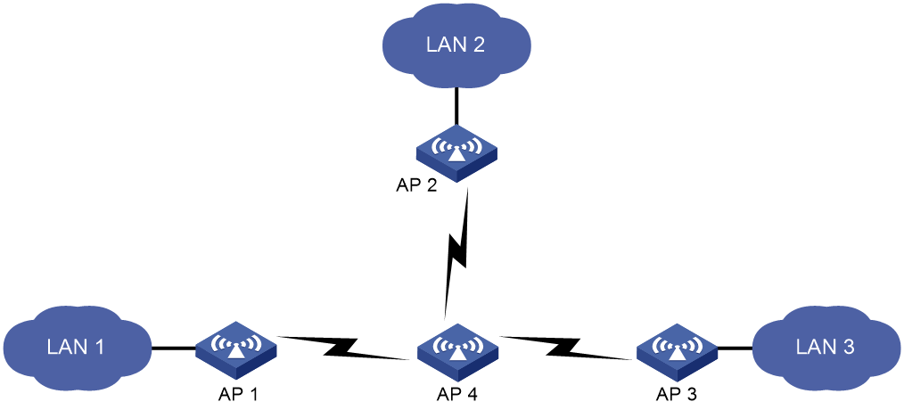
Point-to-point topology
As shown in Figure 3, you can set up a mesh link between two APs to connect two LANs.
Figure 3 WDS point to point topology

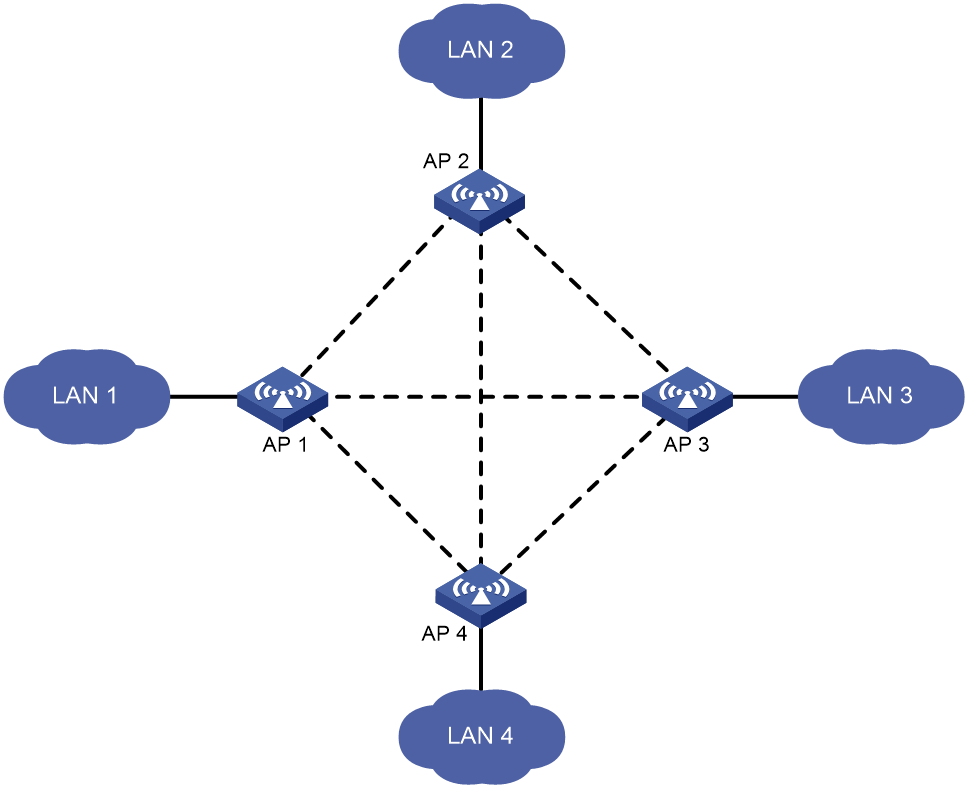
Star topology
As shown in Figure 4, you can set up mesh links between one central AP and multiple leaf APs to connect multiple LANs. In this topology, all data between LANs must traverse the central AP (AP 4 in this example).
Topology created without administrative intervention
Without administrative intervention, the WDS topology depends on the result of automatic neighbor discovery and mesh link establishment between APs.
Figure 5 Automatic topology setup
VLAN
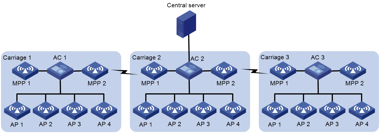
VLANs can be deployed in mesh networks for devices in different LANs to communicate with each other. Figure 6 shows the application of VLANs in high-speed railway mesh networks.
As shown in Figure 6, an AC and multiple APs are deployed in each carriage on a train. All devices are assigned to the same VLAN. Therefore, the two APs at both ends of each carriage can act as MPPs to establish mesh links with the MPPs on the adjacent carriages. Other APs provide WLAN access services. All devices communicate with the outside through the central server deployed in the middle of the train.
In this scenario, IP address conflict might occur because all ACs use the same configuration for easy configuration and maintenance. To address this issue, configure NAT on each AC and configure the mesh interfaces to allow the VLAN for MPP communications. For more information about NAT, see Network Connectivity Configuration Guide.
Figure 6 High-speed railway mesh network
MLSP
MLSP requires cooperation of both ACs and fat APs.
About this task
Mobile Link Switch Protocol (MLSP) is designed for subway application to provide stable data transmission through mesh links between onboard and trackside MPs. The onboard MPs are responsible for link selection, maintenance, and switchover.
With MLSP enabled, each onboard MP maintains one active link and multiple standby links at the same time. Only the active link is used for data transmission. An onboard MP keeps switching its active link during train movement to ensure stable data transmission.
In subway applications, signals can be transmitted over the air, in waveguides, or in linking coaxial (LCX) cables. Signals transmitted over the air are called air signal and signals transmitted in waveguides or LCX cables are called waveguide signals. As a best practice to avoid signal interference, deploy waveguides or LCX cables in areas with strong interference.
As shown in Figure 7, AP 1 through AP 4 are trackside MPs, and fat AP 1 and fat AP 2 are onboard MPs.
Figure 7 MLSP mesh network diagram
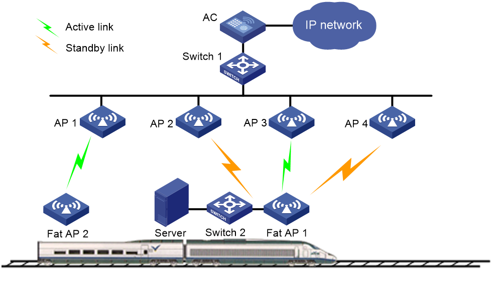
Air signal link switchover
An onboard MP uses a mesh link as a standby link if the RSSI on the link reaches or exceeds the sum of the link establishment threshold and the mesh link hold RSSI. If the MP does not have an active link, it uses the link as the active link.
An onboard MP switches to the optimal standby mesh link when one of the following conditions is met:
· The link hold timer expires and a standby link has an RSSI higher than the active link for a value that reaches or exceeds the link switchover threshold.
· The RSSI on the active link is lower than the mesh link hold RSSI.
· The RSSI on the active link reaches or exceeds the link saturation RSSI.
If no standby link is available, the MP keeps using the active link when the RSSI on the active link is lower than the mesh link hold RSSI. The MP terminates the active link when the active link RSSI reaches or exceeds the link saturation RSSI.
Waveguide signal link switchover
An MP prefers air transmission over waveguide transmission. If an MP detects both air signals and waveguide signals, it transmits signals over the air instead of in a waveguide or LCX cable.
In waveguide transmission, an onboard MP uses a link as a standby link if the link RSSI reaches or exceeds the sum of the link establishment threshold and the waveguide link hold RSSI. If the MP does not have an active link, it uses the link as the active link.
The switchover method for waveguide signal links depends on whether fast waveguide switchover is enabled. If fast waveguide switchover is enabled, an onboard MP switches to a waveguide link once the MP detects the link. If fast waveguide switchover is disabled, an onboard MP switches to the optimal standby waveguide link when one of the following conditions is met:
· The link hold timer expires and a standby link has an RSSI higher than the active link for a value that reaches or exceeds the link switchover threshold.
· The RSSI on the active link is lower than the waveguide link hold RSSI.
· The RSSI on the active link reaches or exceeds the link saturation RSSI.
If no standby link is available, the MP keeps using the active link when the RSSI on the active link is lower than the waveguide link hold RSSI. The MP terminates the active link when the active link RSSI reaches or exceeds the link saturation RSSI.
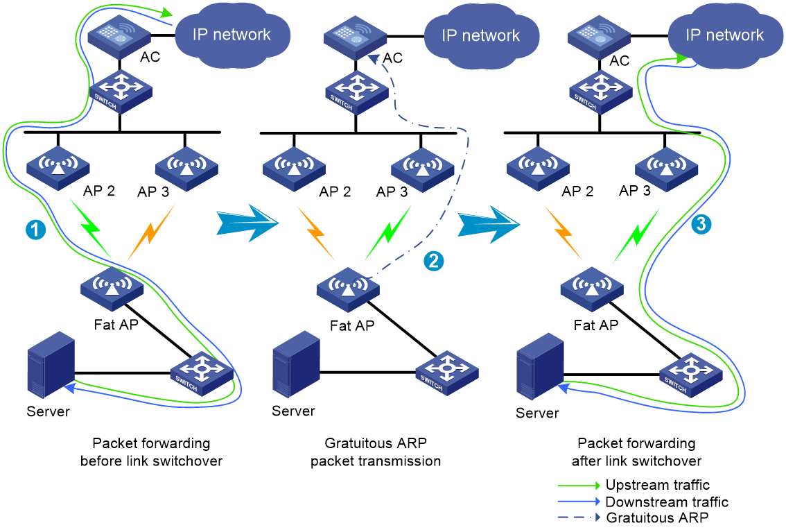
MLSP proxy
This feature enables an onboard MP to proxy an onboard device (typically an onboard server) for fast downlink packet forwarding path change when link switchover occurs.
As shown in Figure 8, an onboard MP uses the MAC address of the proxied device to send gratuitous ARP packets for MAC address table update of trackside MPs. This ensures fast transmission of downlink packets over the new active link after a link switchover.
Figure 8 Fast packet forwarding path change
Level of interval for sending keepalive requests
Onboard MPs determine whether a train has entered the garage based on the information carried in the probe responses from trackside MPs. If the train has entered the garage, onboard MPs will reduce the keepalive request sending interval based on the configured level of interval to prevent keepalive requests from consuming channel resources. A higher interval level indicates a longer interval to send keepalive requests.
Mesh peer blacklist or whitelist
You can configure the blacklist or whitelist to control whether an MP neighbor can establish a mesh link with the local MP.
If you configure both the blacklist and whitelist, only the whitelist takes effect and only MP neighbors in the whitelist can establish a mesh link with the local MP. If only the blacklist is configured, MP neighbors in the blacklist cannot establish a mesh link with the local MP.
Protocols and standards
· Draft P802.11s_D1.06
· ANSI/IEEE Std 802.11, 1999 Edition
· IEEE Std 802.11a
· IEEE Std 802.11b
· IEEE Std 802.11g
· IEEE Std 802.11i
· IEEE Std 802.11s
· IEEE Std 802.11-2004
· draft-ohara-capwap-lwapp-03
Restrictions and guidelines: WLAN mesh configuration
You can configure APs by using the following methods:
· Configure APs one by one in AP view.
· Assign APs to an AP group and configure the AP group in AP group view.
· Configure all APs in global configuration view.
For an AP, the settings made in these views for the same parameter take effect in descending order of AP view, AP group view, and global configuration view.
WLAN mesh tasks at a glance
To configure WLAN mesh, perform the following tasks:
2. Binding a mesh profile to a radio
3. (Optional.) Configuring a mesh policy
4. (Optional.) Binding a mesh policy to a radio
5. (Optional.) Disabling an MPP from sending probe requests
6. (Optional.) Enabling MPPs associated with the same AC to become mesh peers
7. (Optional.) Configuring the mesh peer blacklist or whitelist
8. (Optional.) Configuring mesh interfaces
9. (Optional.) Configuring MLSP
Configuring a mesh profile
Restrictions and guidelines
MPs on the same mesh network must use the same mesh ID and mesh security settings.
For correct link status detection, the keepalive interval at the sending end must be equal to or less than three times the keepalive interval at the receiving end.
Procedure
1. Enter system view.
system-view
2. Create a mesh profile and enter mesh profile view.
wlan mesh-profile mesh-profile-number
3. Specify a mesh ID.
mesh-id mesh-id
4. (Optional.) Configure mesh security.
¡ Configure a preshared key.
preshared-key { pass-phrase | raw-key } { cipher | simple } string
By default, no preshared key is configured.
¡ Enable SAE authentication and key management mode.
akm mode sae
By default, no authentication and key management mode is configured.
5. (Optional.) Set the mesh link keepalive interval.
link-keepalive keepalive-interval
The default mesh link keepalive interval is 2 seconds.
6. Enable the mesh profile.
mesh-profile enable
By default, a mesh profile is disabled.
Binding a mesh profile to a radio
About this task
For an AP to join a mesh network, you must bind a mesh profile to a radio on the AP. You can bind different mesh profiles to the radios on an AP for it to join different mesh networks.
Procedure
1. Enter system view.
system-view
2. Enter AP view or an AP group's AP model view.
¡ Enter AP view.
wlan ap ap-name
¡ Execute the following commands in sequence to enter an AP group's AP model view:
wlan ap-group group-name
ap-model ap-model
3. Enter radio view.
radio radio-id
4. Bind a mesh profile to the radio.
mesh-profile mesh-profile-number
By default:
¡ In radio view, an AP uses the configuration in an AP group's radio view.
¡ In an AP group's radio view, no mesh profile is bound to a radio.
Configuring a mesh policy
About this task
A mesh policy contains a set of mesh link setup and maintenance attributes.
Procedure
1. Enter system view.
system-view
2. Create a mesh policy and enter mesh policy view.
wlan mesh-policy policy-name
By default, a system-defined mesh policy exists. The policy name is default_mesh_policy.
3. Enable link initiation.
link-initiation enable
By default, link initiation is enabled.
4. (Optional.) Set the maximum number of mesh links.
link-maximum-number max-link-number
By default, the maximum number is 2.
5. (Optional.) Set the probe request interval.
probe-request-interval interval-value
By default, the probe request interval is 1000 ms.
As a best practice, set the value to a multiple of 100.
6. (Optional.) Set the mesh link hold RSSI, the minimum signal strength for a mesh link to be retained.
link-hold-rssi value
By default, the mesh link hold RSSI is 15.
Binding a mesh policy to a radio
About this task
By default, a system-defined mesh policy is bound to each radio. This system-defined mesh policy cannot be deleted or modified. To change the link setup and maintenance settings on a radio, you can bind a user-defined mesh policy to the radio to replace the system-defined mesh policy.
Procedure
1. Enter system view.
system-view
2. Enter AP view or an AP group's AP model view.
¡ Enter AP view.
wlan ap ap-name
¡ Execute the following commands in sequence to enter an AP group's AP model view:
wlan ap-group group-name
ap-model ap-model
3. Enter radio view.
radio radio-id
4. Bind a mesh policy to the radio.
mesh-policy name policy-name
By default:
¡ In radio view, an AP uses the configuration in an AP group's radio view.
¡ In an AP group's radio view, the system-defined mesh policy default_mesh_policy is bound to a radio.
Disabling an MPP from sending probe requests
About this task
As the point that connects the WLAN mesh network to a wired network, an MPP might need to establish a large number of mesh links. To maintain its performance, you can disable the MPP from sending probe requests for neighbor discovery. The MPP will only respond to the probe requests from other MPs.
Procedure
1. Enter system view.
system-view
2. Enter AP view, AP group view, or global configuration view.
¡ Enter AP view.
wlan ap ap-name
¡ Enter AP group view.
wlan ap-group group-name
¡ Enter global configuration view.
wlan global-configuration
3. Disable the MPP from sending probe requests.
portal-service enable
¡ In AP view, an AP uses the configuration in AP group view. If no setting is configured in AP group view, the AP uses the configuration in global configuration view.
¡ In AP group view, an AP uses the configuration in global configuration view.
¡ In global configuration view, MPPs can send probe requests.
Enabling MPPs associated with the same AC to become mesh peers
About this task
To avoid loops, MPPs associated with the same AC cannot become mesh peers by default. Perform this task to enable MPPs associated with the same AC to become mesh peers. However, you must make sure the mesh links established between MPPs associated with the same AC are not in VLAN 1.
Procedure
1. Enter system view.
system-view
2. Enter global configuration view.
wlan global-configuration
3. Enable MPPs associated with the same AC to become mesh peers.
mesh-peer intra-ac-mpp enable
By default, to avoid loops, MPPs associated with the same AC cannot become mesh peers.
Configuring the mesh peer blacklist or whitelist
1. Enter system view.
system-view
2. Enter AP view or an AP group's AP model view.
¡ Enter AP view.
wlan ap ap-name
¡ Execute the following commands in sequence to enter an AP group's AP model view:
wlan ap-group group-name
ap-model ap-model
3. Enter radio view.
radio radio-id
4. Add the MAC address of an MP to the mesh peer blacklist or whitelist.
mesh peer-mac-address [ blacklist ] mac-address
By default:
¡ In radio view, an AP uses the configuration in an AP group's radio view.
¡ In an AP group's radio view, no mesh peer blacklist or whitelist exists.
Configuring mesh interfaces
Tasks at a glance
To configure mesh interfaces, perform the following tasks:
2. Set port attributes
¡ Setting access port attributes for a mesh interface
¡ Setting trunk port attributes for a mesh interface
¡ Setting hybrid port attributes for a mesh interface
3. Binding a mesh interface to a radio
Creating a mesh interface
About this task
Create mesh interfaces to allow mesh networks in the same VLAN to communicate with each other.
Procedure
1. Enter system view.
system-view
2. Enter AP view or AP group view.
¡ Enter AP view.
wlan ap ap-name
¡ Enter AP group view.
wlan ap-group group-name
3. Create a mesh interface and enter its view.
interface wlan-mesh interface-number
Setting access port attributes for a mesh interface
About this task
An access port allows only one VLAN.
Restrictions and guidelines
Make sure the VLAN exists before setting access port attributes for a mesh interface.
Procedure
1. Enter system view.
system-view
2. Enter AP view or AP group view.
¡ Enter AP view.
wlan ap ap-name
¡ Enter AP group view.
wlan ap-group group-name
3. Enter WLAN-mesh interface view.
interface wlan-mesh interface-number
4. Set the link type to access for the mesh interface.
mesh-port link-type access
By default, the link type is access.
5. Assign the access-type mesh interface to a VLAN.
mesh-port access vlan vlan-id
By default, an access port belongs to VLAN 1.
Setting trunk port attributes for a mesh interface
About this task
A trunk port allows multiple VLANs.
Restrictions and guidelines
To change the link type of a port between trunk and hybrid, first set the link type to access.
You can specify a non-existent VLAN as the port VLAN for a trunk port.
To enable a trunk port to transmit packets from its port VLAN, you must assign the trunk port to the port VLAN.
Procedure
1. Enter system view.
system-view
2. Enter AP view or AP group view.
¡ Enter AP view.
wlan ap ap-name
¡ Enter AP group view.
wlan ap-group group-name
3. Enter WLAN-mesh interface view.
interface wlan-mesh interface-number
4. Set the link type to trunk for the mesh interface.
mesh-port link-type trunk
By default, the link type is access.
5. Set the PVID for the trunk port.
mesh-port trunk pvid vlan vlan-id
By default, the PVID of a trunk port is VLAN 1.
6. Assign the trunk-type mesh interface to a VLAN.
mesh-port trunk permit vlan { vlan-id-list | all }
By default, a trunk port permits only VLAN 1.
Setting hybrid port attributes for a mesh interface
About this task
A hybrid port allows multiple VLANs.
Restrictions and guidelines
To change the link type of a port between trunk and hybrid, first set the link type to access.
You can specify a non-existent VLAN as the port VLAN for a hybrid port.
Make sure you assign the hybrid port to VLANs that already exist.
To enable a hybrid port to transmit packets from its port VLAN, you must assign the hybrid port to the port VLAN.
Procedure
1. Enter system view.
system-view
2. Enter AP view or AP group view.
¡ Enter AP view.
wlan ap ap-name
¡ Enter AP group view.
wlan ap-group group-name
3. Enter WLAN-mesh interface view.
interface wlan-mesh interface-number
4. Set the link type to hybrid for the mesh interface.
mesh-port link-type hybrid
By default, the link type is access.
5. Set the PVID for the hybrid port.
mesh-port hybrid pvid vlan vlan-id
By default, the PVID of a hybrid port is the ID of the VLAN to which the port belongs when its link type is access.
6. Assign the hybrid-type mesh interface to the specified VLANs.
mesh-port hybrid vlan vlan-id-list { tagged | untagged }
By default, a hybrid port is an untagged member of the VLAN to which the port belongs when its link type is access.
Binding a mesh interface to a radio
Restrictions and guidelines
Mesh interfaces created in AP view can be bound to a radio only in radio view. Mesh interfaces created in AP group view can be bound to a radio in both radio view and AP group radio view.
You can bind only one mesh interface to a radio.
Procedure
1. Enter system view.
system-view
2. Enter AP view or an AP group's AP model view.
¡ Enter AP view.
wlan ap ap-name
¡ Execute the following commands in sequence to enter an AP group's AP model view:
wlan ap-group group-name
ap-model ap-model
3. Enter radio view.
radio radio-id
4. Bind a mesh interface to the radio.
mesh-interface interface-number
By default:
¡ In radio view, an AP uses the configuration in an AP group's radio view.
¡ In an AP group's radio view, no mesh interface is bound to a radio.
Configuring MLSP
Prerequisites for MLSP
Make sure you have finished basic mesh profile and mesh policy configuration and the onboard MPs can successfully establish mesh links with the trackside MPs.
Configuring trackside MPs
1. Enter system view.
system-view
2. Enter mesh policy view.
wlan mesh-policy policy-name
3. Enable mesh link initiation.
link-initiation enable
By default, mesh link initiation is enabled.
4. Specify the signal transmission method.
transmission-method { air | waveguide }
By default, signals are transmitted over the air.
5. (Optional.) Configure mesh link establishment and maintenance:
¡ Set the mesh link establishment threshold.
link-establish-threshold threshold-value
By default, the mesh link establishment threshold is 5 dBm.
¡ Set the mesh link hold RSSI.
link-hold-rssi value
By default, the mesh link hold RSSI is 15.
As a best practice, set the link hold RSSI for trackside MPs smaller than the link hold RSSI for onboard MPs in case the trackside MPs terminates mesh links actively.
¡ Set the mesh link saturation RSSI.
link-saturation-rssi value
By default, the mesh link saturation RSSI is 150.
¡ Disable temporary mesh link establishment.
undo temporary-link enable
By default, temporary mesh link establishment is enabled.
To prevent frequent temporary mesh link establishment from affecting trackside MP performance, you can disable this feature.
¡ Set the level of interval for sending keepalive requests.
active-link keepalive-transmit-level value
By default, the level of interval for sending keepalive request is 0.
Set the level on the AC that manages trackside MPs. Trackside MPs inform onboard MPs of the level to control the keepalive requests sent by the onboard MPs.
Display and maintenance commands for WLAN mesh
Execute display commands in any view.
|
Task |
Command |
|
Display mesh link information. |
display wlan mesh-link ap [ name ap-name ] [ verbose ] |
|
Display mesh policy information. |
display wlan mesh-policy [ mesh-policy-name ] |
|
Display mesh profile information. |
display wlan mesh-profile [ mesh-profile-number ] |
WLAN mesh configuration examples
The AP models and serial numbers in this document are used only as examples. Support for AP models and serial numbers depends on the AC model.
Example: Configuring WLAN mesh
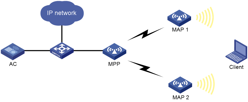
Network configuration
As shown in Figure 9, establish an 802.11n 5GHz WLAN mesh network to provide network access for the clients. Configure the MP and MAPs to establish mesh links on channel 149.
Procedure
1. Configure a mesh profile:
# Create a mesh profile.
<AC> system-view
[AC] wlan mesh-profile 1
# Set the mesh ID to 1.
[AC-wlan-mesh-profile-1] mesh-id 1
# Enable SAE for authentication and key management.
[AC-wlan-mesh-profile-1] akm mode sae
# Configure a preshared key.
[AC-wlan-mesh-profile-1] preshared-key pass-phrase simple 12345678
# Enable the mesh profile.
[AC-wlan-mesh-profile-1] mesh-profile enable
[AC-wlan-mesh-profile-1] quit
2. Configure a service template.
[AC] wlan service-template service1
[AC-wlan-st-service1] ssid mesh-network
[AC-wlan-st-service1] service-template enable
[AC-wlan-st-service1] quit
3. Configure settings for the MPP:
# Create an AP template for the MPP. Make sure you select the correct AP model and specify the correct serial ID.
[AC] wlan ap mpp model WA4320i-ACN
[AC-wlan-ap-mpp] serial-id 210235A29G007C000020
# Bind the mesh profile to the MPP's radio 1.
[AC-wlan-ap-mpp] radio 1
[AC-wlan-ap-mpp-radio-1] mesh-profile 1
# Set the radio type of the MPP's radio 1 to 802.11n (5GHz).
[AC-wlan-ap-mpp-radio-1] type dot11an
# Set the working channel of the radio to 149.
[AC-wlan-ap-mpp-radio-1] channel 149
# Enable the radio.
[AC-wlan-ap-mpp-radio-1] radio enable
[AC-wlan-ap-mpp-radio-1] quit
# Disable the MPP from sending neighbor probe requests.
[AC-wlan-ap-mpp] portal-service enable
[AC-wlan-ap-mpp] quit
4. Configure settings for the MAPs:
# Create an AP template for MAP 1. Make sure you select the correct AP model and specify the correct serial ID.
[AC] wlan ap map1 model WA4320i-ACN
[AC-wlan-ap-map1] serial-id 210235A29G007C000050
# Bind the mesh profile to the MAP's radio 1.
[AC-wlan-ap-map1] radio 1
[AC-wlan-ap-map1-radio-1] mesh-profile 1
# Bind the service template to the MAP's radio 1.
[AC-wlan-ap-map1-radio-1] service-template service1
# Set the radio type of the MAP's radio 1 to 802.11n (5GHz).
[AC-wlan-ap-map1-radio-1] type dot11an
# Set the working channel of the radio to 149.
[AC-wlan-ap-map1-radio-1] channel 149
# Add the MAC address of radio 1 on the MPP to the mesh peer whitelist to avoid loops. MAP 1 can set up a mesh link only with the MPP.
[AC-wlan-ap-map1-radio-1] mesh peer-mac-address 77a2-c25d-e316
# Enable the radio.
[AC-wlan-ap-map1-radio-1] radio enable
[AC-wlan-ap-map1-radio-1] quit
[AC-wlan-ap-map1] quit
# Configure settings for MAP 2 in the same way settings for MAP 1 are configured.
[AC] wlan ap map2 model WA4320i-ACN
[AC-wlan-ap-map2] serial-id 210235A29G007C000090
[AC-wlan-ap-map2] radio 1
[AC-wlan-ap-map2-radio-1] mesh-profile 1
[AC-wlan-ap-map2-radio-1] service-template service1
[AC-wlan-ap-map2-radio-1] type dot11an
[AC-wlan-ap-map2-radio-1] channel 149
[AC-wlan-ap-map2-radio-1] mesh peer-mac-address 77a2-c25d-e316
[AC-wlan-ap-map2-radio-1] radio enable
[AC-wlan-ap-map2-radio-1] quit
[AC-wlan-ap-map2] quit
[AC] quit
Verifying the configuration
# Verify that the MPP and MAPs can establish mesh links.
<AC> display wlan mesh-link ap
AP Name: mpp
Peer Local Status RSSI Packets(Rx/Tx)
4a9b-c5bb-e43f 77a2-c25d-e316 Forwarding 22 6058/1900
a6b5-1c5a-22ff 77a2-c25d-e316 Forwarding 35 5354/1900
AP Name: map1
Peer Local Status RSSI Packets(Rx/Tx)
77a2-c25d-e316 4a9b-c5bb-e43f Forwarding 22 1900/6058
AP Name: map2
Peer Local Status RSSI Packets(Rx/Tx)
77a2-c25d-e316 a6b5-1c5a-22ff Forwarding 35 1900/5354
# Verify that the clients have associated with their respective APs.
<AC> display wlan client
Total number of clients: 1
MAC address Username AP name R IP address VLAN
000f-e265-6400 N/A mpp 1 1.1.1.1 300
Example: Configuring VLAN settings for a WLAN mesh network
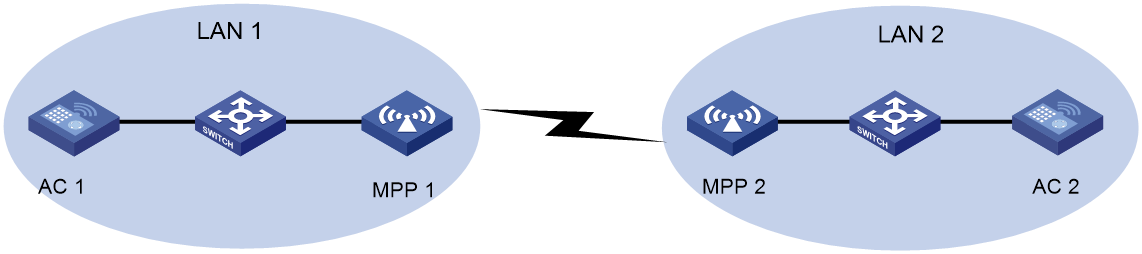
Network configuration
As shown in Figure 10, both LAN 1 and LAN 2 belong to VLAN 2. Configure MPP 1 and MPP 2 to establish a mesh link on channel 149, and to permit traffic from VLAN 2.
Procedure
1. Configure a mesh profile:
# Create a mesh profile.
<AC1> system-view
[AC1] wlan mesh-profile 1
# Set the mesh ID to 1.
[AC1-wlan-mesh-profile-1] mesh-id 1
# Enable SAE for authentication and key management.
[AC1-wlan-mesh-profile-1] akm mode sae
# Configure a preshared key.
[AC1-wlan-mesh-profile-1] preshared-key pass-phrase simple 12345678
# Enable the mesh profile.
[AC1-wlan-mesh-profile-1] mesh-profile enable
[AC1-wlan-mesh-profile-1] quit
2. Configure a service template.
[AC1] wlan service-template service1
[AC1-wlan-st-service1] ssid mesh-network
[AC1-wlan-st-service1] service-template enable
[AC1-wlan-st-service1] quit
3. Configure settings for the MPP:
# Create an AP template for the MPP. Make sure you select the correct AP model and specify the correct serial ID.
[AC1] wlan ap mpp1 model WA4320i-ACN
[AC1-wlan-ap-mpp1] serial-id 210235A29G007C000020
# Bind the mesh profile to radio 1 of the MPP.
[AC1-wlan-ap-mpp1] radio 1
[AC1-wlan-ap-mpp1-radio-1] mesh-profile 1
# Set the radio type for radio 1 of the MPP to 802.11n (5GHz).
[AC1-wlan-ap-mpp1-radio-1] type dot11an
# Set the working channel of the radio to 149.
[AC1-wlan-ap-mpp1-radio-1] channel 149
# Enable the radio.
[AC1-wlan-ap-mpp1-radio-1] radio enable
[AC1-wlan-ap-mpp1-radio-1] quit
4. Configure the mesh interface:
# Create mesh interface 1.
[AC1-wlan-ap-mpp1] interface wlan-mesh 1
[AC1-wlan-ap-mpp1-wlan-mesh-1] quit
# Bind the mesh interface to radio 1 of the MPP.
[AC1-wlan-ap-mpp1] radio 1
[AC1-wlan-ap-mpp1-radio-1] mesh-interface 1
[AC1-wlan-ap-mpp1-radio-1] quit
# Set the link type to trunk.
[AC1-wlan-ap-mpp1] interface wlan-mesh 1
[AC1-wlan-ap-mpp1-wlan-mesh-1] mesh-port link type trunk
# Assign the trunk port to VLAN 2.
[AC1-wlan-ap-mpp1-wlan-mesh-1] mesh-port trunk permit vlan 2
[AC1-wlan-ap-mpp1-wlan-mesh-1] quit
# Enable remote configuration assignment.
[AC1-wlan-ap-mpp1] remote-configuration enable
5. Configure AC 2 in the same way AC 1 is configured.
Verifying the configuration
# Configure VLAN-interface 2 on both AC 1 and AC 2 to verify that AC 1 and AC 2 can ping each other successfully.
Example: Configuring MLSP
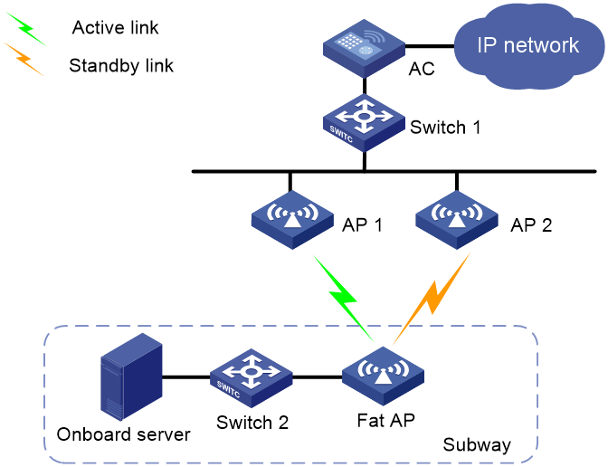
Network configuration
As shown in Figure 11, trackside MPs (AP 1 and AP 2) are connected to the AC through Switch 1, and the onboard MP (fat AP) is connected to the onboard server through Switch 2. Configure MLSP for the onboard MP to communicate with trackside MPs.
Procedure
1. Configure the onboard MP:
# Create a mesh profile.
<FatAP> system-view
[FatAP] wlan mesh-profile 1
# Set the mesh ID to 1.
[FatAP-wlan-mesh-profile-1] mesh-id 1
# Enable SAE for authentication and key management.
[FatAP-wlan-mesh-profile-1] akm mode sae
# Configure a preshared key.
[FatAP-wlan-mesh-profile-1] preshared-key pass-phrase simple 12345678
# Enable the mesh profile.
[FatAP-wlan-mesh-profile-1] mesh-profile enable
[FatAP-wlan-mesh-profile-1] quit
# Create mesh policy 1 and enable mesh link initiation.
[FatAP] wlan mesh-policy 1
[FatAP-wlan-mesh-policy-1] link-initiation enable
# Enable MLSP.
[FatAP-wlan-mesh-policy-1] mlsp enable
# Set the mesh link establishment threshold to 3.
[FatAP-wlan-mesh-policy-1] link-establish-threshold 3
# Set the mesh link hold RSSI to 20.
[FatAP-wlan-mesh-policy-1] link-hold-rssi 20
# Set the mesh link saturation RSSI to 100.
[FatAP-wlan-mesh-policy-1] link-saturation-rssi 100
# Set the mesh link hold time to 4000.
[FatAP-wlan-mesh-policy-1] link-hold-time 4000
# Set the mesh link keepalive packet limit for the active link to 5.
[FatAP-wlan-mesh-policy-1] active-link keepalive-count 5
# Set the mesh link switchover threshold to 5.
[FatAP-wlan-mesh-policy-1] link-switch-threshold 5
# Set the probe request interval to 100.
[FatAP-wlan-mesh-policy-1] probe-request-interval 100
# Configure the MP to proxy the onboard server.
[FatAP-wlan-mesh-policy-1] mlsp-proxy mac-address 000f-e201-0101 vlan 1
[FatAP-wlan-mesh-policy-1] quit
# Bind mesh profile 1 to radio interface WLAN-Radio 1/0/1.
[FatAP] interface wlan-radio 1/0/1
[FatAP-WLAN-Radio1/0/1] mesh-profile 1
# Set the radio mode to 802.11n (5 GHz).
[FatAP-WLAN-Radio1/0/1] type dot11an
# Set the working channel to 149.
[FatAP-WLAN-Radio1/0/1] channel 149
# Bind mesh policy 1 to radio interface WLAN-Radio 1/0/1.
[FatAP-WLAN-Radio1/0/1] mesh-policy name 1
# Enable the radio interface.
[FatAP-WLAN-Radio1/0/1] undo shutdown
[FatAP-WLAN-Radio1/0/1] quit
2. Configure the trackside MPs:
# Create a mesh profile.
<AC> system-view
[AC] wlan mesh-profile 1
# Set the mesh ID to 1.
[AC-wlan-mesh-profile-1] mesh-id 1
# Enable SAE for authentication and key management.
[AC-wlan-mesh-profile-1] akm mode sae
# Configure a preshared key.
[AC-wlan-mesh-profile-1] preshared-key pass-phrase simple 12345678
# Enable the mesh profile.
[AC-wlan-mesh-profile-1] mesh-profile enable
[AC-wlan-mesh-profile-1] quit
# Create mesh policy 1 and disable mesh link initiation.
[AC] wlan mesh-policy 1
[AC-wlan-mesh-policy-1] undo link-initiation enable
# Set the mesh link establishment threshold to 3.
[AC-wlan-mesh-policy-1] link-establish-threshold 3
# Set the mesh link hold RSSI to 5.
[AC-wlan-mesh-policy-1] link-hold-rssi 5
# Set the mesh link saturation RSSI to 100.
[AC-wlan-mesh-policy-1] link-saturation-rssi 100
# Disable temporary mesh link establishment.
[AC-wlan-mesh-policy-1] undo temporary-link enable
[AC-wlan-mesh-policy-1] quit
# Create manual AP ap1 and specify its serial ID.
[AC] wlan ap ap1 model WA4320i-ACN
[AC-wlan-ap-ap1] serial-id 210235A29G007C000050
# Bind mesh profile 1 to radio 1.
[AC-wlan-ap-ap1] radio 1
[AC-wlan-ap-ap1-radio-1] mesh-profile 1
# Bind mesh policy 1 to radio 1.
[AC-wlan-ap-ap1-radio-1] mesh-policy name 1
# Set the radio mode to 802.11n (5 GHz).
[AC-wlan-ap-ap1-radio-1] type dot11an
# Set the working channel to 149.
[AC-wlan-ap-ap1-radio-1] channel 149
# Enable the radio.
[AC-wlan-ap-ap1-radio-1] radio enable
[AC-wlan-ap-ap1-radio-1] quit
[AC-wlan-ap-ap1] quit
# Create manual AP ap2 and specify its serial ID.
[AC] wlan ap ap2 model WA4320i-ACN
[AC-wlan-ap-ap2] serial-id 210235A29G007C000090
# Bind mesh profile 1 to radio 1.
[AC-wlan-ap-ap2] radio 1
[AC-wlan-ap-ap2-radio-1] mesh-profile 1
# Bind mesh policy 1 to radio 1.
[AC-wlan-ap-ap2-radio-1] mesh-policy name 1
# Set the radio mode to 802.11n (5 GHz).
[AC-wlan-ap-ap2-radio-1] type dot11an
# Set the working channel to 149.
[AC-wlan-ap-ap2-radio-1] channel 149
# Enable the radio.
[AC-wlan-ap-ap2-radio-1] radio enable
[AC-wlan-ap-ap2-radio-1] quit
[AC-wlan-ap-ap2] quit
Verifying the configuration
# Display mesh link information on the onboard MP to verify that mesh links have been established.
<FatAP> display wlan mesh-link
Peer MAC RSSI BSSID Interface Link state Online time
d461-fe59-8620 74 d461-fe59-8380 WLAN-MeshLink129 Active(an) 00h 02m 27s
d461-fe59-87d0 49 d461-fe59-8380 WLAN-MeshLink130 Standby(an) 00h 02m 07s
# Display mesh link information on the onboard MP to verify that an active/standby link switchover has occurred.
<FatAP> display wlan mesh-link
Peer MAC RSSI BSSID Interface Link state Online time
d461-fe59-8620 52 d461-fe59-8380 WLAN-MeshLink129 Standby(an) 00h 02m 37s
d461-fe59-87d0 72 d461-fe59-8380 WLAN-MeshLink130 Active(an) 00h 02m 17s