- Table of Contents
-
- 10-High Availability Configuration Guide
- 00-Preface
- 01-Ethernet OAM configuration
- 02-CFD configuration
- 03-DLDP configuration
- 04-RRPP configuration
- 05-ERPS configuration
- 06-Smart Link configuration
- 07-Monitor Link configuration
- 08-Error code detection configuration
- 09-VRRP configuration
- 10-BFD configuration
- 11-Track configuration
- 12-Process placement configuration
- 13-S-Trunk configuration
- Related Documents
-
| Title | Size | Download |
|---|---|---|
| 13-S-Trunk configuration | 284.28 KB |
S-Trunk protocol packet timeout
Traffic forwarding and failure handling mechanisms
Sequence number check on S-Trunk protocol packets
S-Trunk protocol packet authentication
Restrictions and guidelines: S-Trunk configuration
Configuring S-Trunk system settings
Restrictions and guidelines for S-Trunk system settings
Configuring the LACP system MAC address
Setting the LACP system priority
Setting the LACP system number
Configuring a description for a smart trunk
Setting the role priority of the device
Setting the destination UDP port of S-Trunk protocol packets
Configuring S-Trunk protocol packet parameters
Setting the S-Trunk protocol packet transmission interval
Setting the multiplier for calculating the S-Trunk protocol packet timeout
Assigning an interface to a smart trunk
Configuring the role of an aggregate interface in a smart trunk
Configuring reversion settings for a smart trunk
Disabling reversion to the primary interface
Associating a smart trunk with a BFD session
Enabling sequence number check on S-Trunk protocol packets
Enabling S-Trunk protocol packet authentication
Display and maintenance commands for S-Trunk
S-Trunk configuration examples
Example: Configuring S-Trunk in an MPLS L2VPN network
Configuring S-Trunk
About S-Trunk
Smart Trunk (S-Trunk) is used on two PEs that provide dual-homed access for a CE for link and node redundancy. It virtualizes two PEs into one system through a multichassis link aggregation called smart trunk.
Application scenario
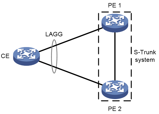
S-Trunk is used in the dual-homing scenario shown in Figure 1 to ensure service continuity upon failure of one PE. S-Trunk virtualizes the PEs into an S-Trunk system. To the CE, the S-Trunk system is one device. A smart trunk is configured on the PEs to aggregate the links between the CE and PEs. When a link or PE fails, its traffic is automatically switched to the other available links or PE.
Figure 1 S-Trunk application scenario
S-Trunk network model
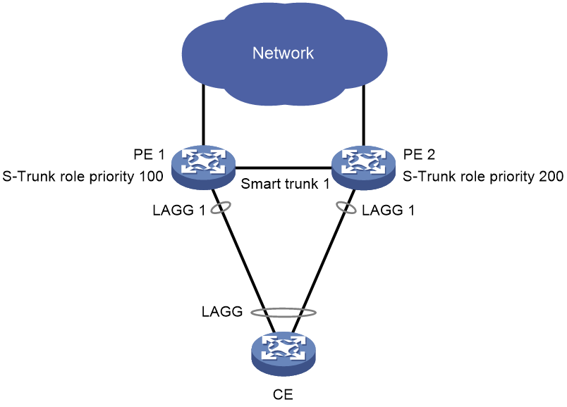
As shown in Figure 2, each member device in the S-Trunk system is assigned the primary or secondary role based on its S-Trunk role priority. When both devices are operating correctly, only the primary S-Trunk member device forwards traffic. When the primary S-Trunk member device fails, the secondary S-Trunk member device takes over to forward all traffic.
A smart trunk contains two CE-facing aggregate interfaces as its member interfaces. S-Trunk also defines the primary and secondary roles for the member interfaces in a smart trunk. For the same smart trunk, typically the role of a smart trunk member interface is the same as the role of the S-Trunk member device that hosts that interface.
Figure 2 S-Trunk network model
S-Trunk protocol packet timeout
The S-Trunk protocol packet timeout equals the S-Trunk protocol packet transmission interval multiplied by the multiplier for calculating the S-Trunk protocol packet timeout. The S-Trunk member devices periodically send S-Trunk hello packets that contain the S-Trunk protocol packet timeout to each other. An S-Trunk member device uses the peer's S-Trunk protocol packet timeout to determine whether the peer is down. If the secondary S-Trunk member device has not received S-Trunk hello packets when this timeout expires, it takes over the primary role.
S-Trunk system setup process
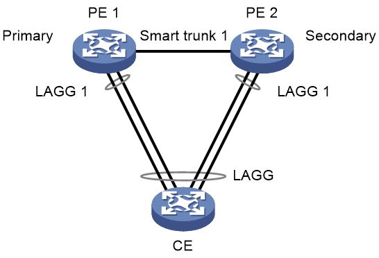
As shown in Figure 3, perform the following tasks to configure a smart trunk:
1. Create a CE-facing aggregate interface and a smart trunk with the same ID on each PE, and assign the aggregate interfaces to the smart trunk.
2. Configure a link aggregation group on the CE and assign the interfaces connected to the PEs to the link aggregation group.
The PEs set up an S-Trunk system as follows:
1. PE 1 and PE 2 exchange S-Trunk protocol packets to advertise their S-Trunk configuration. The PEs form an S-Trunk system if the following requirements are met:
¡ They use the same LACP system MAC address and LACP system priority.
¡ They use different LACP system numbers.
¡ The S-Trunk protocol packets are destined for the same UDP port, and the source and destination IP addresses of incoming S-Trunk protocol packets are consistent with those configured on each PE.
¡ The IP addresses used for S-Trunk protocol packet transmission are reachable to each other.
2. The PEs determine the device roles and interface roles for the smart trunk.
¡ Determining device roles—The PEs compare their role priorities and elect the primary device through S-Trunk protocol packets. As shown in Figure 3, PE 1 is assigned the primary role, and PE 2 is assigned the secondary role.
¡ Determining interface roles—Each PE assigns the primary or secondary role to its smart trunk member interface based on its S-Trunk role and peer status. As shown in Figure 3, interface LAGG 1 on PE 1 is assigned the primary role, and interface LAGG 1 on PE 2 is assigned the secondary role.
3. The S-Trunk system forwards traffic through the primary S-Trunk member device.
Figure 3 S-Trunk system setup process
Traffic forwarding and failure handling mechanisms
Typical traffic forwarding process
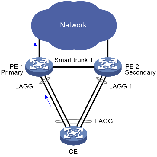
When both S-Trunk member devices are operating correctly, the smart trunk member interface on the primary member device forwards traffic. As shown in Figure 4, interface LAGG 1 on primary member device PE 1 is forwarding the traffic of CE 1. Interface LAGG 1 on PE 2 is the secondary member interface and is placed in down state.
Figure 4 Typical traffic forwarding process
Primary member interface failure handling mechanism
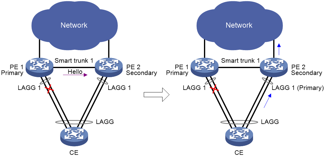
When the primary member interface in a smart trunk fails, the smart trunk forwards traffic through the other member interface.
As shown in Figure 5, when the link between the CE and PE 1 fails, PE 1 notifies PE 2 of the failure of LAGG 1 through S-Trunk hello packets. After receiving the S-Trunk hello packets, PE 2 assigns the primary role to its LAGG 1 and brings the interface up to forward the traffic of the CE.
Figure 5 Primary interface failure handling mechanism
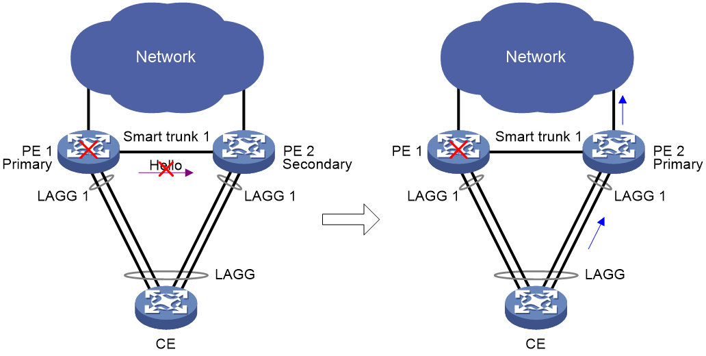
Primary member device failure handling mechanism
When the primary member device fails, the secondary member device takes over the primary role to forward all traffic.
As shown in Figure 6, if PE 1 fails, PE 2 cannot receive S-Trunk hello packets and determines that PE 1 is down upon expiration of the S-Trunk protocol packet timeout. Then, PE 2 becomes the primary member device and brings up LAGG 1 to forward the traffic of the CE.
Figure 6 Primary member device failure handling mechanism
BFD association with S-Trunk
Bidirectional forwarding detection (BFD) provides faster peer failure detection than the S-Trunk protocol packet timeout mechanism. After you associate a smart trunk with a BFD session, BFD monitors the status of the BFD session to detect peer status changes on each S-Trunk member device. When the BFD session goes down, BFD reports the event to S-Trunk. For more information about BFD, see High Availability Configuration Guide.
S-Trunk reversion mechanism
S-Trunk allows a smart trunk to revert to the former primary member interface after that interface recovers from failure. You can set a reversion delay timer for the S-Trunk member devices to finish network convergence before the reversion.
Sequence number check on S-Trunk protocol packets
As shown in Figure 7, PE 1 and PE 2 are the primary and secondary member devices, respectively. An attacker might intercept the S-Trunk protocol packets sent by PE 1. If the attacker sends the intercepted packets to PE 2 when PE 1 is down, PE 2 will be unaware of the failure of PE 1 and retain its secondary role. As a result, traffic interruption will occur.
Figure 7 Sequence number check on S-Trunk protocol packets
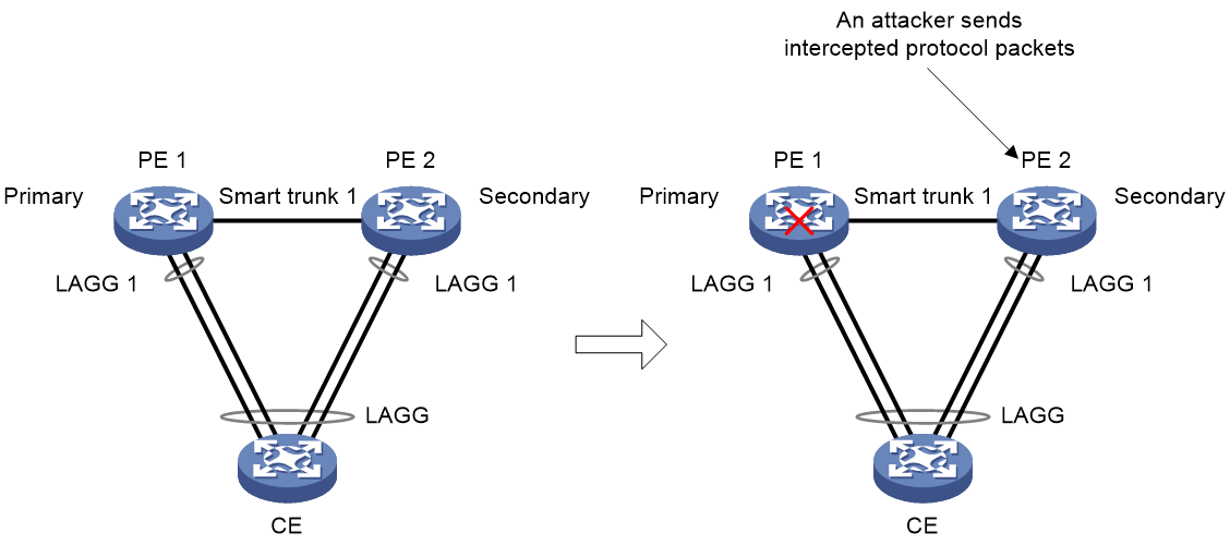
S-Trunk uses sequence number check to protect the S-Trunk member devices from replay attacks. An S-Trunk member device drops an S-Trunk protocol packet if its sequence number is the same as that of a previously received packet or is smaller than that of the last received packet.
S-Trunk protocol packet authentication
S-Trunk uses S-Trunk protocol packet authentication to prevent packet tampering. Each S-Trunk protocol packet sent by an S-Trunk member device carries a message digest that is computed based on the packet content. When receiving an S-Trunk protocol packet, an S-Trunk member device computes a message digest and compares it with the message digest in the packet. If the message digests are consistent, the packet is considered legal.
Restrictions and guidelines: S-Trunk configuration
The link-aggregation selected-port maximum and link-aggregation selected-port minimum commands do not take effect on an aggregate interface in a smart trunk. For more information about these commands, see Ethernet link aggregation configuration in Layer 2—LAN Switching Configuration Guide.
As a best practice to ensure quick link failure detection, enable BFD for the link aggregation between a CE and a PE. For more information about BFD configuration for link aggregation, see Layer 2—LAN Switching Configuration Guide.
As a best practice to enhance security, enable both sequence number check and S-Trunk protocol packet authentication.
S-Trunk tasks at a glance
To configure a smart trunk, perform the following tasks:
1. Configuring S-Trunk system settings
¡ Configuring the LACP system MAC address
¡ Setting the LACP system priority
¡ Setting the LACP system number
¡ Configuring a description for a smart trunk
¡ Setting the destination UDP port of S-Trunk protocol packets
¡ Configuring S-Trunk protocol packet parameters
¡ Setting the S-Trunk protocol packet transmission interval
¡ Setting the multiplier for calculating the S-Trunk protocol packet timeout
4. Assigning an interface to a smart trunk
5. Configuring the role of an aggregate interface in a smart trunk
6. Configuring reversion settings for a smart trunk
¡ Disabling reversion to the primary interface
7. Associating a smart trunk with a BFD session
8. Enabling sequence number check on S-Trunk protocol packets
9. Enabling S-Trunk protocol packet authentication
Configuring S-Trunk system settings
Restrictions and guidelines for S-Trunk system settings
For two PEs in an S-Trunk system to be identified as one device, you must configure the same LACP system MAC address and LACP system priority on them. You must assign different LACP system numbers to the PEs.
On an S-Trunk member device, all smart trunks use the same S-Trunk system settings. Modifying the S-Trunk system settings might cause incorrect operations of smart trunks. As a best practice, modify the settings before you configure smart trunks on an S-Trunk system.
Configuring the LACP system MAC address
About this task
For two PEs in an S-Trunk system to be identified as one device, you must configure the same LACP system MAC address on them.
Restrictions and guidelines
As a best practice to avoid MAC address collision, use the bridge MAC address of one S-Trunk member device as the LACP system MAC address.
Procedure
1. Enter system view.
system-view
2. Configure the LACP system MAC address.
lacp system-mac mac-address
By default, the LACP system MAC address is not configured.
Setting the LACP system priority
1. Enter system view.
system-view
2. Set the LACP system priority.
lacp system-priority priority
By default, the LACP system priority is 32768.
For more information about the LACP system priority, see Ethernet link aggregation in Layer 2—LAN Switching Configuration Guide.
Setting the LACP system number
About this task
You must assign different LACP system numbers to the member devices in an S-Trunk system. The devices will generate different interface indexes for the smart trunk member interfaces with the same interface number.
Restrictions and guidelines
The LACP system number takes effect only on aggregate interfaces in smart trunks. Aggregate interfaces not in smart trunks do not use the configured LACP system number in LACPDUs. To view the LACP system number in LACPDUs, examine the Index field in the output from the display link-aggregation verbose command.
Procedure
1. Enter system view.
system-view
2. Set the LACP system number.
lacp system-number number
By default, the LACP system number is not set.
Creating a smart trunk
Restrictions and guidelines
You must configure the same ID for the same smart trunk on the member devices in an S-Trunk system.
Procedure
1. Enter system view.
system-view
2. Create a smart trunk and enter its view.
s-trunk id s-trunk-id
Configuring a smart trunk
Configuring a description for a smart trunk
1. Enter system view.
system-view
2. Enter smart trunk view.
s-trunk id s-trunk-id
3. Configure a description for the smart trunk.
description text
By default, a smart trunk does not have any description.
Setting the role priority of the device
About this task
An S-Trunk member device is assigned the primary or secondary role based on its role priority. If the S-Trunk member devices use the same role priority, the device with a lower bridge MAC address is assigned the primary role.
Restrictions and guidelines
As a best practice to avoid network flapping, do not modify the role priority of the S-Trunk member devices after the S-Trunk system is established.
Procedure
1. Enter system view.
system-view
2. Enter smart trunk view.
s-trunk id s-trunk-id
3. Set the role priority of the device.
s-trunk role priority priority
By default, the role priority of the device in a smart trunk is 32768.
Setting the destination UDP port of S-Trunk protocol packets
About this task
S-Trunk member devices transmit S-Trunk protocol packets through UDP. If the destination UDP port of S-Trunk protocol packets conflicts with other protocols, use this command to modify the destination UDP port.
Restrictions and guidelines
You must configure the same destination UDP port number for S-Trunk protocol packets on the S-Trunk member devices.
Prerequisites
Use the display udp command to view available UDP ports.
Procedure
1. Enter system view.
system-view
2. Set the destination UDP port of S-Trunk protocol packets.
s-trunk udp-port port-number
By default, the destination UDP port number of S-Trunk protocol packets is 1025.
Configuring S-Trunk protocol packet parameters
About this task
For two S-Trunk member devices to exchange S-Trunk protocol packets, you must specify the source and destination IP addresses and VPN instance of S-Trunk protocol packets on the devices.
Procedure
1. Enter system view.
system-view
2. Enter smart trunk view.
s-trunk id s-trunk-id
3. Configure S-Trunk protocol packet parameters.
s-trunk ip destination des-ipv4-address source source-ipv4-address [ vpn-instance vpn-instance-name ]
By default, no S-Trunk protocol packet parameters are configured.
Setting the S-Trunk protocol packet transmission interval
Restrictions and guidelines
For successful S-Trunk system setup, make sure the S-Trunk member devices have the same S-Trunk protocol packet transmission interval.
Procedure
1. Enter system view.
system-view
2. Enter smart trunk view.
s-trunk id s-trunk-id
3. Set the S-Trunk protocol packet transmission interval.
s-trunk interval interval
By default, the S-Trunk protocol packet transmission interval is 1000 milliseconds.
Setting the multiplier for calculating the S-Trunk protocol packet timeout
About this task
The local device determines that the peer member interface of a smart trunk is down if it does not receive any S-Trunk protocol packets of the smart trunk within the S-Trunk protocol packet timeout. If the local smart trunk member interface is the secondary interface, it takes over the primary role when the S-Trunk protocol packet timeout expires.
An S-Trunk member device uses the S-Trunk protocol packet timeout in the S-Trunk protocol packets sent by the peer S-Trunk member device. The S-Trunk protocol packet timeout equals the S-Trunk protocol packet transmission interval multiplied by the multiplier set in this task.
Restrictions and guidelines
To avoid S-Trunk protocol flapping, make sure the S-Trunk protocol packet timeout is longer than the number of smart trunks multiplied by 200 milliseconds.
Procedure
1. Enter system view.
system-view
2. Enter smart trunk view.
s-trunk id s-trunk-id
3. Set the multiplier for calculating the S-Trunk protocol packet timeout.
s-trunk timeout multiplier multiplier
By default, the multiplier for calculating the S-Trunk protocol packet timeout is 20.
Assigning an interface to a smart trunk
Restrictions and guidelines
An interface can be assigned to only one smart trunk.
You must configure the same ID for the same smart trunk on the member devices in an S-Trunk system.
The member interfaces in a smart trunk can have the same or different interface numbers. When you assign interfaces with different interface numbers to a smart trunk, you must specify the peer aggregate interface number.
Make sure the aggregate interfaces in a smart trunk meet the following requirements:
· They have the same aggregation mode and aggregate interface type.
· Their aggregation member ports have the same operational key and attribute configurations.
Procedure
1. Enter system view.
system-view
2. Enter aggregate interface view.
¡ Enter Layer 2 aggregate interface view.
interface bridge-aggregation interface-number
¡ Enter Layer 3 aggregate interface view.
interface route-aggregation interface-number
3. Assign the aggregate interface to a smart trunk.
s-trunk s-trunk-id [ peer peer-interface-number ]
By default, an interface is not assigned to any smart trunks.
Configuring the role of an aggregate interface in a smart trunk
About this task
For a member interface with the Auto role in a smart trunk, its actual role is set based on the S-Trunk role of the local device and state of the peer member interface.
· If the local device is the primary device, the local member interface is assigned the primary role.
· If the local device is the secondary device, the following rules apply:
¡ If the peer member interface is down, the local member interface is assigned the primary role.
¡ If the peer member interface is up, the local member interface is assigned the secondary role.
A member interface whose role is fixed at primary in a smart trunk retains the role even when it is down.
A member interface whose role is fixed at secondary in a smart trunk retains the role even when the peer member interface is down.
Interface role flapping occurs in a smart trunk whose member interfaces are assigned the Auto role if you modify one of the following settings:
· S-Trunk protocol packet transmission interval.
· Multiplier for calculating the S-Trunk protocol packet timeout.
As a best practice, fix the roles of the member interfaces before you modify the above mentioned settings. After the modification, you can change the roles of the member interfaces to Auto.
Procedure
1. Enter system view.
system-view
2. Enter aggregate interface view.
¡ Enter Layer 2 aggregate interface view.
interface bridge-aggregation interface-number
¡ Enter Layer 3 aggregate interface view.
interface route-aggregation interface-number
3. Configure the role of the aggregate interface.
s-trunk port-role { auto | primary | secondary }
By default, the role of a smart trunk member interface is auto.
Configuring reversion settings for a smart trunk
Setting the reversion delay
About this task
When the primary device recovers from failure in an S-Trunk system configured with MPLS L2VPN, its smart trunk member interface recovers earlier than a PW. In this situation, immediate reversion to the primary interface causes service interruption. To avoid traffic loss and frequent reversions, set the reversion delay.
Procedure
1. Enter system view.
system-view
2. Enter smart trunk view.
s-trunk id s-trunk-id
3. Set the reversion delay.
s-trunk revert-delay delay-value
By default, the reversion delay is 120 seconds.
Disabling reversion to the primary interface
About this task
Traffic loss might occur when a smart trunk reverts to the original primary interface on its recovery. To avoid traffic loss, you can disable reversion to the primary interface.
Procedure
1. Enter system view.
system-view
2. Enter smart trunk view.
s-trunk id s-trunk-id
3. Disable reversion to the primary interface.
s-trunk revert disable
By default, reversion to the primary interface is enabled for a smart trunk.
Associating a smart trunk with a BFD session
Restrictions and guidelines
A smart trunk can be associated only with one static BFD session.
To ensure correct collaboration between S-Trunk and BFD, do not specify an interface for the BFD session when you create it.
Procedure
1. Enter system view.
system-view
2. Enter smart trunk view.
s-trunk id s-trunk-id
3. Associate the smart trunk with a BFD session.
s-trunk bfd-session bfd-session-name
By default, no BFD session is associated with a smart trunk.
Enabling sequence number check on S-Trunk protocol packets
Restrictions and guidelines
When an S-Trunk member device is rebooted, the sequence numbers in the S-Trunk protocol packets sent and received by it are cleared. In this condition, if the other S-Trunk member device is operating correctly, the S-Trunk system might split for sequence number check failure. For the S-Trunk system to reunite, disable sequence number check and then re-enable it on the device that does not reboot.
When BFD detects a link failure or the S-Trunk protocol packet timeout expires on an S-Trunk member device, the sequence numbers in the S-Trunk protocol packets received by the device are cleared. In this condition, if the other S-Trunk member device is operating correctly, the S-Trunk system can provide services correctly.
After one S-Trunk member device reboots, the other S-Trunk member device might receive and accept the packets that are intercepted by an attacker before the reboot. As a best practice, change the authentication key after an S-Trunk member device reboots.
Procedure
1. Enter system view.
system-view
2. Enter smart trunk view.
s-trunk id s-trunk-id
3. Enable sequence number check.
s-trunk sequence enable
By default, sequence number check is disabled for a smart trunk.
Enabling S-Trunk protocol packet authentication
Restrictions and guidelines
To avoid authentication failure, you must configure the same authentication key for a smart trunk on the S-Trunk member devices.
Procedure
1. Enter system view.
system-view
2. Enter smart trunk view.
s-trunk id s-trunk-id
3. Enable S-Trunk protocol packet authentication and configure an authentication key.
s-trunk authentication key { cipher | simple } string
By default, S-Trunk protocol packet authentication is disabled.
Display and maintenance commands for S-Trunk
Execute display commands in any view and reset commands in user view.
|
Task |
Command |
|
Display brief smart trunk information. |
display s-trunk brief |
|
Display the ten most recent role change records for a smart trunk member interface. |
display s-trunk member role-change interface interface-type interface-number |
|
Display packet statistics about smart trunks. |
display s-trunk packet-statistics [ s-trunk-id ] |
|
Display detailed information about a smart trunk. |
display s-trunk verbose s-trunk-id |
|
Clear packet statistics about smart trunks. |
reset s-trunk packet-statistics [ s-trunk-id ] |
S-Trunk configuration examples
Example: Configuring S-Trunk in an MPLS L2VPN network
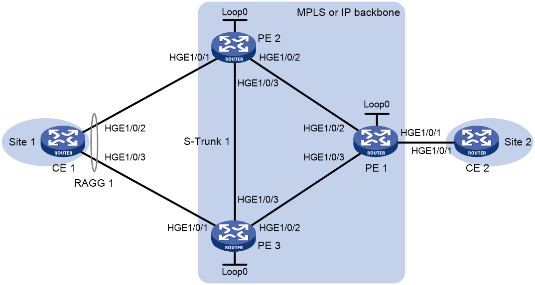
Network configuration
As shown in Figure 8:
· Configure MPLS L2VPN for CE 1 and CE 2 to communicate. CE 1 is dual-homed to PE 2 and PE 3.
· Configure S-Trunk on PE 2 and PE 3 to establish a multichassis aggregate link with CE 1. Configure PE 2 and PE 3 as the primary and secondary devices, respectively.
|
Device |
Interface |
IP address |
Device |
Interface |
IP address |
|
CE 1 |
RAGG 1 |
192.1.1.2/24 |
PE 1 |
Loop 0 |
1.1.1.1/32 |
|
PE 2 |
Loop 0 |
2.2.2.2/32 |
|
HGE1/0/2 |
10.1.1.1/24 |
|
|
HGE1/0/2 |
10.1.1.2/24 |
|
HGE1/0/3 |
10.1.2.1/24 |
|
|
HGE1/0/3 |
10.1.3.1/24 |
CE 2 |
HGE1/0/1 |
192.1.1.1/24 |
|
PE 3 |
Loop 0 |
3.3.3.3/32 |
|
|
|
|
|
HGE1/0/2 |
10.1.2.2/24 |
|
|
|
|
|
HGE1/0/3 |
10.1.3.2/24 |
|
|
|
Procedure
1. Assign IP addresses to interfaces as described in Table 1. (Details not shown.)
2. Configure OSPF for Layer 3 connectivity:
# Configure PE 1.
[PE1] ospf
[PE1-ospf-1] area 0
[PE1-ospf-1-area-0.0.0.0] network 10.1.1.0 0.0.0.255
[PE1-ospf-1-area-0.0.0.0] network 10.1.2.0 0.0.0.255
[PE1-ospf-1-area-0.0.0.0] network 1.1.1.1 0.0.0.0
[PE1-ospf-1-area-0.0.0.0] quit
[PE1-ospf-1] quit
# Configure PE 2.
[PE2] ospf
[PE2-ospf-1] area 0
[PE2-ospf-1-area-0.0.0.0] network 10.1.1.0 0.0.0.255
[PE2-ospf-1-area-0.0.0.0] network 10.1.3.0 0.0.0.255
[PE2-ospf-1-area-0.0.0.0] network 2.2.2.2 0.0.0.0
[PE2-ospf-1-area-0.0.0.0] quit
[PE2-ospf-1] quit
# Configure PE 3.
[PE3] ospf
[PE3-ospf-1] area 0
[PE3-ospf-1-area-0.0.0.0] network 10.1.2.0 0.0.0.255
[PE3-ospf-1-area-0.0.0.0] network 10.1.3.0 0.0.0.255
[PE3-ospf-1-area-0.0.0.0] network 3.3.3.3 0.0.0.0
[PE3-ospf-1-area-0.0.0.0] quit
[PE3-ospf-1] quit
3. Configure MPLS LSR IDs, and enable MPLS and LDP:
# Configure PE 1.
[PE1] mpls lsr-id 1.1.1.1
[PE1] mpls ldp
[PE1-ldp] quit
[PE1] interface hundredgige 1/0/2
[PE1-HundredGigE1/0/2] mpls enable
[PE1-HundredGigE1/0/2] mpls ldp enable
[PE1-HundredGigE1/0/2] quit
[PE1] interface hundredgige 1/0/3
[PE1-HundredGigE1/0/3] mpls enable
[PE1-HundredGigE1/0/3] mpls ldp enable
[PE1-HundredGigE1/0/3] quit
# Configure PE 2.
[PE2] mpls lsr-id 2.2.2.2
[PE2] mpls ldp
[PE2-ldp] quit
[PE2] interface hundredgige 1/0/2
[PE2-HundredGigE1/0/2] mpls enable
[PE2-HundredGigE1/0/2] mpls ldp enable
[PE2-HundredGigE1/0/2] quit
[PE2] interface hundredgige 1/0/3
[PE2-HundredGigE1/0/3] mpls enable
[PE2-HundredGigE1/0/3] mpls ldp enable
[PE2-HundredGigE1/0/3] quit
# Configure PE 3.
[PE3] mpls lsr-id 3.3.3.3
[PE3] mpls ldp
[PE3-ldp] quit
[PE3] interface hundredgige 1/0/2
[PE3-HundredGigE1/0/2] mpls enable
[PE3-HundredGigE1/0/2] mpls ldp enable
[PE3-HundredGigE1/0/2] quit
[PE3] interface hundredgige 1/0/3
[PE3-HundredGigE1/0/3] mpls enable
[PE3-HundredGigE1/0/3] mpls ldp enable
[PE3-HundredGigE1/0/3] quit
4. Enable L2VPN:
# Configure PE 1.
[PE1] l2vpn enable
# Configure PE 2.
[PE2] l2vpn enable
# Configure PE 3.
[PE3] l2vpn enable
5. Create a cross-connect group, configure the primary and backup PWs and bind them with ACs, and configure the dual receive feature for PW redundancy:
# Configure PE 1.
[PE1] xconnect-group vpna
[PE1-xcg-vpna] connection ldp
[PE1-xcg-vpna-ldp] ac interface hundredgige 1/0/1
[PE1-xcg-vpna-ldp-HundredGigE1/0/1] quit
[PE1-xcg-vpna-ldp] peer 2.2.2.2 pw-id 11
[PE1-xcg-vpna-ldp-2.2.2.2-11] backup-peer 3.3.3.3 pw-id 22
[PE1-xcg-vpna-ldp-2.2.2.2-11-backup] quit
[PE1-xcg-vpna-ldp-2.2.2.2-11] quit
[PE1-xcg-vpna-ldp] quit
[PE1-xcg-vpna] quit
# Configure PE 2.
[PE2] xconnect-group vpna
[PE2-xcg-vpna] connection ldp
[PE2-xcg-vpna-ldp] ac interface route-aggregation 1
[PE2-xcg-vpna-ldp-Route-Aggregation1] bypass-peer 3.3.3.3 pw-id 44 ac-bypass
[PE2-xcg-vpna-ldp-Route-Aggregation1- bypass] quit
[PE2-xcg-vpna-ldp-Route-Aggregation1] quit
[PE2-xcg-vpna-ldp] peer 1.1.1.1 pw-id 11
[PE2-xcg-vpna-ldp-1.1.1.1-11] bypass-peer 3.3.3.3 pw-id 33 pw-bypass
[PE2-xcg-vpna-ldp-1.1.1.1-11-bypass] quit
[PE2-xcg-vpna-ldp-1.1.1.1-11] quit
[PE2-xcg-vpna-ldp] quit
[PE2-xcg-vpna] quit
# Configure PE 2.
[PE3] xconnect-group vpna
[PE3-xcg-vpna] connection ldp
[PE3-xcg-vpna-ldp] ac interface route-aggregation 1
[PE3-xcg-vpna-ldp-Route-Aggregation1] bypass-peer 2.2.2.2 pw-id 33 ac-bypass
[PE3-xcg-vpna-ldp-Route-Aggregation1-bypass] quit
[PE3-xcg-vpna-ldp-Route-Aggregation1] quit
[PE3-xcg-vpna-ldp] peer 1.1.1.1 pw-id 22
[PE3-xcg-vpna-ldp-1.1.1.1-22] bypass-peer 2.2.2.2 pw-id 44 pw-bypass
[PE3-xcg-vpna-ldp-1.1.1.1-22-bypass] quit
[PE3-xcg-vpna-ldp-1.1.1.1-22] quit
[PE3-xcg-vpna-ldp] quit
[PE3-xcg-vpna] quit
6. Configure Ethernet link aggregation for CE 1 to be dual-homed to PE 2 and PE 3:
<CE1> system-view
[CE1] interface route-aggregation 1
[CE1-Route-Aggregation1] link-aggregation mode dynamic
[CE1-Route-Aggregation1] quit
[CE1] interface hundredgige 1/0/2
[CE1-HundredGigE1/0/2] port link-aggregation group 1
[CE1-HundredGigE1/0/2] quit
[CE1] interface hundredgige 1/0/3
[CE1-HundredGigE1/0/3] port link-aggregation group 1
[CE1-HundredGigE1/0/3] quit
7. Configure LACP system settings for PE 2 and PE 3 to be identified as one device:
# Configure PE 2.
[PE2] lacp system-priority 10
[PE2] lacp system-mac 1-1-1
[PE2] lacp system-number 1
# Configure PE 3.
[PE3] lacp system-priority 10
[PE3] lacp system-mac 1-1-1
[PE3] lacp system-number 2
8. Configure S-Trunk protocol packet parameters:
# Configure PE 2.
[PE2] s-trunk udp-port 2048
[PE2] s-trunk id 1
[PE2-s-trunk1] s-trunk role priority 100
[PE2-s-trunk1] s-trunk ip destination 10.1.3.2 source 10.1.3.1
[PE2-s-trunk1] quit
# Configure PE 3.
[PE3] s-trunk udp-port 2048
[PE3] s-trunk id 1
[PE3-s-trunk1] s-trunk role priority 200
[PE3-s-trunk1] s-trunk ip destination 10.1.3.1 source 10.1.3.2
[PE3-s-trunk1] quit
9. Create a static BFD session and associate it with smart trunk 1:
# Configure PE 2.
[PE2] bfd static bfd1 peer-ip 10.1.3.2 source-ip 10.1.3.1 discriminator local 1 remote 2
[PE2-bfd-static-session-bfd1] quit
[PE2] s-trunk id 1
[PE2-s-trunk1] s-trunk bfd-session bfd1
[PE2-s-trunk1] quit
# Configure PE 3.
[PE3] bfd static bfd1 peer-ip 10.1.3.1 source-ip 10.1.3.2 discriminator local 2 remote 1
[PE3-bfd-static-session-bfd1] quit
[PE3] s-trunk id 1
[PE3-s-trunk1] s-trunk bfd-session bfd1
[PE3-s-trunk1] quit
10. Configure smart trunk 1:
# Configure PE 2.
[PE2] interface route-aggregation 1
[PE2-Route-Aggregation1] link-aggregation mode dynamic
[PE2-Route-Aggregation1] s-trunk 1
[PE2-Route-Aggregation1] quit
[PE2] interface hundredgige 1/0/1
[PE2-HundredGigE1/0/1] port link-aggregation group 1
[PE2-HundredGigE1/0/1] quit
# Configure PE 3.
[PE3] interface route-aggregation 1
[PE3-Route-Aggregation1] link-aggregation mode dynamic
[PE3-Route-Aggregation1] s-trunk 1
[PE3-Route-Aggregation1] quit
[PE3] interface hundredgige 1/0/1
[PE3-HundredGigE1/0/1] port link-aggregation group 1
[PE3-HundredGigE1/0/1] quit
Verifying the configuration
# Verify that PE 1 has established LDP PWs with PE 2 and PE 3.
[PE1] display l2vpn pw
Flags: M - main, B - backup, BY - bypass, H - hub link, S - spoke link, N - no s
plit horizon
Total number of PWs: 2
1 up, 1 blocked, 0 down, 0 defect, 0 idle, 0 duplicate
Xconnect-group Name: vpna
Peer PW ID/Rmt Site In/Out Label Proto Flag Link ID State
2.2.2.2 11 65657/1151 LDP M 0 Up
3.3.3.3 22 65656/1151 LDP B 0 Blocked
The output shows that the PW to PE 2 is the primary PW and the PW to PE 3 is the backup PW.
# Verify that PE 2 and PE 3 have established two LDP PWs between them.
[PE2] display l2vpn pw
Flags: M - main, B - backup, E - ecmp, BY - bypass, H - hub link, S - spoke link
N - no split horizon, A - administration, ABY - ac-bypass
PBY - pw-bypass
Total number of PWs: 3
1 up, 2 blocked, 0 down, 0 defect, 0 idle, 0 duplicate
Xconnect-group Name: 1
Peer PWID/RmtSite/SrvID In/Out Label Proto Flag Link ID State
3.3.3.3 44 24125/24127 LDP ABY 0 Blocked
1.1.1.1 11 24129/24124 LDP M 1 Up
3.3.3.3 33 24128/24128 LDP PBY 1 Blocked
[PE3] display l2vpn pw
Flags: M - main, B - backup, E - ecmp, BY - bypass, H - hub link, S - spoke link
N - no split horizon, A - administration, ABY - ac-bypass
PBY - pw-bypass
Total number of PWs: 3
2 up, 1 blocked, 0 down, 0 defect, 0 idle, 0 duplicate
Xconnect-group Name: 1
Peer PWID/RmtSite/SrvID In/Out Label Proto Flag Link ID State
2.2.2.2 33 24128/24128 LDP ABY 0 Up
1.1.1.1 22 24129/24123 LDP M 1 Up
2.2.2.2 44 24127/24125 LDP PBY 1 Blocked
# Verify that the BFD session between PE 2 and PE 3 is up.
[PE2] display bfd session
Total sessions: 1 Up sessions: 1 Init mode: Active
IPv4 static session working in control packet mode:
LD/RD SourceAddr DestAddr State Holdtime Interface
1/2 10.1.3.1 10.1.3.2 Up 1870ms N/A
[PE3] display bfd session
Total sessions: 1 Up sessions: 1 Init mode: Active
IPv4 static session working in control packet mode:
LD/RD SourceAddr DestAddr State Holdtime Interface
2/1 10.1.3.2 10.1.3.1 Up 1947ms N/A
# Verify that HundredGigE 1/0/2 is a Selected aggregation member port on CE 1.
[CE1] display link-aggregation verbose route-aggregation 1
Loadsharing Type: Shar -- Loadsharing, NonS -- Non-Loadsharing
Port Status: S -- Selected, U -- Unselected, I -- Individual
Port: A -- Auto
Flags: A -- LACP_Activity, B -- LACP_Timeout, C -- Aggregation,
D -- Synchronization, E -- Collecting, F -- Distributing,
G -- Defaulted, H -- Expired
Aggregate Interface: Route-Aggregation1
Aggregation Mode: Dynamic
Loadsharing Type: Shar
System ID: 0x8000, 90e7-10f9-5000
Local:
Port Status Priority Index Oper-Key Flag
HGE1/0/2 S 32768 1 1 {ACDEF}
HGE1/0/3 U 32768 2 1 {ACD}
Remote:
Actor Priority Index Oper-Key SystemID Flag
HGE1/0/2 32768 16385 24577 0xa , 0001-0001-0001 {ACDEF}
HGE1/0/3 32768 32769 24577 0xa , 0001-0001-0001 {AC}
# Verify that PE 2 and PE 3 are the primary and secondary S-Trunk member devices, respectively.
[PE2] display s-trunk verbose 1
Trunk-wide info and statistics
S-Trunk ID: 1
Revert: Enabled Revert-delay(s): 120
Local bridge MAC: 00fc-3423-d800 Peer bridge MAC: 84d9-3125-7800
Local priority: 32768 Peer priority: 32768
DevRole (Trigger): Primary (PRIORITY)
DestIP: 10.1.3.2 SrcIP: 10.1.3.1
Local hello interval(100ms): 100 Local hello timeout(100ms): 2000
InStrunkPDUs: 16571 OutStrunkPDUs: 16603
InDrops: 0 OutDrops: 36
Peer hello interval(100ms): 100 Peer hello timeout(100ms): 2000
Sequence number check: Disabled
BFD-Session: bfd1
VPN instance: -
Description: -
Trunk member info
Local LinkState ConfigRole OperRole (Trigger) Peer
RAGG1 UP auto Primary (PEER_MEMBER_DOWN) RAGG1
[PE3] display s-trunk verbose 1
Trunk-wide info and statistics
S-Trunk ID: 1
Revert: Enabled Revert-delay(s): 120
Local bridge MAC: 84d9-3125-7800 Peer bridge MAC: 00fc-3423-d800
Local priority: 32768 Peer priority: 32768
DevRole (Trigger): Secondary (PRIORITY)
DestIP: 10.1.3.1 SrcIP: 10.1.3.2
Local hello interval(100ms): 100 Local hello timeout(100ms): 2000
InStrunkPDUs: 16580 OutStrunkPDUs: 16621
InDrops: 0 OutDrops: 37
Peer hello interval(100ms): 100 Peer hello timeout(100ms): 2000
Sequence number check: Disabled
BFD-Session: bfd1
VPN instance: -
Description: -
Trunk member info
Local LinkState ConfigRole OperRole (Trigger) Peer
RAGG1 DOWN auto Secondary (PEER_MEMBER_UP) RAGG1