- Table of Contents
-
- 10-High Availability Configuration Guide
- 00-Preface
- 01-Ethernet OAM configuration
- 02-CFD configuration
- 03-DLDP configuration
- 04-RRPP configuration
- 05-ERPS configuration
- 06-Smart Link configuration
- 07-Monitor Link configuration
- 08-Error code detection configuration
- 09-VRRP configuration
- 10-BFD configuration
- 11-Track configuration
- 12-Process placement configuration
- 13-S-Trunk configuration
- Related Documents
-
| Title | Size | Download |
|---|---|---|
| 07-Monitor Link configuration | 124.25 KB |
Contents
Restrictions and guidelines: Monitor Link configuration
Monitor Link tasks at a glance
Enabling Monitor Link globally
Enabling Monitor Link for a monitor link group
Configuring the name of a monitor link group
Configuring monitor link group member interfaces
Configuring monitor link group member interfaces in monitor link group view
Configuring monitor link group member interfaces in interface view
Configuring the uplink interface threshold for triggering monitor link group state switchover
Configuring the switchover delay for the downlink interfaces in a monitor link group
Display and maintenance commands for Monitor Link
Configuring Monitor Link
About Monitor Link
Monitor Link associates the state of downlink interfaces with the state of uplink interfaces in a monitor link group. When Monitor Link shuts down the downlink interfaces because of an uplink failure, the downstream device changes connectivity to another link.
Figure 1 Monitor Link application scenario
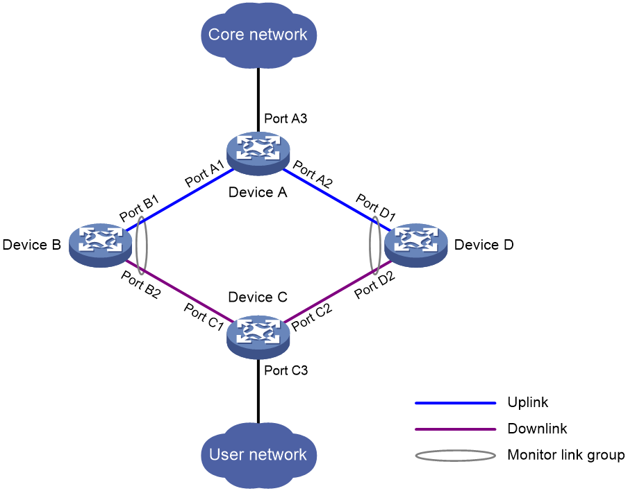
Monitor Link concepts
A monitor link group contains uplink and downlink interfaces. An interface can belong to only one monitor link group.
· Uplink interfaces are the monitored interfaces.
· Downlink interfaces are the monitoring interfaces.
As shown in Figure 1:
· Port B1 and Port B2 of Device B form a monitor link group. Port B1 is an uplink interface, and Port B2 is a downlink interface.
· Port D1 and Port D2 of Device D form another monitor link group. Port D1 is an uplink interface, and Port D2 is a downlink interface.
Interface collaboration mode
A monitor link group works independently of other monitor link groups. A monitor link group can associate the state of downlink interfaces with the state of uplink interfaces in the following ways:
· When a monitor link group does not contain any uplink interface or all its uplink interfaces are down, the monitor link group goes down. It forces all downlink interfaces down at the same time. When any uplink interface comes up, the monitor link group comes up and brings up all the downlink interfaces.
· When the total weight of all uplink interfaces in down state is greater than or equal to the weight of a downlink interface, the downlink interface goes down. Other downlink interfaces are not affected. When the total weight is smaller than the weight of the downlink interface, the downlink interface comes back up.
Restrictions and guidelines: Monitor Link configuration
Follow these restrictions and guidelines when you configure Monitor Link:
· Do not manually shut down or bring up the downlink interfaces in a monitor link group.
· To avoid frequent state changes of downlink interfaces in the event that uplink interfaces in the monitor link group flap, you can configure a switchover delay. The switchover delay is the time that the downlink interfaces wait before they come up following an uplink interface.
Monitor Link tasks at a glance
To configure Monitor Link, perform the following tasks:
· Enabling Monitor Link globally
· Creating a monitor link group
· Enabling Monitor Link for a monitor link group
· (Optional.) Configuring the name of a monitor link group
· Configuring monitor link group member interfaces
· (Optional.) Configuring the uplink interface threshold for triggering monitor link group state switchover
· (Optional.) Configuring the switchover delay for the downlink interfaces in a monitor link group
Enabling Monitor Link globally
About this task
A monitor link group can operate only after you enable Monitor Link both globally and for the monitor link group. When you disable Monitor Link globally or for a monitor link group, the monitor link group cannot operate and the downlink interfaces brought down by it resume their original states.
Procedure
1. Enter system view.
system-view
2. Enable Monitor Link globally.
undo monitor-link disable
By default, Monitor Link is enabled globally.
Creating a monitor link group
1. Enter system view.
system-view
2. Create a monitor link group and enter monitor link group view.
monitor-link group group-id
Enabling Monitor Link for a monitor link group
About this task
A monitor link group can operate only after you enable Monitor Link both globally and for the monitor link group. When you disable Monitor Link globally or for a monitor link group, the monitor link group cannot operate and the downlink interfaces brought down by it resume their original states.
Procedure
1. Enter system view.
system-view
2. Create a monitor link group and enter its view.
monitor-link group group-id
3. Enable Monitor Link for the monitor link group.
undo monitor-link disable
By default, Monitor Link is enabled for a monitor link group.
Configuring the name of a monitor link group
Restrictions and guidelines
Different monitor link groups cannot have the same group name.
Procedure
1. Enter system view.
system-view
2. Enter monitor link group view.
monitor-link group group-id
3. Configure the name of the monitor link group.
group-name name
By default, a monitor link group is named groupXX, where XX is the monitor link group ID. For example, monitor link group 1 is named group1 by default.
Configuring monitor link group member interfaces
Restrictions and guidelines
· An interface can be assigned to only one monitor link group.
· To avoid undesired down/up state changes on the downlink interfaces, configure uplink interfaces before you configure downlink interfaces.
· If you have configured an interface as the downlink interface of a monitor link group, do not configure its subinterfaces as the uplink interfaces of any monitor link group. Otherwise, the Monitor Link operation might be interrupted.
· The state of subinterfaces is associated with the state of the interface. Do not add the interface and its subinterfaces to the same monitor link group. Otherwise, the monitor link group performance might be affected.
· If you have configured a Selected port of an aggregation group as the downlink interface of a monitor link group, do not configure an Unselected port of the aggregation group as the uplink interface of the monitor link group.
· Do not add an aggregate interface and its member ports to the same monitor link group. Otherwise, the Monitor Link operation might be interrupted.
· You can configure member interfaces for a monitor link group in monitor link group view or interface view. Configurations made in these views have the same effect.
The configuration is supported by the following interfaces:
¡ Layer 2 Ethernet interfaces and Layer 2 aggregate interfaces.
¡ Layer 3 Ethernet interfaces/subinterfaces.
¡ Layer 3 aggregate interfaces/subinterfaces.
· A monitor link group forces downlink interfaces down if either of the following conditions exists:
¡ The number of uplink interfaces in up state in the monitor link group is smaller than the uplink interface threshold. In this case, the monitor link group shuts down all downlink interfaces.
¡ The total weight of all uplink interfaces in down state is greater than or equal to the weight of certain downlink interfaces in the monitor link group. In this case, the monitor link group shuts down only these downlink interfaces.
· As a best practice, set a downlink interface weight to be smaller than or equal to the total weight of all uplink interfaces in a monitor link group. Without this setting, Monitor Link cannot shut down the downlink interface based on uplink interface state change.
· To avoid downlink interface flapping, you must disable Monitor Link before performing the following tasks on a member interface in a monitor link group:
¡ Remove the member interface from the monitor link group.
¡ Remove and then reinsert the card where the member interface resides.
¡ Change the link mode of the member interface to Layer 2 or Layer 3 mode by using the port link-mode command.
Configuring monitor link group member interfaces in monitor link group view
1. Enter system view.
system-view
2. Enter monitor link group view.
monitor-link group group-id
3. Configure member interfaces for the monitor link group.
port interface-type { interface-number | interface-number.subnumber } { downlink | uplink } [ weight weight-value ]
By default, no member interfaces exist in a monitor link group.
Configuring monitor link group member interfaces in interface view
1. Enter system view.
system-view
2. Enter interface view or subinterface view.
interface interface-type { interface-number | interface-number.subnumber }
3. Configure the interface as a member of a monitor link group.
port monitor-link group group-id { downlink | uplink } [ weight weight-value ]
By default, the interface is not a monitor link group member.
Configuring the uplink interface threshold for triggering monitor link group state switchover
1. Enter system view.
system-view
2. Enter monitor link group view.
monitor-link group group-id
3. Configure the uplink interface threshold for triggering monitor link group state switchover.
uplink up-port-threshold number-of-port
By default, the uplink interface threshold for triggering monitor link group state switchover is 1.
Configuring the switchover delay for the downlink interfaces in a monitor link group
1. Enter system view.
system-view
2. Enter monitor link group view.
monitor-link group group-id
3. Configure the switchover delay for the downlink interfaces in the monitor link group.
downlink up-delay delay
By default, the switchover delay is 0 seconds. The downlink interfaces come up as soon as an uplink interface comes up.
Display and maintenance commands for Monitor Link
Execute the display command in any view:
|
Task |
Command |
|
Display monitor link group information. |
display monitor-link group { group-id | all } |
Monitor Link configuration examples
Example: Configuring Monitor Link
Network configuration
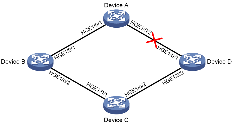
As shown in Figure 2:
· Device C is a Smart Link device, and Device A, Device B, and Device D are associated devices. Traffic of VLANs 1 through 30 on Device C is dual-uplinked to Device A through a smart link group.
· Implement dual uplink backup on Device C. When the link between Device A and Device B (or Device D) fails, Device C can detect the link fault. It then performs uplink switchover in the smart link group.
For more information about Smart Link, see "Configuring Smart Link."
Procedure
|
|
IMPORTANT: · By default, interfaces on the device are disabled (in ADM or Administratively Down state). To have an interface operate, you must use the undo shutdown command to enable that interface. · By default, interfaces on the device operate in Layer 3 mode. In this example, the interfaces must operate in Layer 2 mode. You can use the port link-mode command to change the link mode of an interface. |
1. Configure Device C:
# Create VLANs 1 through 30.
<DeviceC> system-view
[DeviceC] vlan 1 to 30
# Map these VLANs to MSTI 1.
[DeviceC] stp region-configuration
[DeviceC-mst-region] instance 1 vlan 1 to 30
# Activate MST region configuration.
[DeviceC-mst-region] active region-configuration
[DeviceC-mst-region] quit
# Shut down HundredGigE 1/0/1.
[DeviceC] interface hundredgige 1/0/1
[DeviceC-HundredGigE1/0/1] shutdown
# Disable the spanning tree feature on the interface.
[DeviceC-HundredGigE1/0/1] undo stp enable
# Configure the interface as a trunk port.
[DeviceC-HundredGigE1/0/1] port link-type trunk
# Assign the interface to VLANs 1 through 30.
[DeviceC-HundredGigE1/0/1] port trunk permit vlan 1 to 30
[DeviceC-HundredGigE1/0/1] quit
# Configure HundredGigE 1/0/2 in the same way HundredGigE 1/0/1 is configured.
[DeviceC] interface hundredgige 1/0/2
[DeviceC-HundredGigE1/0/2] shutdown
[DeviceC-HundredGigE1/0/2] undo stp enable
[DeviceC-HundredGigE1/0/2] port link-type trunk
[DeviceC-HundredGigE1/0/2] port trunk permit vlan 1 to 30
[DeviceC-HundredGigE1/0/2] quit
# Create smart link group 1, and configure all the VLANs mapped to MSTI 1 as the protected VLANs for smart link group 1.
[DeviceC] smart-link group 1
[DeviceC-smlk-group1] protected-vlan reference-instance 1
# Configure HundredGigE 1/0/1 as the primary port and HundredGigE 1/0/2 as the secondary port for smart link group 1.
[DeviceC-smlk-group1] port hundredgige 1/0/1 primary
[DeviceC-smlk-group1] port hundredgige 1/0/2 secondary
# Enable the smart link group to transmit flush messages.
[DeviceC-smlk-group1] flush enable
[DeviceC-smlk-group1] quit
# Bring up HundredGigE 1/0/1 and HundredGigE 1/0/2.
[DeviceC] interface hundredgige 1/0/1
[DeviceC-HundredGigE1/0/1] undo shutdown
[DeviceC-HundredGigE1/0/1] quit
[DeviceC] interface hundredgige 1/0/2
[DeviceC-HundredGigE1/0/2] undo shutdown
[DeviceC-HundredGigE1/0/2] quit
2. Configure Device A:
# Create VLANs 1 through 30.
<DeviceA> system-view
[DeviceA] vlan 1 to 30
# Configure HundredGigE 1/0/1 as a trunk port.
[DeviceA] interface hundredgige 1/0/1
[DeviceA-HundredGigE1/0/1] port link-type trunk
# Assign the interface to VLANs 1 through 30.
[DeviceA-HundredGigE1/0/1] port trunk permit vlan 1 to 30
# Enable flush message receiving on the interface.
[DeviceA-HundredGigE1/0/1] smart-link flush enable
[DeviceA-HundredGigE1/0/1] quit
# Configure HundredGigE 1/0/2 in the same way HundredGigE 1/0/1 is configured.
[DeviceA] interface hundredgige 1/0/2
[DeviceA-HundredGigE1/0/2] port link-type trunk
[DeviceA-HundredGigE1/0/2] port trunk permit vlan 1 to 30
[DeviceA-HundredGigE1/0/2] smart-link flush enable
[DeviceA-HundredGigE1/0/2] quit
3. Configure Device B:
# Create VLANs 1 through 30.
<DeviceB> system-view
[DeviceB] vlan 1 to 30
# Configure HundredGigE 1/0/1 as a trunk port.
[DeviceB] interface hundredgige 1/0/1
[DeviceB-HundredGigE1/0/1] port link-type trunk
# Assign the interface to VLANs 1 through 30.
[DeviceB-HundredGigE1/0/1] port trunk permit vlan 1 to 30
# Enable flush message receiving on the interface.
[DeviceB-HundredGigE1/0/1] smart-link flush enable
[DeviceB-HundredGigE1/0/1] quit
# Disable the spanning tree feature on HundredGigE 1/0/2.
[DeviceB] interface hundredgige 1/0/2
[DeviceB-HundredGigE1/0/2] undo stp enable
# Configure the interface as a trunk port.
[DeviceB-HundredGigE1/0/2] port link-type trunk
# Assign the interface to VLANs 1 through 30.
[DeviceB-HundredGigE1/0/2] port trunk permit vlan 1 to 30
# Enable flush message receiving on the interface.
[DeviceB-HundredGigE1/0/2] smart-link flush enable
[DeviceB-HundredGigE1/0/2] quit
# Create monitor link group 1.
[DeviceB] monitor-link group 1
# Configure HundredGigE 1/0/1 as an uplink interface for monitor link group 1.
[DeviceB-mtlk-group1] port hundredgige 1/0/1 uplink
# Configure HundredGigE 1/0/2 as a downlink interface for monitor link group 1.
[DeviceB-mtlk-group1] port hundredgige 1/0/2 downlink
[DeviceB-mtlk-group1] quit
4. Configure Device D:
# Create VLANs 1 through 30.
<DeviceD> system-view
[DeviceD] vlan 1 to 30
# Configure HundredGigE 1/0/1 as a trunk port.
[DeviceD] interface hundredgige 1/0/1
[DeviceD-HundredGigE1/0/1] port link-type trunk
# Assign the interface to VLANs 1 through 30.
[DeviceD-HundredGigE1/0/1] port trunk permit vlan 1 to 30
# Enable flush message receiving on the interface.
[DeviceD-HundredGigE1/0/1] smart-link flush enable
[DeviceD-HundredGigE1/0/1] quit
# Disable the spanning tree feature on HundredGigE 1/0/2.
[DeviceD] interface hundredgige 1/0/2
[DeviceD-HundredGigE1/0/2] undo stp enable
# Configure the interface as a trunk port.
[DeviceD-HundredGigE1/0/2] port link-type trunk
# Assign the interface to VLANs 1 through 30.
[DeviceD-HundredGigE1/0/2] port trunk permit vlan 1 to 30
# Enable flush message receiving on the interface.
[DeviceD-HundredGigE1/0/2] smart-link flush enable
[DeviceD-HundredGigE1/0/2] quit
# Create monitor link group 1.
[DeviceD] monitor-link group 1
# Configure HundredGigE 1/0/1 as an uplink interface for monitor link group 1.
[DeviceD-mtlk-group1] port hundredgige 1/0/1 uplink
# Configure HundredGigE 1/0/2 as a downlink interface for monitor link group 1.
[DeviceD-mtlk-group1] port hundredgige 1/0/2 downlink
[DeviceD-mtlk-group1] quit
Verifying the configuration
# When HundredGigE 1/0/2 on Device A goes down because of a link fault, verify information about monitor link group 1 on Device B.
[DeviceB] display monitor-link group 1
Monitor link group 1 information:
Group name : group1
Group status : UP
Downlink up-delay: 0(s)
Last-up-time : 16:38:26 2012/4/21
Last-down-time : 16:37:20 2012/4/21
Up-port-threshold: 1
Member Role Status Weight
HGE1/0/1 UPLINK UP 10
HGE1/0/2 DOWNLINK UP 0(default)
# Verify information about monitor link group 1 on Device D.
[DeviceD] display monitor-link group 1
Monitor link group 1 information:
Group name : group1
Group status : DOWN
Downlink up-delay: 0(s)
Last-up-time : 16:37:20 2012/4/21
Last-down-time : 16:38:26 2012/4/21
Up-port-threshold: 1
Member Role Status Weight
HGE1/0/1 UPLINK DOWN 10
HGE1/0/2 DOWNLINK DOWN (Monitor Link) 0(default)