- Table of Contents
-
- 17-Network Management and Monitoring Configuration Guide
- 00-Preface
- 01-Information center configuration
- 02-Flow log configuration
- 03-Fast log output configuration
- 04-NetStream configuration
- 05-Mirroring configuration
- 06-Packet capture configuration
- 07-NQA configuration
- 08-Track configuration
- 09-BFD configuration
- 10-Monitor Link configuration
- 11-Smart Link configuration
- 12-Interface backup configuration
- 13-Interface collaboration configuration
- 14-System maintenance and debugging configuration
- 15-NTP configuration
- 16-EAA configuration
- 17-Process monitoring and maintenance configuration
- 18-NETCONF configuration
- 19-CWMP configuration
- 20-SNMP configuration
- 21-RMON configuration
- 22-Event MIB configuration
- 23-Process placement configuration
- Related Documents
-
| Title | Size | Download |
|---|---|---|
| 02-Flow log configuration | 248.38 KB |
Contents
Specifying a flow log export destination
Restrictions and guidelines for flow log export destination configuration
Specifying a log host as the flow log export destination
Specifying the information center as the flow log export destination
Configuring the flow log version
Specifying a source IP address for flow log packets
Configuring the timestamp of flow log entries
Enabling load balancing for flow log entries
Configuring flow log host groups
Prerequisites for log host group configuration
Configuring an IPv4 flow log host group
Configuring an IPv6 flow log host group
Display and maintenance commands for flow log
Flow log configuration examples
Example: Configuring NAT flow log export
Example: Configuring session flow log export
Example: Configuring NAT flow log export to a flow log host group
Appendix A Flow message fields
AFT IPv6-to-IPv4 flow message fields
AFT IPv4-to-IPv6 flow message fields
Configuring flow log
About flow log
Flow log records session information based on flows.
A flow log entry might contain the following information about a flow:
· Network access quintuple information (source IP address, destination IP address, source port, destination port, and protocol number).
· Statistics about sent and received packet statistics.
· Flow-based link selection information.
Flow log export
You can export flow log entries in the following methods:
· Export flow log entries to log hosts. Flow log entries are sent as binary characters in UDP. One UDP packet can contain multiple log entries.
· Export flow log entries to the information center. Flow log entries are converted to syslog entries in ASCII format, with the informational severity level. The information center specifies the output destinations for the logs. Available output destinations include the console, log host, and log file. For more information about the information center, see "Configuring the information center."
Log entries in ASCII format are human readable. However, the log data volume is higher in ASCII format than in binary format.
Flow log packet
A flow log packet is a UDP packet, whose data field contains a message header and a message body, as shown in Figure 1. A message body can contain information about one message or multiple messages of the same type.
Figure 1 Flow log packet
![]()
Flow log supports message types of various service modules. For message header and body descriptions for different message types, see "Appendix A Flow message fields."
Flow log tasks at a glance
To configure flow log, perform the following tasks:
2. Specifying a flow log export destination
Choose one of the following tasks:
¡ Specifying a log host as the flow log export destination
¡ Specifying the information center as the flow log export destination
3. (Optional.) Configuring the flow log version
4. (Optional.) Specifying a source IP address for flow log packets
5. (Optional.) Configuring the timestamp of flow log entries
6. (Optional.) Enabling load balancing for flow log entries
7. (Optional.) Configuring flow log host groups
Enabling flow log output
Before you configure the flow log feature, you must first enable flow log output as follows:
· To enable NAT logging, execute the nat log enable command. For more information, see Layer 3—IP Services Command Reference.
· To enable AFT logging, execute the aft log enable command. For more information, see Layer 3—IP Services Command Reference.
· To enable load balancing NAT logging, execute the loadbalance log enable nat command. For more information, see Load Balancing Command Reference.
Specifying a flow log export destination
Restrictions and guidelines for flow log export destination configuration
You can export flow log entries to a log host or the information center, but not both. If you configure both methods, the system exports flow log entries to the information center.
Flow log entries exported to the information center has the informational severity level.
Specifying a log host as the flow log export destination
1. Enter system view.
system-view
2. Specify a log host as the destination for flow log export.
userlog flow export [ vpn-instance vpn-instance-name ] host { hostname | ipv4-address | ipv6 ipv6-address } port udp-port
By default, no log hosts are specified.
You can specify multiple log hosts.
Specifying the information center as the flow log export destination
1. Enter system view.
system-view
2. Specify the information center as the destination for flow log export.
userlog flow syslog
By default, flow log entries are not exported to the information center.
Configuring the flow log version
Restrictions and guidelines
Make sure the specified flow log version is supported on the log host.
If you configure the flow log version multiple times, the most recent configuration takes effect.
Procedure
1. Enter system view.
system-view
2. Configure the flow log version.
userlog flow export version version-number
The default flow log version is 1.0.
Specifying a source IP address for flow log packets
About this task
By default, the source IP address for flow log packets is the IP address of their outgoing interface. For the log hosts to filter log entries by log sender, specify a source IP address for all flow log packets.
Restrictions and guidelines
As a best practice, use a Loopback interface's address as the source IP address for flow log packets. A Loopback interface is always up. The setting avoids export failure on interfaces that might go down.
Procedure
1. Enter system view.
system-view
2. Specify a source IP address for flow log packets.
userlog flow export source-ip { ipv4-address | ipv6 ipv6-address }
By default, the source IP address for flow log packets is the IP address of their outgoing interface.
Configuring the timestamp of flow log entries
About this task
The device uses either the local time or the UTC time in the timestamp of flow logs.
· UTC time—Standard Greenwich Mean Time (GMT).
· Local time—Standard GMT plus or minus the time zone offset.
The time zone offset can be configured by using the clock timezone command. For more information, see device management in Fundamentals Command Reference.
Procedure
1. Enter system view.
system-view
2. Configure the device to use the local time in the flow log timestamp.
userlog flow export timestamp localtime
By default, the UTC time is used in the flow log timestamp.
Enabling load balancing for flow log entries
About this task
By default, the device sends a copy of each flow log entry to all configured log hosts. When one log host fails, other log hosts still have complete flow log entries.
In load balancing mode, flow log entries are distributed among log hosts based on the source IP addresses (before NAT) that are recorded in the entries. The flow log entries generated for the same source IP address are sent to the same log host.
Restrictions and guidelines
In load balancing mode, flow logs are load balanced among all configured log hosts, regardless of whether the log hosts are reachable. If a log host is unreachable, the flow logs sent to it will be lost.
Procedure
1. Enter system view.
system-view
2. Enable load balancing for flow log entries.
userlog flow export load-balancing
By default, load balancing is disabled.
Configuring flow log host groups
About flow log host group
By default, the device sends a copy of each flow log entry to all available log hosts. To filter logs and reduce the log sending and processing workload of the device, configure the flow log host group feature.
The flow log host group feature allows you to classify flow log hosts into groups and specify an ACL for each group. A flow log matches a log host group if it matches the group's ACL, and it is sent only to the log hosts in the matching group.
If a flow log matches multiple log host groups, the device sends the log to the group that comes first in alphabetical order of the matching group names.
If a flow log does not match any log host groups, the device ignores the log host group configuration and sends the log to all configured log hosts.
If load balancing is enabled, flow logs sent to a log host group will be load-shared among the log hosts in the group. Flow logs generated for the same source IP address are sent to the same log host.
Prerequisites for log host group configuration
Before you configure flow log host groups, complete the following tasks:
· Configure the ACLs to be used by the flow log host groups.
· Use the userlog flow export host command to configure the log hosts to be assigned to the flow log host groups.
Configuring an IPv4 flow log host group
1. Enter system view.
system-view
2. Create an IPv4 flow log host group and enter its view.
userlog host-group host-group-name acl { name acl-name | number acl-number }
By default, no IPv4 flow log host groups exist.
3. Assign an IPv4 log host to the flow log host group.
userlog host-group [ vpn-instance vpn-instance-name ] host flow { hostname | ipv4-address }
By default, an IPv4 flow log host group does not contain any log hosts.
Configuring an IPv6 flow log host group
1. Enter system view.
system-view
2. Create an IPv6 flow log host group and enter its view.
userlog host-group ipv6 host-group-name acl { name acl-name | number acl-number }
By default, no IPv6 flow log host groups exist.
3. Assign an IPv6 log host to the flow log host group.
userlog host-group [ vpn-instance vpn-instance-name ] host flow ipv6 { hostname | ipv6-address }
By default, an IPv6 flow log host group does not contain any log hosts.
Display and maintenance commands for flow log
Execute display commands in any view.
|
Task |
Command |
|
Display flow log configuration and statistics. |
display userlog export |
|
Display flow log host group information. |
display userlog host-group [ ipv6 ] [ host-group-name ] |
|
Clear flow log statistics. |
reset userlog flow export |
Flow log configuration examples
Example: Configuring NAT flow log export
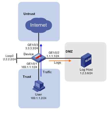
Network configuration
As shown in Figure 2, configure flow log on the device to send flow log entries generated for the user to the log host.
Procedure
1. Assign IP addresses to interfaces.
# Assign an IP address to interface GigabitEthernet 1/0/1.
<Device> system-view
[Device] interface loopback 0
[Device-LoopBack0] ip address 2.2.2.2 255.255.255.0
[Device-LoopBack0] quit
[Device] interface gigabitethernet 1/0/1
[Device-GigabitEthernet1/0/1] ip address 169.1.1.1 255.255.255.0
[Device-GigabitEthernet1/0/1] quit
# Assign IP addresses to other interfaces in the same way. (Details not shown.)
2. Configure settings for routing.
This example configures static routes, and the next hops in the routes are 1.1.1.2 and 3.3.3.1, respectively.
[Device] ip route-static 1.2.3.0 24 1.1.1.2
[Device] ip route-static 0.0.0.0 0 3.3.3.1
3. Add interfaces to security zones.
[Device] security-zone name trust
[Device-security-zone-Trust] import interface gigabitethernet 1/0/1
[Device-security-zone-Trust] quit
[Device] security-zone name dmz
[Device-security-zone-DMZ] import interface gigabitethernet 1/0/2
[Device-security-zone-DMZ] quit
[Device] security-zone name untrust
[Device-security-zone-Untrust] import interface gigabitethernet 1/0/3
[Device-security-zone-Untrust] quit
4. Configure a security policy:
# Configure a rule named loglocalout to allow the device to send log packets to the log host.
[Device] security-policy ip
[Device-security-policy-ip] rule name loglocalout
[Device-security-policy-ip-1-loglocalout] source-zone local
[Device-security-policy-ip-1-loglocalout] destination-zone dmz
[Device-security-policy-ip-1-loglocalout] source-ip-host 2.2.2.2
[Device-security-policy-ip-1-loglocalout] destination-ip-host 1.2.3.6
[Device-security-policy-ip-1-loglocalout] action pass
[Device-security-policy-ip-1-loglocalout] quit
[Device-security-policy-ip] quit
# Configure a rule named trust-untrust to all the user to access the Internet.
[Device-security-policy-ip] rule name trust-untrust
[Device-security-policy-ip-3-trust-untrust] source-zone trust
[Device-security-policy-ip-3-trust-untrust] destination-zone untrust
[Device-security-policy-ip-3-trust-untrust] source-ip-subnet 169.1.1.0 24
[Device-security-policy-ip-3-trust-untrust] action pass
[Device-security-policy-ip-3-trust-untrust] quit
[Device-security-policy-ip] quit
5. Configure flow log settings:
# Enable NAT logging for session establishment events, session removal events, and active flows. Set the flow log version to 3.0.
[Device] nat log enable
[Device] nat log flow-begin
[Device] nat log flow-end
[Device] nat log flow-active 10
[Device] userlog flow export version 3
# Specify the log host at 1.2.3.6 as the destination for flow log export, set the UDP port number to 2000, and specify 2.2.2.2 as the source IP address for flow log packets.
[Device] userlog flow export host 1.2.3.6 port 2000
[Device] userlog flow export source-ip 2.2.2.2
Verifying the configuration
# Display the flow log configuration and statistics.
[Device] display userlog export
Flow:
Export flow log as UDP Packet.
Version: 3.0
Source ipv4 address: 2.2.2.2
Log load balance function: Disabled
Local time stamp: Disabled
Number of log hosts: 1
Log host 1:
Host/Port: 1.2.3.6/2000
Total logs/UDP packets exported: 112/87
Example: Configuring session flow log export
Network configuration
As shown in Figure 3, configure flow log on the device to send session flow log entries generated for the user to the log host.

Procedure
1. Assign IP addresses to interfaces.
# Assign an IP address to interface GigabitEthernet 1/0/1.
<Device> system-view
[Device] interface loopback 0
[Device-LoopBack0] ip address 2.2.2.2 255.255.255.0
[Device-LoopBack0] quit
[Device] interface gigabitethernet 1/0/1
[Device-GigabitEthernet1/0/1] ip address 169.1.1.1 255.255.255.0
[Device-GigabitEthernet1/0/1] quit
# Assign IP addresses to other interfaces in the same way. (Details not shown.)
2. Configure settings for routing.
This example configures static routes, and the next hops in the routes are 1.1.1.2 and 3.3.3.1, respectively.
[Device] ip route-static 1.2.3.0 24 1.1.1.2
[Device] ip route-static 0.0.0.0 0 3.3.3.1
3. Add interfaces to security zones.
[Device] security-zone name trust
[Device-security-zone-Trust] import interface gigabitethernet 1/0/1
[Device-security-zone-Trust] quit
[Device] security-zone name dmz
[Device-security-zone-DMZ] import interface gigabitethernet 1/0/2
[Device-security-zone-DMZ] quit
[Device] security-zone name untrust
[Device-security-zone-Untrust] import interface gigabitethernet 1/0/3
[Device-security-zone-Untrust] quit
4. Configure a security policy.
# Configure a rule named loglocalout to allow the device to send log packets to the log host.
[Device] security-policy ip
[Device-security-policy-ip] rule name loglocalout
[Device-security-policy-ip-1-loglocalout] source-zone local
[Device-security-policy-ip-1-loglocalout] destination-zone dmz
[Device-security-policy-ip-1-loglocalout] source-ip-host 2.2.2.2
[Device-security-policy-ip-1-loglocalout] destination-ip-host 1.2.3.6
[Device-security-policy-ip-1-loglocalout] action pass
[Device-security-policy-ip-1-loglocalout] quit
[Device-security-policy-ip] quit
# Configure a rule named trust-untrust to allow the user to access the Internet.
[Device-security-policy-ip] rule name trust-untrust
[Device-security-policy-ip-3-trust-untrust] source-zone trust
[Device-security-policy-ip-3-trust-untrust] destination-zone untrust
[Device-security-policy-ip-3-trust-untrust] source-ip-subnet 169.1.1.0 24
[Device-security-policy-ip-3-trust-untrust] action pass
[Device-security-policy-ip-3-trust-untrust] quit
[Device-security-policy-ip] quit
5. Configure flow log settings:
# Enable NAT logging for session establishment events and session removal events. Set the flow log version to 3.0.
[Device] interface gigabitethernet 1/0/1
[Device-GigabitEthernet1/0/1] session log enable ipv4 inbound
[Device] session log flow-begin
[Device] session log flow-end
[Device] userlog flow export version 3
# Specify the log host at 1.2.3.6 as the destination for flow log export, set the UDP port number to 2000, and specify 2.2.2.2 as the source IP address for flow log packets.
[Device] userlog flow export host 1.2.3.6 port 2000
[Device] userlog flow export source-ip 2.2.2.2
Verifying the configuration
# Display the flow log configuration and statistics.
[Device] display userlog export
Flow:
Export flow log as UDP Packet.
Version: 3.0
Source ipv4 address: 2.2.2.2
Log load balance function: Disabled
Local time stamp: Disabled
Number of log hosts: 1
Log host 1:
Host/Port: 1.2.3.6/2000
Total logs/UDP packets exported: 112/87
Example: Configuring NAT flow log export to a flow log host group
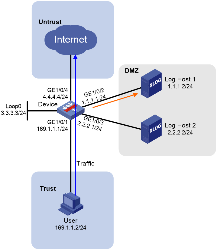
Network configuration
As shown in Figure 4, configure a flow log host group on the device to send flow log entries generated for the user only to Log Host 1.
Procedure
1. Assign IP addresses to interfaces.
# Assign an IP address to interface GigabitEthernet 1/0/1.
<Device> system-view
[Device] interface loopback 0
[Device-LoopBack0] ip address 3.3.3.3 255.255.255.0
[Device-LoopBack0] quit
[Device] interface gigabitethernet 1/0/1
[Device-GigabitEthernet 1/0/1] ip address 169.1.1.1 255.255.255.0
[Device-GigabitEthernet 1/0/1] quit
# Assign IP addresses to other interfaces in the same way. (Details not shown.)
2. Configure settings for routing.
This example configures a static route, and the next hop in the routes is 4.4.4.1.
[Device] ip route-static 0.0.0.0 0 4.4.4.1
3. Add interfaces to security zones.
[Device] security-zone name trust
[Device-security-zone-Trust] import interface gigabitethernet 1/0/1
[Device-security-zone-Trust] quit
[Device] security-zone name dmz
[Device-security-zone-DMZ] import interface gigabitethernet 1/0/2
[Device-security-zone-DMZ] import interface gigabitethernet 1/0/3
[Device-security-zone-DMZ] quit
[Device] security-zone name untrust
[Device-security-zone-Untrust] import interface gigabitethernet 1/0/4
[Device-security-zone-Untrust] quit
4. Configure a security policy.
# Configure a rule named loglocalout for the device to send log packets to the log hosts.
[Device] security-policy ip
[Device-security-policy-ip] rule name loglocalout
[Device-security-policy-ip-1-loglocalout] source-zone local
[Device-security-policy-ip-1-loglocalout] destination-zone dmz
[Device-security-policy-ip-1-loglocalout] source-ip-host 3.3.3.3
[Device-security-policy-ip-1-loglocalout] destination-ip-host 1.1.1.2
[Device-security-policy-ip-1-loglocalout] destination-ip-host 2.2.2.2
[Device-security-policy-ip-1-loglocalout] action pass
[Device-security-policy-ip-1-loglocalout] quit
[Device-security-policy-ip] quit
# Configure a rule named trust-untrust for the user to access the Internet.
[Device-security-policy-ip] rule name trust-untrust
[Device-security-policy-ip-3-trust-untrust] source-zone trust
[Device-security-policy-ip-3-trust-untrust] destination-zone untrust
[Device-security-policy-ip-3-trust-untrust] source-ip-subnet 169.1.1.0 24
[Device-security-policy-ip-3-trust-untrust] action pass
[Device-security-policy-ip-3-trust-untrust] quit
[Device-security-policy-ip] quit
5. Configure flow log settings.
# Enable NAT logging for session establishment events, session removal events, and active flows.
[Device] nat log enable
[Device] nat log flow-begin
[Device] nat log flow-end
[Device] nat log flow-active 10
# Specify the log hosts as the destinations for flow log export, set the UDP port number to 2000. Specify 3.3.3.3 as the source IP address for flow log packets.
[Device] userlog flow export host 1.1.1.2 port 2000
[Device] userlog flow export host 2.2.2.2 port 2000
[Device] userlog flow export source-ip 3.3.3.3
# Create ACL 2000 to match packets sent by the user.
[Device] acl basic 2000
[Device-acl-ipv4-basic-2000] rule permit source 169.1.1.2 0.0.0.0
[Device-acl-ipv4-basic-2000] quit
# Create an IPv4 flow log host group named test and specify ACL 2000 for it. Assign Log Host 1 to flow log host group test.
[Device] userlog host-group test acl number 2000
[Device-userlog-host-group-test] userlog host-group host flow 1.1.1.2
[Device-userlog-host-group-test] quit
Verifying the configuration
# Display information about flow log host group test.
[Device] display userlog host-group test
Userlog host-group test:
ACL number: 2000
Flow log host numbers: 1
Log host 1:
Host/port: 1.1.1.2/2000
# After the user comes online, display flow log export statistics.
[Device] display userlog export
Flow:
Export flow log as UDP Packet.
Version: 1.0
Source ipv4 address: 3.3.3.3
Log load balance function: Disabled
Local time stamp: Disabled
Number of log hosts: 2
Log host 1:
Host/Port: 1.1.1.2/2000
Total logs/UDP packets exported: 13/13
Log host 2:
Host/Port: 2.2.2.2/2000
Total logs/UDP packets exported: 0/0
Appendix A Flow message fields
This chapter describes message fields carried in flow packets from a device to a log host. The message formats vary by message parsing tool and might differ from your display.
Message header fields
Figure 5 Message header field description
|
Field |
Length (Bytes) |
Description |
|
Version |
1 |
Log version: · 1—Version 1.0. · 3—Version 3.0. · 5—Version 5.0. |
|
LogType |
1 |
Log type: · 4—NAT FLOW log. · 5—NAT66 FLOW log. · 7—AFT IPv6-to-IPv4 log. · 8—AFT IPv4-to-IPv6 log. · 11—LB IPv6-to-IPv4 NAT log. · 12—LB IPv4-to-IPv6 NAT log. · 13—LB IPv4-to-IPv4 NAT log. · 14—LB IPv6-to-IPv6 NAT log. |
|
Count |
2 |
Flow count in the range of 1 to 100. |
|
Second |
4 |
Time elapsed since 0 o'clock of 1970/1/1 till the packet generation, in seconds. |
|
FlowSequence |
4 |
Log packet sequence number or log packet count. All log packets are counted regardless of log type and log version. |
|
Chassis |
2 |
Number of the chassis that sent the log packet. |
|
Slot |
1 |
Number of the slot that sent the log packet. For centralized devices, this field is fixed at 0. For distributed devices, this field displays the actual slot number. |
|
Cpu |
1 |
Number of the CPU that sent the log packet. |
NAT flow message fields
The message fields vary by flow version. Use Table 1, Table 2, Table 3 and for Flow1.0, Flow3.0, and Flow5.0, respectively.
Table 1 NAT flow message fields for Flow1.0
|
Field |
Length (Bytes) |
Description |
|
SrcIP |
4 |
Source IP address before NAT translation. |
|
DestIP |
4 |
Destination IP address before NAT translation. |
|
SrcPort |
2 |
Source TCP/UDP port number before NAT translation. |
|
DestPort |
2 |
Destination TCP/UDP port number before NAT translation. |
|
StartTime |
4 |
Flow start time in seconds, time elapsed since 0 o'clock of 1970/1/1. |
|
EndTime |
4 |
Flow end time in seconds, time elapsed since 0 o'clock of 1970/1/1. This field is fixed at 0 if the Operator field is 6. |
|
Protocol |
1 |
Type of the protocol carried in the IP packet. |
|
Operator |
1 |
Operator ID that indicates the reason for log generation: · 0—Reserved. · 1—Flow end. · 2—Timer expiration. · 3—Flow aging out caused by configuration clearance of change. · 4—Flow aging out caused by insufficient resources. · 5—Reserved. · 6—Periodic recording of the connection status for active flows. · 7—Forced flow deletion on new flow creation. · 8—Flow creation. · FE—Others. · 10 to FE-1—Reserved for expansion. |
|
Reserved |
2 |
Reserved. |
Table 2 NAT flow message fields for Flow3.0
|
Field |
Length (Bytes) |
Description |
|
Protocol |
1 |
Type of the protocol carried in the IP packet. |
|
Operator |
1 |
Operator ID that indicates the reason for log generation: · 0—Reserved. · 1—Flow end. · 2—Timer expiration. · 3—Flow aging out caused by configuration clearance of change. · 4—Flow aging out caused by insufficient resources. · 5—Reserved. · 6—Periodic recording of the connection status for active flows. · 7—Forced flow deletion on new flow creation. · 8—Flow creation. · FE—Others. · 10 to FE-1—Reserved for expansion. |
|
IPVersion |
1 |
IP version. |
|
TosIPv4 |
1 |
IPv4 packet ToS. |
|
SourceIP |
4 |
Source IP address before NAT translation. |
|
SrcNatIP |
4 |
Source IP address after NAT translation. |
|
DestIP |
4 |
Destination IP address before NAT translation. |
|
DestNatIP |
4 |
Destination IP address after NAT translation. |
|
SrcPort |
2 |
Source TCP/UDP port number before NAT translation. |
|
SrcNatPort |
2 |
Source TCP/UDP port number after NAT translation. |
|
DestPort |
2 |
Destination TCP/UDP port number before NAT translation. |
|
DestNatPort |
2 |
Destination TCP/UDP port number after NAT translation. |
|
StartTime |
4 |
Flow start time in seconds, time elapsed since 0 o'clock of 1970/01/01. |
|
EndTime |
4 |
Flow end time in seconds, time elapsed since 0 o'clock of 1970/01/01. This field is fixed at 0 if the Operator field is 6. |
|
InTotalPkg |
4 |
Number of received packets. |
|
InTotalByte |
4 |
Bytes of received packets. |
|
OutTotalPkg |
4 |
Number of sent packets. |
|
OutTotalByte |
4 |
Bytes of sent packets. |
|
InVPNID |
1 |
Inbound VPN ID. |
|
OutVPNID |
1 |
Outbound VPN ID. |
|
Reserved1 |
2 |
Reserved. |
|
AppID |
4 |
Application protocol ID. |
|
Reserved3 |
4 |
Reserved. |
Table 3 NAT flow message fields for Flow5.0
|
Field |
Length (Bytes) |
Description |
|
Protocol |
1 |
Type of the protocol carried in the IP packet. |
|
Operator |
1 |
Operator ID that indicates the reason for log generation: · 0—Reserved. · 1—Flow end. · 2—Timer expiration. · 3—Flow aging out caused by configuration clearance of change. · 4—Flow aging out caused by insufficient resources. · 5—Reserved. · 6—Periodic recording of the connection status for active flows. · 7—Forced flow deletion on new flow creation. · 8—Flow creation. · FE—Others. · 10 to FE-1—Reserved for expansion. |
|
IPVersion |
1 |
IP version. |
|
TosIPv4 |
1 |
IPv4 packet ToS. |
|
SourceIP |
4 |
Source IP address before NAT translation. |
|
SrcNatIP |
4 |
Source IP address after NAT translation. |
|
DestIP |
4 |
Destination IP address before NAT translation. |
|
DestNatIP |
4 |
Destination IP address after NAT translation. |
|
SrcPort |
2 |
Source TCP/UDP port number before NAT translation. |
|
SrcNatPort |
2 |
Source TCP/UDP port number after NAT translation. |
|
DestPort |
2 |
Destination TCP/UDP port number before NAT translation. |
|
DestNatPort |
2 |
Destination TCP/UDP port number after NAT translation. |
|
StartTime |
4 |
Flow start time in seconds, time elapsed since 0 o'clock of 1970/01/01. |
|
EndTime |
4 |
Flow end time in seconds, time elapsed since 0 o'clock of 1970/01/01. This field is fixed at 0 if the Operator field is 6. |
|
InTotalPkg |
4 |
Number of received packets. |
|
InTotalByte |
4 |
Bytes of received packets. |
|
OutTotalPkg |
4 |
Number of sent packets. |
|
OutTotalByte |
4 |
Bytes of sent packets. |
|
InVPNID |
2 |
Inbound VPN ID. |
|
OutVPNID |
2 |
Outbound VPN ID. |
|
AppID |
4 |
Application protocol ID. |
|
UserName |
56 |
Username. |
|
Reserved1 |
4 |
Reserved. |
|
Reserved2 |
4 |
Reserved. |
|
Reserved3 |
4 |
Reserved. |
NAT66 flow message fields
The message fields vary by flow version. Use Table 4, Table 5, Table 6 and for Flow1.0, Flow3.0, and Flow5.0, respectively.
Table 4 NAT66 flow message fields for Flow1.0
|
Field |
Length (Bytes) |
Description |
|
SrcIP |
16 |
Source IPv6 address before NAT translation. |
|
DestIP |
16 |
Destination IPv6 address before NAT translation. |
|
SrcPort |
2 |
Source TCP/UDP port number before NAT translation. |
|
DestPort |
2 |
Destination TCP/UDP port number before NAT translation. |
|
StartTime |
4 |
Flow start time in seconds, time elapsed since 0 o'clock of 1970/01/01. |
|
EndTime |
4 |
Flow end time in seconds, time elapsed since 0 o'clock of 1970/01/01. This field is fixed at 0 if the Operator field is 6. |
|
Protocol |
1 |
Type of the protocol carried in the IP packet. |
|
Operator |
1 |
Operator ID that indicates the reason for log generation: · 0—Reserved. · 1—Flow end. · 2—Timer expiration. · 3—Flow aging out caused by configuration clearance of change. · 4—Flow aging out caused by insufficient resources. · 5—Reserved. · 6—Periodic recording of the connection status for active flows. · 7—Forced flow deletion on new flow creation. · 8—Flow creation. · FE—Others. · 10 to FE-1—Reserved for expansion. |
|
Reserved |
2 |
Reserved. |
Table 5 NAT66 flow message fields for Flow3.0
|
Field |
Length (Bytes) |
Description |
|
Protocol |
1 |
Type of the protocol carried in the IP packet. |
|
Operator |
1 |
Operator ID that indicates the reason for log generation: · 0—Reserved. · 1—Flow end. · 2—Timer expiration. · 3—Flow aging out caused by configuration clearance of change. · 4—Flow aging out caused by insufficient resources. · 5—Reserved. · 6—Periodic recording of the connection status for active flows. · 7—Forced flow deletion on new flow creation. · 8—Flow creation. · FE—Others. · 10 to FE-1—Reserved for expansion. |
|
IPVersion |
1 |
IP version. |
|
Traffic class |
1 |
IPv6 packet traffic class. |
|
SourceIP |
16 |
Source IPv6 packet before NAT translation. |
|
DestIP |
16 |
Destination IPv6 packet before NAT translation. |
|
SrcPort |
2 |
Source TCP/UDP port number before NAT translation. |
|
DestPort |
2 |
Destination TCP/UDP port number before NAT translation. |
|
StartTime |
4 |
Flow start time in seconds, time elapsed since 0 o'clock of 1970/01/01. |
|
EndTime |
4 |
Flow end time in seconds, time elapsed since 0 o'clock of 1970/01/01. This field is fixed at 0 if the Operator field is 6. |
|
InTotalPkg |
4 |
Number of received packets. |
|
InTotalByte |
4 |
Bytes of received packets. |
|
OutTotalPkg |
4 |
Number of sent packets. |
|
OutTotalByte |
4 |
Bytes of sent packets. |
|
InVPNID |
2 |
Inbound VPN ID. |
|
OutVPNID |
2 |
Outbound VPN ID. |
|
ContextID |
4 |
Session context ID. |
|
AppID |
4 |
Application protocol ID. |
Table 6 NAT66 flow message fields for Flow5.0
|
Field |
Length (Bytes) |
Description |
|
Protocol |
1 |
Type of the protocol carried in the IP packet. |
|
Operator |
1 |
Operator ID that indicates the reason for log generation: · 0—Reserved. · 1—Flow end. · 2—Timer expiration. · 3—Flow aging out caused by configuration clearance of change. · 4—Flow aging out caused by insufficient resources. · 5—Reserved. · 6—Periodic recording of the connection status for active flows. · 7—Forced flow deletion on new flow creation. · 8—Flow creation. · FE—Others. · 10 to FE-1—Reserved for expansion. |
|
IPVersion |
1 |
IP version. |
|
Traffic class |
1 |
IPv6 packet traffic class. |
|
SourceIP |
16 |
Source IPv6 address before NAT translation. |
|
DestIP |
16 |
Destination IPv6 address before NAT translation. |
|
SrcPort |
2 |
Source TCP/UDP port number before NAT translation. |
|
DestPort |
2 |
Destination TCP/UDP port number before NAT translation. |
|
StartTime |
4 |
Flow start time in seconds, time elapsed since 0 o'clock of 1970/01/01. |
|
EndTime |
4 |
Flow end time in seconds, time elapsed since 0 o'clock of 1970/01/01. This field is fixed at 0 if the Operator field is 6. |
|
InTotalPkg |
4 |
Number of received packets. |
|
InTotalByte |
4 |
Bytes of received packets. |
|
OutTotalPkg |
4 |
Number of sent packets. |
|
OutTotalByte |
4 |
Bytes of sent packets. |
|
InVPNID |
2 |
Inbound VPN ID. |
|
OutVPNID |
2 |
Outbound VPN ID. |
|
ContextID |
4 |
Session context ID. |
|
AppID |
4 |
Application protocol ID. |
|
UserName |
56 |
Username. |
|
Reserved1 |
4 |
Reserved. |
|
Reserved2 |
4 |
Reserved. |
|
Reserved3 |
4 |
Reserved. |
AFT IPv6-to-IPv4 flow message fields
The message fields vary by flow version. Use Table 7, Table 8, Table 9 and for Flow1.0, Flow3.0, and Flow5.0, respectively.
Table 7 AFT IPv6-to-IPv4 flow message fields for Flow1.0
|
Field |
Length (Bytes) |
Description |
|
Protocol |
1 |
Type of the protocol carried in the IP packet. |
|
Operator |
1 |
Operator ID that indicates the reason for log generation: · 0—Reserved. · 1—Flow end. · 2—Timer expiration. · 3—Flow aging out caused by configuration clearance of change. · 4—Flow aging out caused by insufficient resources. · 5—Reserved. · 6—Periodic recording of the connection status for active flows. · 7—Forced flow deletion on new flow creation. · 8—Flow creation. · FE—Others. · 10 to FE-1—Reserved for expansion. |
|
IPVersion |
1 |
IP version. |
|
Traffic class |
1 |
IPv6 packet traffic class. |
|
SourceIP |
16 |
Source IPv6 address before NAT translation. |
|
SrcNatIP |
4 |
Source IPv4 address after NAT translation. |
|
DestIP |
16 |
Destination IPv6 address before NAT translation. |
|
DestNatIP |
4 |
Destination IPv4 address after NAT translation. |
|
SrcPort |
2 |
Source TCP/UDP port number before NAT translation. |
|
SrcNatPort |
2 |
Source TCP/UDP port number after NAT translation. |
|
DestPort |
2 |
Destination TCP/UDP port number before NAT translation. |
|
DestNatPort |
2 |
Destination TCP/UDP port number after NAT translation. |
|
StartTime |
4 |
Flow start time in seconds, time elapsed since 0 o'clock of 1970/01/01. |
|
EndTime |
4 |
Flow end time in seconds, time elapsed since 0 o'clock of 1970/01/01. This field is fixed at 0 if the Operator field is 6. |
|
InTotalPkg |
4 |
Number of received packets. |
|
InTotalByte |
4 |
Bytes of received packets. |
|
OutTotalPkg |
4 |
Number of sent packets. |
|
OutTotalByte |
4 |
Bytes of sent packets. |
|
InVPNID |
2 |
Inbound VPN ID. |
|
OutVPNID |
2 |
Outbound VPN ID. |
|
ContextID |
4 |
Session context ID. |
|
Reserved |
4 |
Reserved. |
Table 8 AFT IPv6-to-IPv4 flow message fields for Flow3.0
|
Field |
Length (Bytes) |
Description |
|
Protocol |
1 |
Type of the protocol carried in the IP packet. |
|
Operator |
1 |
Operator ID that indicates the reason for log generation: · 0—Reserved. · 1—Flow end. · 2—Timer expiration. · 3—Flow aging out caused by configuration clearance of change. · 4—Flow aging out caused by insufficient resources. · 5—Reserved. · 6—Periodic recording of the connection status for active flows. · 7—Forced flow deletion on new flow creation. · 8—Flow creation. · FE—Others. · 10 to FE-1—Reserved for expansion. |
|
IPVersion |
1 |
IP version. |
|
Traffic class |
1 |
IPv6 packet traffic class. |
|
SourceIP |
16 |
Source IPv6 address before NAT translation. |
|
SrcNatIP |
4 |
Source IPv4 address after NAT translation. |
|
DestIP |
16 |
Destination IPv6 address before NAT translation. |
|
DestNatIP |
4 |
Destination IPv4 address after NAT translation. |
|
SrcPort |
2 |
Source TCP/UDP port number before NAT translation. |
|
SrcNatPort |
2 |
Source TCP/UDP port number after NAT translation. |
|
DestPort |
2 |
Destination TCP/UDP port number before NAT translation. |
|
DestNatPort |
2 |
Destination TCP/UDP port number after NAT translation. |
|
StartTime |
4 |
Flow start time in seconds, time elapsed since 0 o'clock of 1970/01/01. |
|
EndTime |
4 |
Flow end time in seconds, time elapsed since 0 o'clock of 1970/01/01. This field is fixed at 0 if the Operator field is 6. |
|
InTotalPkg |
4 |
Number of received packets. |
|
InTotalByte |
4 |
Bytes of received packets. |
|
OutTotalPkg |
4 |
Number of sent packets. |
|
OutTotalByte |
4 |
Bytes of sent packets. |
|
InVPNID |
2 |
Inbound VPN ID. |
|
OutVPNID |
2 |
Outbound VPN ID. |
|
ContextID |
4 |
Session context ID. |
|
Reserved |
4 |
Reserved. |
Table 9 AFT IPv6-to-IPv4 flow message fields for Flow5.0
|
Field |
Length (Bytes) |
Description |
|
Protocol |
1 |
Type of the protocol carried in the IP packet. |
|
Operator |
1 |
Operator ID that indicates the reason for log generation: · 0—Reserved. · 1—Flow end. · 2—Timer expiration. · 3—Flow aging out caused by configuration clearance of change. · 4—Flow aging out caused by insufficient resources. · 5—Reserved. · 6—Periodic recording of the connection status for active flows. · 7—Forced flow deletion on new flow creation. · 8—Flow creation. · FE—Others. · 10 to FE-1—Reserved for expansion. |
|
IPVersion |
1 |
IP version. |
|
Traffic class |
1 |
IPv6 packet traffic class. |
|
SourceIP |
16 |
Source IPv6 address before NAT translation. |
|
SrcNatIP |
4 |
Source IPv4 address after NAT translation. |
|
DestIP |
16 |
Destination IPv6 address before NAT translation. |
|
DestNatIP |
4 |
Destination IPv4 address after NAT translation. |
|
SrcPort |
2 |
Source TCP/UDP port number before NAT translation. |
|
SrcNatPort |
2 |
Source TCP/UDP port number after NAT translation. |
|
DestPort |
2 |
Destination TCP/UDP port number before NAT translation. |
|
DestNatPort |
2 |
Destination TCP/UDP port number after NAT translation. |
|
StartTime |
4 |
Flow start time in seconds, time elapsed since 0 o'clock of 1970/01/01. |
|
EndTime |
4 |
Flow end time in seconds, time elapsed since 0 o'clock of 1970/01/01. This field is fixed at 0 if the Operator field is 6. |
|
InTotalPkg |
4 |
Number of received packets. |
|
InTotalByte |
4 |
Bytes of received packets. |
|
OutTotalPkg |
4 |
Number of sent packets. |
|
OutTotalByte |
4 |
Bytes of sent packets. |
|
InVPNID |
2 |
Inbound VPN ID. |
|
OutVPNID |
2 |
Outbound VPN ID. |
|
ContextID |
4 |
Session context ID. |
|
UserName |
56 |
Username. |
|
Reserved1 |
4 |
Reserved. |
|
Reserved2 |
4 |
Reserved. |
|
Reserved3 |
4 |
Reserved. |
AFT IPv4-to-IPv6 flow message fields
The message fields vary by flow version. Use Table 10, Table 11, Table 12 and for Flow1.0, Flow3.0, and Flow5.0, respectively.
Table 10 AFT IPv4-to-IPv6 flow message fields for Flow1.0
|
Field |
Length (Bytes) |
Description |
|
Protocol |
1 |
Type of the protocol carried in the IP packet. |
|
Operator |
1 |
Operator ID that indicates the reason for log generation: · 0—Reserved. · 1—Flow end. · 2—Timer expiration. · 3—Flow aging out caused by configuration clearance of change. · 4—Flow aging out caused by insufficient resources. · 5—Reserved. · 6—Periodic recording of the connection status for active flows. · 7—Forced flow deletion on new flow creation. · 8—Flow creation. · FE—Others. · 10 to FE-1—Reserved for expansion. |
|
IPVersion |
1 |
IP version. |
|
TosIPv4 |
1 |
IPv4 packet ToS. |
|
SourceIP |
4 |
Source IPv4 address before NAT translation. |
|
SrcNatIP |
16 |
Source IPv6 address after NAT translation. |
|
DestIP |
4 |
Destination IPv4 address before NAT translation. |
|
DestNatIP |
16 |
Destination IPv6 address after NAT translation. |
|
SrcPort |
2 |
Source TCP/UDP port number before NAT translation. |
|
SrcNatPort |
2 |
Source TCP/UDP port number after NAT translation. |
|
DestPort |
2 |
Destination TCP/UDP port number before NAT translation. |
|
DestNatPort |
2 |
Destination TCP/UDP port number after NAT translation. |
|
StartTime |
4 |
Flow start time in seconds, time elapsed since 0 o'clock of 1970/01/01. |
|
EndTime |
4 |
Flow end time in seconds, time elapsed since 0 o'clock of 1970/01/01. This field is fixed at 0 if the Operator field is 6. |
|
InTotalPkg |
4 |
Number of received packets. |
|
InTotalByte |
4 |
Bytes of received packets. |
|
OutTotalPkg |
4 |
Number of sent packets. |
|
OutTotalByte |
4 |
Bytes of sent packets. |
|
InVPNID |
2 |
Inbound VPN ID. |
|
OutVPNID |
2 |
Outbound VPN ID. |
|
ContextID |
4 |
Session context ID. |
|
Reserved |
4 |
Reserved. |
Table 11 AFT IPv4-to-IPv6 flow message fields for Flow3.0
|
Field |
Length (Bytes) |
Description |
|
Protocol |
1 |
Type of the protocol carried in the IP packet. |
|
Operator |
1 |
Operator ID that indicates the reason for log generation: · 0—Reserved. · 1—Flow end. · 2—Timer expiration. · 3—Flow aging out caused by configuration clearance of change. · 4—Flow aging out caused by insufficient resources. · 5—Reserved. · 6—Periodic recording of the connection status for active flows. · 7—Forced flow deletion on new flow creation. · 8—Flow creation. · FE—Others. · 10 to FE-1—Reserved for expansion. |
|
IPVersion |
1 |
IP version. |
|
TosIPv4 |
1 |
IPv4 packet ToS. |
|
SourceIP |
4 |
Source IPv4 address before NAT translation. |
|
SrcNatIP |
16 |
Source IPv6 address after NAT translation. |
|
DestIP |
4 |
Destination IPv4 address before NAT translation. |
|
DestNatIP |
16 |
Destination IPv6 address after NAT translation. |
|
SrcPort |
2 |
Source TCP/UDP port number before NAT translation. |
|
SrcNatPort |
2 |
Source TCP/UDP port number after NAT translation. |
|
DestPort |
2 |
Destination TCP/UDP port number before NAT translation. |
|
DestNatPort |
2 |
Destination TCP/UDP port number after NAT translation. |
|
StartTime |
4 |
Flow start time in seconds, time elapsed since 0 o'clock of 1970/01/01. |
|
EndTime |
4 |
Flow end time in seconds, time elapsed since 0 o'clock of 1970/01/01. This field is fixed at 0 if the Operator field is 6. |
|
InTotalPkg |
4 |
Number of received packets. |
|
InTotalByte |
4 |
Bytes of received packets. |
|
OutTotalPkg |
4 |
Number of sent packets. |
|
OutTotalByte |
4 |
Bytes of sent packets. |
|
InVPNID |
2 |
Inbound VPN ID. |
|
OutVPNID |
2 |
Outbound VPN ID. |
|
ContextID |
4 |
Session context ID. |
|
Reserved |
4 |
Reserved. |
Table 12 AFT IPv4-to-IPv6 flow message fields for Flow5.0
|
Field |
Length (Bytes) |
Description |
|
Protocol |
1 |
Type of the protocol carried in the IP packet. |
|
Operator |
1 |
Operator ID that indicates the reason for log generation: · 0—Reserved. · 1—Flow end. · 2—Timer expiration. · 3—Flow aging out caused by configuration clearance of change. · 4—Flow aging out caused by insufficient resources. · 5—Reserved. · 6—Periodic recording of the connection status for active flows. · 7—Forced flow deletion on new flow creation. · 8—Flow creation. · FE—Others. · 10 to FE-1—Reserved for expansion. |
|
IPVersion |
1 |
IP version. |
|
TosIPv4 |
1 |
IPv4 packet ToS. |
|
SourceIP |
4 |
Source IPv4 address before NAT translation. |
|
SrcNatIP |
16 |
Source IPv6 address after NAT translation. |
|
DestIP |
4 |
Destination IPv4 address before NAT translation. |
|
DestNatIP |
16 |
Destination IPv6 address after NAT translation. |
|
SrcPort |
2 |
Source TCP/UDP port number before NAT translation. |
|
SrcNatPort |
2 |
Source TCP/UDP port number after NAT translation. |
|
DestPort |
2 |
Destination TCP/UDP port number before NAT translation. |
|
DestNatPort |
2 |
Destination TCP/UDP port number after NAT translation. |
|
StartTime |
4 |
Flow start time in seconds, time elapsed since 0 o'clock of 1970/01/01. |
|
EndTime |
4 |
Flow end time in seconds, time elapsed since 0 o'clock of 1970/01/01. This field is fixed at 0 if the Operator field is 6. |
|
InTotalPkg |
4 |
Number of received packets. |
|
InTotalByte |
4 |
Bytes of received packets. |
|
OutTotalPkg |
4 |
Number of sent packets. |
|
OutTotalByte |
4 |
Bytes of sent packets. |
|
InVPNID |
2 |
Inbound VPN ID. |
|
OutVPNID |
2 |
Outbound VPN ID. |
|
ContextID |
4 |
Session context ID. |
|
UserName |
56 |
Username. |
|
Reserved1 |
4 |
Reserved. |
|
Reserved2 |
4 |
Reserved. |
|
Reserved3 |
4 |
Reserved. |
LB NAT64 flow message fields
The message fields vary by flow version. Use Table 13, Table 14, Table 15 and for Flow1.0, Flow3.0, and Flow5.0, respectively.
Table 13 LB NAT64 flow message fields for Flow1.0
|
Field |
Length (Bytes) |
Description |
|
LBVersion |
1 |
LB log version. |
|
Protocol |
1 |
Type of the protocol carried in the IP packet. |
|
IPVersion |
1 |
IP version. |
|
Reserved1 |
1 |
Reserved. |
|
SrcIP |
16 |
Source IP address before NAT translation. |
|
SrcNatIP |
4 |
Source IP address after NAT translation. |
|
DestIP |
16 |
Destination IP address before NAT translation. |
|
DestNatIP |
4 |
Destination IP address after NAT translation. |
|
SrcPort |
2 |
Source TCP/UDP port number before NAT translation. |
|
SrcNatPort |
2 |
Source TCP/UDP port number after NAT translation. |
|
DestPort |
2 |
Destination TCP/UDP port number before NAT translation. |
|
DestNatPort |
2 |
Destination TCP/UDP port number after NAT translation. |
|
InVPNID |
2 |
Inbound VPN ID. |
|
OutVPNID |
2 |
Outbound VPN ID. |
|
ContextID |
4 |
Context ID. |
|
Reserved2 |
4 |
Reserved. |
Table 14 LB NAT64 flow message fields for Flow3.0
|
Field |
Length (Bytes) |
Description |
|
LBVersion |
1 |
LB log version. |
|
Protocol |
1 |
Type of the protocol carried in the IP packet. |
|
IPVersion |
1 |
IP version. |
|
Reserved1 |
1 |
Reserved. |
|
SrcIP |
16 |
Source IP address before NAT translation. |
|
SrcNatIP |
4 |
Source IP address after NAT translation. |
|
DestIP |
16 |
Destination IP address before NAT translation. |
|
DestNatIP |
4 |
Destination IP address after NAT translation. |
|
SrcPort |
2 |
Source TCP/UDP port number before NAT translation. |
|
SrcNatPort |
2 |
Source TCP/UDP port number after NAT translation. |
|
DestPort |
2 |
Destination TCP/UDP port number before NAT translation. |
|
DestNatPort |
2 |
Destination TCP/UDP port number after NAT translation. |
|
InVPNID |
2 |
Inbound VPN ID. |
|
OutVPNID |
2 |
Outbound VPN ID. |
|
ContextID |
4 |
Context ID |
|
Reserved2 |
4 |
Reserved. |
Table 15 LB NAT64 flow message fields for Flow5.0
|
Field |
Length (Bytes) |
Description |
|
LBVersion |
1 |
LB log version. |
|
Protocol |
1 |
Type of the protocol carried in the IP packet. |
|
IPVersion |
1 |
IP version. |
|
Reserved1 |
1 |
Reserved. |
|
SrcIP |
16 |
Source IP address before NAT translation. |
|
SrcNatIP |
4 |
Source IP address after NAT translation. |
|
DestIP |
16 |
Destination IP address before NAT translation. |
|
DestNatIP |
4 |
Destination IP address after NAT translation. |
|
SrcPort |
2 |
Source TCP/UDP port number before NAT translation. |
|
SrcNatPort |
2 |
Source TCP/UDP port number after NAT translation. |
|
DestPort |
2 |
Destination TCP/UDP port number before NAT translation. |
|
DestNatPort |
2 |
Destination TCP/UDP port number after NAT translation. |
|
InVPNID |
2 |
Inbound VPN ID. |
|
OutVPNID |
2 |
Outbound VPN ID. |
|
ContextID |
4 |
Context ID |
|
UserName |
56 |
Username. |
|
Reserved1 |
4 |
Reserved. |
|
Reserved2 |
4 |
Reserved. |
|
Reserved3 |
4 |
Reserved. |
LB NAT46 flow message fields
The message fields vary by flow version. Use Table 16, Table 17, Table 18 and for Flow1.0, Flow3.0, and Flow5.0, respectively.
Table 16 LB NAT46 flow message fields for Flow1.0
|
Field |
Length (Bytes) |
Description |
|
LBVersion |
1 |
LB log version. |
|
Protocol |
1 |
Type of the protocol carried in the IP packet. |
|
IPVersion |
1 |
IP version. |
|
Reserved1 |
1 |
Reserved. |
|
SrcIP |
4 |
Source IP address before NAT translation. |
|
SrcNatIP |
16 |
Source IP address after NAT translation. |
|
DestIP |
4 |
Destination IP address before NAT translation. |
|
DestNatIP |
16 |
Destination IP address after NAT translation. |
|
SrcPort |
2 |
Source TCP/UDP port number before NAT translation. |
|
SrcNatPort |
2 |
Source TCP/UDP port number after NAT translation. |
|
DestPort |
2 |
Destination TCP/UDP port number before NAT translation. |
|
DestNatPort |
2 |
Destination TCP/UDP port number after NAT translation. |
|
InVPNID |
2 |
Inbound VPN ID. |
|
OutVPNID |
2 |
Outbound VPN ID. |
|
ContextID |
4 |
Context ID |
|
Reserved2 |
4 |
Reserved. |
Table 17 LB NAT46 flow message fields for Flow3.0
|
Field |
Length (Bytes) |
Description |
|
LBVersion |
1 |
LB log version. |
|
Protocol |
1 |
Type of the protocol carried in the IP packet. |
|
IPVersion |
1 |
IP version. |
|
Reserved1 |
1 |
Reserved. |
|
SrcIP |
4 |
Source IP address before NAT translation. |
|
SrcNatIP |
16 |
Source IP address after NAT translation. |
|
DestIP |
4 |
Destination IP address before NAT translation. |
|
DestNatIP |
16 |
Destination IP address after NAT translation. |
|
SrcPort |
2 |
Source TCP/UDP port number before NAT translation. |
|
SrcNatPort |
2 |
Source TCP/UDP port number after NAT translation. |
|
DestPort |
2 |
Destination TCP/UDP port number before NAT translation. |
|
DestNatPort |
2 |
Destination TCP/UDP port number after NAT translation. |
|
InVPNID |
2 |
Inbound VPN ID. |
|
OutVPNID |
2 |
Outbound VPN ID. |
|
ContextID |
4 |
Context ID |
|
Reserved2 |
4 |
Reserved. |
Table 18 LB NAT46 flow message fields for Flow5.0
|
Field |
Length (Bytes) |
Description |
|
LBVersion |
1 |
LB log version. |
|
Protocol |
1 |
Type of the protocol carried in the IP packet. |
|
IPVersion |
1 |
IP version. |
|
Reserved1 |
1 |
Reserved. |
|
SrcIP |
4 |
Source IP address before NAT translation. |
|
SrcNatIP |
16 |
Source IP address after NAT translation. |
|
DestIP |
4 |
Destination IP address before NAT translation. |
|
DestNatIP |
16 |
Destination IP address after NAT translation. |
|
SrcPort |
2 |
Source TCP/UDP port number before NAT translation. |
|
SrcNatPort |
2 |
Source TCP/UDP port number after NAT translation. |
|
DestPort |
2 |
Destination TCP/UDP port number before NAT translation. |
|
DestNatPort |
2 |
Destination TCP/UDP port number after NAT translation. |
|
InVPNID |
2 |
Inbound VPN ID. |
|
OutVPNID |
2 |
Outbound VPN ID. |
|
ContextID |
4 |
Context ID |
|
UserName |
56 |
Username. |
|
Reserved1 |
4 |
Reserved. |
|
Reserved2 |
4 |
Reserved. |
|
Reserved3 |
4 |
Reserved. |
LB NAT44 flow message fields
The message fields vary by flow version. Use Table 19, Table 20, Table 21 and for Flow1.0, Flow3.0, and Flow5.0, respectively.
Table 19 LB NAT44 flow message fields for Flow1.0
|
Field |
Length (Bytes) |
Description |
|
LBVersion |
1 |
LB log version. |
|
Protocol |
1 |
Type of the protocol carried in the IP packet. |
|
IPVersion |
1 |
IP version. |
|
Reserved1 |
1 |
Reserved. |
|
SrcIP |
4 |
Source IP address before NAT translation. |
|
SrcNatIP |
4 |
Source IP address after NAT translation. |
|
DestIP |
4 |
Destination IP address before NAT translation. |
|
DestNatIP |
4 |
Destination IP address after NAT translation. |
|
SrcPort |
2 |
Source TCP/UDP port number before NAT translation. |
|
SrcNatPort |
2 |
Source TCP/UDP port number after NAT translation. |
|
DestPort |
2 |
Destination TCP/UDP port number before NAT translation. |
|
DestNatPort |
2 |
Destination TCP/UDP port number after NAT translation. |
|
InVPNID |
2 |
Inbound VPN ID. |
|
OutVPNID |
2 |
Outbound VPN ID. |
|
ContextID |
4 |
Context ID. |
|
Reserved2 |
4 |
Reserved. |
Table 20 LB NAT44 flow message fields for Flow3.0
|
Field |
Length (Bytes) |
Description |
|
LBVersion |
1 |
LB log version. |
|
Protocol |
1 |
Type of the protocol carried in the IP packet. |
|
IPVersion |
1 |
IP version. |
|
Reserved1 |
1 |
Reserved. |
|
SrcIP |
4 |
Source IP address before NAT translation. |
|
SrcNatIP |
4 |
Source IP address after NAT translation. |
|
DestIP |
4 |
Destination IP address before NAT translation. |
|
DestNatIP |
4 |
Destination IP address after NAT translation. |
|
SrcPort |
2 |
Source TCP/UDP port number before NAT translation. |
|
SrcNatPort |
2 |
Source TCP/UDP port number after NAT translation. |
|
DestPort |
2 |
Destination TCP/UDP port number before NAT translation. |
|
DestNatPort |
2 |
Destination TCP/UDP port number after NAT translation. |
|
InVPNID |
2 |
Inbound VPN ID. |
|
OutVPNID |
2 |
Outbound VPN ID. |
|
ContextID |
4 |
Context ID. |
|
Reserved2 |
4 |
Reserved. |
Table 21 LB NAT44 flow message fields for Flow5.0
|
Field |
Length (Bytes) |
Description |
|
LBVersion |
1 |
LB log version. |
|
Protocol |
1 |
Type of the protocol carried in the IP packet. |
|
IPVersion |
1 |
IP version. |
|
Reserved1 |
1 |
Reserved. |
|
SrcIP |
4 |
Source IP address before NAT translation. |
|
SrcNatIP |
4 |
Source IP address after NAT translation. |
|
DestIP |
4 |
Destination IP address before NAT translation. |
|
DestNatIP |
4 |
Destination IP address after NAT translation. |
|
SrcPort |
2 |
Source TCP/UDP port number before NAT translation. |
|
SrcNatPort |
2 |
Source TCP/UDP port number after NAT translation. |
|
DestPort |
2 |
Destination TCP/UDP port number before NAT translation. |
|
DestNatPort |
2 |
Destination TCP/UDP port number after NAT translation. |
|
InVPNID |
2 |
Inbound VPN ID. |
|
OutVPNID |
2 |
Outbound VPN ID. |
|
ContextID |
4 |
Context ID. |
|
UserName |
56 |
Username. |
|
Reserved1 |
4 |
Reserved. |
|
Reserved2 |
4 |
Reserved. |
|
Reserved3 |
4 |
Reserved. |
LB NAT66 flow message fields
The message fields vary by flow version. Use Table 22, Table 23, Table 24 and for Flow1.0, Flow3.0, and Flow5.0, respectively.
Table 22 LB NAT66 flow message fields for Flow1.0
|
Field |
Length (Bytes) |
Description |
|
LBVersion |
1 |
LB log version. |
|
Protocol |
1 |
Type of the protocol carried in the IP packet. |
|
IPVersion |
1 |
IP version. |
|
Reserved1 |
1 |
Reserved. |
|
SrcIP |
16 |
Source IP address before NAT translation. |
|
SrcNatIP |
16 |
Source IP address after NAT translation. |
|
DestIP |
16 |
Destination IP address before NAT translation. |
|
DestNatIP |
16 |
Destination IP address after NAT translation. |
|
SrcPort |
2 |
Source TCP/UDP port number before NAT translation. |
|
SrcNatPort |
2 |
Source TCP/UDP port number after NAT translation. |
|
DestPort |
2 |
Destination TCP/UDP port number before NAT translation. |
|
DestNatPort |
2 |
Destination TCP/UDP port number after NAT translation. |
|
InVPNID |
2 |
Inbound VPN ID. |
|
OutVPNID |
2 |
Outbound VPN ID. |
|
ContextID |
4 |
Context ID. |
|
Reserved2 |
4 |
Reserved. |
Table 23 LB NAT66 flow message fields for Flow3.0
|
Field |
Length (Bytes) |
Description |
|
LBVersion |
1 |
LB log version. |
|
Protocol |
1 |
Type of the protocol carried in the IP packet. |
|
IPVersion |
1 |
IP version. |
|
Reserved1 |
1 |
Reserved. |
|
SrcIP |
16 |
Source IP address before NAT translation. |
|
SrcNatIP |
16 |
Source IP address after NAT translation. |
|
DestIP |
16 |
Destination IP address before NAT translation. |
|
DestNatIP |
16 |
Destination IP address after NAT translation. |
|
SrcPort |
2 |
Source TCP/UDP port number before NAT translation. |
|
SrcNatPort |
2 |
Source TCP/UDP port number after NAT translation. |
|
DestPort |
2 |
Destination TCP/UDP port number before NAT translation. |
|
DestNatPort |
2 |
Destination TCP/UDP port number after NAT translation. |
|
InVPNID |
2 |
Inbound VPN ID. |
|
OutVPNID |
2 |
Outbound VPN ID. |
|
ContextID |
4 |
Context ID. |
|
Reserved2 |
4 |
Reserved. |
Table 24 LB NAT66 flow message fields for Flow5.0
|
Field |
Length (Bytes) |
Description |
|
LBVersion |
1 |
LB log version. |
|
Protocol |
1 |
Type of the protocol carried in the IP packet. |
|
IPVersion |
1 |
IP version. |
|
Reserved1 |
1 |
Reserved. |
|
SrcIP |
16 |
Source IP address before NAT translation. |
|
SrcNatIP |
16 |
Source IP address after NAT translation. |
|
DestIP |
16 |
Destination IP address before NAT translation. |
|
DestNatIP |
16 |
Destination IP address after NAT translation. |
|
SrcPort |
2 |
Source TCP/UDP port number before NAT translation. |
|
SrcNatPort |
2 |
Source TCP/UDP port number after NAT translation. |
|
DestPort |
2 |
Destination TCP/UDP port number before NAT translation. |
|
DestNatPort |
2 |
Destination TCP/UDP port number after NAT translation. |
|
InVPNID |
2 |
Inbound VPN ID. |
|
OutVPNID |
2 |
Outbound VPN ID. |
|
ContextID |
4 |
Context ID. |
|
UserName |
56 |
Username. |
|
Reserved1 |
4 |
Reserved. |
|
Reserved2 |
4 |
Reserved. |
|
Reserved3 |
4 |
Reserved. |