- Table of Contents
-
- 10-MPLS Configuration Guide
- 00-Preface
- 01-Basic MPLS configuration
- 02-Static LSP configuration
- 03-LDP configuration
- 04-MPLS TE configuration
- 05-Static CRLSP configuration
- 06-RSVP configuration
- 07-Tunnel policy configuration
- 08-MPLS L3VPN configuration
- 09-MPLS L2VPN configuration
- 10-VPLS configuration
- 11-L2VPN access to L3VPN or IP backbone configuration
- 12-MPLS OAM configuration
- 13-MPLS protection switching configuration
- 14-MCE configuration
- Related Documents
-
| Title | Size | Download |
|---|---|---|
| 04-MPLS TE configuration | 874.46 KB |
Contents
CRLSP establishment using PCE path calculation
Restrictions: Hardware compatibility with MPLS TE
Establishing a CRLSP dynamically
Establishing a CRLSP by using the path calculated by PCEs
Configuring a tunnel interface
Configuring an MPLS TE tunnel to use a static CRLSP
Configuring MPLS TE attributes for a link
Advertising link TE attributes by using IGP TE extension
Restrictions and guidelines for advertising link TE attributes by using IGP TE extension
Configuring MPLS TE tunnel constraints
Configuring bandwidth constraints for an MPLS TE tunnel
Configuring the affinity attribute for an MPLS TE tunnel
Setting a setup priority and a holding priority for an MPLS TE tunnel
Configuring an explicit path for an MPLS TE tunnel
Establishing an MPLS TE tunnel by using RSVP-TE
Controlling CRLSP path selection
Restrictions and guidelines for CRLSP path selection control
Configuring the metric type for path selection
Configuring tunnel reoptimization
Setting TE flooding thresholds and interval
Controlling MPLS TE tunnel setup
About MPLS TE tunnel setup control
Restrictions and guidelines for MPLS TE tunnel setup control
Enabling route and label recording
Configuring RSVP resource reservation style
Configuring an MPLS TE tunnel to use a CRLSP calculated by PCEs
Establishing a CRLSP by using the path calculated by PCEs
Configuring stateful PCE on a PCC
Configuring PCEP session parameters
Configuring unequal load sharing for an MPLS TE tunnel
Configuring static routing to direct traffic to an MPLS TE tunnel or tunnel bundle
Configuring PBR to direct traffic to an MPLS TE tunnel
Configuring automatic route advertisement to direct traffic to an MPLS TE tunnel
Configuring a bidirectional MPLS TE tunnel
Configuring CRLSP backup for MPLS TE tunnels established through RSVP-TE
Configuring a backup CRLSP by using the path calculated by PCEs
Restrictions and guidelines for MPLS TE FRR
Configuring a bypass tunnel on the PLR
Configuring node fault detection
Setting the optimal bypass tunnel selection interval
Enabling SNMP notifications for MPLS TE
Display and maintenance commands for MPLS TE
MPLS TE configuration examples
Example: Establishing an MPLS TE tunnel over a static CRLSP
Example: Establishing an MPLS TE tunnel with RSVP-TE
Example: Establishing an inter-AS MPLS TE tunnel with RSVP-TE
Example: Establishing an inter-area MPLS TE tunnel over a CRLSP calculated by PCEs
Example: Configuring bidirectional MPLS TE tunnel
Example: Configuring CRLSP backup
Example: Configuring manual bypass tunnel for FRR
Example: Configuring IETF DS-TE
Configuring MPLS TE
About MPLS TE
TE and MPLS TE
Network congestion can degrade the network backbone performance. It might occur when network resources are inadequate or when load distribution is unbalanced. Traffic engineering (TE) is intended to avoid the latter situation where partial congestion might occur because of improper resource allocation.
TE can make the best use of network resources and avoid uneven load distribution by using the following functionalities:
· Real-time monitoring of traffic and traffic load on network elements.
· Dynamic tuning of traffic management attributes, routing parameters, and resources constraints.
MPLS TE combines the MPLS technology and traffic engineering. It reserves resources by establishing LSP tunnels along the specified paths, allowing traffic to bypass congested nodes to achieve appropriate load distribution.
With MPLS TE, a service provider can deploy traffic engineering on the existing MPLS backbone to provide various services and optimize network resources management.
MPLS TE basic concepts
CRLSP
To establish a Constraint-based Routed Label Switched Path (CRLSP), you must configure routing, and specify constraints, such as the bandwidth and explicit paths.
MPLS TE tunnel
An MPLS TE tunnel is a virtual point-to-point connection from the ingress node to the egress node. Typically, an MPLS TE tunnel consists of one CRLSP. To deploy CRLSP backup or transmit traffic over multiple paths, you need to establish multiple CRLSPs for one class of traffic. In this case, an MPLS TE tunnel consists of a set of CRLSPs. An MPLS TE tunnel is identified by an MPLS TE tunnel interface on the ingress node. When the outgoing interface of a traffic flow is an MPLS TE tunnel interface, the traffic flow is forwarded through the CRLSP of the MPLS TE tunnel.
Static CRLSP establishment
A static CRLSP is established by manually specifying the incoming label, outgoing label, and other constraints on each hop along the path that the traffic travels. Static CRLSPs feature simple configuration, but they cannot automatically adapt to network changes.
For more information about static CRLSPs, see "Configuring a static CRLSP."
Dynamic CRLSP establishment
Dynamic CRLSPs are dynamically established as follows:
1. An IGP advertises TE attributes for links.
2. MPLS TE uses the CSPF algorithm to calculate the shortest path to the tunnel destination.
The path must meet constraints such as bandwidth and explicit routing.
3. A label distribution protocol (such as RSVP-TE) advertises labels to establish CRLSPs and reserves bandwidth resources on each node along the calculated path.
Dynamic CRLSPs adapt to network changes and support CRLSP backup and fast reroute, but they require complicated configurations.
Advertising TE attributes
MPLS TE uses extended link state IGPs, such as OSPF and IS-IS, to advertise TE attributes for links.
TE attributes include the maximum bandwidth, maximum reservable bandwidth, non-reserved bandwidth for each priority, and the link attribute. The IGP floods TE attributes on the network. Each node collects the TE attributes of all links on all routers within the local area or at the same level to build up a TE database (TEDB).
Calculating paths
Based on the TEDB, MPLS TE uses the Constraint-based Shortest Path First (CSPF) algorithm, an improved SPF algorithm, to calculate the shortest, TE constraints-compliant path to the tunnel destination.
CSPF first prunes TE constraints-incompliant links from the TEDB, and then it performs SPF calculation to identify the shortest path (a set of LSR addresses) to an egress. CSPF calculation is usually performed on the ingress node of an MPLS TE tunnel.
TE constraints include the bandwidth, affinity, setup and holding priorities, and explicit path. They are configured on the ingress node of an MPLS TE tunnel.
· Bandwidth
Bandwidth constraints specify the service class and the required bandwidth for the traffic to be forwarded along the MPLS TE tunnel. A link complies with the bandwidth constraints when the reservable bandwidth for the class type is greater than or equal to the bandwidth required by the class type.
· Affinity
Affinity determines which links a tunnel can use. The affinity attribute and its mask, and the link attribute are all 32-bit long. A link is available for a tunnel if the link attribute meets the following requirements:
¡ The link attribute bits corresponding to the affinity attribute's 1 bits whose mask bits are 1 must have a minimum of one bit set to 1.
¡ The link attribute bits corresponding to the affinity attribute's 0 bits whose mask bits are 1 must have no bit set to 1.
The link attribute bits corresponding to the 0 bits in the affinity mask are not checked.
For example, if the affinity attribute is 0xFFFFFFF0 and its mask is 0x0000FFFF, a link is available for the tunnel when its link attribute bits meet the following requirements:
¡ The highest 16 bits each can be 0 or 1 (no requirements).
¡ The 17th through 28th bits must have a minimum of one bit whose value is 1.
¡ The lowest four bits must be 0.
· Setup priority and holding priority
If MPLS TE cannot find a qualified path to set up an MPLS TE tunnel, it removes an existing MPLS TE tunnel and preempts its bandwidth.
MPLS TE uses the setup priority and holding priority to make preemption decisions. For a new MPLS TE tunnel to preempt an existing MPLS TE tunnel, the setup priority of the new tunnel must be higher than the holding priority of the existing tunnel. Both setup and holding priorities are in the range of 0 to 7. A smaller value represents a higher priority.
To avoid flapping caused by improper preemptions, the setup priority value of a tunnel must be equal to or greater than the holding priority value.
· Explicit path
Explicit path specifies the nodes to pass and the nodes to not pass for a tunnel.
Explicit paths include the following types:
¡ Strict explicit path—Among the nodes that the path must traverse, a node and its previous hop must be directly connected. Strict explicit path precisely specifies the path that an MPLS TE tunnel must traverse.
¡ Loose explicit path—Among the nodes that the path must traverse, a node and its previous hop can be indirectly connected. Loose explicit path vaguely specifies the path that an MPLS TE tunnel must traverse.
Strict explicit path and loose explicit path can be used together to specify that some nodes are directly connected and some nodes have other nodes in between.
Setting up a CRLSP through RSVP-TE
After calculating a path by using CSPF, MPLS TE uses a label distribution protocol to set up the CRLSP and reserves resources on each node of the path.
The device supports the label distribution protocol of RSVP-TE for MPLS TE. Resource Reservation Protocol (RSVP) reserves resources on each node along a path. Extended RSVP can support MPLS label distribution and allow resource reservation information to be transmitted with label bindings. This extended RSVP is called RSVP-TE.
For more information about RSVP, see "Configuring RSVP."
CRLSP establishment using PCE path calculation
On an MPLS TE network, a Path Computation Client (PCC), usually an LSR, uses the path calculated by Path Computation Elements (PCEs) to establish a CRLSP through RSVP-TE.
Basic concepts
· PCE—Provides intra-area or inter-area path calculation. A PCE can be stateless or stateful.
¡ Stateless PCE—Provides only path calculation.
¡ Stateful PCE—Knows all CRLSPs maintained by a PCC, and can recalculate and optimize intra-area CRLSPs. A stateful PCE can be active or passive.
- Active stateful PCE—Accepts CRLSP delegation requests sent by a PCC and optimizes the CRLSPs.
- Passive stateful PCE—Only maintains CRLSP information for a PCC. It does not accept CRLSP delegation requests sent by a PCC or optimize the CRLSPs.
· PCC—Sends path calculation requests to PCEs and uses the path information returned by PCEs to establish CRLSPs. By default, a PCC is a stateless PCC. For a PCC to establish a stateful PCEP session with an active or passive stateful PCE, the PCC must also be configured as active stateful or passive stateful.
· PCEP—Path Computation Element Communication Protocol. PCEP runs between a PCC and a PCE, or between PCEs. It is used to establish PCEP sessions to exchange PCEP messages over TCP connections.
PCE discovery mechanism
A PCE can be manually specified on a PCC or automatically discovered through the PCE information advertised by OSPF TE.
PCE path calculation
PCE path calculation has the following types:
· EPC—External Path Computation. EPC path calculation is performed by one PCE. It is applicable to intra-area path calculation.
· BRPC—Backward-Recursive PCE-Based Computation. BRPC path calculation is performed by multiple PCEs. It is applicable to inter-area path calculation.
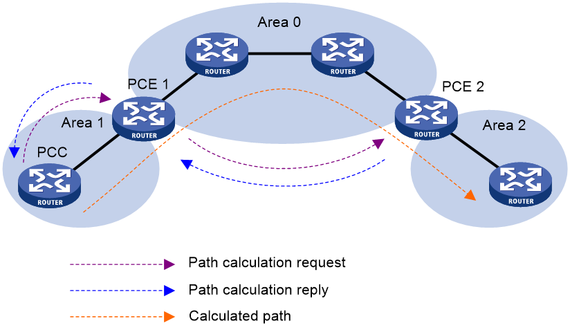
As shown in Figure 1, PCE 1 is the ABR that can calculate paths in Area 0 and Area 1. PCE 2 is the ABR that can calculate paths in Area 1 and Area 2. The CRLSP that PCC uses to reach a destination in Area 2 is established as follows:
1. PCC sends a path calculation request to PCE 1 to request the path to the CRLSP destination.
2. PCE 1 forwards the request to PCE 2.
PCE 1 cannot calculate paths in Area 2, so it forwards the request to PCE 2, the PCE responsible for Area 2 that contains the CRLSP destination.
3. After receiving the request from PCE 1, PCE 2 calculates potential paths to the CRLSP destination and sends the path information back to PCE 1 in a reply.
4. PCE 1 uses the local and received path information to select an end-to-end path for the PCC to reach the CRLSP destination, and sends the path to PCC as a reply.
5. PCC uses the path calculated by PCEs to establish the CRLSP through RSVP-TE.
Figure 1 BRPC path calculation
Traffic forwarding
After an MPLS TE tunnel is established, traffic is not forwarded on the tunnel automatically. You must direct the traffic to the tunnel by using one of the following methods:
Static routing
You can direct traffic to an MPLS TE tunnel by creating a static route that reaches the destination through the tunnel interface. This is the easiest way to implement MPLS TE tunnel forwarding. When traffic to multiple networks is to be forwarded through the MPLS TE tunnel, you must configure multiple static routes, which are complicated to configure and difficult to maintain.
For more information about static routing, see Layer 3—IP Routing Configuration Guide.
Policy-based routing
You can configure PBR on the ingress interface of traffic to direct the traffic that matches an ACL to the MPLS TE tunnel interface.
PBR can match the traffic to be forwarded on the tunnel not only by destination IP address, but also by source IP address, protocol type, and other criteria. Compared with static routing, PBR is more flexible but requires more complicated configuration.
For more information about policy-based routing, see Layer 3—IP Routing Configuration Guide.
Automatic route advertisement
You can also configure automatic route advertisement to forward traffic through an MPLS TE tunnel. Automatic route advertisement distributes the MPLS TE tunnel to the IGP (OSPF or IS-IS), so the MPLS TE tunnel can participate in IGP routing calculation. Automatic route advertisement is easy to configure and maintain.
Automatic route advertisement can be implemented by using the following methods:
· IGP shortcut—Also known as AutoRoute Announce. It considers the MPLS TE tunnel as a link that directly connects the tunnel ingress node and the egress node. Only the ingress node uses the MPLS TE tunnel during IGP route calculation.
· Forwarding adjacency—Considers the MPLS TE tunnel as a link that directly connects the tunnel ingress node and the egress node, and advertises the link to the network through an IGP. Every node in the network uses the MPLS TE tunnel during IGP route calculation.
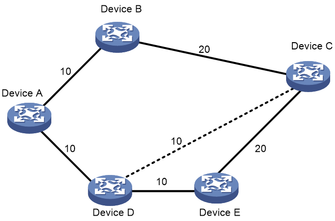
As shown in Figure 2, an MPLS TE tunnel exists from Device D to Device C. IGP shortcut enables only the ingress node Device D to use the MPLS TE tunnel in the IGP route calculation. Device A cannot use this tunnel to reach Device C. With forwarding adjacency enabled, Device A can learn this MPLS TE tunnel and transfer traffic to Device C by forwarding the traffic to Device D.
Figure 2 IGP shortcut and forwarding adjacency diagram
Make-before-break
Make-before-break is a mechanism to change an MPLS TE tunnel with minimum data loss and without using extra bandwidth.
In the case of tunnel reoptimization, traffic forwarding is interrupted if the existing CRLSP is removed before a new CRLSP is established. The make-before-break mechanism ensures that the existing CRLSP is removed after the new CRLSP is established and the traffic is switched to the new CRLSP. However, this wastes bandwidth resources if some links on the old and new CRLSPs are the same. This is because you need to reserve bandwidth on these links for the old and new CRLSPs separately. The make-before-break mechanism uses the SE resource reservation style to address this problem.
The resource reservation style refers to the style in which RSVP-TE reserves bandwidth resources during CRLSP establishment. The resource reservation style used by an MPLS TE tunnel is determined by the ingress node, and is advertised to other nodes through RSVP.
The device supports the following resource reservation styles:
· FF—Fixed-filter, where resources are reserved for individual senders and cannot be shared among senders on the same session.
· SE—Shared-explicit, where resources are reserved for senders on the same session and shared among them. SE is mainly used for make-before-break.
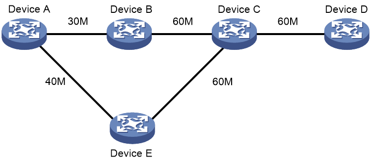
As shown in Figure 3, a CRLSP with 30 M reserved bandwidth has been set up from Device A to Device D through the path Device A—Device B—Device C—Device D.
To increase the reserved bandwidth to 40 M, a new CRLSP must be set up through the path Device A—Device E—Device C—Device D. To achieve this purpose, RSVP-TE needs to reserve 30 M bandwidth for the old CRLSP and 40 M bandwidth for the new CRLSP on the link Device C—Device D. However, there is not enough bandwidth.
After the make-before-break mechanism is used, the new CRLSP can share the bandwidth reserved for the old CRLSP. After the new CRLSP is set up, traffic is switched to the new CRLSP without service interruption, and then the old CRLSP is removed.
Figure 3 Diagram for make-before-break
Route pinning
Route pinning enables CRLSPs to always use the original optimal path even if a new optimal route has been learned.
On a network where route changes frequently occur, you can use route pinning to avoid re-establishing CRLSPs upon route changes.
Tunnel reoptimization
Tunnel reoptimization allows you to manually or dynamically trigger the ingress node to recalculate a path. If the ingress node recalculates a better path, it creates a new CRLSP, switches traffic from the old CRLSP to the new, and then deletes the old CRLSP.
MPLS TE uses the tunnel reoptimization feature to implement dynamic CRLSP optimization. For example, if a link on the optimal path does not have enough reservable bandwidth, MPLS TE sets up the tunnel on another path. When the link has enough bandwidth, the tunnel optimization feature can switch the MPLS TE tunnel to the optimal path.
CRLSP backup
CRLSP backup uses a CRLSP to back up a primary CRLSP. When the ingress detects that the primary CRLSP fails, it switches traffic to the backup CRLSP. When the primary CRLSP recovers, the ingress switches traffic back.
CRLSP backup has the following modes:
· Hot standby—A backup CRLSP is created immediately after a primary CRLSP is created.
· Ordinary—A backup CRLSP is created after the primary CRLSP fails.
FRR
Fast reroute (FRR) protects CRLSPs from link and node failures. FRR can implement 50-millisecond CRLSP failover.
After FRR is enabled for an MPLS TE tunnel, once a link or node fails on the primary CRLSP, FRR reroutes the traffic to a bypass tunnel. The ingress node attempts to set up a new CRLSP. After the new CRLSP is set up, traffic is forwarded on the new CRLSP.
CRLSP backup provides end-to-end path protection for a CRLSP without time limitation. FRR provides quick but temporary protection for a link or node on a CRLSP.
Basic concepts
· Primary CRLSP—Protected CRLSP.
· Bypass tunnel—An MPLS TE tunnel used to protect a link or node of the primary CRLSP.
· Point of local repair—A PLR is the ingress node of the bypass tunnel. It must be located on the primary CRLSP but must not be the egress node of the primary CRLSP.
· Merge point—An MP is the egress node of the bypass tunnel. It must be located on the primary CRLSP but must not be the ingress node of the primary CRLSP.
Protection modes
FRR provides the following protection modes:
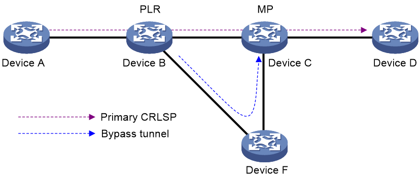
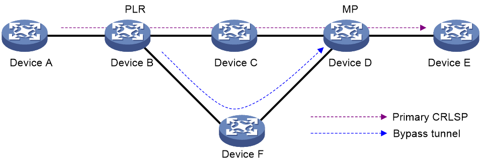
· Link protection—The PLR and the MP are connected through a direct link and the primary CRLSP traverses this link. When the link fails, traffic is switched to the bypass tunnel. As shown in Figure 4, the primary CRLSP is Device A—Device B—Device C—Device D, and the bypass tunnel is Device B—Device F—Device C. This mode is also called next-hop (NHOP) protection.
· Node protection—The PLR and the MP are connected through a device and the primary CRLSP traverses this device. When the device fails, traffic is switched to the bypass tunnel. As shown in Figure 5, the primary CRLSP is Device A—Device B—Device C—Device D—Device E, and the bypass tunnel is Device B—Device F—Device D. Device C is the protected device. This mode is also called next-next-hop (NNHOP) protection.
DiffServ-aware TE
DiffServ is a model that provides differentiated QoS guarantees based on service class. MPLS TE is a traffic engineering solution that focuses on optimizing network resources allocation.
DiffServ-aware TE (DS-TE) combines DiffServ and TE to optimize network resources allocation on a per-service class basis. DS-TE defines different bandwidth constraints for class types. It maps each traffic class type to the CRLSP that is constraint-compliant for the class type.
The device supports the following DS-TE modes:
· Prestandard mode—H3C proprietary DS-TE.
· IETF mode—Complies with RFC 4124, RFC 4125, and RFC 4127.
Basic concepts
· CT—Class Type. DS-TE allocates link bandwidth, implements constraint-based routing, and performs admission control on a per-class type basis. A given traffic flow belongs to the same CT on all links.
· BC—Bandwidth Constraint. BC restricts the bandwidth for one or more CTs.
· Bandwidth constraint model—Algorithm for implementing bandwidth constraints on different CTs. A BC model contains two factors, the maximum number of BCs (MaxBC) and the mappings between BCs and CTs. DS-TE supports two BC models, Russian Dolls Model (RDM) and Maximum Allocation Model (MAM).
· TE class—Defines a CT and a priority. The setup priority or holding priority of an MPLS TE tunnel for a CT must be the same as the priority of the TE class.
The prestandard and IETF modes of DS-TE have the following differences:
· The prestandard mode supports two CTs (CT 0 and CT 1), eight priorities, and a maximum of 16 TE classes. The IETF mode supports four CTs (CT 0 through CT 3), eight priorities, and a maximum of eight TE classes.
· The prestandard mode does not allow you to configure TE classes. The IETF mode allows for TE class configuration.
· The prestandard mode supports only RDM. The IETF mode supports both RDM and MAM.
· A device operating in prestandard mode cannot communicate with devices from some vendors. A device operating in IETF mode can communicate with devices from other vendors.
How DS-TE operates
A device takes the following steps to establish an MPLS TE tunnel for a CT:
1. Determines the CT.
A device classifies traffic according to your configuration:
¡ When configuring a dynamic MPLS TE tunnel, you can use the mpls te bandwidth command on the tunnel interface to specify a CT for the traffic to be forwarded by the tunnel.
¡ When configuring a static MPLS TE tunnel, you can use the bandwidth keyword to specify a CT for the traffic to be forwarded along the tunnel.
2. Verifies that bandwidth is enough for the CT.
You can use the mpls te max-reservable-bandwidth command on an interface to configure the bandwidth constraints of the interface. The device determines whether the bandwidth is enough to establish an MPLS TE tunnel for the CT.
The relation between BCs and CTs varies by BC model.
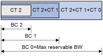
¡ In RDM model, a BC constrains the total bandwidth of multiple CTs, as shown in Figure 6:
- BC 2 is for CT 2. The total bandwidth for CT 2 cannot exceed BC 2.
- BC 1 is for CT 2 and CT 1. The total bandwidth for CT 2 and CT 1 cannot exceed BC 1.
- BC 0 is for CT 2, CT 1, and CT 0. The total bandwidth for CT 2, CT 1, and CT 0 cannot exceed BC 0. In this model, BC 0 equals the maximum reservable bandwidth of the link.
In cooperation with priority preemption, the RDM model can also implement bandwidth isolation between CTs. RDM is suitable for networks where traffic is unstable and traffic bursts might occur.
Figure 6 RDM bandwidth constraints model
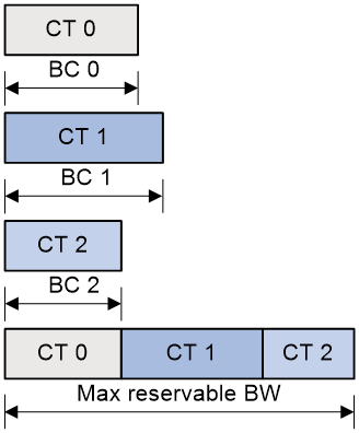
¡ In MAM model, a BC constrains the bandwidth for only one CT. This ensures bandwidth isolation among CTs no matter whether preemption is used or not. Compared with RDM, MAM is easier to configure. MAM is suitable for networks where traffic of each CT is stable and no traffic bursts occur. Figure 7 shows an example:
- BC 0 is for CT 0. The bandwidth occupied by the traffic of CT 0 cannot exceed BC 0.
- BC 1 is for CT 1. The bandwidth occupied by the traffic of CT 1 cannot exceed BC 1.
- BC 2 is for CT 2. The bandwidth occupied by the traffic of CT 2 cannot exceed BC 2.
- The total bandwidth occupied by CT 0, CT 1, and CT 2 cannot exceed the maximum reservable bandwidth.
Figure 7 MAM bandwidth constraints model
3. Verifies that the CT and the LSP setup/holding priority match an existing TE class.
An MPLS TE tunnel can be established for the CT only when the following conditions are met:
¡ Every node along the tunnel has a TE class that matches the CT and the LSP setup priority.
¡ Every node along the tunnel has a TE class that matches the CT and the LSP holding priority.
Bidirectional MPLS TE tunnel
MPLS Transport Profile (MPLS-TP) uses bidirectional MPLS TE tunnels to implement 1:1 and 1+1 protection switching, and to support in-band detection tools and signaling protocols such as OAM and PSC.
A bidirectional MPLS TE tunnel includes a pair of CRLSPs in opposite directions. It can be established in the following modes:
· Co-routed mode—Uses the extended RSVP-TE protocol to establish a bidirectional MPLS TE tunnel. RSVP-TE uses a Path message to advertise the labels assigned by the upstream LSR to the downstream LSR. RSVP-TE uses a Resv message to advertise the labels assigned by the downstream LSR to the upstream LSR. During the delivery of the path message, a CRLSP in one direction is established. During the delivery of the Resv message, a CRLSP in the other direction is established. The CRLSPs of a bidirectional MPLS TE tunnel established in co-routed mode use the same path.
· Associated mode—In this mode, you establish a bidirectional MPLS TE tunnel by binding two unidirectional CRLSPs in opposite directions. The two CRLSPs can be established in different modes and use different paths. For example, one CRLSP is established statically and the other CRLSP is established dynamically by RSVP-TE.
For more information about establishing MPLS TE tunnel through RSVP-TE, the Path message, and the Resv message, see "Configuring RSVP."
CBTS
About this task
Class Based Tunnel Selection (CBTS) enables dynamic routing and forwarding of traffic with different service class values over different MPLS TE tunnels between the same tunnel headend and tailend. Unlike load sharing that selects multiple tunnels to forward the matching traffic, CBTS uses a dedicated tunnel for a certain service class.
How CBTS works
CBTS processes incoming traffic on the device as follows:
1. Uses a traffic behavior to set a service class value for the traffic. For more information about traffic behaviors, see QoS configuration in ACL and QoS Configuration Guide.
2. Compares the service class value of the traffic with the service class values of the MPLS TE tunnels and forwards the traffic to a matching tunnel.
MPLS TE tunnel selection rules
CBTS uses the following rules to select an MPLS TE tunnel for the incoming traffic:
· If the traffic matches an MPLS TE tunnel, CBTS uses this tunnel.
· If the traffic matches multiple MPLS TE tunnels, CBTS randomly selects a matching tunnel.
· If the traffic does not match any MPLS TE tunnels, CBTS randomly selects a tunnel from all tunnels with the lowest priority.
The smaller the service class value, the lower the tunnel priority. An MPLS TE tunnel that is not configured with a service class value has the lowest priority.
CBTS application scenario
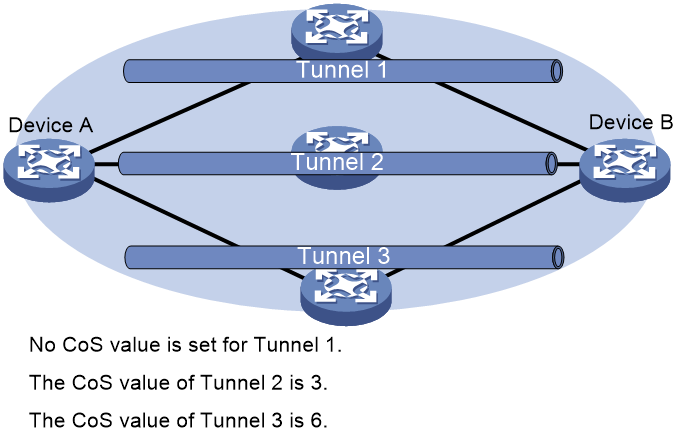
As shown in Figure 8, CBTS selects MPLS TE tunnels for the incoming traffic as follows:
· Uses Tunnel 2 to forward traffic with service class value 3.
· Uses Tunnel 3 to forward traffic with service class value 6.
· Uses Tunnel 1 to forward traffic with no service class value.
Figure 8 CBTS application scenario
MPLS TE P2MP tunnels
MPLS TE P2MP tunnels are automatically established after multicast VPN in RSVP-TE mode is configured. After the MPLS TE P2MP tunnels are established, you can use the display mpls te p2mp tunnel-interface command to display information about the tunnels. For more information about MPLS TE P2MP tunnels, see "Configuring RSVP." For more information about multicast VPN, see IP Multicast Configuration Guide.
Protocols and standards
· RFC 2702, Requirements for Traffic Engineering Over MPLS
· RFC 3564, Requirements for Support of Differentiated Service-aware MPLS Traffic Engineering
· RFC 3812, Multiprotocol Label Switching (MPLS) Traffic Engineering (TE) Management Information Base (MIB)
· RFC 4124, Protocol Extensions for Support of Diffserv-aware MPLS Traffic Engineering
· RFC 4125, Maximum Allocation Bandwidth Constraints Model for Diffserv-aware MPLS Traffic Engineering
· RFC 4127, Russian Dolls Bandwidth Constraints Model for Diffserv-aware MPLS Traffic Engineering
· ITU-T Recommendation Y.1720, Protection switching for MPLS networks
· RFC 4655, A Path Computation Element (PCE)-Based Architecture
· RFC 5088, OSPF Protocol Extensions for Path Computation Element Discovery
· RFC 5440, Path Computation Element (PCE) Communication Protocol (PCEP)
· RFC 5441, A Backward-Recursive PCE-Based Computation (BRPC) Procedure to Compute Shortest Constrained Inter-Domain Traffic Engineering LSP
· RFC 5455, Diffserv-Aware Class-Type Object for the Path Computation Element Communication Protocol
· RFC 5521, Extensions to the Path Computation Element Communication Protocol (PCEP) for Route Exclusions
· RFC 5886, A Set of Monitoring Tools for Path Computation Element (PCE)-Based Architecture
· draft-ietf-pce-stateful-pce-07
Restrictions: Hardware compatibility with MPLS TE
|
Hardware |
MPLS TE compatibility |
|
MSR810, MSR810-W, MSR810-W-DB, MSR810-LM, MSR810-W-LM, MSR810-10-PoE, MSR810-LM-HK, MSR810-W-LM-HK, MSR810-LM-CNDE-SJK, MSR810-CNDE-SJK |
Yes |
|
MSR810-LMS, MSR810-LUS |
No |
|
MSR810-LMS-EA, MSR810-LME |
Yes |
|
MSR2600-6-X1, MSR2600-10-X1 |
Yes |
|
MSR 2630 |
Yes |
|
MSR3600-28, MSR3600-51 |
Yes |
|
MSR3600-28-SI, MSR3600-51-SI |
No |
|
MSR3600-28-X1, MSR3600-28-X1-DP, MSR3600-51-X1, MSR3600-51-X1-DP |
Yes |
|
MSR3610-I-DP, MSR3610-IE-DP, MSR3610-IE-ES, MSR3610-IE-EAD |
Yes |
|
MSR3610-X1, MSR3610-X1-DP, MSR3610-X1-DC, MSR3610-X1-DP-DC |
Yes |
|
MSR 3610, MSR 3620, MSR 3620-DP, MSR 3640, MSR 3660 |
Yes |
|
MSR3610-G, MSR3620-G |
Yes |
|
Hardware |
MPLS TE compatibility |
|
MSR810-W-WiNet, MSR810-LM-WiNet |
Yes |
|
MSR830-4LM-WiNet |
Yes |
|
MSR830-5BEI-WiNet, MSR830-6EI-WiNet, MSR830-10BEI-WiNet |
Yes |
|
MSR830-6BHI-WiNet, MSR830-10BHI-WiNet |
Yes |
|
MSR2600-6-WiNet, MSR2600-10-X1-WiNet |
Yes |
|
MSR2630-WiNet |
Yes |
|
MSR3600-28-WiNet |
Yes |
|
MSR3610-X1-WiNet |
Yes |
|
MSR3610-WiNet, MSR3620-10-WiNet, MSR3620-DP-WiNet, MSR3620-WiNet, MSR3660-WiNet |
Yes |
|
Hardware |
MPLS TE compatibility |
|
MSR2630-XS |
Yes |
|
MSR3600-28-XS |
Yes |
|
MSR3610-XS |
Yes |
|
MSR3620-XS |
Yes |
|
MSR3610-I-XS |
Yes |
|
MSR3610-IE-XS |
Yes |
|
Hardware |
MPLS TE compatibility |
|
MSR810-LM-GL |
Yes |
|
MSR810-W-LM-GL |
Yes |
|
MSR830-6EI-GL |
Yes |
|
MSR830-10EI-GL |
Yes |
|
MSR830-6HI-GL |
Yes |
|
MSR830-10HI-GL |
Yes |
|
MSR2600-6-X1-GL |
Yes |
|
MSR3600-28-SI-GL |
No |
MPLS TE tasks at a glance
Establishing a static CRLSP
Perform this task on all nodes and interfaces that the MPLS TE tunnel traverses.
2. Configuring a tunnel interface
Perform this task on the ingress node of the MPLS TE tunnel.
3. (Optional.) Configuring DS-TE
This task is configurable on all nodes that the MPLS TE tunnel traverses.
4. Establishing a static CRLSP
This task is required on all nodes that the MPLS TE tunnel traverses.
For more information, see "Configuring a static CRLSP."
5. Configuring an MPLS TE tunnel to use a static CRLSP
Perform this task on the ingress node of the MPLS TE tunnel.
6. (Optional.) Configuring unequal load sharing for an MPLS TE tunnel
Perform this task on the ingress node of the MPLS TE tunnel.
7. Configuring traffic forwarding
Choose one of the following tasks:
¡ Configuring static routing to direct traffic to an MPLS TE tunnel or tunnel bundle
¡ Configuring PBR to direct traffic to an MPLS TE tunnel
¡ Configuring automatic route advertisement to direct traffic to an MPLS TE tunnel
Perform the tasks on the ingress node of the MPLS TE tunnel.
8. (Optional.) Configuring a bidirectional MPLS TE tunnel
Perform this task on the ingress node and egress node of the MPLS TE tunnel.
9. (Optional.) Configuring CBTS
10. (Optional.) Enabling SNMP notifications for MPLS TE
Establishing a CRLSP dynamically
1. Enabling MPLS TE and RSVP
¡ Enabling RSVP
For more information about enabling RSVP, see "Configuring RSVP."
Perform this task on all nodes and interfaces that the MPLS TE tunnel traverses.
2. Configuring a tunnel interface
Perform this task on the ingress node of the MPLS TE tunnel.
3. (Optional.) Configuring DS-TE
This task is configurable on all nodes that the MPLS TE tunnel traverses.
4. Configuring an MPLS TE tunnel to use a CRLSP dynamically established by RSVP-TE
a. Configuring MPLS TE attributes for a link
Perform this task on all nodes that the MPLS TE tunnel traverses.
b. Advertising link TE attributes by using IGP TE extension
Perform this task on all nodes that the MPLS TE tunnel traverses.
c. Configuring MPLS TE tunnel constraints
Perform this task on the ingress node of the MPLS TE tunnel.
d. Establishing an MPLS TE tunnel by using RSVP-TE
Perform this task on the ingress node of the MPLS TE tunnel.
e. (Optional.) Controlling CRLSP path selection
f. (Optional.) Controlling MPLS TE tunnel setup
Perform this task on the ingress node of the MPLS TE tunnel.
5. (Optional.) Configuring unequal load sharing for an MPLS TE tunnel
Perform this task on the ingress node of the MPLS TE tunnel.
6. Configuring traffic forwarding
Choose one of the following tasks:
¡ Configuring static routing to direct traffic to an MPLS TE tunnel or tunnel bundle
¡ Configuring PBR to direct traffic to an MPLS TE tunnel
¡ Configuring automatic route advertisement to direct traffic to an MPLS TE tunnel
Perform the tasks on the ingress node of the MPLS TE tunnel.
7. (Optional.) Configuring a bidirectional MPLS TE tunnel
Perform this task on the ingress node and egress node of the MPLS TE tunnel.
8. (Optional.) Enhancing MPLS TE availability
Perform this task on the ingress node of the MPLS TE tunnel.
Enable FRR on the ingress node of the primary CRLSP.
9. (Optional.) Configuring CBTS
10. (Optional.) Enabling SNMP notifications for MPLS TE
Establishing a CRLSP by using the path calculated by PCEs
1. Enabling MPLS TE and RSVP
¡ Enabling RSVP
For more information about enabling RSVP, see "Configuring RSVP."
Perform this task on all nodes and interfaces that the MPLS TE tunnel traverses.
2. Configuring a tunnel interface
Perform this task on the ingress node of the MPLS TE tunnel.
3. (Optional.) Configuring DS-TE
This task is configurable on all nodes that the MPLS TE tunnel traverses.
4. Configuring an MPLS TE tunnel to use a CRLSP dynamically established by RSVP-TE
a. Configuring MPLS TE attributes for a link
Perform this task on all nodes that the MPLS TE tunnel traverses.
b. Advertising link TE attributes by using IGP TE extension
Perform this task on all nodes that the MPLS TE tunnel traverses.
c. Configuring MPLS TE tunnel constraints
Perform this task on the ingress node of the MPLS TE tunnel.
5. Configuring an MPLS TE tunnel to use a CRLSP calculated by PCEs
Perform this task on a device that acts as a PCE, regardless of whether the device is on the MPLS TE tunnel.
Perform this task on PCCs.
c. Establishing a CRLSP by using the path calculated by PCEs
Perform this task on PCCs.
d. Establishing an MPLS TE tunnel by using RSVP-TE
Perform this task on the ingress node of the MPLS TE tunnel.
e. Configuring stateful PCE on a PCC
Perform this task on PCCs.
f. Configuring PCEP session parameters
Perform this task on PCCs.
6. (Optional.) Configuring unequal load sharing for an MPLS TE tunnel
Perform this task on the ingress node of the MPLS TE tunnel.
7. Configuring traffic forwarding
Choose one of the following tasks:
¡ Configuring static routing to direct traffic to an MPLS TE tunnel or tunnel bundle
¡ Configuring PBR to direct traffic to an MPLS TE tunnel
¡ Configuring automatic route advertisement to direct traffic to an MPLS TE tunnel
Perform the tasks on the ingress node of the MPLS TE tunnel.
8. (Optional.) Configuring a bidirectional MPLS TE tunnel
Perform this task on the ingress node and egress node of the MPLS TE tunnel.
9. (Optional.) Enhancing MPLS TE availability
Perform this task on the ingress node of the MPLS TE tunnel.
Enable FRR on the ingress node of the primary CRLSP.
10. (Optional.) Configuring CBTS
11. (Optional.) Enabling SNMP notifications for MPLS TE
Prerequisites for MPLS TE
Before you enable MPLS TE, perform the following tasks:
· Configure static routing or IGP to ensure that all LSRs can reach each other.
· Enable MPLS. For information about enabling MPLS, see "Configuring basic MPLS."
Enabling MPLS TE
1. Enter system view.
system-view
2. Enable MPLS TE on the node and enter MPLS TE view.
mpls te
By default, MPLS TE is disabled.
3. Return to system view.
quit
4. Enter interface view.
interface interface-type interface-number
5. Enable MPLS TE for the interface.
mpls te enable
By default, MPLS TE is disabled on an interface.
Configuring a tunnel interface
About this task
To configure an MPLS TE tunnel, you must create an MPLS TE tunnel interface and enter tunnel interface view. All MPLS TE tunnel attributes are configured in tunnel interface view. For more information about tunnel interfaces, see tunneling configuration in Layer 3—IP Services Configuration Guide.
Perform this task on the ingress node of the MPLS TE tunnel.
Restrictions and guidelines
On an up MPLS TE tunnel interface, perform the following operations with caution because they can cause interface down/up flappings:
· Modifying the affinity attribute of the MPLS TE tunnel.
· Modifying the setup priority and holding priority of the MPLS TE tunnel.
· Modifying the MPLS TE tunnel configuration when the resources reservation style is FF.
· Modifying the MPLS TE tunnel configuration when the tunnel is a bidirectional MPLS TE tunnel.
· Modifying the CT of the MPLS TE tunnel.
· Specifying a primary or backup traffic processing slot for the tunnel interface.
· Restarting or swapping the specified primary or backup traffic processing slot.
For more information about specifying traffic processing slots for an interface, see tunneling configuration in Layer 3—IP Services Configuration Guide.
Procedure
1. Enter system view.
system-view
2. Create an MPLS TE tunnel interface and enter tunnel interface view.
interface tunnel tunnel-number mode mpls-te
3. Configure an IP address for the tunnel interface.
ip address ip-address { mask-length | mask }
By default, a tunnel interface does not have an IP address.
4. Specify the tunnel destination address.
destination ip-address
By default, no tunnel destination address is specified.
Configuring DS-TE
About this task
DS-TE is configurable on any node that an MPLS TE tunnel traverses.
Procedure
1. Enter system view.
system-view
2. Enter MPLS TE view.
mpls te
3. Configure the DS-TE mode.
¡ Configure the DS-TE mode as IETF.
ds-te mode ietf
¡ Configure the DS-TE mode as prestandard.
undo ds-te mode ietf
By default, the DS-TE mode is prestandard.
4. Configure the BC model of IETF DS-TE.
¡ Configure the BC model of IETF DS-TE as MAM.
ds-te bc-model mam
¡ Configure the BC model of IETF DS-TE as RDM.
undo ds-te bc-model mam
By default, the BC model of IETF DS-TE is RDM.
5. Configure a TE class used in IETF DS-TE mode.
ds-te te-class te-class-index class-type class-type-number priority priority
The default TE classes for IETF mode are shown in Table 1.
Table 1 Default TE classes in IETF mode
|
TE Class |
CT |
Priority |
|
0 |
0 |
7 |
|
1 |
1 |
7 |
|
2 |
2 |
7 |
|
3 |
3 |
7 |
|
4 |
0 |
0 |
|
5 |
1 |
0 |
|
6 |
2 |
0 |
|
7 |
3 |
0 |
Configuring an MPLS TE tunnel to use a static CRLSP
About this task
Perform this task on the ingress node of the MPLS TE tunnel.
Procedure
1. Enter system view.
system-view
2. Enter MPLS TE tunnel interface view.
interface tunnel tunnel-number [ mode mpls-te ]
3. Specify the MPLS TE tunnel establishment mode as static.
mpls te signaling static
By default, MPLS TE uses RSVP-TE to establish a tunnel.
4. Apply the static CRLSP to the tunnel interface.
mpls te static-cr-lsp lsp-name
By default, a tunnel does not use any static CRLSP.
Make sure the static CRLSP already exists. For more information about configuring a static CRLSP, see "Configuring a static CRLSP."
Configuring MPLS TE attributes for a link
1. Enter system view.
system-view
2. Enter interface view.
interface interface-type interface-number
3. Set the maximum link bandwidth for MPLS TE traffic.
mpls te max-link-bandwidth bandwidth-value
By default, the maximum link bandwidth for MPLS TE traffic is 0.
4. Set the maximum reservable bandwidth. Use one of the following methods according to the DS-TE mode and BC model configured in "Configuring DS-TE."
¡ Configure the maximum reservable bandwidth of the link (BC 0) and BC 1 in RDM model of the prestandard DS-TE.
mpls te max-reservable-bandwidth bandwidth-value [ bc1 bc1-bandwidth ]
¡ Configure the maximum reservable bandwidth of the link and the BCs in MAM model of the IETF DS-TE.
mpls te max-reservable-bandwidth mam bandwidth-value { bc0 bc0-bandwidth | bc1 bc1-bandwidth | bc2 bc2-bandwidth | bc3 bc3-bandwidth } *
¡ Configure the maximum reservable bandwidth of the link and the BCs in RDM model of the IETF DS-TE.
mpls te max-reservable-bandwidth rdm bandwidth-value [ bc1 bc1-bandwidth ] [ bc2 bc2-bandwidth ] [ bc3 bc3-bandwidth ]
By default, the maximum reservable bandwidth of a link is 0 kbps and each BC is 0 kbps.
In RDM model, BC 0 is the maximum reservable bandwidth of a link.
5. Set the link attribute.
mpls te link-attribute attribute-value
By default, the link attribute value is 0x00000000.
Advertising link TE attributes by using IGP TE extension
About IGP TE extension
Both OSPF and IS-IS are extended to advertise link TE attributes. The extensions are called OSPF TE and IS-IS TE. If both OSPF TE and IS-IS TE are available, OSPF TE takes precedence.
Restrictions and guidelines for advertising link TE attributes by using IGP TE extension
You must configure the IGP TE extension to establish a TEDB. Otherwise, the path is created based on IGP routing rather than computed by CSPF.
Configuring OSPF TE
About this task
OSPF TE uses Type-10 opaque LSAs to carry the TE attributes for a link. Before you configure OSPF TE, you must enable opaque LSA advertisement and reception by using the opaque-capability enable command. For more information about opaque LSA advertisement and reception, see OSPF configuration in Layer 3—IP Routing Configuration Guide.
Restrictions and guidelines
MPLS TE cannot reserve resources and distribute labels for an OSPF virtual link, and cannot establish a CRLSP through an OSPF virtual link. Therefore, make sure no virtual link exists in an OSPF area before you configure MPLS TE.
Procedure
1. Enter system view.
system-view
2. Enter OSPF view.
ospf [ process-id ]
3. Enable opaque LSA advertisement and reception.
opaque-capability enable
By default, opaque LSA advertisement and reception are enabled.
For more information about this command, see OSPF commands in Layer 3—IP Routing Command Reference.
4. Enter area view.
area area-id
5. Enable MPLS TE for the OSPF area.
mpls te enable
By default, MPLS TE is disabled for an OSPF area.
Configuring IS-IS TE
About this task
IS-IS TE uses a sub-TLV of the extended IS reachability TLV (type 22) to carry TE attributes. Because the extended IS reachability TLV carries wide metrics, specify a wide metric-compatible metric style for the IS-IS process before enabling IS-IS TE. Available metric styles for IS-IS TE include wide, compatible, or wide-compatible. For more information about IS-IS, see IS-IS configuration in Layer 3—IP Routing Configuration Guide.
Restrictions and guidelines
On IS-IS enabled interfaces, set the MTU to a minimum of 512 bytes to ensure that IS-IS LSPs of different lengths can be flooded to the network.
Procedure
1. Enter system view.
system-view
2. Create an IS-IS process and enter IS-IS view.
isis [ process-id ]
By default, no IS-IS process exists.
3. Specify a metric style.
cost-style { narrow | wide | wide-compatible | { compatible | narrow-compatible } [ relax-spf-limit ] }
By default, only narrow metric style packets can be received and sent.
For more information about this command, see IS-IS commands in Layer 3—IP Routing Command Reference.
4. Enable MPLS TE for the IS-IS process.
mpls te enable [ Level-1 | Level-2 ]
By default, MPLS TE is disabled for an IS-IS process.
5. Specify the types of the sub-TLVs for carrying DS-TE parameters.
te-subtlv { bw-constraint value | unreserved-subpool-bw value } *
By default, the bw-constraint parameter is carried in sub-TLV 252, and the unreserved-bw-sub-pool parameter is carried in sub-TLV 251.
Configuring MPLS TE tunnel constraints
Configuring bandwidth constraints for an MPLS TE tunnel
1. Enter system view.
system-view
2. Enter MPLS TE tunnel interface view.
interface tunnel tunnel-number [ mode mpls-te ]
3. Configure bandwidth required for the tunnel, and specify a CT for the tunnel's traffic.
mpls te bandwidth [ ct0 | ct1 | ct2 | ct3 ] bandwidth
By default, no bandwidth is assigned, and the class type is CT 0.
Configuring the affinity attribute for an MPLS TE tunnel
About this task
The associations between the link attribute and the affinity attribute might vary by vendor. To ensure the successful establishment of a tunnel between two devices from different vendors, correctly configure their respective link attribute and affinity attribute.
Procedure
1. Enter system view.
system-view
2. Enter MPLS TE tunnel interface view.
interface tunnel tunnel-number [ mode mpls-te ]
3. Set an affinity for the MPLS TE tunnel.
mpls te affinity-attribute attribute-value [ mask mask-value ]
By default, the affinity is 0x00000000, and the mask is 0x00000000. The default affinity matches all link attributes.
Setting a setup priority and a holding priority for an MPLS TE tunnel
1. Enter system view.
system-view
2. Enter MPLS TE tunnel interface view.
interface tunnel tunnel-number [ mode mpls-te ]
3. Set a setup priority and a holding priority for the MPLS TE tunnel.
mpls te priority setup-priority [ hold-priority ]
By default, the setup priority and the holding priority are both 7 for an MPLS TE tunnel.
Configuring an explicit path for an MPLS TE tunnel
About this task
An explicit path is a set of nodes. The relationship between any two neighboring nodes on an explicit path can be either strict or loose.
· Strict—The two nodes must be directly connected.
· Loose—The two nodes can have devices in between.
Restrictions and guidelines
When establishing an MPLS TE tunnel between areas or ASs, you must perform the following tasks:
· Use a loose explicit path.
· Specify the ABR or ASBR as the next hop of the explicit path.
· Make sure the tunnel's ingress node and the ABR or ASBR can reach each other.
Procedure
1. Enter system view.
system-view
2. Create an explicit path and enter its view.
explicit-path path-name
3. Enable the explicit path.
undo disable
By default, an explicit path is enabled.
4. Add or modify a node in the explicit path.
nexthop [ index index-number ] ip-address [ exclude | include [ loose | strict ] ]
By default, an explicit path does not include any node.
You can specify the include keyword to have the CRLSP traverse the specified node or the exclude keyword to have the CRLSP bypass the specified node.
5. Return to system view.
quit
6. Enter MPLS TE tunnel interface view.
interface tunnel tunnel-number [ mode mpls-te ]
7. Configure the MPLS TE tunnel interface to use the explicit path, and specify a preference value for the explicit path.
mpls te path preference value explicit-path path-name [ no-cspf ]
By default, MPLS TE uses the calculated path to establish a CRLSP.
Establishing an MPLS TE tunnel by using RSVP-TE
1. Enter system view.
system-view
2. Enter MPLS TE tunnel interface view.
interface tunnel tunnel-number [ mode mpls-te ]
3. Configure MPLS TE to use RSVP-TE to establish the tunnel.
mpls te signaling rsvp-te
By default, MPLS TE uses RSVP-TE to establish a tunnel.
4. Specify an explicit path for the MPLS TE tunnel, and specify the path preference value.
mpls te path preference value { dynamic | explicit-path path-name } [ no-cspf ]
By default, MPLS TE uses the calculated path to establish a CRLSP.
Controlling CRLSP path selection
About CRLSP path selection
MPLS TE uses CSPF to calculate a path according to the TEDB and constraints and sets up the CRLSP through RSVP-TE. MPLS TE provides measures that affect the CSPF calculation. You can use these measures to tune the path selection for CRLSP.
Restrictions and guidelines for CRLSP path selection control
Before performing the configuration tasks in this section, be aware of each configuration objective and its impact on your device.
Configuring the metric type for path selection
About this task
Each MPLS TE link has two metrics: IGP metric and TE metric. By planning the two metrics, you can select different tunnels for different classes of traffic. For example, use the IGP metric to represent a link delay (a smaller IGP metric value indicates a lower link delay), and use the TE metric to represent a link bandwidth value (a smaller TE metric value indicates a bigger link bandwidth value).
You can establish two MPLS TE tunnels: Tunnel 1 for voice traffic and Tunnel 2 for video traffic. Configure Tunnel 1 to use IGP metrics for path selection, and configure Tunnel 2 to use TE metrics for path selection. As a result, the video service (with larger traffic) travels through the path that has larger bandwidth, and the voice traffic travels through the path that has lower delay.
The metric type can be explicitly specified for path selection of a tunnel or globally specified. To specify a global metric type, perform the task on the ingress node of the tunnels. To specify a metric type for a tunnel, perform the task on the tunnel interface. The metric type for a tunnel takes precedence over the global setting.
Configuring the global metric type for tunnel path selection
1. Enter system view.
system-view
2. Enter MPLS TE view.
mpls te
3. Specify the global metric type for tunnel path selection.
path-metric-type { igp | te }
By default, a tunnel uses TE metrics of links for path selection when no global metric type is specified.
Configuring the metric type for path selection of a tunnel
1. Enter system view.
system-view
2. Enter MPLS TE tunnel interface view.
interface tunnel tunnel-number [ mode mpls-te ]
3. Specify the metric type for path selection.
mpls te path-metric-type { igp | te }
By default, no link metric type is specified for the tunnel and the tunnel uses the global metric type.
Assigning a TE metric to a link
1. Enter system view.
system-view
2. Enter interface view.
interface interface-type interface-number
3. Assign a TE metric to the link.
mpls te metric value
By default, the link uses its IGP metric as the TE metric.
This command is available on every interface that the MPLS TE tunnel traverses.
Configuring route pinning
About this task
Perform this task on the ingress node of an MPLS TE tunnel.
Restrictions and guidelines
When route pinning is enabled, MPLS TE tunnel reoptimization is not available.
Procedure
1. Enter system view.
system-view
2. Enter MPLS TE tunnel interface view.
interface tunnel tunnel-number [ mode mpls-te ]
3. Enable route pinning.
mpls te route-pinning
By default, route pinning is disabled.
Configuring tunnel reoptimization
About this task
Perform this task on the ingress node of an MPLS TE tunnel. This feature allows you to manually or dynamically trigger the ingress node to recalculate a path. If the ingress node recalculates a better path, it creates a new CRLSP, switches the traffic from the old CRLSP to the new CRLSP, and then deletes the old CRLSP.
Procedure
1. Enter system view.
system-view
2. Enter MPLS TE tunnel interface view.
interface tunnel tunnel-number [ mode mpls-te ]
3. Enable tunnel reoptimization.
mpls te reoptimization [ frequency seconds ]
By default, tunnel reoptimization is disabled.
4. (Optional.) Immediately reoptimize all MPLS TE tunnels that are enabled with the tunnel reoptimization feature:
a. Return to user view.
return
b. Immediately reoptimize all MPLS TE tunnels that are enabled with the tunnel reoptimization feature.
mpls te reoptimization
Setting TE flooding thresholds and interval
About this task
This task is configurable on all nodes that the MPLS TE tunnel traverses.
When the bandwidth of an MPLS TE link changes, IGP floods the new bandwidth information, so the ingress node can use CSPF to recalculate the path.
To prevent such recalculations from consuming too many resources, you can configure IGP to flood only significant bandwidth changes by setting the following flooding thresholds:
· Up threshold—When the percentage of the reservable-bandwidth increase to the maximum reservable bandwidth reaches the threshold, IGP floods the TE information.
· Down threshold—When the percentage of the reservable-bandwidth decrease to the maximum reservable bandwidth reaches the threshold, IGP floods the TE information.
You can also set the flooding interval at which bandwidth changes that cannot trigger immediate flooding are flooded.
Procedure
1. Enter system view.
system-view
2. Enter interface view.
interface interface-type interface-number
3. Set the bandwidth up/down threshold for the IGP to flood TE information.
mpls te bandwidth change thresholds { down | up } percent
By default, the up/down threshold is 10% of the link reservable bandwidth.
4. Return to system view.
quit
5. Enter MPLS TE view.
mpls te
6. Set the flooding interval.
link-management periodic-flooding timer interval
By default, the flooding interval is 180 seconds.
Controlling MPLS TE tunnel setup
About MPLS TE tunnel setup control
Perform the tasks on the ingress node of an MPLS TE tunnel.
Restrictions and guidelines for MPLS TE tunnel setup control
When you perform the tasks, be aware of each configuration objective and its impact on your device.
Enabling loop detection
About this task
Enabling loop detection also enables the route recording feature, regardless of whether you have configured the mpls te record-route command. Loop detection enables each node of the tunnel to detect whether a loop has occurred according to the recorded route information.
Procedure
1. Enter system view.
system-view
2. Enter MPLS TE tunnel interface view.
interface tunnel tunnel-number [ mode mpls-te ]
3. Enable loop detection.
mpls te loop-detection
By default, loop detection is disabled.
Enabling route and label recording
About this task
Perform this task to record the nodes that an MPLS TE tunnel traverses and the label assigned by each node. The recorded information helps you know about the path used by the MPLS TE tunnel and the label distribution information, and when the tunnel fails, it helps you locate the fault.
Procedure
1. Enter system view.
system-view
2. Enter MPLS TE tunnel interface view.
interface tunnel tunnel-number [ mode mpls-te ]
3. Record routes or record both routes and labels.
¡ Record routes.
mpls te record-route
¡ Record both routes and labels.
mpls te record-route label
By default, both route recording and label recording are disabled.
Setting tunnel setup retry
About this task
If the ingress node fails to establish an MPLS TE tunnel, it waits for the retry interval, and then tries to set up the tunnel again. It repeats this process until the tunnel is established or until the number of attempts reaches the maximum. If the tunnel cannot be established when the number of attempts reaches the maximum, the ingress waits for a longer period and then repeats the previous process.
Procedure
1. Enter system view.
system-view
2. Enter MPLS TE tunnel interface view.
interface tunnel tunnel-number [ mode mpls-te ]
3. Set the maximum number of tunnel setup attempts.
mpls te retry retries
By default, the maximum number of attempts is 3.
4. Set the retry interval.
mpls te timer retry seconds
By default, the retry interval is 2 seconds.
Configuring RSVP resource reservation style
1. Enter system view.
system-view
2. Enter MPLS TE tunnel interface view.
interface tunnel tunnel-number [ mode mpls-te ]
3. Configure the resources reservation style for the tunnel.
mpls te resv-style { ff | se }
By default, the resource reservation style is SE.
In current MPLS TE applications, tunnels are established usually by using the make-before-break mechanism. As a best practice, use the SE style.
Configuring an MPLS TE tunnel to use a CRLSP calculated by PCEs
Configuring a PCE
About this task
An LSR acts as a PCC if no PCE IP address is specified for it. It uses its LSR ID to communicate with PCEs. To configure the LSR as a PCE, perform this task.
Procedure
1. Enter system view.
system-view
2. Enter MPLS TE view.
mpls te
3. Configure a PCE IP address.
pce address ip-address
By default, no PCE address is configured.
Discovering PCEs
About this task
A PCE can be manually specified on a PCC by using the pce static command or automatically discovered through the PCE information advertised by OSPF TE. A PCC sends PCEP connection requests to discovered PCEs but does not accept requests from the PCEs.
Manually specifying a PCE
1. Enter system view.
system-view
2. Enter MPLS TE view.
mpls te
3. Specify the IP address of the PCE.
pce static ip-address
Dynamically discovering PCEs
OSPF TE advertises PCE IP addresses for PCCs and other PCEs to dynamically discover the PCEs and establish PCEP sessions to them. For OSPF TE configuration, see "Configuring OSPF TE."
Establishing a CRLSP by using the path calculated by PCEs
About this task
If you configure the mpls te path command for an LSR, it uses the path calculated by PCEs to establish a CRLSP. The LSR acts as a PCC.
If you specify PCE addresses by using the mpls te path or mpls te backup-path command, the LSR establishes PCEP sessions to the specified PCEs. If you do not specify any PCE addresses, the LSR establishes PCEP sessions to all discovered PCEs.
Procedure
1. Enter system view.
system-view
2. Enter MPLS TE tunnel interface view.
interface tunnel tunnel-number [ mode mpls-te ]
3. Establish a CRLSP by using the path calculated by PCEs.
mpls te path preference value dynamic pce [ ip-address ]&<0-8>
By default, the automatically calculated path is used to establish a CRLSP.
Configuring stateful PCE on a PCC
About this task
For a PCC and a PCE to establish a stateful PCEP session, you must specify the same device type (active stateful or passive stateful) for the two devices.
· If they are configured as passive-stateful devices, the PCE knows all CRLSPs maintained by the PCC but does not accept delegation requests sent by the PCC.
· If they are configured as active-stateful devices, the PCC can delegate CRLSPs to the PCE. If multiple PCEs are available for CRLSP delegation in the network, the PCC chooses the PCE with the highest delegation priority.
If a PCEP session between a PCC and a PCE terminates, the PCC waits for the redelegation timeout interval before it redelegates the CRLSP. If the PCEP session is re-established within the redelegation timeout interval, the PCC redelegates the CRLSP to the PCE. If the PCEP session fails to be re-established within the interval, the PCC redelegates the CRLSP to the PCE that has the second highest delegation priority.
If the redelegation fails and the CRLSP state timeout expires, the PCC uses the path calculated locally to establish the CRLSP.
Procedure
1. Enter system view.
system-view
2. Enter MPLS TE view.
mpls te
3. Configure the PCEP device type as active stateful or passive stateful.
pcep type { active-stateful | passive-stateful }
By default, the PCEP device type is stateless.
4. Set the delegation priority of a PCE.
pce peer ip-address delegation-priority priority
By default, the delegation priority of a PCE is 65535.
A smaller value represents a higher priority.
5. Set the redelegation timeout interval.
pce redelegation-timeout value
By default, the redelegation timeout interval is 30 seconds.
6. Set the CRLSP state timeout interval.
pce state-timeout value
By default, the CRLSP state timeout interval is 60 seconds.
The CRLSP state timeout interval must be equal to or greater than the redelegation timeout interval.
7. Return to MPLS TE view.
quit
8. Enter MPLS TE tunnel interface view.
interface tunnel tunnel-number [ mode mpls-te ]
9. Enable CRLSP delegation.
mpls te delegation
By default, CRLSP delegation is disabled.
Configuring PCEP session parameters
About this task
This task allows you to configure parameters for PCCs or PCEs to establish PCEP sessions to manually specified or dynamically discovered PCEs.
Procedure
1. Enter system view.
system-view
2. Enter MPLS TE view.
mpls te
3. Set the path calculation request timeout time.
pce request-timeout value
By default, the request timeout time is 10 seconds.
4. Set the PCEP session deadtimer.
pce deadtimer value
By default, the PCEP session deadtimer is 120 seconds.
5. Set the keepalive interval for PCEP sessions.
pce keepalive interval
By default, the keepalive interval is 30 seconds.
6. Set the minimum acceptable keepalive interval and the maximum number of allowed unknown messages received from the peer.
pce tolerance { min-keepalive value | max-unknown-messages value }
By default, the minimum acceptable keepalive interval is 10 seconds, and the maximum number of allowed unknown messages in a minute is 5.
Configuring unequal load sharing for an MPLS TE tunnel
About this task
MPLS TE tunnel unequal load sharing specifies multiple member interfaces (MPLS TE tunnel interfaces) for a tunnel bundle interface in load sharing mode. The member interfaces form an MPLS TE tunnel bundle. When the outgoing interface is the tunnel bundle interface, traffic is shared on the member interfaces in proportion of their weights.
For example, a tunnel bundle interface has three member interfaces. The weights for the member interfaces are 1, 1, and 2, respectively. The proportions of traffic forwarded by the member interfaces are 1/4, 1/4, and 1/2, respectively. If you configure the weights for the member interfaces as 2, 2, and 4, the traffic forwarding proportions of the member interfaces are still 1/4, 1/4, and 1/2, respectively
Perform this task on the ingress node of the MPLS TE tunnel.
Restrictions and guidelines
As a best practice, configure the same destination address for a tunnel bundle interface and its member interfaces. Otherwise, traffic cannot be forwarded unless the tunnel bundle interface's destination address can be reached through the member interfaces.
Procedure
1. Enter system view.
system-view
2. Create a tunnel bundle interface and enter tunnel bundle interface view.
interface tunnel-bundle number
3. Configure an IP address for the tunnel bundle interface.
ip address ip-address { mask-length | mask }
By default, no IP address is configured for a tunnel bundle interface.
4. Configure the destination address for the tunnel bundle interface.
destination ip-address
By default, no destination address is configured for a tunnel bundle interface.
5. Specify a member interface for the tunnel bundle interface.
member interface tunnel tunnel-number [ load-share value ]
By default, no member interface is configured for a tunnel bundle interface.
You can execute this command multiple times to specify more member interfaces.
Configuring traffic forwarding
Configuring static routing to direct traffic to an MPLS TE tunnel or tunnel bundle
Creating a static route to direct traffic to an MPLS TE tunnel/tunnel bundle
1. Enter system view.
system-view
2. Configure a static route to direct traffic to an MPLS TE tunnel.
ip route-static { dest-address { mask-length | mask } | group group-name } { interface-type interface-number [ next-hop-address ] [ backup-interface interface-type interface-number [ backup-nexthop backup-nexthop-address ] [ permanent ] | bfd { control-packet | echo-packet } | permanent | track track-entry-number ] | next-hop-address [ bfd control-packet bfd-source ip-address | permanent | track track-entry-number ] | vpn-instance d-vpn-instance-name next-hop-address [ bfd control-packet bfd-source ip-address | permanent | track track-entry-number ] } [ preference preference ] [ tag tag-value ] [ description text ]
The interface specified in this command must be an MPLS TE tunnel interface or an MPLS TE tunnel bundle interface.
For more information about this command, see static routing commands in Layer 3—IP Routing Command Reference.
Configuring automatic static route advertisement to direct traffic to an MPLS TE tunnel
1. Enter system view.
system-view
2. Enter MPLS TE tunnel view.
interface tunnel tunnel-number [ mode mpls-te ]
3. Configure automatic static route advertisement.
tunnel route-static [ preference prefrence-value ]
By default, automatic static route advertisement is not configured.
IGP shortcut or forwarding adjacency is usually configured to direct traffic to an MPLS TE tunnel. On a network that contains multiple IGP areas, however, configuring IGP shortcut and forwarding adjacency causes route convergence failures. To direct traffic to an MPLS TE tunnel in this scenario, you can execute this command on the ingress node of the MPLS TE tunnel. This command creates a static route whose destination address and output interface are the tunnel destination address and the tunnel interface, respectively.
Configuring PBR to direct traffic to an MPLS TE tunnel
About this task
For more information about the commands in this task, see policy-based routing commands in Layer 3—IP Routing Command Reference.
Procedure
1. Enter system view.
system-view
2. Create a PBR policy node and enter policy node view.
policy-based-route policy-name [ deny | permit ] node node-number
3. Configure an ACL match criterion.
if-match acl { acl-number | name acl-name }
By default, no ACL match criterion is configured.
4. Specify a tunnel interface or a tunnel bundle interface as the packet output interface.
apply output-interface { { tunnel tunnel-number | tunnel-bundle number } [ track track-entry-number ] }&<1-2>
5. Return to system view.
quit
6. Apply the PBR policy.
Choose one option as needed:
¡ Apply the policy to the local device.
ip local policy-based-route policy-name
¡ Execute the following commands in sequence to apply the policy to an interface:
interface interface-type interface-number
ip policy-based-route policy-name
By default, no policy is applied.
Configuring automatic route advertisement to direct traffic to an MPLS TE tunnel
Restrictions and guidelines for automatic route advertisement
The destination address of the MPLS TE tunnel can be the LSR ID of the egress node or the primary IP address of an interface on the egress node. As a best practice, configure the destination address of the MPLS TE tunnel as the LSR ID of the egress node.
If you configure the tunnel destination address as the primary IP address of an interface on the egress node, you must enable MPLS TE, and configure OSPF or IS-IS on that interface. This makes sure the primary IP address of the interface can be advertised to its peer.
The route to the tunnel interface address (or the tunnel bundle interface address) and the route to the tunnel destination must be in the same OSPF area or at the same IS-IS level.
To use forwarding adjacency, you must establish two MPLS TE tunnels in opposite directions between two nodes, and configure forwarding adjacency on both the nodes.
Prerequisites for automatic route advertisement
Before configuring automatic route advertisement, perform the following tasks:
· Enable OSPF or IS-IS on the tunnel interface or tunnel bundle interface to advertise the interface address to OSPF or IS-IS.
· Enable MPLS TE for an OSPF area or an IS-IS process by executing the mpls te enable command in OSPF area view or IS-IS view.
Configuring IGP shortcut
1. Enter system view.
system-view
2. Enter interface view.
¡ Enter MPLS TE tunnel interface view.
interface tunnel tunnel-number [ mode mpls-te ]
¡ Enter MPLS TE tunnel bundle interface view.
interface tunnel-bundle number
3. Enable IGP shortcut.
mpls te igp shortcut [ isis | ospf ]
By default, IGP shortcut is disabled.
If no IGP is specified, both OSPF and IS-IS will include the MPLS TE tunnel or tunnel bundle in route calculation.
4. Assign a metric to the MPLS TE tunnel or tunnel bundle.
mpls te igp metric { absolute value | relative value }
By default, the metric of an MPLS TE tunnel or tunnel bundle equals its IGP metric.
|
Metric type |
Metric |
|
Absolute metric |
Equals the absolute metric. |
|
Relative metric |
Equals the relative metric plus the IGP metric. |
Configuring forwarding adjacency in tunnel interface view
1. Enter system view.
system-view
2. Enter MPLS TE tunnel interface view.
interface tunnel tunnel-number [ mode mpls-te ]
3. Enable forwarding adjacency.
mpls te igp advertise [ hold-time value ]
By default, forwarding adjacency is disabled.
Configuring forwarding adjacency in tunnel bundle interface view
1. Enter system view.
system-view
2. Enter MPLS TE tunnel bundle interface view.
interface tunnel-bundle number
3. Enable forwarding adjacency.
mpls te igp advertise
By default, forwarding adjacency is disabled.
Configuring a bidirectional MPLS TE tunnel
Restrictions and guidelines for bidirectional MPLS TE tunnel
To create a bidirectional MPLS TE tunnel, create an MPLS TE tunnel interface on both ends of the tunnel and enable the bidirectional tunnel feature on the tunnel interfaces:
· For a co-routed bidirectional tunnel, configure one end of the tunnel as the active end and the other end as the passive end, and specify the reverse CRLSP at the passive end.
· For an associated bidirectional tunnel, specify a reverse CRLSP at both ends of the tunnel.
Prerequisites for bidirectional MPLS TE tunnel
Before you create a bidirectional MPLS TE tunnel, perform the following tasks:
· Disable the PHP feature on both ends of the tunnel.
· To set up a bidirectional MPLS TE tunnel in co-routed mode, you must specify the signaling protocol as RSVP-TE.
Configuring the active end of a co-routed bidirectional MPLS TE tunnel
1. Enter system view.
system-view
2. Enter MPLS TE tunnel interface view.
interface tunnel tunnel-number [ mode mpls-te ]
3. Configure a co-routed bidirectional MPLS TE tunnel and specify the local end as the active end of the tunnel.
mpls te bidirectional co-routed active
By default, bidirectional tunnel is disabled on the tunnel interface, and tunnels established on the tunnel interface are unidirectional MPLS TE tunnels.
Configuring the passive end of a co-routed bidirectional MPLS TE tunnel
1. Enter system view.
system-view
2. Enter MPLS TE tunnel interface view.
interface tunnel tunnel-number [ mode mpls-te ]
3. Configure a co-routed bidirectional MPLS TE tunnel and specify the local end as the passive end of the tunnel.
mpls te bidirectional co-routed passive reverse-lsp lsr-id ingress-lsr-id tunnel-id tunnel-id
By default, bidirectional tunnel is disabled on the tunnel interface, and tunnels established on the tunnel interface are unidirectional MPLS TE tunnels.
Configuring an associated bidirectional MPLS TE tunnel
1. Enter system view.
system-view
2. Enter MPLS TE tunnel interface view.
interface tunnel tunnel-number [ mode mpls-te ]
3. Configure an associated bidirectional MPLS TE tunnel.
mpls te bidirectional associated reverse-lsp { lsp-name lsp-name | lsr-id ingress-lsr-id tunnel-id tunnel-id } }
By default, bidirectional tunnel is disabled on the tunnel interface, and tunnels established on the tunnel interface are unidirectional MPLS TE tunnels.
Configuring CRLSP backup
About CRLSP backup
This feature provides end-to-end CRLSP protection. Only the following MPLS TE tunnels support CRLSP backup:
· MPLS TE tunnels established through RSVP-TE.
· MPLS TE tunnels that use CRLSPs calculated by PCEs.
Configuring CRLSP backup for MPLS TE tunnels established through RSVP-TE
1. Enter system view.
system-view
2. Enter MPLS TE tunnel interface view.
interface tunnel tunnel-number [ mode mpls-te ]
3. Enable tunnel backup and specify the backup mode.
mpls te backup { hot-standby | ordinary }
By default, tunnel backup is disabled.
4. Specify a path for the primary CRLSP and set the preference of the path.
mpls te path preference value { dynamic | explicit-path path-name } [ no-cspf ]
By default, MPLS TE uses the dynamically calculated path to set up the primary CRLSP.
5. Specify a path for the backup CRLSP and set the preference of the path.
mpls te backup-path preference value { dynamic | explicit-path path-name } [ no-cspf ]
mpls te backup-path preference value dynamic pce [ ip-address ]&<0-8>
By default, MPLS TE uses the dynamically calculated path to set up the backup CRLSP.
Configuring a backup CRLSP by using the path calculated by PCEs
About this task
If you configure the mpls te backup-path command for an LSR, the LSR establishes a CRLSP by using the path calculated by PCEs. It acts as a PCC.
If you specify PCE addresses by using the mpls te path or mpls te backup-path command, the LSR establishes PCEP sessions to the specified PCEs. If you do not specify any PCE addresses, the LSR establishes PCEP sessions to all discovered PCEs.
Perform this task to enable the specified PCEs to calculate a backup CRLSP for the PCC. When the primary CRLSP fails, traffic is switched to the backup CRLSP to ensure continuous traffic forwarding.
Procedure
1. Enter system view.
system-view
2. Enter MPLS TE tunnel interface view.
interface tunnel tunnel-number [ mode mpls-te ]
3. Enable tunnel backup and specify the backup mode.
mpls te backup { hot-standby | ordinary }
By default, tunnel backup is disabled.
4. Establish a backup CRLSP by using the path calculated by PCEs.
mpls te backup-path preference value dynamic pce [ ip-address ]&<0-8>
By default, the automatically calculated path is used to establish a backup CRLSP.
Configuring MPLS TE FRR
Restrictions and guidelines for MPLS TE FRR
MPLS TE FRR provides temporary link or node protection on a CRLSP. When you configure FRR, follow these restrictions and guidelines:
· Do not configure both FRR and RSVP authentication on the same interface.
· Only MPLS TE tunnels established through RSVP-TE support FRR.
· If both the MPLS TE FRR and bidirectional MPLS TE tunnel features are configured, only the bidirectional MPLS TE tunnel feature takes effect.
Enabling FRR
1. Enter system view.
system-view
2. Enter tunnel interface view of the primary CRLSP.
interface tunnel tunnel-number [ mode mpls-te ]
3. Enable FRR.
mpls te fast-reroute [ bandwidth ]
By default, FRR is disabled.
If you specify the bandwidth keyword, the primary CRLSP must have bandwidth protection.
Configuring a bypass tunnel on the PLR
About this task
To configure FRR, you must configure bypass tunnels for primary CRLSPs on the PLR by using the following methods:
· Manually configuring a bypass tunnel on the PLR—Create an MPLS TE tunnel on the PLR, and configure the tunnel as a bypass tunnel for a primary CRLSP. You need to specify the bandwidth and CT that the bypass tunnel can protect, and bind the bypass tunnel to the output interface of the primary CRLSP.
You can configure a maximum of three bypass tunnels for a primary CRLSP.
· Configuring the PLR to set up bypass tunnels automatically—Configure the automatic bypass tunnel setup feature (also referred to as the auto FRR feature) on the PLR. The PLR automatically sets up two bypass tunnels for each of its primary CRLSPs: One in link protection mode and the other in node protection mode. Automatically created bypass tunnels can be used to protect any type of CT, but they cannot provide bandwidth protection. An automatically created bypass tunnel can protect multiple primary CRLSPs.
A primary tunnel can have both manually configured and automatically created bypass tunnels. The PLR will select one bypass tunnel to protect the primary CRLSP. The selected bypass tunnel is bound to the primary CRLSP.
Manually created bypass tunnels take precedence over automatically created bypass tunnels. An automatically created bypass tunnel in node protection mode takes precedence over an automatically created bypass tunnel in link protection mode. Among manually created bypass tunnels, the PLR selects the bypass tunnel for protecting the primary CRLSP by following these rules:
1. Selects a bypass tunnel according to the following factors:
¡ Bandwidth required by the primary CRLSP.
¡ Whether the primary CRLSP requires bandwidth protection or not.
¡ Whether the bypass tunnel provides bandwidth protection or not.
2. Prefers the bypass tunnel in node protection mode over the one in link protection mode.
3. Prefers the bypass tunnel with a smaller ID over the one with a bigger tunnel ID.
Configuration restrictions and guidelines
When a primary CRLSP that requires no bandwidth protection is associated with a bypass tunnel that provides bandwidth protection, the primary CRLSP can occupy the bandwidth of the bypass tunnel. If the bypass tunnel also protects other primary CRLSPs, the primary CRLSP that comes up first occupies the bandwidth of the bypass tunnel. A primary CRLSP that needs bandwidth protection cannot preempt the one that does not need bandwidth protection.
After an FRR, the primary CRLSP will be down if you modify the bandwidth that the bypass tunnel can protect and your modification results in one of the following:
· The CT type changes.
· The bypass tunnel cannot protect adequate bandwidth as configured.
· FRR protection type changes (whether or not to provide bandwidth protection for the primary CRLSP).
When you configure a bypass tunnel, follow these principles to protect and assign bandwidth:
· Use bypass tunnels to protect only critical interfaces or links when bandwidth is insufficient. Bypass tunnels are pre-established and require extra bandwidth.
· Make sure the bandwidth assigned to the bypass tunnel is no less than the total bandwidth needed by all primary CRLSPs to be protected by the bypass tunnel. Otherwise, some primary CRLSPs might not be protected by the bypass tunnel.
· A bypass tunnel typically does not forward data when the primary CRLSP operates correctly. For a bypass tunnel to also forward data during tunnel protection, you must assign adequate bandwidth to the bypass tunnel.
A bypass tunnel has the following restrictions:
· The bypass tunnel cannot be used for services such as VPN.
· FRR cannot be configured for the bypass tunnel. A bypass tunnel cannot act as a primary CRLSP.
· The bypass tunnel must not traverse the protected node or interface.
When you configure the PLR to automatically set up a bypass tunnel, follow these restrictions and guidelines:
· Interfaces automatically generated by the device (such as VA interfaces) support only auto FRR protection.
· If the PLR is the penultimate node of a primary CRLSP, the PLR does not create a node-protection bypass tunnel for the primary CRLSP.
Manually configuring a bypass tunnel
1. Enter system view.
system-view
2. Create a bypass tunnel.
The bypass tunnel setup method is the same as a normal MPLS TE tunnel. For more information, see "Establishing a static CRLSP", "Establishing a CRLSP dynamically", and "Establishing a CRLSP by using the path calculated by PCEs."
3. Enter tunnel interface view of the bypass tunnel.
interface tunnel tunnel-number [ mode mpls-te ]
4. Specify the destination address of the bypass tunnel.
destination ip-address
The bypass tunnel destination address is the LSR ID of the MP.
5. Configure the bandwidth and the CT to be protected by the bypass tunnel.
mpls te backup bandwidth [ ct0 | ct1 | ct2 | ct3 ] { bandwidth | un-limited }
By default, the bandwidth and the CT to be protected by the bypass tunnel are not specified.
To successfully associate a primary CRLSP with a bypass tunnel, you must use this command to specify the bandwidth that the bypass tunnel can protect.
6. Return to system view.
quit
7. Enter interface view of the output interface of a primary CRLSP.
interface interface-type interface-number
8. Specify a bypass tunnel for the protected interface.
mpls te fast-reroute bypass-tunnel tunnel tunnel-number
By default, no bypass tunnel is specified for an interface.
Automatically setting up bypass tunnels
1. Enter system view.
system-view
2. Enter MPLS TE view.
mpls te
3. Enable auto FRR globally, and enter MPLS TE auto FRR view.
auto-tunnel backup
By default, the auto FRR feature is disabled globally.
4. Specify an interface number range for the automatically created bypass tunnels.
tunnel-number min min-number max max-number
By default, no interface number range is specified, and the PLR cannot set up a bypass tunnel automatically.
5. (Optional.) Configure the PLR to create only link-protection bypass tunnels.
nhop-only
By default, the PLR automatically creates both a link-protection and a node-protection bypass tunnel for each of its primary CRLSPs.
Execution of this command deletes all existing node-protection bypass tunnels automatically created for MPLS TE auto FRR.
6. (Optional.) Set a removal timer for unused bypass tunnels.
timers removal unused seconds
By default, a bypass tunnel is removed after it is unused for 3600 seconds.
A bypass tunnel is unused when the bypass tunnel is not bound to any primary CRLSP. When a bypass tunnel is unused for the period of time configured by the timers removal unused command, MPLS TE removes the bypass tunnel.
7. (Optional.) Disable the auto FRR feature on the interface:
a. Return to system view.
quit
b. Enter interface view.
interface interface-type interface-number
c. Disable the auto FRR feature on the interface.
mpls te auto-tunnel backup disable
By default, the auto FRR feature is enabled on all RSVP-enabled interfaces after it is enabled globally.
Execution of this command deletes all existing bypass tunnels automatically created on the interface for MPLS TE auto FRR.
Configuring node fault detection
About this task
Perform this task to configure the RSVP hello mechanism or BFD on the PLR and the protected node to detect the node faults caused by signaling protocol faults. FRR does not need to use the RSVP hello mechanism or BFD to detect the node faults caused by the link faults between the PLR and the protected node.
You do not need to perform this task for FRR link protection.
Procedure
1. Enter system view.
system-view
2. Enter the view of the interface that is connected to the PLR or protected node.
interface interface-type interface-number
3. Configure node fault detection.
Choose one option as needed:
¡ Enable RSVP hello extension on the interface.
rsvp hello enable
By default, RSVP hello extension is disabled.
¡ Enable BFD on the interface.
rsvp bfd enable
By default, BFD is not enabled for RSVP.
For more information about the rsvp hello enable command and the rsvp bfd enable command, see "Configuring RSVP."
Setting the optimal bypass tunnel selection interval
About this task
If you have specified multiple bypass tunnels for a primary CRLSP, MPLS TE selects an optimal bypass tunnel to protect the primary CRLSP. Sometimes, a bypass tunnel might become better than the current optimal bypass tunnel because, for example, the reservable bandwidth changes. You can perform this task to set the interval at which MPLS TE polls the bypass tunnels to update the optimal bypass tunnel.
Perform this task on the PLR.
Procedure
1. Enter system view.
system-view
2. Enter MPLS TE view.
mpls te
3. Set the interval for selecting an optimal bypass tunnel.
fast-reroute timer interval
By default, the interval is 300 seconds.
Configuring CBTS
Hardware and feature compatibility
|
Hardware |
CBTS compatibility |
|
MSR810, MSR810-W, MSR810-W-DB, MSR810-LM, MSR810-W-LM, MSR810-10-PoE, MSR810-LM-HK, MSR810-W-LM-HK, MSR810-LM-CNDE-SJK, MSR810-CNDE-SJK |
Yes |
|
MSR810-LMS, MSR810-LUS |
No |
|
MSR810-LMS-EA, MSR810-LME |
Yes |
|
MSR2600-6-X1, MSR2600-10-X1 |
No |
|
MSR 2630 |
No |
|
MSR3600-28, MSR3600-51 |
Yes |
|
MSR3600-28-SI, MSR3600-51-SI |
No |
|
MSR3600-28-X1, MSR3600-28-X1-DP, MSR3600-51-X1, MSR3600-51-X1-DP |
Yes |
|
MSR3610-I-DP, MSR3610-IE-DP, MSR3610-IE-ES, MSR3610-IE-EAD |
Yes |
|
MSR3610-X1, MSR3610-X1-DP, MSR3610-X1-DC, MSR3610-X1-DP-DC |
Yes |
|
MSR 3610, MSR 3620, MSR 3620-DP, MSR 3640, MSR 3660 |
Yes |
|
MSR3610-G, MSR3620-G |
Yes |
|
Hardware |
MPLS TE compatibility |
|
MSR810-W-WiNet, MSR810-LM-WiNet |
Yes |
|
MSR830-4LM-WiNet |
Yes |
|
MSR830-5BEI-WiNet, MSR830-6EI-WiNet, MSR830-10BEI-WiNet |
Yes |
|
MSR830-6BHI-WiNet, MSR830-10BHI-WiNet |
Yes |
|
MSR2600-6-WiNet, MSR2600-10-X1-WiNet |
No |
|
MSR2630-WiNet |
No |
|
MSR3600-28-WiNet |
Yes |
|
MSR3610-X1-WiNet |
Yes |
|
MSR3610-WiNet, MSR3620-10-WiNet, MSR3620-DP-WiNet, MSR3620-WiNet, MSR3660-WiNet |
Yes |
|
Hardware |
CBTS compatibility |
|
MSR2630-XS |
No |
|
MSR3600-28-XS |
Yes |
|
MSR3610-XS |
Yes |
|
MSR3620-XS |
Yes |
|
MSR3610-I-XS |
Yes |
|
MSR3610-IE-XS |
Yes |
|
Hardware |
CBTS compatibility |
|
MSR810-LM-GL |
Yes |
|
MSR810-W-LM-GL |
Yes |
|
MSR830-6EI-GL |
Yes |
|
MSR830-10EI-GL |
Yes |
|
MSR830-6HI-GL |
Yes |
|
MSR830-10HI-GL |
Yes |
|
MSR2600-6-X1-GL |
No |
|
MSR3600-28-SI-GL |
No |
Restrictions and guidelines
CBTS and WAAS are mutually exclusive. For more information about WAAS, see Layer 3—IP Services Configuration Guide.
Prerequisites
Before configuring CBTS, you must create QoS traffic behaviors to mark the MPLS TE service class values for packets. For more information, see QoS configuration in ACL and QoS Configuration Guide.
Procedure
1. Enter system view.
system-view
2. Enter MPLS TE tunnel interface view.
interface tunnel tunnel-number [ mode mpls-te ]
3. Set a service class value for the MPLS TE tunnel.
mpls te service-class service-class-value
By default, no service class value is set for an MPLS TE tunnel.
4. Enable tunnel traffic statistics on a per-service class basis.
mpls te statistics service-class
By default, MPLS TE tunnel traffic statistics is disabled.
After you enable tunnel traffic statistics on a per-service class basis, the system collects total traffic statistics on the tunnel interface and traffic statistics for each service class.
5. Return to system view.
quit
6. Configure the service class-based tunnel traffic statistics interval.
mpls te statistics service-class interval interval
By default, the service class-based tunnel traffic statistics interval is 5 seconds.
Enabling SNMP notifications for MPLS TE
About this task
This feature enables generating SNMP notifications for MPLS TE upon MPLS TE state changes, as defined in RFC 3812. For MPLS TE event notifications to be sent correctly, you must also configure SNMP on the device. For more information about SNMP configuration, see the network management and monitoring configuration guide for the device.
Procedure
1. Enter system view.
system-view
2. Enable SNMP notifications for MPLS TE.
snmp-agent trap enable te
By default, SNMP notifications for MPLS TE are disabled.
Display and maintenance commands for MPLS TE
Execute display commands in any view and reset commands in user view.
|
Task |
Command |
|
Display information about explicit paths. |
display explicit-path [ path-name ] |
|
Display link and node information in an IS-IS TEDB. |
display isis mpls te advertisement [ [ level-1 | level-2 ] | [ originate-system system-id | local ] | verbose ] * [ process-id ] |
|
Display sub-TLV information for IS-IS TE. |
display isis mpls te configured-sub-tlvs [ process-id ] |
|
Display network information in an IS-IS TEDB. |
display isis mpls te network [ [ level-1 | level-2 ] | local | lsp-id lsp-id ]* [ process-id ] |
|
Display IS-IS tunnel interface information. |
display isis mpls te tunnel [ level-1 | level-2 ] [ process-id ] |
|
Display MPLS TE tunnel traffic statistics. |
display mpls statistics tunnel-interface number [ service-class service-class-value ] |
|
Display DS-TE information. |
display mpls te ds-te |
|
Display bandwidth information on MPLS TE-enabled interfaces. |
display mpls te link-management bandwidth-allocation [ interface interface-type interface-number ] |
|
Display information about automatically created MPLS TE P2MP tunnel interfaces. |
display mpls te p2mp tunnel-interface [ tunnel number ] |
|
Display information about discovered PCEs. |
display mpls te pce discovery [ ip-address ] [ verbose ] |
|
Display CRLSP information in a PCE LSPDB. |
display mpls te pce lspdb [ plsp-id plsp-id ] [ verbose ] |
|
Display PCC and PCE peer information. |
display mpls te pce peer [ ip-address ] [ verbose ] |
|
Display PCC and PCE statistics. |
display mpls te pce statistics [ ip-address ] |
|
Display MPLS TEDB information. |
display mpls te tedb { { isis { level-1 | level-2 } | ospf area area-id } | link ip-address | network | node [ local | mpls-lsr-id ] | summary } |
|
Display information about MPLS TE tunnel interfaces. |
display mpls te tunnel-interface [ tunnel number ] |
|
Display link and node information in an OSPF TEDB. |
display ospf [ process-id ] [ area area-id ] mpls te advertisement [ originate-router advertising-router-id | self-originate ] |
|
Display network information in an OSPF TEDB. |
display ospf [ process-id ] [ area area-id ] mpls te network [ originate-router advertising-router-id | self-originate ] |
|
Display information about PCEs discovered by OSPF. |
display ospf [ process-id ] [ area area-id ] mpls te pce [ originate-router advertising-router-id | self-originate ] |
|
Display OSPF tunnel interface information. |
display ospf [ process-id ] [ area area-id ] mpls te tunnel |
|
Display information about tunnel bundle interfaces and their member interfaces. |
display tunnel-bundle [ number ] |
|
Clear MPLS TE tunnel traffic statistics. |
reset mpls statistics tunnel-interface number |
|
Clear PCC and PCE statistics. |
reset mpls te pce statistics [ ip-address ] |
MPLS TE configuration examples
Example: Establishing an MPLS TE tunnel over a static CRLSP
Network configuration
Router A, Router B, and Router C run IS-IS.
Establish an MPLS TE tunnel over a static CRLSP from Router A to Router C to transmit data between the two IP networks.
The MPLS TE tunnel requires a bandwidth of 2000 kbps. The maximum bandwidth of the link that the tunnel traverses is 10000 kbps. The maximum reservable bandwidth of the link is 5000 kbps.
Figure 9 Network diagram
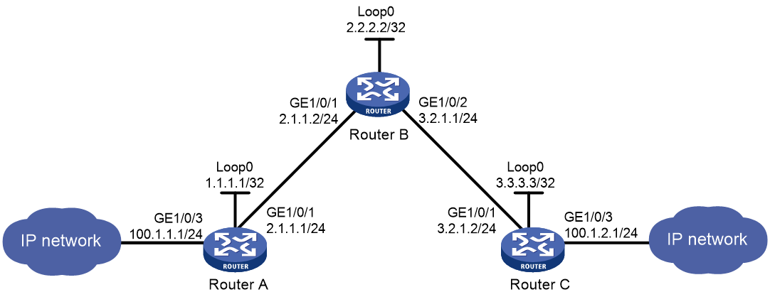
Procedure
1. Configure IP addresses and masks for interfaces. (Details not shown.)
2. Configure IS-IS to advertise interface addresses, including the loopback interface address:
# Configure Router A.
<RouterA> system-view
[RouterA] isis 1
[RouterA-isis-1] network-entity 00.0005.0000.0000.0001.00
[RouterA-isis-1] quit
[RouterA] interface gigabitethernet 1/0/1
[RouterA-GigabitEthernet1/0/1] isis enable 1
[RouterA-GigabitEthernet1/0/1] quit
[RouterA] interface loopback 0
[RouterA-LoopBack0] isis enable 1
[RouterA-LoopBack0] quit
# Configure Router B.
<RouterB> system-view
[RouterB] isis 1
[RouterB-isis-1] network-entity 00.0005.0000.0000.0002.00
[RouterB-isis-1] quit
[RouterB] interface gigabitethernet 1/0/1
[RouterB-GigabitEthernet1/0/1] isis enable 1
[RouterB-GigabitEthernet1/0/1] quit
[RouterB] interface gigabitethernet 1/0/2
[RouterB-GigabitEthernet1/0/2] isis enable 1
[RouterB-GigabitEthernet1/0/2] quit
[RouterB] interface loopback 0
[RouterB-LoopBack0] isis enable 1
[RouterB-LoopBack0] quit
# Configure Router C.
<RouterC> system-view
[RouterC] isis 1
[RouterC-isis-1] network-entity 00.0005.0000.0000.0003.00
[RouterC-isis-1] quit
[RouterC] interface gigabitethernet 1/0/1
[RouterC-GigabitEthernet1/0/1] isis enable 1
[RouterC-GigabitEthernet1/0/1] quit
[RouterC] interface loopback 0
[RouterC-LoopBack0] isis enable 1
[RouterC-LoopBack0] quit
# Execute the display ip routing-table command on each router to verify that the routers have learned the routes to one another, including the routes to the loopback interfaces. (Details not shown.)
3. Configure an LSR ID, and enable MPLS and MPLS TE:
# Configure Router A.
[RouterA] mpls lsr-id 1.1.1.1
[RouterA] mpls te
[RouterA-te] quit
[RouterA] interface gigabitethernet 1/0/1
[RouterA-GigabitEthernet1/0/1] mpls enable
[RouterA-GigabitEthernet1/0/1] mpls te enable
[RouterA-GigabitEthernet1/0/1] quit
# Configure Router B.
[RouterB] mpls lsr-id 2.2.2.2
[RouterB] mpls te
[RouterB-te] quit
[RouterB] interface gigabitethernet 1/0/1
[RouterB-GigabitEthernet1/0/1] mpls enable
[RouterB-GigabitEthernet1/0/1] mpls te enable
[RouterB-GigabitEthernet1/0/1] quit
[RouterB] interface gigabitethernet 1/0/2
[RouterB-GigabitEthernet1/0/2] mpls enable
[RouterB-GigabitEthernet1/0/2] mpls te enable
[RouterB-GigabitEthernet1/0/2] quit
# Configure Router C.
[RouterC] mpls lsr-id 3.3.3.3
[RouterC] mpls te
[RouterC-te] quit
[RouterC] interface gigabitethernet 1/0/1
[RouterC-GigabitEthernet1/0/1] mpls enable
[RouterC-GigabitEthernet1/0/1] mpls te enable
[RouterC-GigabitEthernet1/0/1] quit
4. Configure MPLS TE attributes of links:
# Set the maximum link bandwidth and maximum reservable bandwidth on Router A.
[RouterA] interface gigabitethernet 1/0/1
[RouterA-GigabitEthernet1/0/1] mpls te max-link-bandwidth 10000
[RouterA-GigabitEthernet1/0/1] mpls te max-reservable-bandwidth 5000
[RouterA-GigabitEthernet1/0/1] quit
# Set the maximum link bandwidth and maximum reservable bandwidth on Router B.
[RouterB] interface gigabitethernet 1/0/1
[RouterB-GigabitEthernet1/0/1] mpls te max-link-bandwidth 10000
[RouterB-GigabitEthernet1/0/1] mpls te max-reservable-bandwidth 5000
[RouterB-GigabitEthernet1/0/1] quit
[RouterB] interface gigabitethernet 1/0/2
[RouterB-GigabitEthernet1/0/2] mpls te max-link-bandwidth 10000
[RouterB-GigabitEthernet1/0/2] mpls te max-reservable-bandwidth 5000
[RouterB-GigabitEthernet1/0/2] quit
# Set the maximum link bandwidth and maximum reservable bandwidth on Router C.
[RouterC] interface gigabitethernet 1/0/1
[RouterC-GigabitEthernet1/0/1] mpls te max-link-bandwidth 10000
[RouterC-GigabitEthernet1/0/1] mpls te max-reservable-bandwidth 5000
[RouterC-GigabitEthernet1/0/1] quit
5. Configure an MPLS TE tunnel on Router A:
# Configure MPLS TE tunnel interface Tunnel 0.
[RouterA] interface tunnel 0 mode mpls-te
[RouterA-Tunnel0] ip address 6.1.1.1 255.255.255.0
# Specify the tunnel destination address as the LSR ID of Router C.
[RouterA-Tunnel0] destination 3.3.3.3
# Configure MPLS TE to use a static CRLSP to establish the tunnel.
[RouterA-Tunnel0] mpls te signaling static
[RouterA-Tunnel0] quit
6. Create a static CRLSP:
# Configure Router A as the ingress node of the static CRLSP, and specify the next hop address as 2.1.1.2, outgoing label as 20, and bandwidth for the tunnel as 2000 kbps.
[RouterA] static-cr-lsp ingress static-cr-lsp-1 nexthop 2.1.1.2 out-label 20 bandwidth 2000
# On Router A, configure Tunnel 0 to use static CRLSP static-cr-lsp-1.
[RouterA] interface tunnel0
[RouterA-Tunnel0] mpls te static-cr-lsp static-cr-lsp-1
[RouterA-Tunnel0] quit
# Configure Router B as the transit node of the static CRLSP, and specify the incoming label as 20, next hop address as 3.2.1.2, outgoing label as 30, and bandwidth for the tunnel as 2000 kbps.
[RouterB] static-cr-lsp transit static-cr-lsp-1 in-label 20 nexthop 3.2.1.2 out-label 30 bandwidth 2000
# Configure Router C as the egress node of the static CRLSP, and specify the incoming label as 30.
[RouterC] static-cr-lsp egress static-cr-lsp-1 in-label 30
7. Configure a static route on Router A to direct traffic destined for subnet 100.1.2.0/24 to MPLS TE tunnel 0.
[RouterA] ip route-static 100.1.2.0 24 tunnel 0 preference 1
Verifying the configuration
# Verify that the tunnel interface is up on Router A.
[RouterA] display interface tunnel
Tunnel0
Current state: UP
Line protocol state: UP
Description: Tunnel0 Interface
Bandwidth: 64kbps
Maximum transmission unit: 1496
Internet address: 6.1.1.1/24 (primary)
Tunnel source unknown, destination 3.3.3.3
Tunnel TTL 255
Tunnel protocol/transport CR_LSP
Output queue - Urgent queuing: Size/Length/Discards 0/100/0
Output queue - Protocol queuing: Size/Length/Discards 0/500/0
Output queue - FIFO queuing: Size/Length/Discards 0/75/0
Last clearing of counters: Never
Last 300 seconds input rate: 0 bytes/sec, 0 bits/sec, 0 packets/sec
Last 300 seconds output rate: 0 bytes/sec, 0 bits/sec, 0 packets/sec
Input: 0 packets, 0 bytes, 0 drops
Output: 0 packets, 0 bytes, 0 drops
# Display detailed information about the MPLS TE tunnel on Router A.
[RouterA] display mpls te tunnel-interface
Tunnel Name : Tunnel 0
Tunnel State : Up (Main CRLSP up)
Tunnel Attributes :
LSP ID : 1 Tunnel ID : 0
Admin State : Normal
Ingress LSR ID : 1.1.1.1 Egress LSR ID : 3.3.3.3
Signaling : Static Static CRLSP Name : static-cr-lsp-1
Static SRLSP Name : -
Resv Style : -
Tunnel mode : -
Reverse-LSP name : -
Reverse-LSP LSR ID : - Reverse-LSP Tunnel ID: -
Class Type : - Tunnel Bandwidth : -
Reserved Bandwidth : -
Setup Priority : 0 Holding Priority : 0
Affinity Attr/Mask : -/-
Explicit Path : -
Backup Explicit Path : -
Metric Type : TE
Record Route : - Record Label : -
FRR Flag : - Bandwidth Protection : -
Backup Bandwidth Flag: - Backup Bandwidth Type: -
Backup Bandwidth : -
Bypass Tunnel : - Auto Created : -
Route Pinning : -
Retry Limit : 3 Retry Interval : 2 sec
Reoptimization : - Reoptimization Freq : -
Backup Type : - Backup LSP ID : -
Auto Bandwidth : - Auto Bandwidth Freq : -
Min Bandwidth : - Max Bandwidth : -
Collected Bandwidth : - Service-Class : -
# Display static CRLSP information on each router.
[RouterA] display mpls lsp
FEC Proto In/Out Label Interface/Out NHLFE
1.1.1.1/0/1 StaticCR -/20 GE1/0/1
2.1.1.2 Local -/- GE1/0/1
Tunnel0 Local -/- NHLFE1025
[RouterB] display mpls lsp
FEC Proto In/Out Label Interface/Out NHLFE
- StaticCR 20/30 GE1/0/2
3.2.1.2 Local -/- GE1/0/2
[RouterC] display mpls lsp
FEC Proto In/Out Label Interface/Out NHLFE
- StaticCR 30/- -
[RouterA] display mpls static-cr-lsp
Name LSR Type In/Out Label Out Interface State
static-cr-lsp-1 Ingress Null/20 GE1/0/1 Up
[RouterB] display mpls static-cr-lsp
Name LSR Type In/Out Label Out Interface State
static-cr-lsp-1 Transit 20/30 GE1/0/2 Up
[RouterC] display mpls static-cr-lsp
Name LSR Type In/Out Label Out Interface State
static-cr-lsp-1 Egress 30/Null - Up
# Execute the display ip routing-table command on Router A. The output shows a static route entry with interface Tunnel 0 as the output interface. (Details not shown.)
Example: Establishing an MPLS TE tunnel with RSVP-TE
Network configuration
Router A, Router B, Router C, and Router D run IS-IS and all of them are Level-2 routers.
Use RSVP-TE to establish an MPLS TE tunnel from Router A to Router D to transmit data between the two IP networks. The MPLS TE tunnel requires a bandwidth of 2000 kbps.
The maximum bandwidth of the link that the tunnel traverses is 10000 kbps and the maximum reservable bandwidth of the link is 5000 kbps.
Figure 10 Network diagram
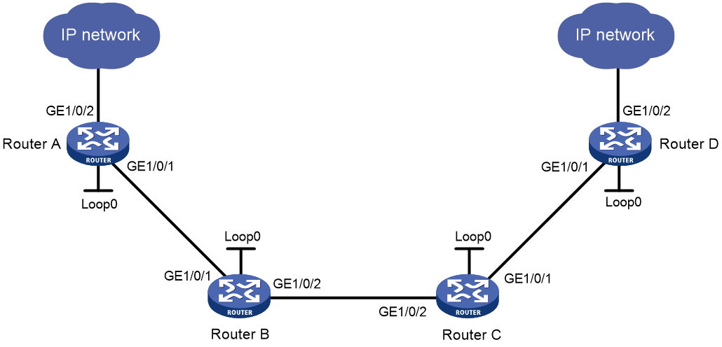
Table 2 Interface and IP address assignment
|
Interface |
IP address |
Device |
Interface |
IP address |
|
|
Router A |
Loop0 |
1.1.1.9/32 |
Router C |
Loop0 |
3.3.3.9/32 |
|
|
GE1/0/1 |
10.1.1.1/24 |
|
GE1/0/1 |
30.1.1.1/24 |
|
|
GE1/0/2 |
100.1.1.1/24 |
|
GE1/0/2 |
20.1.1.2/24 |
|
Router B |
Loop0 |
2.2.2.9/32 |
Router D |
Loop0 |
4.4.4.9/32 |
|
|
GE1/0/1 |
10.1.1.2/24 |
|
GE1/0/1 |
30.1.1.2/24 |
|
|
GE1/0/2 |
20.1.1.1/24 |
|
GE1/0/2 |
100.1.2.1/24 |
Procedure
1. Configure IP addresses and masks for interfaces. (Details not shown.)
2. Configure IS-IS to advertise interface addresses, including the loopback interface address:
# Configure Router A.
<RouterA> system-view
[RouterA] isis 1
[RouterA-isis-1] network-entity 00.0005.0000.0000.0001.00
[RouterA-isis-1] quit
[RouterA] interface gigabitethernet 1/0/1
[RouterA-GigabitEthernet1/0/1] isis enable 1
[RouterA-GigabitEthernet1/0/1] isis circuit-level level-2
[RouterA-GigabitEthernet1/0/1] quit
[RouterA] interface loopback 0
[RouterA-LoopBack0] isis enable 1
[RouterA-LoopBack0] isis circuit-level level-2
[RouterA-LoopBack0] quit
# Configure Router B.
<RouterB> system-view
[RouterB] isis 1
[RouterB-isis-1] network-entity 00.0005.0000.0000.0002.00
[RouterB-isis-1] quit
[RouterB] interface gigabitethernet 1/0/1
[RouterB-GigabitEthernet1/0/1] isis enable 1
[RouterB-GigabitEthernet1/0/1] isis circuit-level level-2
[RouterB-GigabitEthernet1/0/1] quit
[RouterB] interface gigabitethernet 1/0/2
[RouterB-GigabitEthernet1/0/2] isis enable 1
[RouterB-GigabitEthernet1/0/2] isis circuit-level level-2
[RouterB-GigabitEthernet1/0/2] quit
[RouterB] interface loopback 0
[RouterB-LoopBack0] isis enable 1
[RouterB-LoopBack0] isis circuit-level level-2
[RouterB-LoopBack0] quit
# Configure Router C.
<RouterC> system-view
[RouterC] isis 1
[RouterC-isis-1] network-entity 00.0005.0000.0000.0003.00
[RouterC-isis-1] quit
[RouterC] interface gigabitethernet 1/0/1
[RouterC-GigabitEthernet1/0/1] isis enable 1
[RouterC-GigabitEthernet1/0/1] isis circuit-level level-2
[RouterC-GigabitEthernet1/0/1] quit
[RouterC] interface gigabitethernet 1/0/2
[RouterC-GigabitEthernet1/0/2] isis enable 1
[RouterC-GigabitEthernet1/0/2] isis circuit-level level-2
[RouterC-GigabitEthernet1/0/2] quit
[RouterC] interface loopback 0
[RouterC-LoopBack0] isis enable 1
[RouterC-LoopBack0] isis circuit-level level-2
[RouterC-LoopBack0] quit
# Configure Router D.
<RouterD> system-view
[RouterD] isis 1
[RouterD-isis-1] network-entity 00.0005.0000.0000.0004.00
[RouterD-isis-1] quit
[RouterD] interface gigabitethernet 1/0/1
[RouterD-GigabitEthernet1/0/1] isis enable 1
[RouterD-GigabitEthernet1/0/1] isis circuit-level level-2
[RouterD-GigabitEthernet1/0/1] quit
[RouterD] interface loopback 0
[RouterD-LoopBack0] isis enable 1
[RouterD-LoopBack0] isis circuit-level level-2
[RouterD-LoopBack0] quit
# Execute the display ip routing-table command on each router to verify that the routers have learned the routes to one another, including the routes to the loopback interfaces. (Details not shown.)
3. Configure an LSR ID, and enable MPLS, MPLS TE, and RSVP-TE:
# Configure Router A.
[RouterA] mpls lsr-id 1.1.1.9
[RouterA] mpls te
[RouterA-te] quit
[RouterA] rsvp
[RouterA-rsvp] quit
[RouterA] interface gigabitethernet 1/0/1
[RouterA-GigabitEthernet1/0/1] mpls enable
[RouterA-GigabitEthernet1/0/1] mpls te enable
[RouterA-GigabitEthernet1/0/1] rsvp enable
[RouterA-GigabitEthernet1/0/1] quit
# Configure Router B.
[RouterB] mpls lsr-id 2.2.2.9
[RouterB] mpls te
[RouterB-te] quit
[RouterB] rsvp
[RouterB-rsvp] quit
[RouterB] interface gigabitethernet 1/0/1
[RouterB-GigabitEthernet1/0/1] mpls enable
[RouterB-GigabitEthernet1/0/1] mpls te enable
[RouterB-GigabitEthernet1/0/1] rsvp enable
[RouterB-GigabitEthernet1/0/1] quit
[RouterB] interface gigabitethernet 1/0/2
[RouterB-GigabitEthernet1/0/2] mpls enable
[RouterB-GigabitEthernet1/0/2] mpls te enable
[RouterB-GigabitEthernet1/0/2] rsvp enable
[RouterB-GigabitEthernet1/0/2] quit
# Configure Router C.
[RouterC] mpls lsr-id 3.3.3.9
[RouterC] mpls te
[RouterC-te] quit
[RouterC] rsvp
[RouterC-rsvp] quit
[RouterC] interface gigabitethernet 1/0/1
[RouterC-GigabitEthernet1/0/1] mpls enable
[RouterC-GigabitEthernet1/0/1] mpls te enable
[RouterC-GigabitEthernet1/0/1] rsvp enable
[RouterC-GigabitEthernet1/0/1] quit
[RouterC] interface gigabitethernet 1/0/2
[RouterC-GigabitEthernet1/0/2] mpls enable
[RouterC-GigabitEthernet1/0/2] mpls te enable
[RouterC-GigabitEthernet1/0/2] rsvp enable
[RouterC-GigabitEthernet1/0/2] quit
# Configure Router D.
[RouterD] mpls lsr-id 4.4.4.9
[RouterD] mpls te
[RouterD-te] quit
[RouterD] rsvp
[RouterD-rsvp] quit
[RouterD] interface gigabitethernet 1/0/1
[RouterD-GigabitEthernet1/0/1] mpls enable
[RouterD-GigabitEthernet1/0/1] mpls te enable
[RouterD-GigabitEthernet1/0/1] rsvp enable
[RouterD-GigabitEthernet1/0/1] quit
4. Configure IS-IS TE:
# Configure Router A.
[RouterA] isis 1
[RouterA-isis-1] cost-style wide
[RouterA-isis-1] mpls te enable level-2
[RouterA-isis-1] quit
# Configure Router B.
[RouterB] isis 1
[RouterB-isis-1] cost-style wide
[RouterB-isis-1] mpls te enable level-2
[RouterB-isis-1] quit
# Configure Router C.
[RouterC] isis 1
[RouterC-isis-1] cost-style wide
[RouterC-isis-1] mpls te enable level-2
[RouterC-isis-1] quit
# Configure Router D.
[RouterD] isis 1
[RouterD-isis-1] cost-style wide
[RouterD-isis-1] mpls te enable level-2
[RouterD-isis-1] quit
5. Configure MPLS TE attributes of links:
# Set the maximum link bandwidth and maximum reservable bandwidth on Router A.
[RouterA] interface gigabitethernet 1/0/1
[RouterA-GigabitEthernet1/0/1] mpls te max-link-bandwidth 10000
[RouterA-GigabitEthernet1/0/1] mpls te max-reservable-bandwidth 5000
[RouterA-GigabitEthernet1/0/1] quit
# Set the maximum link bandwidth and maximum reservable bandwidth on Router B.
[RouterB] interface gigabitethernet 1/0/1
[RouterB-GigabitEthernet1/0/1] mpls te max-link-bandwidth 10000
[RouterB-GigabitEthernet1/0/1] mpls te max-reservable-bandwidth 5000
[RouterB-GigabitEthernet1/0/1] quit
[RouterB] interface gigabitethernet 1/0/2
[RouterB-GigabitEthernet1/0/2] mpls te max-link-bandwidth 10000
[RouterB-GigabitEthernet1/0/2] mpls te max-reservable-bandwidth 5000
[RouterB-GigabitEthernet1/0/2] quit
# Set the maximum link bandwidth and maximum reservable bandwidth on Router C.
[RouterC] interface gigabitethernet 1/0/1
[RouterC-GigabitEthernet1/0/1] mpls te max-link-bandwidth 10000
[RouterC-GigabitEthernet1/0/1] mpls te max-reservable-bandwidth 5000
[RouterC-GigabitEthernet1/0/1] quit
[RouterC] interface gigabitethernet 1/0/2
[RouterC-GigabitEthernet1/0/2] mpls te max-link-bandwidth 10000
[RouterC-GigabitEthernet1/0/2] mpls te max-reservable-bandwidth 5000
[RouterC-GigabitEthernet1/0/2] quit
# Set the maximum link bandwidth and maximum reservable bandwidth on Router D.
[RouterD] interface gigabitethernet 1/0/1
[RouterD-GigabitEthernet1/0/1] mpls te max-link-bandwidth 10000
[RouterD-GigabitEthernet1/0/1] mpls te max-reservable-bandwidth 5000
[RouterD-GigabitEthernet1/0/1] quit
6. Configure an MPLS TE tunnel on Router A:
# Configure MPLS TE tunnel interface Tunnel 1.
[RouterA] interface tunnel 1 mode mpls-te
[RouterA-Tunnel1] ip address 7.1.1.1 255.255.255.0
# Specify the tunnel destination address as the LSR ID of Router D.
[RouterA-Tunnel1] destination 4.4.4.9
# Configure MPLS TE to use RSVP-TE to establish the tunnel.
[RouterA-Tunnel1] mpls te signaling rsvp-te
# Assign 2000 kbps bandwidth to the tunnel.
[RouterA-Tunnel1] mpls te bandwidth 2000
[RouterA-Tunnel1] quit
7. Configure a static route on Router A to direct the traffic destined for subnet 100.1.2.0/24 to MPLS TE tunnel 1.
[RouterA] ip route-static 100.1.2.0 24 tunnel 1 preference 1
Verifying the configuration
# Verify that the tunnel interface is up on Router A.
[RouterA] display interface tunnel
Tunnel1
Current state: UP
Line protocol state: UP
Description: Tunnel1 Interface
Bandwidth: 64kbps
Maximum transmission unit: 1496
Internet address: 7.1.1.1/24 (primary)
Tunnel source unknown, destination 4.4.4.9
Tunnel TTL 255
Tunnel protocol/transport CR_LSP
Output queue - Urgent queuing: Size/Length/Discards 0/1024/0
Output queue - Protocol queuing: Size/Length/Discards 0/500/0
Output queue - FIFO queuing: Size/Length/Discards 0/75/0
Last clearing of counters: Never
Last 300 seconds input: 0 bytes/sec, 0 bits/sec, 0 packets/sec
Last 300 seconds output: 0 bytes/sec, 0 bits/sec, 0 packets/sec
Input: 0 packets, 0 bytes, 0 drops
Output: 0 packets, 0 bytes, 0 drops
# Display detailed information about the MPLS TE tunnel on Router A.
[RouterA] display mpls te tunnel-interface
Tunnel Name : Tunnel 1
Tunnel State : Up (Main CRLSP up, Shared-resource CRLSP down)
Tunnel Attributes :
LSP ID : 23331 Tunnel ID : 1
Admin State : Normal
Ingress LSR ID : 1.1.1.9 Egress LSR ID : 4.4.4.9
Signaling : RSVP-TE Static CRLSP Name : -
Static SRLSP Name : -
Resv Style : SE
Tunnel mode : -
Reverse-LSP name : -
Reverse-LSP LSR ID : - Reverse-LSP Tunnel ID: -
Class Type : CT0 Tunnel Bandwidth : 2000 kbps
Reserved Bandwidth : 2000 kbps
Setup Priority : 7 Holding Priority : 7
Affinity Attr/Mask : 0/0
Explicit Path : -
Backup Explicit Path : -
Metric Type : TE
Record Route : Disabled Record Label : Disabled
FRR Flag : Disabled Bandwidth Protection : Disabled
Backup Bandwidth Flag: Disabled Backup Bandwidth Type: -
Backup Bandwidth : -
Bypass Tunnel : No Auto Created : No
Route Pinning : Disabled
Retry Limit : 10 Retry Interval : 2 sec
Reoptimization : Disabled Reoptimization Freq : -
Backup Type : None Backup LSP ID : -
Auto Bandwidth : Disabled Auto Bandwidth Freq : -
Min Bandwidth : - Max Bandwidth : -
Collected Bandwidth : - Service-Class : -
# Execute the display ip routing-table command on Router A. The output shows a static route entry with interface Tunnel 1 as the output interface. (Details not shown.)
Example: Establishing an inter-AS MPLS TE tunnel with RSVP-TE
Network configuration
Router A and Router B are in AS 100. Router C and Router D are in AS 200. AS 100 and AS 200 use OSPF as the IGP.
Establish an EBGP connection between ASBRs Router B and Router C. Redistribute BGP routes into OSPF and OSPF routes into BGP, so that AS 100 and AS 200 can reach each other.
Use RSVP-TE to establish an MPLS TE tunnel from Router A to Router D to transmit data between the two IP networks. The tunnel requires a bandwidth of 2000 kbps. The maximum bandwidth of the link that the tunnel traverses is 10000 kbps, and the maximum reservable bandwidth of the link is 5000 kbps.
Figure 11 Network diagram
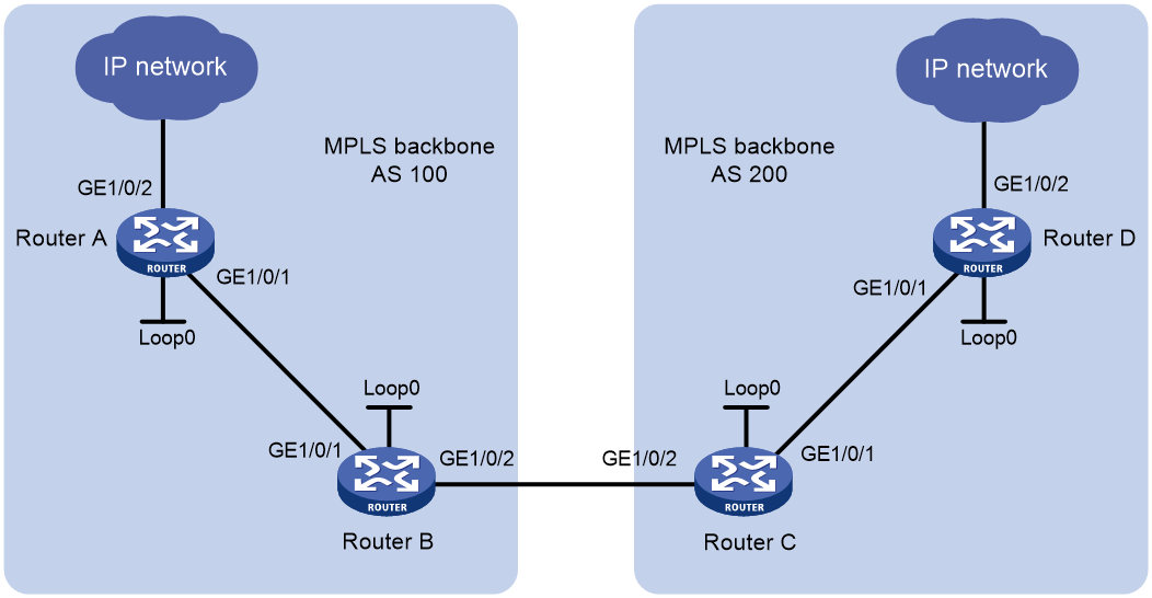
Table 3 Interface and IP address assignment
|
Device |
Interface |
IP address |
Device |
Interface |
IP address |
|
Router A |
Loop0 |
1.1.1.9/32 |
Router C |
Loop0 |
3.3.3.9/32 |
|
|
GE1/0/1 |
10.1.1.1/24 |
|
GE1/0/1 |
30.1.1.1/24 |
|
|
GE1/0/2 |
100.1.1.0/24 |
|
GE1/0/2 |
20.1.1.2/24 |
|
Router B |
Loop0 |
2.2.2.9/32 |
Router D |
Loop0 |
4.4.4.9/32 |
|
|
GE1/0/1 |
10.1.1.2/24 |
|
GE1/0/1 |
30.1.1.2/24 |
|
|
GE1/0/2 |
20.1.1.1/24 |
|
GE1/0/2 |
100.1.2.0/24 |
Procedure
1. Configure IP addresses and masks for interfaces. (Details not shown.)
2. Configure OSPF to advertise routes within the ASs, and redistribute the direct and BGP routes into OSPF on Router B and Router C:
# Configure Router A.
<RouterA> system-view
[RouterA] ospf
[RouterA-ospf-1] area 0
[RouterA-ospf-1-area-0.0.0.0] network 10.1.1.0 0.0.0.255
[RouterA-ospf-1-area-0.0.0.0] network 1.1.1.9 0.0.0.0
[RouterA-ospf-1-area-0.0.0.0] quit
[RouterA-ospf-1] quit
# Configure Router B.
<RouterB> system-view
[RouterB] ospf
[RouterB-ospf-1] import-route direct
[RouterB-ospf-1] import-route bgp
[RouterB-ospf-1] area 0
[RouterB-ospf-1-area-0.0.0.0] network 10.1.1.0 0.0.0.255
[RouterB-ospf-1-area-0.0.0.0] network 2.2.2.9 0.0.0.0
[RouterB-ospf-1-area-0.0.0.0] quit
[RouterB-ospf-1] quit
# Configure Router C.
<RouterC> system-view
[RouterC] ospf
[RouterC-ospf-1] import-route direct
[RouterC-ospf-1] import-route bgp
[RouterC-ospf-1] area 0
[RouterC-ospf-1-area-0.0.0.0] network 30.1.1.0 0.0.0.255
[RouterC-ospf-1-area-0.0.0.0] network 3.3.3.9 0.0.0.0
[RouterC-ospf-1-area-0.0.0.0] quit
[RouterC-ospf-1] quit
# Configure Router D.
<RouterD> system-view
[RouterD] ospf
[RouterD-ospf-1] area 0
[RouterD-ospf-1-area-0.0.0.0] network 30.1.1.0 0.0.0.255
[RouterD-ospf-1-area-0.0.0.0] network 4.4.4.9 0.0.0.0
[RouterD-ospf-1-area-0.0.0.0] quit
[RouterD-ospf-1] quit
# Verify that the routers have learned the routes to one another, including the routes to the loopback interfaces. This example uses Router A.
[RouterA] display ip routing-table
Destinations : 6 Routes : 6
Destination/Mask Proto Pre Cost NextHop Interface
1.1.1.9/32 Direct 0 0 127.0.0.1 InLoop0
2.2.2.9/32 O_INTRA 10 1 10.1.1.2 GE1/0/1
10.1.1.0/24 Direct 0 0 10.1.1.1 GE1/0/1
10.1.1.1/32 Direct 0 0 127.0.0.1 InLoop0
127.0.0.0/8 Direct 0 0 127.0.0.1 InLoop0
127.0.0.1/32 Direct 0 0 127.0.0.1 InLoop0
3. Configure BGP on Router B and Router C to ensure that the ASs can communicate with each other:
# Configure Router B.
[RouterB] bgp 100
[RouterB-bgp] peer 20.1.1.2 as-number 200
[RouterB-bgp] address-family ipv4 unicast
[RouterB-bgp-ipv4] peer 20.1.1.2 enable
[RouterB-bgp-ipv4] import-route ospf
[RouterB-bgp-ipv4] import-route direct
[RouterB-bgp-ipv4] quit
[RouterB-bgp] quit
# Configure Router C.
[RouterC] bgp 200
[RouterC-bgp] peer 20.1.1.1 as-number 100
[RouterC-bgp] address-family ipv4 unicast
[RouterC-bgp-ipv4] peer 20.1.1.1 enable
[RouterC-bgp-ipv4] import-route ospf
[RouterC-bgp-ipv4] import-route direct
[RouterC-bgp-ipv4] quit
[RouterC-bgp] quit
# Verify that the routers have learned the AS-external routes. This example uses Router A.
[RouterA] display ip routing-table
Destinations : 10 Routes : 10
Destination/Mask Proto Pre Cost NextHop Interface
1.1.1.9/32 Direct 0 0 127.0.0.1 InLoop0
2.2.2.9/32 O_INTRA 10 1 10.1.1.2 GE1/0/1
3.3.3.9/32 O_ASE 150 1 10.1.1.2 GE1/0/1
4.4.4.9/32 O_ASE 150 1 10.1.1.2 GE1/0/1
10.1.1.0/24 Direct 0 0 10.1.1.1 GE1/0/1
10.1.1.1/32 Direct 0 0 127.0.0.1 InLoop0
20.1.1.0/24 O_ASE 150 1 10.1.1.2 GE1/0/1
30.1.1.0/24 O_ASE 150 1 10.1.1.2 GE1/0/1
127.0.0.0/8 Direct 0 0 127.0.0.1 InLoop0
127.0.0.1/32 Direct 0 0 127.0.0.1 InLoop0
4. Configure an LSR ID, and enable MPLS, MPLS TE, and RSVP-TE:
# Configure Router A.
[RouterA] mpls lsr-id 1.1.1.9
[RouterA] mpls te
[RouterA-te] quit
[RouterA] rsvp
[RouterA-rsvp] quit
[RouterA] interface gigabitethernet 1/0/1
[RouterA-GigabitEthernet1/0/1] mpls enable
[RouterA-GigabitEthernet1/0/1] mpls te enable
[RouterA-GigabitEthernet1/0/1] rsvp enable
[RouterA-GigabitEthernet1/0/1] quit
# Configure Router B.
[RouterB] mpls lsr-id 2.2.2.9
[RouterB] mpls te
[RouterB-te] quit
[RouterB] rsvp
[RouterB-rsvp] quit
[RouterB] interface gigabitethernet 1/0/1
[RouterB-GigabitEthernet1/0/1] mpls enable
[RouterB-GigabitEthernet1/0/1] mpls te enable
[RouterB-GigabitEthernet1/0/1] rsvp enable
[RouterB-GigabitEthernet1/0/1] quit
[RouterB] interface gigabitethernet 1/0/2
[RouterB-GigabitEthernet1/0/2] mpls enable
[RouterB-GigabitEthernet1/0/2] mpls te enable
[RouterB-GigabitEthernet1/0/2] rsvp enable
[RouterB-GigabitEthernet1/0/2] quit
# Configure Router C.
[RouterC] mpls lsr-id 3.3.3.9
[RouterC] mpls te
[RouterC-te] quit
[RouterC] rsvp
[RouterC-rsvp] quit
[RouterC] interface gigabitethernet 1/0/1
[RouterC-GigabitEthernet1/0/1] mpls enable
[RouterC-GigabitEthernet1/0/1] mpls te enable
[RouterC-GigabitEthernet1/0/1] rsvp enable
[RouterC-GigabitEthernet1/0/1] quit
[RouterC] interface gigabitethernet 1/0/2
[RouterC-GigabitEthernet1/0/2] mpls enable
[RouterC-GigabitEthernet1/0/2] mpls te enable
[RouterC-GigabitEthernet1/0/2] rsvp enable
[RouterC-GigabitEthernet1/0/2] quit
# Configure Router D.
[RouterD] mpls lsr-id 4.4.4.9
[RouterD] mpls te
[RouterD-te] quit
[RouterD] rsvp
[RouterD-rsvp] quit
[RouterD] interface gigabitethernet 1/0/1
[RouterD-GigabitEthernet1/0/1] mpls enable
[RouterD-GigabitEthernet1/0/1] mpls te enable
[RouterD-GigabitEthernet1/0/1] rsvp enable
[RouterD-GigabitEthernet1/0/1] quit
5. Configure OSPF TE:
# Configure Router A.
[RouterA] ospf
[RouterA-ospf-1] opaque-capability enable
[RouterA-ospf-1] area 0
[RouterA-ospf-1-area-0.0.0.0] mpls te enable
[RouterA-ospf-1-area-0.0.0.0] quit
[RouterA-ospf-1] quit
# Configure Router B.
[RouterB] ospf
[RouterB-ospf-1] opaque-capability enable
[RouterB-ospf-1] area 0
[RouterB-ospf-1-area-0.0.0.0] mpls te enable
[RouterB-ospf-1-area-0.0.0.0] quit
[RouterB-ospf-1] quit
# Configure Router C.
[RouterC] ospf
[RouterC-ospf-1] opaque-capability enable
[RouterC-ospf-1] area 0
[RouterC-ospf-1-area-0.0.0.0] mpls te enable
[RouterC-ospf-1-area-0.0.0.0] quit
[RouterC-ospf-1] quit
# Configure Router D.
[RouterD] ospf
[RouterD-ospf-1] opaque-capability enable
[RouterD-ospf-1] area 0
[RouterD-ospf-1-area-0.0.0.0] mpls te enable
[RouterD-ospf-1-area-0.0.0.0] quit
[RouterD-ospf-1] quit
6. Configure an explicit path on Router A. Specify Router B and Router D as loose nodes, and Router C as a strict node.
[RouterA] explicit-path atod
[RouterA-explicit-path-atod] nexthop 10.1.1.2 include loose
[RouterA-explicit-path-atod] nexthop 20.1.1.2 include strict
[RouterA-explicit-path-atod] nexthop 30.1.1.2 include loose
[RouterA-explicit-path-atod] quit
7. Configure MPLS TE attributes of links:
# Set the maximum link bandwidth and maximum reservable bandwidth on Router A.
[RouterA] interface gigabitethernet 1/0/1
[RouterA-GigabitEthernet1/0/1] mpls te max-link-bandwidth 10000
[RouterA-GigabitEthernet1/0/1] mpls te max-reservable-bandwidth 5000
[RouterA-GigabitEthernet1/0/1] quit
# Set the maximum link bandwidth and maximum reservable bandwidth on Router B.
[RouterB] interface gigabitethernet 1/0/1
[RouterB-GigabitEthernet1/0/1] mpls te max-link-bandwidth 10000
[RouterB-GigabitEthernet1/0/1] mpls te max-reservable-bandwidth 5000
[RouterB-GigabitEthernet1/0/1] quit
[RouterB] interface gigabitethernet 1/0/2
[RouterB-GigabitEthernet1/0/2] mpls te max-link-bandwidth 10000
[RouterB-GigabitEthernet1/0/2] mpls te max-reservable-bandwidth 5000
[RouterB-GigabitEthernet1/0/2] quit
# Set the maximum link bandwidth and maximum reservable bandwidth on Router C.
[RouterC] interface gigabitethernet 1/0/1
[RouterC-GigabitEthernet1/0/1] mpls te max-link-bandwidth 10000
[RouterC-GigabitEthernet1/0/1] mpls te max-reservable-bandwidth 5000
[RouterC-GigabitEthernet1/0/1] quit
[RouterC] interface gigabitethernet 1/0/2
[RouterC-GigabitEthernet1/0/2] mpls te max-link-bandwidth 10000
[RouterC-GigabitEthernet1/0/2] mpls te max-reservable-bandwidth 5000
[RouterC-GigabitEthernet1/0/2] quit
# Set the maximum link bandwidth and maximum reservable bandwidth on Router D.
[RouterD] interface gigabitethernet 1/0/1
[RouterD-GigabitEthernet1/0/1] mpls te max-link-bandwidth 10000
[RouterD-GigabitEthernet1/0/1] mpls te max-reservable-bandwidth 5000
[RouterD-GigabitEthernet1/0/1] quit
8. Configure an MPLS TE tunnel on Router A:
# Configure MPLS TE tunnel interface Tunnel 1.
[RouterA] interface tunnel 1 mode mpls-te
[RouterA-Tunnel1] ip address 7.1.1.1 255.255.255.0
# Specify the tunnel destination address as the LSR ID of Router D.
[RouterA-Tunnel1] destination 4.4.4.9
# Configure MPLS TE to use RSVP-TE to establish the tunnel.
[RouterA-Tunnel1] mpls te signaling rsvp-te
# Assign 2000 kbps bandwidth to the tunnel.
[RouterA-Tunnel1] mpls te bandwidth 2000
# Specify explicit path atod for the tunnel.
[RouterA-Tunnel1] mpls te path preference 5 explicit-path atod
[RouterA-Tunnel1] quit
9. Configure a static route on Router A to direct the traffic destined for subnet 100.1.2.0/24 to MPLS TE tunnel 1.
[RouterA] ip route-static 100.1.2.0 24 tunnel 1 preference 1
Verifying the configuration
# Verify that the tunnel interface is up on Router A.
[RouterA] display interface tunnel 1
Tunnel1
Current state: UP
Line protocol state: UP
Description: Tunnel1 Interface
Bandwidth: 64kbps
Maximum transmission unit: 1496
Internet address: 7.1.1.1/24 (primary)
Tunnel source unknown, destination 4.4.4.9
Tunnel TTL 255
Tunnel protocol/transport CR_LSP
Output queue - Urgent queuing: Size/Length/Discards 0/1024/0
Output queue - Protocol queuing: Size/Length/Discards 0/500/0
Output queue - FIFO queuing: Size/Length/Discards 0/75/0
Last clearing of counters: Never
Last 300 seconds input: 0 bytes/sec, 0 bits/sec, 0 packets/sec
Last 300 seconds output: 0 bytes/sec, 0 bits/sec, 0 packets/sec
Input: 0 packets, 0 bytes, 0 drops
Output: 0 packets, 0 bytes, 0 drops
# Display detailed information about the MPLS TE tunnel on Router A.
[RouterA] display mpls te tunnel-interface
Tunnel Name : Tunnel 1
Tunnel State : Up (Main CRLSP up, Shared-resource CRLSP down)
Tunnel Attributes :
LSP ID : 23549 Tunnel ID : 1
Admin State : Normal
Ingress LSR ID : 1.1.1.9 Egress LSR ID : 4.4.4.9
Signaling : RSVP-TE Static CRLSP Name : -
Static SRLSP Name : -
Resv Style : SE
Tunnel mode : -
Reverse-LSP name : -
Reverse-LSP LSR ID : - Reverse-LSP Tunnel ID: -
Class Type : CT0 Tunnel Bandwidth : 2000 kbps
Reserved Bandwidth : 2000 kbps
Setup Priority : 7 Holding Priority : 7
Affinity Attr/Mask : 0/0
Explicit Path : atod
Backup Explicit Path : -
Metric Type : TE
Record Route : Disabled Record Label : Disabled
FRR Flag : Disabled Bandwidth Protection : Disabled
Backup Bandwidth Flag: Disabled Backup Bandwidth Type: -
Backup Bandwidth : -
Bypass Tunnel : No Auto Created : No
Route Pinning : Disabled
Retry Limit : 10 Retry Interval : 2 sec
Reoptimization : Disabled Reoptimization Freq : -
Backup Type : None Backup LSP ID : -
Auto Bandwidth : Disabled Auto Bandwidth Freq : -
Min Bandwidth : - Max Bandwidth : -
Collected Bandwidth : - Service-Class : -
# Verify that Router A has a static route entry with interface Tunnel 1 as the output interface.
[RouterA] display ip routing-table
Destinations : 14 Routes : 14
Destination/Mask Proto Pre Cost NextHop Interface
1.1.1.9/32 Direct 0 0 127.0.0.1 InLoop0
2.2.2.9/32 O_INTRA 10 1 10.1.1.2 GE1/0/1
3.3.3.9/32 O_ASE 150 1 10.1.1.2 GE1/0/1
4.4.4.9/32 O_ASE 150 1 10.1.1.2 GE1/0/1
7.1.1.0/24 Direct 0 0 7.1.1.1 Tun1
7.1.1.1/32 Direct 0 0 127.0.0.1 InLoop0
10.1.1.0/24 Direct 0 0 10.1.1.1 GE1/0/1
10.1.1.1/32 Direct 0 0 127.0.0.1 InLoop0
20.1.1.0/24 O_ASE 150 1 10.1.1.2 GE1/0/1
100.1.2.0/24 Static 1 0 0.0.0.0 Tun1
127.0.0.0/8 Direct 0 0 127.0.0.1 InLoop0
127.0.0.1/32 Direct 0 0 127.0.0.1 InLoop0
Example: Establishing an inter-area MPLS TE tunnel over a CRLSP calculated by PCEs
Network configuration
Router A, Router B, Router C, and Router D support MPLS TE and run OSPF.
Configure Router A and Router B as PCEs, and configure Router C as a PCC to automatically discover the PCEs.
Establish an MPLS TE tunnel over a CRLSP from Router C to Router D that uses the inter-area path calculated by PCEs.
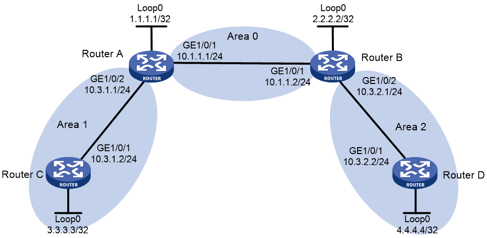
Procedure
1. Configure IP addresses and masks for interfaces. (Details not shown.)
2. Configure OSPF to advertise interface addresses and configure OSPF TE:
# Configure Router A.
<RouterA> system-view
[RouterA] ospf
[RouterA-ospf-1] area 0
[RouterA-ospf-1-area-0.0.0.0] network 10.1.1.0 0.0.0.255
[RouterA-ospf-1-area-0.0.0.0] network 1.1.1.1 0.0.0.0
[RouterA-ospf-1-area-0.0.0.0] mpls te enable
[RouterA-ospf-1-area-0.0.0.0] quit
[RouterA-ospf-1] area 1
[RouterA-ospf-1-area-0.0.0.1] network 10.3.1.0 0.0.0.255
[RouterA-ospf-1-area-0.0.0.1] mpls te enable
[RouterA-ospf-1-area-0.0.0.1] quit
[RouterA-ospf-1] quit
# Configure Router B.
<RouterB> system-view
[RouterB] ospf
[RouterB-ospf-1] area 0
[RouterB-ospf-1-area-0.0.0.0] network 10.1.1.0 0.0.0.255
[RouterB-ospf-1-area-0.0.0.0] network 2.2.2.2 0.0.0.0
[RouterB-ospf-1-area-0.0.0.0] mpls te enable
[RouterB-ospf-1-area-0.0.0.0] quit
[RouterB-ospf-1] area 2
[RouterB-ospf-1-area-0.0.0.2] network 10.3.2.0 0.0.0.255
[RouterB-ospf-1-area-0.0.0.2] mpls te enable
[RouterB-ospf-1-area-0.0.0.2] quit
[RouterB-ospf-1] quit
# Configure Router C.
<RouterC> system-view
[RouterC] ospf
[RouterC-ospf-1] area 1
[RouterC-ospf-1-area-0.0.0.1] network 10.3.1.0 0.0.0.255
[RouterC-ospf-1-area-0.0.0.1] network 3.3.3.3 0.0.0.0
[RouterC-ospf-1-area-0.0.0.1] mpls te enable
[RouterC-ospf-1-area-0.0.0.1] quit
[RouterC-ospf-1] quit
# Configure Router D.
<RouterD> system-view
[RouterD] ospf
[RouterD-ospf-1] area 2
[RouterD-ospf-1-area-0.0.0.2] network 10.3.2.0 0.0.0.255
[RouterD-ospf-1-area-0.0.0.2] network 4.4.4.4 0.0.0.0
[RouterD-ospf-1-area-0.0.0.2] mpls te enable
[RouterD-ospf-1-area-0.0.0.2] quit
[RouterD-ospf-1] quit
3. Configure an LSR ID, and enable MPLS, MPLS TE, and RSVP-TE:
# Configure Router A.
[RouterA] mpls lsr-id 1.1.1.1
[RouterA] mpls te
[RouterA-te] quit
[RouterA] rsvp
[RouterA-rsvp] quit
[RouterA] interface gigabitethernet 1/0/1
[RouterA-GigabitEthernet1/0/1] mpls enable
[RouterA-GigabitEthernet1/0/1] mpls te enable
[RouterA-GigabitEthernet1/0/1] rsvp enable
[RouterA-GigabitEthernet1/0/1] quit
[RouterA] interface gigabitethernet 1/0/2
[RouterA-GigabitEthernet1/0/2] mpls enable
[RouterA-GigabitEthernet1/0/2] mpls te enable
[RouterA-GigabitEthernet1/0/2] rsvp enable
[RouterA-GigabitEthernet1/0/2] quit
# Configure Router B.
[RouterB] mpls lsr-id 2.2.2.2
[RouterB] mpls te
[RouterB-te] quit
[RouterB] rsvp
[RouterB-rsvp] quit
[RouterB] interface gigabitethernet 1/0/1
[RouterB-GigabitEthernet1/0/1] mpls enable
[RouterB-GigabitEthernet1/0/1] mpls te enable
[RouterB-GigabitEthernet1/0/1] rsvp enable
[RouterB-GigabitEthernet1/0/1] quit
[RouterB] interface gigabitethernet 1/0/2
[RouterB-GigabitEthernet1/0/2] mpls enable
[RouterB-GigabitEthernet1/0/2] mpls te enable
[RouterB-GigabitEthernet1/0/2] rsvp enable
[RouterB-GigabitEthernet1/0/2] quit
# Configure Router C.
[RouterC] mpls lsr-id 3.3.3.3
[RouterC] mpls te
[RouterC-te] quit
[RouterC] rsvp
[RouterC-rsvp] quit
[RouterC] interface gigabitethernet 1/0/1
[RouterC-GigabitEthernet1/0/1] mpls enable
[RouterC-GigabitEthernet1/0/1] mpls te enable
[RouterC-GigabitEthernet1/0/1] rsvp enable
[RouterC-GigabitEthernet1/0/1] quit
# Configure Router D.
[RouterD] mpls lsr-id 4.4.4.4
[RouterD] mpls te
[RouterD-te] quit
[RouterD] rsvp
[RouterD-rsvp] quit
[RouterD] interface gigabitethernet 1/0/1
[RouterD-GigabitEthernet1/0/1] mpls enable
[RouterD-GigabitEthernet1/0/1] mpls te enable
[RouterD-GigabitEthernet1/0/1] rsvp enable
[RouterD-GigabitEthernet1/0/1] quit
4. Configure Router A and Router B as PCEs:
# Configure Router A.
[RouterA] mpls te
[RouterA-te] pce address 1.1.1.1
# Configure Router B.
[RouterB] mpls te
[RouterB-te] pce address 2.2.2.2
5. Configure Router C as a PCC to use the path calculated by PCEs:
# Configure MPLS TE tunnel interface Tunnel 1.
[RouterC] interface tunnel 1 mode mpls-te
[RouterC-Tunnel1] ip address 7.1.1.1 255.255.255.0
# Specify the tunnel destination address as the LSR ID of Router D.
[RouterC-Tunnel1] destination 4.4.4.4
# Configure MPLS TE to use RSVP-TE to establish the tunnel.
[RouterC-Tunnel1] mpls te signaling rsvp-te
# Configure the tunnel to use the path calculated by PCEs.
[RouterC-Tunnel1] mpls te path preference 2 dynamic pce 1.1.1.1 2.2.2.2
[RouterC-Tunnel1] quit
Verifying the configuration
# Display discovered PCE information on each router. This example uses Router A.
[RouterA] display mpls te pce discovery verbose
PCE address: 2.2.2.2
Discovery methods: OSPF
Path scopes:
Path scope Preference
Compute intra-area paths 7
Act as PCE for inter-area TE LSP computation 6
Act as a default PCE for inter-area TE LSP computation 6
Capabilities:
Bidirectional path computation
Support for request prioritization
Support for multiple requests per message
Domains:
OSPF 1 area 0.0.0.0
OSPF 1 area 0.0.0.2
# Verify that PCEP sessions have been established on each router. This example uses Router A.
[RouterA] display mpls te pce peer verbose
Peer address: 2.2.2.2
TCP connection : 1.1.1.1:29507 -> 2.2.2.2:4189
Peer type : PCE
Session type : Stateless
Session state : UP
Mastership : Normal
Role : Active
Session up time : 0000 days 00 hours 00 minutes
Session ID : Local 0, Peer 0
Keepalive interval : Local 30 sec, Peer 30 sec
Recommended DeadTimer : Local 120 sec, Peer 120 sec
Tolerance:
Min keepalive interval: 10 sec
Max unknown messages : 5
Request timeout : 10 sec
Delegation timeout : 30 sec
Peer address: 3.3.3.3
TCP connection : 3.3.3.3:29507 -> 1.1.1.1:4189
Peer type : PCC
Session type : Stateless
Session state : UP
Mastership : Normal
Role : Active
Session up time : 0000 days 00 hours 00 minutes
Session ID : Local 2, Peer 0
Keepalive interval : Local 30 sec, Peer 30 sec
Recommended DeadTimer : Local 120 sec, Peer 120 sec
Tolerance:
Min keepalive interval: 10 sec
Max unknown messages : 5
Request timeout : 10 sec
Delegation timeout : 30 sec
Example: Configuring bidirectional MPLS TE tunnel
Network configuration
Router A, Router B, Router C, and Router D all run IS-IS and they are all level-2 routers.
Use RSVP-TE to establish a bidirectional MPLS TE tunnel between Router A and Router D.
Figure 13 Network diagram

Table 4 Interface and IP address assignment
|
Device |
Interface |
IP address |
Device |
Interface |
IP address |
|
Router A |
Loop0 |
1.1.1.9/32 |
Router C |
Loop0 |
3.3.3.9/32 |
|
|
GE1/0/1 |
10.1.1.1/24 |
|
GE1/0/1 |
30.1.1.1/24 |
|
|
GE1/0/2 |
100.1.1.1/24 |
|
GE1/0/2 |
20.1.1.2/24 |
|
Router B |
Loop0 |
2.2.2.9/32 |
Router D |
Loop0 |
4.4.4.9/32 |
|
|
GE1/0/1 |
10.1.1.2/24 |
|
GE1/0/1 |
30.1.1.2/24 |
|
|
GE1/0/2 |
20.1.1.1/24 |
|
GE1/0/2 |
100.1.2.1/24 |
Procedure
1. Configure IP addresses and masks for interfaces. (Details not shown.)
2. Configure IS-IS to advertise interface addresses, including the loopback interface address:
For more information, see "Example: Establishing an MPLS TE tunnel with RSVP-TE."
3. Configure an LSR ID, and enable MPLS, MPLS TE, and RSVP-TE on each router. Configure Router A and Router D to assign a non-null label to the penultimate hop:
# Configure Router A.
<RouterA> system-view
[RouterA] mpls lsr-id 1.1.1.9
[RouterA] mpls label advertise non-null
[RouterA] mpls te
[RouterA-te] quit
[RouterA] rsvp
[RouterA-rsvp] quit
[RouterA] interface gigabitethernet 1/0/1
[RouterA-GigabitEthernet1/0/1] mpls enable
[RouterA-GigabitEthernet1/0/1] mpls te enable
[RouterA-GigabitEthernet1/0/1] rsvp enable
[RouterA-GigabitEthernet1/0/1] quit
# Configure Router B.
<RouterB> system-view
[RouterB] mpls lsr-id 2.2.2.9
[RouterB] mpls te
[RouterB-te] quit
[RouterB] rsvp
[RouterB-rsvp] quit
[RouterB] interface gigabitethernet 1/0/1
[RouterB-GigabitEthernet1/0/1] mpls enable
[RouterB-GigabitEthernet1/0/1] mpls te enable
[RouterB-GigabitEthernet1/0/1] rsvp enable
[RouterB-GigabitEthernet1/0/1] quit
[RouterB] interface gigabitethernet 1/0/2
[RouterB-GigabitEthernet1/0/2] mpls enable
[RouterB-GigabitEthernet1/0/2] mpls te enable
[RouterB-GigabitEthernet1/0/2] rsvp enable
[RouterB-GigabitEthernet1/0/2] quit
# Configure Router C.
<RouterC> system-view
[RouterC] mpls lsr-id 3.3.3.9
[RouterC] mpls te
[RouterC-te] quit
[RouterC-] rsvp
[RouterC-rsvp] quit
[RouterC] interface gigabitethernet 1/0/1
[RouterC-GigabitEthernet1/0/1] mpls enable
[RouterC-GigabitEthernet1/0/1] mpls te enable
[RouterC-GigabitEthernet1/0/1] rsvp enable
[RouterC-GigabitEthernet1/0/1] quit
[RouterC] interface gigabitethernet 1/0/2
[RouterC-GigabitEthernet1/0/2] mpls enable
[RouterC-GigabitEthernet1/0/2] mpls te enable
[RouterC-GigabitEthernet1/0/2] rsvp enable
[RouterC-GigabitEthernet1/0/2] quit
# Configure Router D.
<RouterD> system-view
[RouterD] mpls lsr-id 4.4.4.9
[RouterD] mpls label advertise non-null
[RouterD] mpls te
[RouterD-te] quit
[RouterD] rsvp
[RouterD-rsvp] quit
[RouterD] interface gigabitethernet 1/0/1
[RouterD-GigabitEthernet1/0/1] mpls enable
[RouterD-GigabitEthernet1/0/1] mpls te enable
[RouterD-GigabitEthernet1/0/1] rsvp enable
[RouterD-GigabitEthernet1/0/1] quit
4. Configure IS-IS TE:
# Configure Router A.
[RouterA] isis 1
[RouterA-isis-1] cost-style wide
[RouterA-isis-1] mpls te enable level-2
[RouterA-isis-1] quit
# Configure Router B.
[RouterB] isis 1
[RouterB-isis-1] cost-style wide
[RouterB-isis-1] mpls te enable level-2
[RouterB-isis-1] quit
# Configure Router C.
[RouterC] isis 1
[RouterC-isis-1] cost-style wide
[RouterC-isis-1] mpls te enable level-2
[RouterC-isis-1] quit
# Configure Router D.
[RouterD] isis 1
[RouterD-isis-1] cost-style wide
[RouterD-isis-1] mpls te enable level-2
[RouterD-isis-1] quit
5. Configure a co-routed bidirectional MPLS TE tunnel:
# Configure Router A as the active end of the co-routed bidirectional tunnel.
[RouterA] interface tunnel 1 mode mpls-te
[RouterA-Tunnel1] ip address 7.1.1.1 255.255.255.0
[RouterA-Tunnel1] destination 4.4.4.9
[RouterA-Tunnel1] mpls te signaling rsvp-te
[RouterA-Tunnel1] mpls te resv-style ff
[RouterA-Tunnel1] mpls te bidirectional co-routed active
[RouterA-Tunnel1] quit
# Configure Router D as the passive end of the co-routed bidirectional tunnel.
[RouterD] interface tunnel 4 mode mpls-te
[RouterD-Tunnel4] ip address 8.1.1.1 255.255.255.0
[RouterD-Tunnel4] destination 1.1.1.9
[RouterD-Tunnel4] mpls te signaling rsvp-te
[RouterD-Tunnel4] mpls te resv-style ff
[RouterD-Tunnel4] mpls te bidirectional co-routed passive reverse-lsp lsr-id 1.1.1.9 tunnel-id 1
[RouterD-Tunnel4] quit
6. Create static routes to direct the traffic to the MPLS TE tunnels:
# Create a static route on Router A to direct traffic destined for 100.1.2.0/24 to MPLS TE tunnel 1.
[RouterA] ip route-static 100.1.2.0 24 tunnel 1 preference 1
# Create a static route on Router D to direct traffic destined for 100.1.1.0/24 to MPLS TE tunnel 4.
[RouterD] ip route-static 100.1.1.0 24 tunnel 4 preference 1
Verifying the configuration
# Verify that the tunnel interface is up on Router A.
[RouterA] display interface tunnel
Tunnel1
Current state: UP
Line protocol state: UP
Description: Tunnel1 Interface
Bandwidth: 64kbps
Maximum transmission unit: 1496
Internet address: 7.1.1.1/24 (primary)
Tunnel source unknown, destination 4.4.4.9
Tunnel TTL 255
Tunnel protocol/transport CR_LSP
Output queue - Urgent queuing: Size/Length/Discards 0/1024/0
Output queue - Protocol queuing: Size/Length/Discards 0/500/0
Output queue - FIFO queuing: Size/Length/Discards 0/75/0
Last clearing of counters: Never
Last 300 seconds input rate: 0 bytes/sec, 0 bits/sec, 0 packets/sec
Last 300 seconds output rate: 0 bytes/sec, 0 bits/sec, 0 packets/sec
Input: 0 packets, 0 bytes, 0 drops
Output: 0 packets, 0 bytes, 0 drops
# Display detailed information about the MPLS TE tunnel on Router A.
[RouterA] display mpls te tunnel-interface
Tunnel Name : Tunnel 1
Tunnel State : Up (Main CRLSP up, Reverse CRLSP up)
Tunnel Attributes :
LSP ID : 30478 Tunnel ID : 1
Admin State : Normal
Ingress LSR ID : 1.1.1.9 Egress LSR ID : 4.4.4.9
Signaling : RSVP-TE Static CRLSP Name : -
Static SRLSP Name : -
Resv Style : FF
Tunnel mode : Co-routed, active
Reverse-LSP name : -
Reverse-LSP LSR ID : - Reverse-LSP Tunnel ID: -
Class Type : CT0 Tunnel Bandwidth : 0 kbps
Reserved Bandwidth : 0 kbps
Setup Priority : 7 Holding Priority : 7
Affinity Attr/Mask : 0/0
Explicit Path : -
Backup Explicit Path : -
Metric Type : TE
Record Route : Disabled Record Label : Disabled
FRR Flag : Disabled Bandwidth Protection : Disabled
Backup Bandwidth Flag: Disabled Backup Bandwidth Type: -
Backup Bandwidth : -
Bypass Tunnel : No Auto Created : No
Route Pinning : Disabled
Retry Limit : 10 Retry Interval : 2 sec
Reoptimization : Disabled Reoptimization Freq : -
Backup Type : None Backup LSP ID : -
Auto Bandwidth : Disabled Auto Bandwidth Freq : -
Min Bandwidth : - Max Bandwidth : -
Collected Bandwidth : - Service-Class : -
# Display detailed information about the bidirectional MPLS TE tunnel on Router A.
[RouterA] display mpls lsp verbose
Destination : 4.4.4.9
FEC : 1.1.1.9/1/30478
Protocol : RSVP
LSR Type : Ingress
Service : -
NHLFE ID : 1027
State : Active
Out-Label : 1149
Nexthop : 10.1.1.2
Out-Interface: GE1/0/1
Destination : 4.4.4.9
FEC : 1.1.1.9/1/30478
Protocol : RSVP
LSR Type : Egress
Service : -
In-Label : 1151
State : Active
Nexthop : 127.0.0.1
Out-Interface: -
Destination : 10.1.1.2
FEC : 10.1.1.2
Protocol : Local
LSR Type : Ingress
Service : -
NHLFE ID : 1026
State : Active
Nexthop : 10.1.1.2
Out-Interface: GE1/0/1
Destination : 4.4.4.9
FEC : Tunnel1
Protocol : Local
LSR Type : Ingress
Service : -
NHLFE ID : 268435457
State : Active
Out-Interface: NHLFE74
# Verify that the tunnel interface is up on Router D.
[RouterD] display interface tunnel
Tunnel4
Current state: UP
Line protocol state: UP
Description: Tunnel4 Interface
Bandwidth: 64kbps
Maximum transmission unit: 1496
Internet address: 8.1.1.1/24 (primary)
Tunnel source unknown, destination 1.1.1.9
Tunnel TTL 255
Tunnel protocol/transport CR_LSP
Output queue - Urgent queuing: Size/Length/Discards 0/1024/0
Output queue - Protocol queuing: Size/Length/Discards 0/500/0
Output queue - FIFO queuing: Size/Length/Discards 0/75/0
Last clearing of counters: Never
Last 300 seconds input rate: 0 bytes/sec, 0 bits/sec, 0 packets/sec
Last 300 seconds output rate: 0 bytes/sec, 0 bits/sec, 0 packets/sec
Input: 0 packets, 0 bytes, 0 drops
Output: 0 packets, 0 bytes, 0 drops
# Display detailed information about the MPLS TE tunnel on Router D.
[RouterD] display mpls te tunnel-interface
Tunnel Name : Tunnel 4
Tunnel State : Up (Main CRLSP up, Reverse CRLSP up)
Tunnel Attributes :
LSP ID : - Tunnel ID : 4
Admin State : Normal
Ingress LSR ID : - Egress LSR ID : -
Signaling : RSVP-TE Static CRLSP Name : -
Static SRLSP Name : -
Resv Style : FF
Tunnel mode : Co-routed, passive
Reverse-LSP name : -
Reverse-LSP LSR ID : 1.1.1.9 Reverse-LSP Tunnel ID: 1
Class Type : - Tunnel Bandwidth : -
Reserved Bandwidth : -
Setup Priority : - Holding Priority : -
Affinity Attr/Mask : -/-
Explicit Path : -
Backup Explicit Path : -
Metric Type : -
Record Route : - Record Label : -
FRR Flag : - Bandwidth Protection : -
Backup Bandwidth Flag: - Backup Bandwidth Type: -
Backup Bandwidth : -
Bypass Tunnel : - Auto Created : -
Route Pinning : -
Retry Limit : - Retry Interval : -
Reoptimization : - Reoptimization Freq : -
Backup Type : - Backup LSP ID : -
Auto Bandwidth : - Auto Bandwidth Freq : -
Min Bandwidth : - Max Bandwidth : -
Collected Bandwidth : - Service-Class : -
# Display detailed information about the bidirectional MPLS TE tunnel on Router D.
[RouterD] display mpls lsp verbose
Destination : 4.4.4.9
FEC : 1.1.1.9/1/30478
Protocol : RSVP
LSR Type : Egress
Service : -
In-Label : 3
State : Active
Nexthop : 127.0.0.1
Out-Interface: -
Destination : 4.4.4.9
FEC : 1.1.1.9/1/30478
Protocol : RSVP
LSR Type : Ingress
Service : -
NHLFE ID : 1025
State : Active
Out-Label : 1150
Nexthop : 30.1.1.1
Out-Interface: GE1/0/1
Destination : 30.1.1.1
FEC : 30.1.1.1
Protocol : Local
LSR Type : Ingress
Service : -
NHLFE ID : 1024
State : Active
Nexthop : 30.1.1.1
Destination : 1.1.1.9
FEC : Tunnel1
Protocol : Local
LSR Type : Ingress
Service : -
NHLFE ID : 268435457
State : Active
Out-Interface: NHLFE74
Example: Configuring CRLSP backup
Network configuration
Router A, Router B, Router C, and Router D run IS-IS and IS-IS TE.
Use RSVP-TE to establish an MPLS TE tunnel from Router A to Router C to transmit data between the two IP networks. Enable CRLSP hot backup for the tunnel to simultaneously establish a primary CRLSP and a backup CRLSP. When the primary CRLSP fails, traffic is switched to the backup CRLSP.
Figure 14 Network diagram
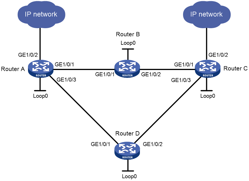
Table 5 Interface and IP address assignment
|
Interface |
IP address |
Device |
Interface |
IP address |
|
|
Router A |
Loop0 |
1.1.1.9/32 |
Router D |
Loop0 |
4.4.4.9/32 |
|
|
GE1/0/1 |
10.1.1.1/24 |
|
GE1/0/1 |
30.1.1.2/24 |
|
|
GE1/0/2 |
100.1.1.1/24 |
|
GE1/0/2 |
40.1.1.1/24 |
|
|
GE1/0/3 |
30.1.1.1/24 |
Router C |
Loop0 |
3.3.3.9/32 |
|
Router B |
Loop0 |
2.2.2.9/32 |
|
GE1/0/1 |
20.1.1.2/24 |
|
|
GE1/0/1 |
10.1.1.2/24 |
|
GE1/0/2 |
100.1.2.1/24 |
|
|
GE1/0/2 |
20.1.1.1/24 |
|
GE1/0/3 |
40.1.1.2/24 |
Procedure
1. Configure IP addresses and masks for interfaces. (Details not shown.)
2. Configure IS-IS to advertise interface addresses, including the loopback interface address, and configure IS-IS TE. (Details not shown.)
3. Configure an LSR ID, and enable MPLS, MPLS TE, and RSVP-TE:
# Configure Router A.
<RouterA> system-view
[RouterA] mpls lsr-id 1.1.1.9
[RouterA] mpls te
[RouterA-te] quit
[RouterA] rsvp
[RouterA-rsvp] quit
[RouterA] interface gigabitethernet 1/0/1
[RouterA-GigabitEthernet1/0/1] mpls enable
[RouterA-GigabitEthernet1/0/1] mpls te enable
[RouterA-GigabitEthernet1/0/1] rsvp enable
[RouterA-GigabitEthernet1/0/1] quit
[RouterA] interface gigabitethernet 1/0/3
[RouterA-GigabitEthernet1/0/3] mpls enable
[RouterA-GigabitEthernet1/0/3] mpls te enable
[RouterA-GigabitEthernet1/0/3] rsvp enable
[RouterA-GigabitEthernet1/0/3] quit
# Configure Router B, Router C, and Router D in the same way that Router A is configured. (Details not shown.)
4. Configure an MPLS TE tunnel on Router A:
# Configure MPLS TE tunnel interface Tunnel 3.
[RouterA] interface tunnel 3 mode mpls-te
[RouterA-Tunnel3] ip address 9.1.1.1 255.255.255.0
# Specify the tunnel destination address as the LSR ID of Router C.
[RouterA-Tunnel3] destination 3.3.3.9
# Configure MPLS TE to use RSVP-TE to establish the tunnel.
[RouterA-Tunnel3] mpls te signaling rsvp-te
# Enable CRLSP hot backup for the tunnel.
[RouterA-Tunnel3] mpls te backup hot-standby
[RouterA-Tunnel3] quit
5. Configure a static route on Router A to direct the traffic destined for subnet 100.1.2.0/24 to MPLS TE tunnel 3.
[RouterA] ip route-static 100.1.2.0 24 tunnel 3 preference 1
Verifying the configuration
# Verify that the tunnel interface Tunnel 3 is up on Router A.
[RouterA] display interface tunnel
Tunnel3
Current state: UP
Line protocol state: UP
Description: Tunnel3 Interface
Bandwidth: 64kbps
Maximum transmission unit: 1496
Internet address: 9.1.1.1/24 (primary)
Tunnel source unknown, destination 3.3.3.9
Tunnel TTL 255
Tunnel protocol/transport CR_LSP
Output queue - Urgent queuing: Size/Length/Discards 0/100/0
Output queue - Protocol queuing: Size/Length/Discards 0/500/0
Output queue - FIFO queuing: Size/Length/Discards 0/75/0
Last clearing of counters: Never
Last 300 seconds input rate: 0 bytes/sec, 0 bits/sec, 0 packets/sec
Last 300 seconds output rate: 0 bytes/sec, 0 bits/sec, 0 packets/sec
Input: 0 packets, 0 bytes, 0 drops
Output: 0 packets, 0 bytes, 0 drops
# Verify that two CRLSPs exist on Router A, one with the output interface GigabitEthernet 1/0/1 and the other with the output interface GigabitEthernet 1/0/3.
[RouterA] display mpls lsp
FEC Proto In/Out Label Interface/Out NHLFE
1.1.1.9/3/34311 RSVP -/1150 GE1/0/1
1.1.1.9/3/34312 RSVP -/1151 GE1/0/3
10.1.1.2 Local -/- GE1/0/1
30.1.1.2 Local -/- GE1/0/3
Tunnel3 Local -/- NHLFE1026
Backup -/- NHLFE1028
# Display the paths used by the two CRLSPs on Router A.
[RouterA] display rsvp lsp verbose
Tunnel name: RouterA_t3
Destination: 3.3.3.9 Source: 1.1.1.9
Tunnel ID: 3 LSP ID: 30106
LSR type: Ingress Direction: Unidirectional
Setup priority: 7 Holding priority: 7
In-Label: - Out-Label: 1137
In-Interface: - Out-Interface: GE1/0/1
Nexthop: 10.1.1.2 Exclude-any: 0
Include-Any: 0 Include-all: 0
Mean rate (CIR): 0 kbps Mean burst size (CBS): 1000.00 bytes
Path MTU: 1500 Class type: CT0
RRO number: 6
10.1.1.1/32 Flag: 0x00 (No FRR)
10.1.1.2/32 Flag: 0x00 (No FRR/In-Int)
2.2.2.9/32 Flag: 0x20 (No FRR/Node-ID)
20.1.1.1/32 Flag: 0x00 (No FRR)
20.1.1.2/32 Flag: 0x00 (No FRR/In-Int)
3.3.3.9/32 Flag: 0x20 (No FRR/Node-ID)
Fast Reroute protection: None
Tunnel name: Tunnel3
Destination: 3.3.3.9 Source: 1.1.1.9
Tunnel ID: 3 LSP ID: 30107
LSR type: Ingress Direction: Unidirectional
Setup priority: 7 Holding priority: 7
In-Label: - Out-Label: 1150
In-Interface: - Out-Interface: GE1/0/3
Nexthop: 30.1.1.2 Exclude-any: 0
Include-Any: 0 Include-all: 0
Mean rate (CIR): 0 kbps Mean burst size (CBS): 1000.00 bytes
Path MTU: 1500 Class type: CT0
RRO number: 6
30.1.1.1/32 Flag: 0x00 (No FRR)
30.1.1.2/32 Flag: 0x00 (No FRR/In-Int)
4.4.4.9/32 Flag: 0x20 (No FRR/Node-ID)
40.1.1.1/32 Flag: 0x00 (No FRR)
40.1.1.2/32 Flag: 0x00 (No FRR/In-Int)
3.3.3.9/32 Flag: 0x20 (No FRR/Node-ID)
Fast Reroute protection: None
# Trace the path that MPLS TE tunnel 3 traverses. The output shows that the used CRLSP is the one that traverses Router B.
[RouterA] tracert mpls te tunnel 3
MPLS trace route TE tunnel Tunnel3
TTL Replier Time Type Downstream
0 Ingress 10.1.1.2/[1147]
1 10.1.1.2 1 ms Transit 20.1.1.2/[3]
2 20.1.1.2 2 ms Egress
# Shut down interface GigabitEthernet 1/0/2 on Router B, and then tracert tunnel 3. The output shows that packets are forwarded on the CRLSP that traverses Router D.
[RouterA] tracert mpls te tunnel 3
MPLS trace route TE tunnel Tunnel3
TTL Replier Time Type Downstream
0 Ingress 30.1.1.2/[1148]
1 30.1.1.2 2 ms Transit 40.1.1.2/[3]
2 40.1.1.2 3 ms Egress
# Verify that only one CRLSP exists on Router A.
[RouterA] display mpls lsp
FEC Proto In/Out Label Interface/Out NHLFE
1.1.1.9/3/34313 RSVP -/1150 GE1/0/3
30.1.1.2 Local -/- GE1/0/3
Tunnel3 Local -/- NHLFE1029
# Execute the display ip routing-table command on Router A. The output shows a static route entry with interface Tunnel 3 as the output interface. (Details not shown.)
Example: Configuring manual bypass tunnel for FRR
Network configuration
On the primary CRLSP Router A—Router B—Router C—Router D, use FRR to protect the link Router B—Router C.
Use RSVP-TE to establish the primary CRLSP and bypass tunnel based on the constraints of the explicit paths to transmit data between the two IP networks. The bypass tunnel uses path Router B—Router E—Router C. Router B is the PLR and Router C is the MP.
Configure BFD for RSVP-TE between Router B and Router C. When the link between Router B and Router C fails, BFD can detect the failure quickly and notify RSVP-TE of the failure, so RSVP-TE can switch traffic to the bypass tunnel.
Figure 15 Network diagram
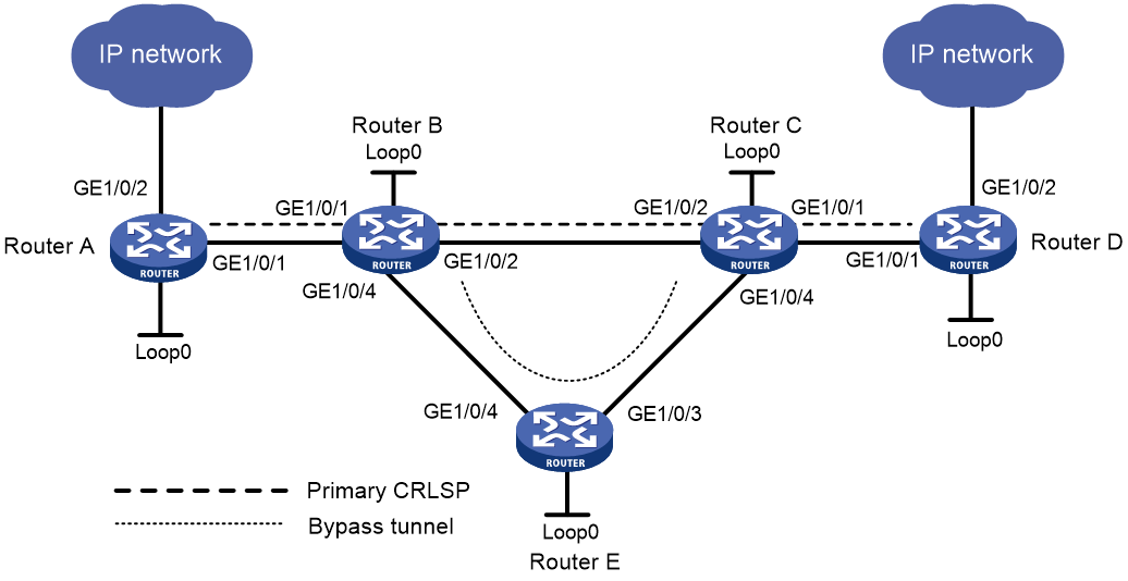
Table 6 Interface and IP address assignment
|
Interface |
IP address |
Device |
Interface |
IP address |
|
|
Router A |
Loop0 |
1.1.1.1/32 |
Router B |
Loop0 |
2.2.2.2/32 |
|
|
GE1/0/1 |
2.1.1.1/24 |
|
GE1/0/1 |
2.1.1.2/24 |
|
|
GE1/0/2 |
100.1.1.1/24 |
|
GE1/0/2 |
3.1.1.1/24 |
|
Router D |
Loop0 |
4.4.4.4/32 |
|
GE1/0/4 |
3.2.1.1/24 |
|
|
GE1/0/1 |
4.1.1.2/24 |
Router C |
Loop0 |
3.3.3.3/32 |
|
|
GE1/0/2 |
100.1.2.1/24 |
|
GE1/0/1 |
4.1.1.1/24 |
|
Router E |
Loop0 |
5.5.5.5/32 |
|
GE1/0/2 |
3.1.1.2/24 |
|
|
GE1/0/3 |
3.3.1.1/24 |
|
GE1/0/4 |
3.3.1.2/24 |
|
|
GE1/0/4 |
3.2.1.2/24 |
|
|
|
Procedure
1. Configure IP addresses and masks for interfaces. (Details not shown.)
2. Configure IS-IS to advertise interface addresses, including the loopback interface address. (Details not shown.)
3. Configure an LSR ID, and enable MPLS, MPLS TE, and RSVP-TE on each router. Enable BFD for RSVP-TE on Router B and Router C:
# Configure Router A.
<RouterA> system-view
[RouterA] mpls lsr-id 1.1.1.1
[RouterA] mpls te
[RouterA-te] quit
[RouterA] rsvp
[RouterA-rsvp] quit
[RouterA] interface gigabitethernet 1/0/1
[RouterA-GigabitEthernet1/0/1] mpls enable
[RouterA-GigabitEthernet1/0/1] mpls te enable
[RouterA-GigabitEthernet1/0/1] rsvp enable
[RouterA-GigabitEthernet1/0/1] quit
# Configure Router B.
<RouterB> system-view
[RouterB] mpls lsr-id 2.2.2.2
[RouterB] mpls te
[RouterB-te] quit
[RouterB] rsvp
[RouterB-rsvp] quit
[RouterB] interface gigabitethernet 1/0/1
[RouterB-GigabitEthernet1/0/1] mpls enable
[RouterB-GigabitEthernet1/0/1] mpls te enable
[RouterB-GigabitEthernet1/0/1] rsvp enable
[RouterB-GigabitEthernet1/0/1] quit
[RouterB] interface gigabitethernet 1/0/2
[RouterB-GigabitEthernet1/0/2] mpls enable
[RouterB-GigabitEthernet1/0/2] mpls te enable
[RouterB-GigabitEthernet1/0/2] rsvp enable
[RouterB-GigabitEthernet1/0/2] rsvp bfd enable
[RouterB-GigabitEthernet1/0/2] quit
[RouterB] interface gigabitethernet 1/0/4
[RouterB-GigabitEthernet1/0/4] mpls enable
[RouterB-GigabitEthernet1/0/4] mpls te enable
[RouterB-GigabitEthernet1/0/4] rsvp enable
[RouterB-GigabitEthernet1/0/4] quit
# Configure Router C in the same way that Router B is configured. Configure Router D and Router E in the same way that Router A is configured. (Details not shown.)
4. Configure IS-IS TE:
# Configure Router A.
[RouterA] isis 1
[RouterA-isis-1] cost-style wide
[RouterA-isis-1] mpls te enable level-2
[RouterA-isis-1] quit
# Configure Router B.
[RouterB] isis 1
[RouterB-isis-1] cost-style wide
[RouterB-isis-1] mpls te enable level-2
[RouterB-isis-1] quit
# Configure Router C.
[RouterC] isis 1
[RouterC-isis-1] cost-style wide
[RouterC-isis-1] mpls te enable level-2
[RouterC-isis-1] quit
# Configure Router D.
[RouterD] isis 1
[RouterD-isis-1] cost-style wide
[RouterD-isis-1] mpls te enable level-2
[RouterD-isis-1] quit
# Configure Router E.
[RouterE] isis 1
[RouterE-isis-1] cost-style wide
[RouterE-isis-1] mpls te enable level-2
[RouterE-isis-1] quit
5. Configure an MPLS TE tunnel on Router A, the ingress node of the primary CRLSP:
# Configure an explicit path for the primary CRLSP.
[RouterA] explicit-path pri-path
[RouterA-explicit-path-pri-path] nexthop 2.1.1.2
[RouterA-explicit-path-pri-path] nexthop 3.1.1.2
[RouterA-explicit-path-pri-path] nexthop 4.1.1.2
[RouterA-explicit-path-pri-path] nexthop 4.4.4.4
[RouterA-explicit-path-pri-path] quit
# Create MPLS TE tunnel interface Tunnel 4 for the primary CRLSP.
[RouterA] interface tunnel 4 mode mpls-te
[RouterA-Tunnel4] ip address 10.1.1.1 255.255.255.0
# Specify the tunnel destination address as the LSR ID of Router D.
[RouterA-Tunnel4] destination 4.4.4.4
# Specify the tunnel signaling protocol as RSVP-TE.
[RouterA-Tunnel4] mpls te signaling rsvp-te
# Specify the explicit path as pri-path.
[RouterA-Tunnel4] mpls te path preference 1 explicit-path pri-path
# Enable FRR for the MPLS TE tunnel.
[RouterA-Tunnel4] mpls te fast-reroute
[RouterA-Tunnel4] quit
# Verify that the tunnel interface Tunnel 4 is up on Router A.
[RouterA] display interface tunnel
Tunnel4
Current state: UP
Line protocol state: UP
Description: Tunnel4 Interface
Bandwidth: 64kbps
Maximum transmission unit: 1496
Internet address: 10.1.1.1/24 (primary)
Tunnel source unknown, destination 4.4.4.4
Tunnel TTL 255
Tunnel protocol/transport CR_LSP
Output queue - Urgent queuing: Size/Length/Discards 0/1024/0
Output queue - Protocol queuing: Size/Length/Discards 0/500/0
Output queue - FIFO queuing: Size/Length/Discards 0/75/0
Last clearing of counters: Never
Last 300 seconds input rate: 0 bytes/sec, 0 bits/sec, 0 packets/sec
Last 300 seconds output rate: 1911 bytes/sec, 15288 bits/sec, 0 packets/sec
Input: 0 packets, 0 bytes, 0 drops
Output: 1526 packets, 22356852 bytes, 0 drops
# Display detailed information about the MPLS TE tunnel on Router A.
[RouterA] display mpls te tunnel-interface
Tunnel Name : Tunnel 4
Tunnel State : Up (Main CRLSP up, Shared-resource CRLSP down)
Tunnel Attributes :
LSP ID : 48960 Tunnel ID : 4
Admin State : Normal
Ingress LSR ID : 1.1.1.1 Egress LSR ID : 3.3.3.3
Signaling : RSVP-TE Static CRLSP Name : -
Static SRLSP Name : -
Resv Style : SE
Tunnel mode : -
Reverse-LSP name : -
Reverse-LSP LSR ID : - Reverse-LSP Tunnel ID: -
Class Type : CT0 Tunnel Bandwidth : 0 kbps
Reserved Bandwidth : 0 kbps
Setup Priority : 7 Holding Priority : 7
Affinity Attr/Mask : 0/0
Explicit Path : pri-path
Backup Explicit Path : -
Metric Type : TE
Record Route : Enabled Record Label : Enabled
FRR Flag : Enabled Bandwidth Protection : Disabled
Backup Bandwidth Flag: Disabled Backup Bandwidth Type: -
Backup Bandwidth : -
Bypass Tunnel : No Auto Created : No
Route Pinning : Disabled
Retry Limit : 10 Retry Interval : 2 sec
Reoptimization : Disabled Reoptimization Freq : -
Backup Type : None Backup LSP ID : -
Auto Bandwidth : Disabled Auto Bandwidth Freq : -
Min Bandwidth : - Max Bandwidth : -
Collected Bandwidth : - Service-Class : -
6. Configure a bypass tunnel on Router B (the PLR):
# Configure an explicit path for the bypass tunnel.
[RouterB] explicit-path by-path
[RouterB-explicit-path-by-path] nexthop 3.2.1.2
[RouterB-explicit-path-by-path] nexthop 3.3.1.2
[RouterB-explicit-path-by-path] nexthop 3.3.3.3
[RouterB-explicit-path-by-path] quit
# Create MPLS TE tunnel interface Tunnel 5 for the bypass tunnel.
[RouterB] interface tunnel 5 mode mpls-te
[RouterB-Tunnel5] ip address 11.1.1.1 255.255.255.0
# Specify the tunnel destination address as LSR ID of Router C.
[RouterB-Tunnel5] destination 3.3.3.3
# Specify the tunnel signaling protocol as RSVP-TE.
[RouterB-Tunnel5] mpls te signaling rsvp-te
# Specify the explicit path to be used as by-path.
[RouterB-Tunnel5] mpls te path preference 1 explicit-path by-path
# Set the bandwidth that the bypass tunnel can protect.
[RouterB-Tunnel5] mpls te backup bandwidth un-limited
[RouterB-Tunnel5] quit
# Bind the bypass tunnel to the protected interface.
[RouterB] interface gigabitethernet 1/0/2
[RouterB-GigabitEthernet1/0/2] mpls te fast-reroute bypass-tunnel tunnel 5
[RouterB-GigabitEthernet1/0/2] quit
# Execute the display interface tunnel command on Router B. The output shows that the tunnel interface Tunnel 5 is up. (Details not shown.)
7. Configure a static route on Router A to direct the traffic destined for subnet 100.1.2.0/24 to MPLS TE tunnel 4.
[RouterA] ip route-static 100.1.2.0 24 tunnel 4 preference 1
Verifying the configuration
# Display LSP entries on each router to verify that Router B and Router C each have two CRLSPs and the bypass tunnel backs up the primary CRLSP.
[RouterA] display mpls lsp
FEC Proto In/Out Label Interface/Out NHLFE
1.1.1.1/4/48960 RSVP -/1245 GE1/0/1
2.1.1.2 Local -/- GE1/0/1
[RouterB] display mpls lsp
FEC Proto In/Out Label Interface/Out NHLFE
1.1.1.1/4/48960 RSVP 1245/3 GE1/0/2
Backup 1245/3 Tun5
2.2.2.2/5/31857 RSVP -/3 GE1/0/2
3.2.1.2 Local -/- GE1/0/4
3.1.1.2 Local -/- GE1/0/2
# Shut down the protected interface GigabitEthernet 1/0/2 on the PLR (Router B).
[RouterB] interface gigabitethernet 1/0/2
[RouterB-GigabitEthernet1/0/2] shutdown
[RouterB-GigabitEthernet1/0/2] quit
# Execute the display interface tunnel 4 command on Router A to display information about the primary CRLSP. The output shows that the tunnel interface is still up. (Details not shown.)
# Display detailed information about the tunnel interface on Router A.
[RouterA] display mpls te tunnel-interface
Tunnel Name : Tunnel 4
Tunnel State : Up (Main CRLSP up, Shared-resource CRLSP being set up)
Tunnel Attributes :
LSP ID : 18753 Tunnel ID : 4
Admin State : Normal
Ingress LSR ID : 1.1.1.1 Egress LSR ID : 3.3.3.3
Signaling : RSVP-TE Static CRLSP Name : -
Static SRLSP Name : -
Resv Style : SE
Tunnel mode : -
Reverse-LSP name : -
Reverse-LSP LSR ID : - Reverse-LSP Tunnel ID: -
Class Type : CT0 Tunnel Bandwidth : 0 kbps
Reserved Bandwidth : 0 kbps
Setup Priority : 7 Holding Priority : 7
Affinity Attr/Mask : 0/0
Explicit Path : pri-path
Backup Explicit Path : -
Metric Type : TE
Record Route : Enabled Record Label : Enabled
FRR Flag : Enabled Bandwidth Protection : Disabled
Backup Bandwidth Flag: Disabled Backup Bandwidth Type: -
Backup Bandwidth : -
Bypass Tunnel : No Auto Created : No
Route Pinning : Disabled
Retry Limit : 10 Retry Interval : 2 sec
Reoptimization : Disabled Reoptimization Freq : -
Backup Type : None Backup LSP ID : -
Auto Bandwidth : Disabled Auto Bandwidth Freq : -
Min Bandwidth : - Max Bandwidth : -
Collected Bandwidth : - Service-Class : -
|
|
NOTE: If you execute the display mpls te tunnel-interface command immediately after an FRR, you can see two CRLSPs in up state. This is because FRR uses the make-before-break mechanism to set up a new LSP, and the old LSP is deleted after the new one has been established for a while. |
# Verify that the bypass tunnel is in use on Router B.
[RouterB] display mpls lsp
FEC Proto In/Out Label Interface/Out NHLFE
1.1.1.1/4/18753 RSVP 1122/3 Tun5
2.2.2.2/5/40312 RSVP -/1150 GE1/0/4
3.2.1.2 Local -/- GE1/0/4
# On the PLR, set the interval for selecting an optimal bypass tunnel to 5 seconds.
[RouterB] mpls te
[RouterB-te] fast-reroute timer 5
[RouterB-te] quit
# On the PLR, bring up the protected interface GigabitEthernet 1/0/2.
[RouterB] interface gigabitethernet 1/0/2
[RouterB-GigabitEthernet1/0/2] undo shutdown
[RouterB-GigabitEthernet1/0/2] quit
# Execute the display interface tunnel 4 command on Router A to display information about the primary CRLSP. The output shows that the tunnel interface is in up state. (Details not shown.)
# Wait for about 5 seconds, execute the display mpls lsp verbose command on Router B. The output shows that Tunnel 5 is bound to interface GigabitEthernet 1/0/2 but not in use. (Details not shown.)
# Execute the display ip routing-table command on Router A. The output shows a static route entry with interface Tunnel 4 as the output interface. (Details not shown.)
Example: Configuring auto FRR
Network configuration
Use RSVP-TE to set up a primary CRLSP that explicitly uses path Router A—Router B—Router C—Router D.
Configure auto FRR on Router B to automatically set up bypass tunnels for the primary CRLSP.
Configure BFD for RSVP-TE between Router B and Router C. When the link between Router B and Router C fails, BFD can detect the failure quickly and notify RSVP-TE of the failure, so RSVP-TE can switch traffic to the bypass tunnel.
Figure 16 Network diagram
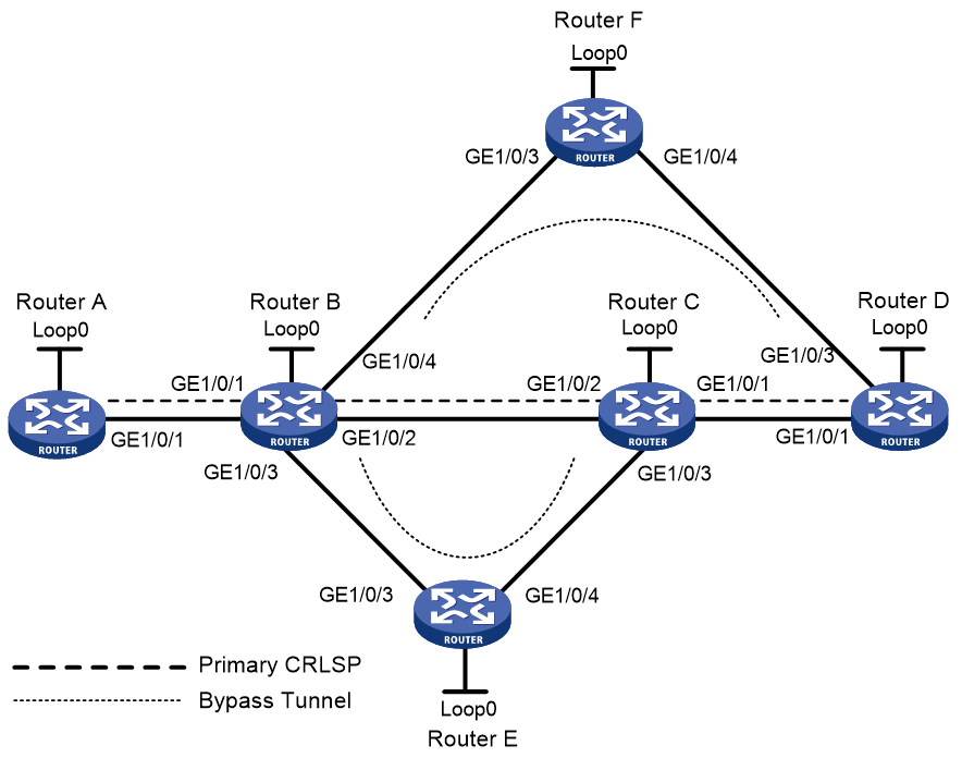
Table 7 Interface and IP address assignment
|
Device |
Interface |
IP address |
Device |
Interface |
IP address |
|
Router A |
Loop0 |
1.1.1.1/32 |
Router E |
Loop0 |
5.5.5.5/32 |
|
|
GE1/0/1 |
2.1.1.1/24 |
|
GE1/0/3 |
3.2.1.2/24 |
|
Router B |
Loop0 |
2.2.2.2/32 |
|
GE1/0/4 |
3.4.1.1/24 |
|
|
GE1/0/1 |
2.1.1.2/24 |
Router C |
Loop0 |
3.3.3.3/32 |
|
|
GE1/0/2 |
3.1.1.1/24 |
|
GE1/0/1 |
4.1.1.1/24 |
|
|
GE1/0/3 |
3.2.1.1/24 |
|
GE1/0/2 |
3.1.1.2/24 |
|
|
GE1/0/4 |
3.3.1.1/24 |
|
GE1/0/3 |
3.4.1.2/24 |
|
Router D |
Loop0 |
4.4.4.4/32 |
Router F |
Loop0 |
6.6.6.6/32 |
|
|
GE1/0/1 |
4.1.1.2/24 |
|
GE1/0/3 |
3.3.1.2/24 |
|
|
GE1/0/3 |
4.2.1.2/24 |
|
GE1/0/4 |
4.2.1.1/24 |
Procedure
1. Configure IP addresses and masks for interfaces. (Details not shown.)
2. Configure IS-IS to advertise interface addresses, including the loopback interface address. (Details not shown.)
3. Configure an LSR ID, and enable MPLS, MPLS TE, and RSVP-TE on each router. Enable BFD for RSVP-TE on Router B and Router C:
# Configure Router A.
<RouterA> system-view
[RouterA] mpls lsr-id 1.1.1.1
[RouterA] mpls te
[RouterA-te] quit
[RouterA] rsvp
[RouterA-rsvp] quit
[RouterA] interface gigabitethernet 1/0/1
[RouterA-GigabitEthernet1/0/1] mpls enable
[RouterA-GigabitEthernet1/0/1] mpls te enable
[RouterA-GigabitEthernet1/0/1] rsvp enable
[RouterA-GigabitEthernet1/0/1] quit
# Configure Router B.
<RouterB> system-view
[RouterB] mpls lsr-id 2.2.2.2
[RouterB] mpls te
[RouterB-te] quit
[RouterB] rsvp
[RouterB-rsvp] quit
[RouterB] interface gigabitethernet 1/0/1
[RouterB-GigabitEthernet1/0/1] mpls enable
[RouterB-GigabitEthernet1/0/1] mpls te enable
[RouterB-GigabitEthernet1/0/1] rsvp enable
[RouterB-GigabitEthernet1/0/1] quit
[RouterB] interface gigabitethernet 1/0/2
[RouterB-GigabitEthernet1/0/2] mpls enable
[RouterB-GigabitEthernet1/0/2] mpls te enable
[RouterB-GigabitEthernet1/0/2] rsvp enable
[RouterB-GigabitEthernet1/0/2] rsvp bfd enable
[RouterB-GigabitEthernet1/0/2] quit
[RouterB] interface gigabitethernet 1/0/3
[RouterB-GigabitEthernet1/0/3] mpls enable
[RouterB-GigabitEthernet1/0/3] mpls te enable
[RouterB-GigabitEthernet1/0/3] rsvp enable
[RouterB-GigabitEthernet1/0/3] quit
[RouterB] interface gigabitethernet 1/0/4
[RouterB-GigabitEthernet1/0/4] mpls enable
[RouterB-GigabitEthernet1/0/4] mpls te enable
[RouterB-GigabitEthernet1/0/4] rsvp enable
[RouterB-GigabitEthernet1/0/4] quit
# Configure Router C in the same way that Router B is configured. Configure Router D, Router E, and Router F in the same way that Router A is configured. (Details not shown.)
4. Configure IS-IS TE:
# Configure Router A.
[RouterA] isis 1
[RouterA-isis-1] cost-style wide
[RouterA-isis-1] mpls te enable level-2
[RouterA-isis-1] quit
# Configure Router B.
[RouterB] isis 1
[RouterB-isis-1] cost-style wide
[RouterB-isis-1] mpls te enable level-2
[RouterB-isis-1] quit
# Configure Router C.
[RouterC] isis 1
[RouterC-isis-1] cost-style wide
[RouterC-isis-1] mpls te enable level-2
[RouterC-isis-1] quit
# Configure Router D.
[RouterD] isis 1
[RouterD-isis-1] cost-style wide
[RouterD-isis-1] mpls te enable level-2
[RouterD-isis-1] quit
# Configure Router E.
[RouterE] isis 1
[RouterE-isis-1] cost-style wide
[RouterE-isis-1] mpls te enable level-2
[RouterE-isis-1] quit
# Configure Router F.
[RouterF] isis 1
[RouterF-isis-1] cost-style wide
[RouterF-isis-1] mpls te enable level-2
[RouterF-isis-1] quit
5. Configure an MPLS TE tunnel on Router A, the ingress node of the primary CRLSP:
# Configure an explicit path named pri-path for the primary CRLSP.
[RouterA] explicit-path pri-path
[RouterA-explicit-path-pri-path] nexthop 2.1.1.2
[RouterA-explicit-path-pri-path] nexthop 3.1.1.2
[RouterA-explicit-path-pri-path] nexthop 4.1.1.2
[RouterA-explicit-path-pri-path] nexthop 4.4.4.4
[RouterA-explicit-path-pri-path] quit
# Create MPLS TE tunnel interface Tunnel 1 for the primary CRLSP.
[RouterA] interface tunnel 1 mode mpls-te
[RouterA-Tunnel1] ip address 10.1.1.1 255.255.255.0
# Specify the tunnel destination address as the LSR ID of Router D.
[RouterA-Tunnel1] destination 4.4.4.4
# Specify the tunnel signaling protocol as RSVP-TE.
[RouterA-Tunnel1] mpls te signaling rsvp-te
# Specify the explicit path as pri-path.
[RouterA-Tunnel1] mpls te path preference 1 explicit-path pri-path
# Enable FRR for the MPLS TE tunnel.
[RouterA-Tunnel1] mpls te fast-reroute
[RouterA-Tunnel1] quit
# Verify that the MPLS TE interface Tunnel 1 is up on Router A.
[RouterA] display interface tunnel
Tunnel1
Current state: UP
Line protocol state: UP
Description: Tunnel4 Interface
Bandwidth: 64kbps
Maximum transmission unit: 1496
Internet address: 10.1.1.1/24 (primary)
Tunnel source unknown, destination 4.4.4.4
Tunnel TTL 255
Tunnel protocol/transport CR_LSP
Output queue - Urgent queuing: Size/Length/Discards 0/1024/0
Output queue - Protocol queuing: Size/Length/Discards 0/500/0
Output queue - FIFO queuing: Size/Length/Discards 0/75/0
Last clearing of counters: Never
Last 300 seconds input rate: 0 bytes/sec, 0 bits/sec, 0 packets/sec
Last 300 seconds output rate: 1911 bytes/sec, 15288 bits/sec, 0 packets/sec
Input: 0 packets, 0 bytes, 0 drops
Output: 1526 packets, 22356852 bytes, 0 drops
# Display detailed information about the MPLS TE tunnel interface on Router A.
[RouterA] display mpls te tunnel-interface
Tunnel Name : Tunnel 1
Tunnel State : Up (Main CRLSP up, Shared-resource CRLSP down)
Tunnel Attributes :
LSP ID : 16802 Tunnel ID : 1
Admin State : Normal
Ingress LSR ID : 1.1.1.1 Egress LSR ID : 4.4.4.4
Signaling : RSVP-TE Static CRLSP Name : -
Static SRLSP Name : -
Resv Style : SE
Tunnel mode : -
Reverse-LSP name : -
Reverse-LSP LSR ID : - Reverse-LSP Tunnel ID: -
Class Type : CT0 Tunnel Bandwidth : 0 kbps
Reserved Bandwidth : 0 kbps
Setup Priority : 7 Holding Priority : 7
Affinity Attr/Mask : 0/0
Explicit Path : pri-path
Backup Explicit Path : -
Metric Type : TE
Record Route : Enabled Record Label : Enabled
FRR Flag : Enabled Bandwidth Protection : Disabled
Backup Bandwidth Flag: Disabled Backup Bandwidth Type: -
Backup Bandwidth : -
Bypass Tunnel : No Auto Created : No
Route Pinning : Disabled
Retry Limit : 3 Retry Interval : 2 sec
Reoptimization : Disabled Reoptimization Freq : -
Backup Type : None Backup LSP ID : -
Auto Bandwidth : Disabled Auto Bandwidth Freq : -
Min Bandwidth : - Max Bandwidth : -
Collected Bandwidth : - Service-Class : -
6. Configure auto FRR on Router B (the PLR):
# Enable the automatic bypass tunnel setup feature globally.
[RouterB] mpls te
[RouterB-te] auto-tunnel backup
# Specify interface numbers 50 to 100 for the automatically created bypass tunnels.
[RouterB-te-auto-bk] tunnel-number min 50 max 100
[RouterB-te-auto-bk] quit
Verifying the configuration
# Verify that two tunnels have been created automatically on Router B.
[RouterB] display interface tunnel brief
Brief information on interfaces in route mode:
Link: ADM - administratively down; Stby - standby
Protocol: (s) - spoofing
Interface Link Protocol Primary IP Description
Tun50 UP DOWN --
Tun51 UP DOWN --
# Display information about Tunnel 50 and Tunnel 51 on Router B. The output shows that Tunnel 50 and Tunnel 51 are automatically created bypass tunnels. Tunnel 50 is a node-protection bypass tunnel (egress LSR ID is 4.4.4.4, the LSR ID of Router D). Tunnel 51 is a link-protection bypass tunnel (egress LSR ID is 3.3.3.3, the LSR ID of Router C).
[RouterB] display mpls te tunnel-interface tunnel 50
Tunnel Name : Tunnel 50
Tunnel State : Up (Main CRLSP up, Shared-resource CRLSP down)
Tunnel Attributes :
LSP ID : 16802 Tunnel ID : 50
Admin State : Normal
Ingress LSR ID : 2.2.2.2 Egress LSR ID : 4.4.4.4
Signaling : RSVP-TE Static CRLSP Name : -
Static SRLSP Name : -
Resv Style : SE
Tunnel mode : -
Reverse-LSP name : -
Reverse-LSP LSR ID : - Reverse-LSP Tunnel ID: -
Class Type : CT0 Tunnel Bandwidth : 0 kbps
Reserved Bandwidth : 0 kbps
Setup Priority : 7 Holding Priority : 7
Affinity Attr/Mask : 0/0
Explicit Path : -
Backup Explicit Path : -
Metric Type : TE
Record Route : Enabled Record Label : Disabled
FRR Flag : Disabled Bandwidth Protection : Disabled
Backup Bandwidth Flag: Disabled Backup Bandwidth Type: -
Backup Bandwidth : -
Bypass Tunnel : Yes Auto Created : Yes
Route Pinning : Disabled
Retry Limit : 3 Retry Interval : 2 sec
Reoptimization : Disabled Reoptimization Freq : -
Backup Type : None Backup LSP ID : -
Auto Bandwidth : Disabled Auto Bandwidth Freq : -
Min Bandwidth : - Max Bandwidth : -
Collected Bandwidth : - Service-Class : -
[RouterB] display mpls te tunnel-interface tunnel 51
Tunnel Name : Tunnel 51
Tunnel State : Up (Main CRLSP up, Shared-resource CRLSP down)
Tunnel Attributes :
LSP ID : 16802 Tunnel ID : 51
Admin State : Normal
Ingress LSR ID : 2.2.2.2 Egress LSR ID : 3.3.3.3
Signaling : RSVP-TE Static CRLSP Name : -
Static SRLSP Name : -
Resv Style : SE
Tunnel mode : -
Reverse-LSP name : -
Reverse-LSP LSR ID : - Reverse-LSP Tunnel ID: -
Class Type : CT0 Tunnel Bandwidth : 0 kbps
Reserved Bandwidth : 0 kbps
Setup Priority : 7 Holding Priority : 7
Affinity Attr/Mask : 0/0
Explicit Path : -
Backup Explicit Path : -
Metric Type : TE
Record Route : Enabled Record Label : Disabled
FRR Flag : Disabled Bandwidth Protection : Disabled
Backup Bandwidth Flag: Disabled Backup Bandwidth Type: -
Backup Bandwidth : -
Bypass Tunnel : Yes Auto Created : Yes
Route Pinning : Disabled
Retry Limit : 3 Retry Interval : 2 sec
Reoptimization : Disabled Reoptimization Freq : -
Backup Type : None Backup LSP ID : -
Auto Bandwidth : Disabled Auto Bandwidth Freq : -
Min Bandwidth : - Max Bandwidth : -
Collected Bandwidth : - Service-Class : -
# Verify that the current bypass tunnel that protects the primary CRLSP is Tunnel 50.
[RouterB] display mpls lsp
FEC Proto In/Out Label Interface/Out NHLFE
2.2.2.2/51/16802 RSVP -/3 GE1/0/3
2.2.2.2/1/16802 RSVP -/1151 GE1/0/2
Backup -/3 Tun50
2.2.2.2/50/16802 RSVP -/3 GE1/0/4
3.2.1.2 Local -/- GE1/0/4
3.3.1.2 Local -/- GE1/0/3
# Display detailed information about MPLS TE tunnel 1 (the tunnel for the primary CRLSP) on Router B. The output shows that Tunnel1 is protected by the bypass tunnel Tunnel50, and the protected node is 3.1.1.1.
[RouterB] display rsvp lsp tunnel-id 1 verbose
Tunnel name: Tunnel1
Destination: 4.4.4.4 Source: 1.1.1.1
Tunnel ID: 1 LSP ID: 16802
LSR type: Transit Direction: Unidirectional
Setup priority: 7 Holding priority: 7
In-Label: 1150 Out-Label: 1151
In-Interface: GE1/0/1 Out-Interface: GE1/0/2
Nexthop: 3.1.1.2 Exclude-any: 0
Include-Any: 0 Include-all: 0
Average bitrate: 0 kbps Maximum burst: 1000.00 bytes
Path MTU: 1500 Class type: CT0
RRO number: 12
2.1.1.1/32 Flag: 0x00 (No FRR)
2.1.1.2/32 Flag: 0x00 (No FRR)
1150 Flag: 0x01 (Global label)
2.2.2.2/32 Flag: 0x20 (No FRR/Node-ID)
3.1.1.1/32 Flag: 0x09 (FRR Avail/Node-Prot)
3.1.1.2/32 Flag: 0x00 (No FRR)
1151 Flag: 0x01 (Global label)
3.3.3.3/32 Flag: 0x20 (No FRR/Node-ID)
4.1.1.1/32 Flag: 0x00 (No FRR)
4.1.1.2/32 Flag: 0x00 (No FRR)
3 Flag: 0x01 (Global label)
4.4.4.4/32 Flag: 0x20 (No FRR/Node-ID)
Fast Reroute protection: Ready
FRR inner label: 3 Bypass tunnel: Tunnel50
Example: Configuring IETF DS-TE
Network configuration
Router A, Router B, Router C, and Router D run IS-IS and all of them are Level-2 routers.
Use RSVP-TE to establish an MPLS TE tunnel from Router A to Router D to transmit data between the two IP networks. Traffic of the tunnel belongs to CT 2, and the tunnel needs a bandwidth of 4000 kbps.
The maximum bandwidth of the link that the tunnel traverses is 10000 kbps and the maximum reservable bandwidth of the link is 10000 kbps. BC 1, BC 2, and BC 3 are 8000 kbps, 5000 kbps, and 2000 kbps.
Figure 17 Network diagram
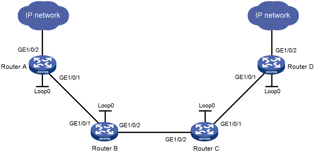
Table 8 Interface and IP address assignment
|
Device |
Interface |
IP address |
Device |
Interface |
IP address |
|
Router A |
Loop0 |
1.1.1.9/32 |
Router C |
Loop0 |
3.3.3.9/32 |
|
|
GE1/0/1 |
10.1.1.1/24 |
|
GE1/0/1 |
30.1.1.1/24 |
|
|
GE1/0/2 |
100.1.1.1/24 |
|
GE1/0/2 |
20.1.1.2/24 |
|
Router B |
Loop0 |
2.2.2.9/32 |
Router D |
Loop0 |
4.4.4.9/32 |
|
|
GE1/0/1 |
10.1.1.2/24 |
|
GE1/0/1 |
30.1.1.2/24 |
|
|
GE1/0/2 |
20.1.1.1/24 |
|
GE1/0/2 |
100.1.2.1/24 |
Procedure
1. Configure IP addresses and masks for interfaces. (Details not shown.)
2. Configure IS-IS to advertise interface addresses, including the loopback interface address:
# Configure Router A.
<RouterA> system-view
[RouterA] isis 1
[RouterA-isis-1] network-entity 00.0005.0000.0000.0001.00
[RouterA-isis-1] quit
[RouterA] interface gigabitethernet 1/0/1
[RouterA-GigabitEthernet1/0/1] isis enable 1
[RouterA-GigabitEthernet1/0/1] isis circuit-level level-2
[RouterA-GigabitEthernet1/0/1] quit
[RouterA] interface loopback 0
[RouterA-LoopBack0] isis enable 1
[RouterA-LoopBack0] isis circuit-level level-2
[RouterA-LoopBack0] quit
# Configure Router B.
<RouterB> system-view
[RouterB] isis 1
[RouterB-isis-1] network-entity 00.0005.0000.0000.0002.00
[RouterB-isis-1] quit
[RouterB] interface gigabitethernet 1/0/1
[RouterB-GigabitEthernet1/0/1] isis enable 1
[RouterB-GigabitEthernet1/0/1] isis circuit-level level-2
[RouterB-GigabitEthernet1/0/1] quit
[RouterB] interface gigabitethernet 1/0/2
[RouterB-GigabitEthernet1/0/2] isis enable 1
[RouterB-GigabitEthernet1/0/2] isis circuit-level level-2
[RouterB-GigabitEthernet1/0/2] quit
[RouterB] interface loopback 0
[RouterB-LoopBack0] isis enable 1
[RouterB-LoopBack0] isis circuit-level level-2
[RouterB-LoopBack0] quit
# Configure Router C.
<RouterC> system-view
[RouterC] isis 1
[RouterC-isis-1] network-entity 00.0005.0000.0000.0003.00
[RouterC-isis-1] quit
[RouterC] interface gigabitethernet 1/0/1
[RouterC-GigabitEthernet1/0/1] isis enable 1
[RouterC-GigabitEthernet1/0/1] isis circuit-level level-2
[RouterC-GigabitEthernet1/0/1] quit
[RouterC] interface gigabitethernet 1/0/2
[RouterC-GigabitEthernet1/0/2] isis enable 1
[RouterC-GigabitEthernet1/0/2] isis circuit-level level-2
[RouterC-GigabitEthernet1/0/2] quit
[RouterC] interface loopback 0
[RouterC-LoopBack0] isis enable 1
[RouterC-LoopBack0] isis circuit-level level-2
[RouterC-LoopBack0] quit
# Configure Router D.
<RouterD> system-view
[RouterD] isis 1
[RouterD-isis-1] network-entity 00.0005.0000.0000.0004.00
[RouterD-isis-1] quit
[RouterD] interface gigabitethernet 1/0/1
[RouterD-GigabitEthernet1/0/1] isis enable 1
[RouterD-GigabitEthernet1/0/1] isis circuit-level level-2
[RouterD-GigabitEthernet1/0/1] quit
[RouterD] interface loopback 0
[RouterD-LoopBack0] isis enable 1
[RouterD-LoopBack0] isis circuit-level level-2
[RouterD-LoopBack0] quit
# Verify that the routers have learned the routes to one another, including the routes to the loopback interfaces. This example uses Router A.
[RouterA] display ip routing-table
Destinations : 10 Routes : 10
Destination/Mask Proto Pre Cost NextHop Interface
1.1.1.9/32 Direct 0 0 127.0.0.1 InLoop0
2.2.2.9/32 IS_L1 15 10 10.1.1.2 GE1/0/1
3.3.3.9/32 IS_L1 15 20 10.1.1.2 GE1/0/1
4.4.4.9/32 IS_L1 15 30 10.1.1.2 GE1/0/1
10.1.1.0/24 Direct 0 0 10.1.1.1 GE1/0/1
10.1.1.1/32 Direct 0 0 127.0.0.1 InLoop0
20.1.1.0/24 IS_L1 15 20 10.1.1.2 GE1/0/1
30.1.1.0/24 IS_L1 15 30 10.1.1.2 GE1/0/1
127.0.0.0/8 Direct 0 0 127.0.0.1 InLoop0
127.0.0.1/32 Direct 0 0 127.0.0.1 InLoop0
3. Configure an LSR ID, enable MPLS, MPLS TE, and RSVP-TE, and configure the DS-TE mode as IETF:
# Configure Router A.
[RouterA] mpls lsr-id 1.1.1.9
[RouterA] mpls te
[RouterA-te] ds-te mode ietf
[RouterA-te] quit
[RouterA] rsvp
[RouterA-rsvp] quit
[RouterA] interface gigabitethernet 1/0/1
[RouterA-GigabitEthernet1/0/1] mpls enable
[RouterA-GigabitEthernet1/0/1] mpls te enable
[RouterA-GigabitEthernet1/0/1] rsvp enable
[RouterA-GigabitEthernet1/0/1] quit
# Configure Router B.
[RouterB] mpls lsr-id 2.2.2.9
[RouterB] mpls te
[RouterB-te] ds-te mode ietf
[RouterB-te] quit
[RouterB] rsvp
[RouterB-rsvp] quit
[RouterB] interface gigabitethernet 1/0/1
[RouterB-GigabitEthernet1/0/1] mpls enable
[RouterB-GigabitEthernet1/0/1] mpls te enable
[RouterB-GigabitEthernet1/0/1] rsvp enable
[RouterB-GigabitEthernet1/0/1] quit
[RouterB] interface gigabitethernet 1/0/2
[RouterB-GigabitEthernet1/0/2] mpls enable
[RouterB-GigabitEthernet1/0/2] mpls te enable
[RouterB-GigabitEthernet1/0/2] rsvp enable
[RouterB-GigabitEthernet1/0/2] quit
# Configure Router C.
[RouterC] mpls lsr-id 3.3.3.9
[RouterC] mpls te
[RouterC-te] ds-te mode ietf
[RouterC-te] quit
[RouterC] rsvp
[RouterC-rsvp] quit
[RouterC] interface gigabitethernet 1/0/1
[RouterC-GigabitEthernet1/0/1] mpls enable
[RouterC-GigabitEthernet1/0/1] mpls te enable
[RouterC-GigabitEthernet1/0/1] rsvp enable
[RouterC-GigabitEthernet1/0/1] quit
[RouterC] interface gigabitethernet 1/0/2
[RouterC-GigabitEthernet1/0/2] mpls enable
[RouterC-GigabitEthernet1/0/2] mpls te enable
[RouterC-GigabitEthernet1/0/2] rsvp enable
[RouterC-GigabitEthernet1/0/2] quit
# Configure Router D.
[RouterD] mpls lsr-id 4.4.4.9
[RouterD] mpls te
[RouterD-te] ds-te mode ietf
[RouterD-te] quit
[RouterD] rsvp
[RouterD-rsvp] quit
[RouterD] interface gigabitethernet 1/0/1
[RouterD-GigabitEthernet1/0/1] mpls enable
[RouterD-GigabitEthernet1/0/1] mpls te enable
[RouterD-GigabitEthernet1/0/1] rsvp enable
[RouterD-GigabitEthernet1/0/1] quit
4. Enable IS-IS TE, and configure IS-IS to receive and send only packets whose cost style is wide:
# Configure Router A.
[RouterA] isis 1
[RouterA-isis-1] cost-style wide
[RouterA-isis-1] mpls te enable level-2
[RouterA-isis-1] quit
# Configure Router B.
[RouterB] isis 1
[RouterB-isis-1] cost-style wide
[RouterB-isis-1] mpls te enable level-2
[RouterB-isis-1] quit
# Configure Router C.
[RouterC] isis 1
[RouterC-isis-1] cost-style wide
[RouterC-isis-1] mpls te enable level-2
[RouterC-isis-1] quit
# Configure Router D.
[RouterD] isis 1
[RouterD-isis-1] cost-style wide
[RouterD-isis-1] mpls te enable level-2
[RouterD-isis-1] quit
5. Configure MPLS TE attributes of links:
# Set the maximum bandwidth, maximum reservable bandwidth, and bandwidth constraints on Router A.
[RouterA] interface gigabitethernet 1/0/1
[RouterA-GigabitEthernet1/0/1] mpls te max-link-bandwidth 10000
[RouterA-GigabitEthernet1/0/1] mpls te max-reservable-bandwidth rdm 10000 bc1 8000 bc2 5000 bc3 2000
[RouterA-GigabitEthernet1/0/1] quit
# Set the maximum bandwidth, maximum reservable bandwidth, and bandwidth constraints on Router B.
[RouterB] interface gigabitethernet 1/0/1
[RouterB-GigabitEthernet1/0/1] mpls te max-link-bandwidth 10000
[RouterB-GigabitEthernet1/0/1] mpls te max-reservable-bandwidth rdm 10000 bc1 8000 bc2 5000 bc3 2000
[RouterB-GigabitEthernet1/0/1] quit
[RouterB] interface gigabitethernet 1/0/2
[RouterB-GigabitEthernet1/0/2] mpls te max-link-bandwidth 10000
[RouterB-GigabitEthernet1/0/2] mpls te max-reservable-bandwidth rdm 10000 bc1 8000 bc2 5000 bc3 2000
[RouterB-GigabitEthernet1/0/2] quit
# Set the maximum bandwidth, maximum reservable bandwidth, and bandwidth constraints on Router C.
[RouterC] interface gigabitethernet 1/0/1
[RouterC-GigabitEthernet1/0/1] mpls te max-link-bandwidth 10000
[RouterC-GigabitEthernet1/0/1] mpls te max-reservable-bandwidth rdm 10000 bc1 8000 bc2 5000 bc3 2000
[RouterC-GigabitEthernet1/0/1] quit
[RouterC] interface gigabitethernet 1/0/2
[RouterC-GigabitEthernet1/0/2] mpls te max-link-bandwidth 10000
[RouterC-GigabitEthernet1/0/2] mpls te max-reservable-bandwidth rdm 10000 bc1 8000 bc2 5000 bc3 2000
[RouterC-GigabitEthernet1/0/2] quit
# Set the maximum bandwidth, maximum reservable bandwidth, and bandwidth constraints on Router D.
[RouterD] interface gigabitethernet 1/0/1
[RouterD-GigabitEthernet1/0/1] mpls te max-link-bandwidth 10000
[RouterD-GigabitEthernet1/0/1] mpls te max-reservable-bandwidth rdm 10000 bc1 8000 bc2 5000 bc3 2000
[RouterD-GigabitEthernet1/0/1] quit
6. Configure an MPLS TE tunnel on Router A:
# Create MPLS TE tunnel interface Tunnel 1.
[RouterA] interface tunnel 1 mode mpls-te
[RouterA-Tunnel1] ip address 7.1.1.1 255.255.255.0
# Specify the tunnel destination address as the LSR ID of Router D.
[RouterA-Tunnel1] destination 4.4.4.9
# Configure MPLS TE to use RSVP-TE to establish the tunnel.
[RouterA-Tunnel1] mpls te signaling rsvp-te
# Assign 4000 kbps bandwidth to CT 2 for the tunnel.
[RouterA-Tunnel1] mpls te bandwidth ct2 4000
# Set the tunnel setup priority and holding priority both to 0.
[RouterA-Tunnel1] mpls te priority 0
[RouterA-Tunnel1] quit
7. Configure a static route on Router A to direct the traffic destined for subnet 100.1.2.0/24 to MPLS TE tunnel 1.
[RouterA] ip route-static 100.1.2.0 24 tunnel 1 preference 1
Verifying the configuration
# Verify that the tunnel interface is up on Router A.
[RouterA] display interface tunnel
Tunnel1
Current state: UP
Line protocol state: UP
Description: Tunnel1 Interface
Bandwidth: 64kbps
Maximum transmission unit: 1496
Internet address: 7.1.1.1/24 (primary)
Tunnel source unknown, destination 4.4.4.9
Tunnel TTL 255
Tunnel protocol/transport CR_LSP
Output queue - Urgent queuing: Size/Length/Discards 0/1024/0
Output queue - Protocol queuing: Size/Length/Discards 0/500/0
Output queue - FIFO queuing: Size/Length/Discards 0/75/0
Last clearing of counters: Never
Last 300 seconds input rate: 0 bytes/sec, 0 bits/sec, 0 packets/sec
Last 300 seconds output rate: 0 bytes/sec, 0 bits/sec, 0 packets/sec
Input: 0 packets input, 0 bytes 0 drops
Output: 0 packets output, 0 bytes 0 drops
# Display detailed information about the MPLS TE tunnel on Router A.
[RouterA] display mpls te tunnel-interface
Tunnel Name : Tunnel 1
Tunnel State : Up (Main CRLSP up, Shared-resource CRLSP down)
Tunnel Attributes :
LSP ID : 36882 Tunnel ID : 1
Admin State : Normal
Ingress LSR ID : 1.1.1.9 Egress LSR ID : 4.4.4.9
Signaling : RSVP-TE Static CRLSP Name : -
Static SRLSP Name : -
Resv Style : SE
Tunnel mode : -
Reverse-LSP name : -
Reverse-LSP LSR ID : - Reverse-LSP Tunnel ID: -
Class Type : CT2 Tunnel Bandwidth : 4000 kbps
Reserved Bandwidth : 4000 kbps
Setup Priority : 0 Holding Priority : 0
Affinity Attr/Mask : 0/0
Explicit Path : -
Backup Explicit Path : -
Metric Type : TE
Record Route : Disabled Record Label : Disabled
FRR Flag : Disabled Bandwidth Protection : Disabled
Backup Bandwidth Flag: Disabled Backup Bandwidth Type: -
Backup Bandwidth : -
Bypass Tunnel : No Auto Created : No
Route Pinning : Disabled
Retry Limit : 10 Retry Interval : 2 sec
Reoptimization : Disabled Reoptimization Freq : -
Backup Type : None Backup LSP ID : -
Auto Bandwidth : Disabled Auto Bandwidth Freq : -
Min Bandwidth : - Max Bandwidth : -
Collected Bandwidth : - Service-Class : -
# Display bandwidth information on interface GigabitEthernet 1/0/1 on Router A.
[RouterA] display mpls te link-management bandwidth-allocation interface gigabitethernet 1/0/1
Interface: GigabitEthernet1/0/1
Max Link Bandwidth : 10000 kbps
Max Reservable Bandwidth of Prestandard RDM : 0 kbps
Max Reservable Bandwidth of IETF RDM : 10000 kbps
Max Reservable Bandwidth of IETF MAM : 0 kbps
Allocated Bandwidth-Item Count : 1
Allocated Bandwidth : 4000 kbps
Physical Link Status : Up
BC Prestandard RDM(kbps) IETF RDM(kbps) IETF MAM(kbps)
0 0 10000 0
1 0 8000 0
2 - 5000 0
3 - 2000 0
TE Class Class Type Priority BW Reserved(kbps) BW Available(kbps)
0 0 7 0 6000
1 1 7 0 4000
2 2 7 0 1000
3 3 7 0 1000
4 0 0 0 6000
5 1 0 0 4000
6 2 0 4000 1000
# Execute the display ip routing-table command on Router A. The output shows a static route entry with interface Tunnel1 as the output interface. (Details not shown.)
Example: Configuring CBTS
Network configuration
As shown in Figure 18, all routers run IS-IS.
Use RSVP-TE to establish the following MPLS TE tunnels between Router A and Router E:
· Router A—Router B—Router E.
· Router A—Router C—Router E.
· Router A—Router D—Router E.
Assign the MPLS TE tunnels different service class values for different classes of services.
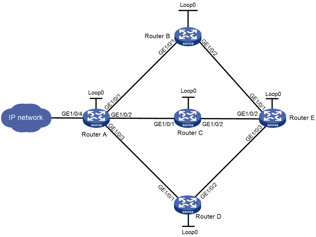
Table 9 Interface and IP address assignment
|
Device |
Interface |
IP address |
Device |
Interface |
IP address |
|
Router A |
Loop0 |
1.1.1.1/32 |
Router D |
Loop0 |
4.4.4.4/32 |
|
|
GE1/0/1 |
10.1.1.1/24 |
|
GE1/0/1 |
30.1.1.2/24 |
|
|
GE1/0/2 |
20.1.1.1/24 |
|
GE1/0/2 |
40.1.1.1/24 |
|
|
GE1/0/3 |
30.1.1.1/24 |
Router E |
Loop0 |
5.5.5.5/32 |
|
|
GE1/0/4 |
100.1.1.1/24 |
|
GE1/0/1 |
100.1.1.2/24 |
|
Router B |
Loop0 |
2.2.2.2/32 |
|
GE1/0/2 |
200.1.1.2/24 |
|
|
GE1/0/1 |
10.1.1.2/24 |
|
GE1/0/3 |
40.1.1.1.2/24 |
|
|
GE1/0/2 |
100.1.1.1/24 |
|
|
|
|
Router C |
Loop0 |
3.3.3.3/32 |
|
|
|
|
|
GE1/0/1 |
20.1.1.2/24 |
|
|
|
|
|
GE1/0/2 |
200.1.1.1/24 |
|
|
|
Procedure
1. Configure IP addresses and masks for interfaces, including the loopback interfaces, as shown in Figure 18. (Details not shown.)
2. Configure IS-IS to advertise interface addresses including loopback interface addresses, and configure IS-IS TE. (Details not shown.)
3. Configure an LSR ID, and enable MPLS, MPLS TE, and RSVP-TE on each router. (Details not shown.)
4. Use RSVP-TE to establish three MPLS TE tunnels: Tunnel 1, Tunnel 2, and Tunnel 3. Tunnel 1 uses path Router A—Router B—Router E. Tunnel 2 uses path Router A—Router C—Router E. Tunnel 3 uses path Router A—Router D—Router E. (Details not shown.)
5. Configure a QoS policy on Router A.
# Create a traffic class.
<RouterA> system-view
[RouterA] traffic classifier class
[RouterA-classifier-class] if-match any
[RouterA-classifier-class] quit
# Create a traffic behavior.
[RouterA] traffic behavior behave
[RouterA-behavior-behave] remark service-class 3
[RouterA-behavior-behave] quit
# Create a QoS policy.
[RouterA] qos policy policy
[RouterA-qospolicy-policy] classifier class behavior behave
[RouterA-qospolicy-policy] quit
# Apply the QoS policy to GigabitEthernet 1/0/4.
[RouterA] interface gigabitethernet 1/0/4
[RouterA-GigabitEthernet1/0/4] qos apply policy policy inbound
[RouterA-GigabitEthernet1/0/4] quit
6. Set the service class values for the MPLS TE tunnels.
# Set the service class value to 3 for Tunnel 2.
[RouterA]interface Tunnel 2 mode mpls-te
[RouterA-Tunnel2] mpls te service-class 3
[RouterA-Tunnel2] quit
# Set the service class value to 6 for Tunnel 3.
[RouterA]interface Tunnel 3 mode mpls-te
[RouterA-Tunnel3] mpls te service-class 6
[RouterA-Tunnel3] quit
Verifying the configuration
# Display information about Tunnel 1 on Router A.
[RouterA] display mpls te tunnel-interface Tunnel 1
Tunnel Name : Tunnel 1
Tunnel State : Up (Main CRLSP up)
Tunnel Attributes :
LSP ID : 17419 Tunnel ID : 1
Admin State : Normal
Ingress LSR ID : 10.1.1.1 Egress LSR ID : 40.1.1.1
Signaling : RSVP-TE Static CRLSP Name : -
Static SRLSP Name : -
Resv Style : -
Tunnel mode : -
Reverse-LSP name : -
Reverse-LSP LSR ID : - Reverse-LSP Tunnel ID: -
Class Type : - Tunnel Bandwidth : -
Reserved Bandwidth : -
Setup Priority : 0 Holding Priority : 0
Affinity Attr/Mask : -/-
Explicit Path : -
Backup Explicit Path : -
Metric Type : TE
Record Route : - Record Label : -
FRR Flag : - Bandwidth Protection : -
Backup Bandwidth Flag: - Backup Bandwidth Type: -
Backup Bandwidth : -
Bypass Tunnel : - Auto Created : -
Route Pinning : -
Retry Limit : 3 Retry Interval : 2 sec
Reoptimization : - Reoptimization Freq : -
Backup Type : - Backup LSP ID : -
Auto Bandwidth : - Auto Bandwidth Freq : -
Min Bandwidth : - Max Bandwidth : -
Collected Bandwidth : - Service-Class : -
The Service-Class field has no value, indicating that no service class value is set for Tunnel 1.
# Display information about Tunnel 2 and Tunnel 3 on Router A.
[RouterA]display mpls te tunnel-interface Tunnel 2
Tunnel Name : Tunnel 2
Tunnel State : Up (Main CRLSP up)
Tunnel Attributes :
LSP ID : 17418 Tunnel ID : 2
Admin State : Normal
Ingress LSR ID : 10.1.1.1 Egress LSR ID : 40.1.1.1
Signaling : RSVP-TE Static CRLSP Name : -
Static SRLSP Name : -
Resv Style : -
Tunnel mode : -
Reverse-LSP name : -
Reverse-LSP LSR ID : - Reverse-LSP Tunnel ID: -
Class Type : - Tunnel Bandwidth : -
Reserved Bandwidth : -
Setup Priority : 0 Holding Priority : 0
Affinity Attr/Mask : -/-
Explicit Path : -
Backup Explicit Path : -
Metric Type : TE
Record Route : - Record Label : -
FRR Flag : - Bandwidth Protection : -
Backup Bandwidth Flag: - Backup Bandwidth Type: -
Backup Bandwidth : -
Bypass Tunnel : - Auto Created : -
Route Pinning : -
Retry Limit : 3 Retry Interval : 2 sec
Reoptimization : - Reoptimization Freq : -
Backup Type : - Backup LSP ID : -
Auto Bandwidth : - Auto Bandwidth Freq : -
Min Bandwidth : - Max Bandwidth : -
Collected Bandwidth : - Service-Class : 3
[RouterA]display mpls te tunnel-interface Tunnel 3
Tunnel Name : Tunnel 3
Tunnel State : Up (Main CRLSP up)
Tunnel Attributes :
LSP ID : 17418 Tunnel ID : 3
Admin State : Normal
Ingress LSR ID : 10.1.1.1 Egress LSR ID : 40.1.1.1
Signaling : RSVP-TE Static CRLSP Name : -
Static SRLSP Name : -
Resv Style : -
Tunnel mode : -
Reverse-LSP name : -
Reverse-LSP LSR ID : - Reverse-LSP Tunnel ID: -
Class Type : - Tunnel Bandwidth : -
Reserved Bandwidth : -
Setup Priority : 0 Holding Priority : 0
Affinity Attr/Mask : -/-
Explicit Path : -
Backup Explicit Path : -
Metric Type : TE
Record Route : - Record Label : -
FRR Flag : - Bandwidth Protection : -
Backup Bandwidth Flag: - Backup Bandwidth Type: -
Backup Bandwidth : -
Bypass Tunnel : - Auto Created : -
Route Pinning : -
Retry Limit : 3 Retry Interval : 2 sec
Reoptimization : - Reoptimization Freq : -
Backup Type : - Backup LSP ID : -
Auto Bandwidth : - Auto Bandwidth Freq : -
Min Bandwidth : - Max Bandwidth : -
Collected Bandwidth : - Service-Class : 6
The Service-Class fields show that the service class values of Tunnel 2 and Tunnel 3 are 3 and 6, respectively. According to the QoS policy, traffic arrives at GigabitEthernet 1/0/4 of Router A is assigned service class value 3. So CBTS uses Tunnel 2 to forward the traffic.
Troubleshooting MPLS TE
No TE LSA generated
Symptom
OSPF TE is configured but no TE LSAs can be generated to describe MPLS TE attributes.
Analysis
For TE LSAs to be generated, a minimum of one OSPF neighbor must reach FULL state.
Solution
1. To resolve the problem:
a. Use the display current-configuration command to verify that MPLS TE is configured on involved interfaces.
b. Use the debugging ospf mpls-te command to verify that OSPF can receive the TE LINK establishment message.
c. Use the display ospf peer command to verify that OSPF neighbors are established correctly.
2. If the problem persists, contact H3C Support.