- Table of Contents
-
- 07-Layer 3—IP Services Configuration Guide
- 00-Preface
- 01-ARP configuration
- 02-IP addressing configuration
- 03-DHCP configuration
- 04-DNS configuration
- 05-NAT configuration
- 06-NAT66 configuration
- 07-IP forwarding basics configuration
- 08-Fast forwarding configuration
- 09-Multi-CPU packet distribution configuration
- 10-Adjacency table configuration
- 11-IRDP configuration
- 12-IP performance optimization configuration
- 13-UDP helper configuration
- 14-IPv6 basics configuration
- 15-DHCPv6 configuration
- 16-IPv6 fast forwarding configuration
- 17-AFT configuration
- 18-Tunneling configuration
- 19-GRE configuration
- 20-ADVPN configuration
- 21-WAAS configuration
- 22-Lighttpd service configuration
- 23-Web caching configuration
- Related Documents
-
| Title | Size | Download |
|---|---|---|
| 18-Tunneling configuration | 513.94 KB |
Contents
Supported tunneling technologies
Restrictions and guidelines: Tunnel interface configuration
Configuring a tunnel interface
About tunnel interface configuration
Tunnel interface configuration tasks at a glance
Specifying traffic processing slots for the tunnel interface
Configuring parameters for tunneled packets
Specifying the tunnel destination VPN instance
Restoring the default settings of the tunnel interface
Specifying an output interface for tunneled packets
Display and maintenance commands for tunnel interface configuration
Troubleshooting tunnel interface configuration
About IPv6 over IPv4 tunneling
IPv6 over IPv4 tunneling tasks at a glance
Configuring an IPv6 over IPv4 manual tunnel
Example: Configuring an IPv6 over IPv4 manual tunnel
Configuring an automatic IPv4-compatible IPv6 tunnel
Example: Configuring an automatic IPv4-compatible IPv6 tunnel
Example: Configuring a 6to4 tunnel
Example: Configuring 6to4 relay
Example: Configuring an ISATAP tunnel
Display and maintenance commands for 6RD tunneling
Example: Configuring a 6RD tunnel
Example: Configuring 6RD relay
Enabling dropping IPv6 packets that use IPv4-compatible IPv6 addresses
About IPv4 over IPv4 tunneling
Restrictions and guidelines: IPv4 over IPv4 tunnel configuration
Configuring an IPv4 over IPv4 tunnel
IPv4 over IPv4 tunnel configuration examples
Example: Configuring an IPv4 over IPv4 tunnel
About IPv4 over IPv6 tunneling
Configuring an IPv4 over IPv6 manual tunnel
Example: Configuring an IPv4 over IPv6 tunnel
Restrictions and guidelines for DS-Lite tunnel configuration
Configuring the B4 router of a DS-Lite tunnel
Configuring the AFTR of a DS-Lite tunnel
Example: Configuring a DS-Lite tunnel
About IPv6 over IPv6 tunneling
Restrictions and guidelines: IPv6 over IPv6 tunnel configuration
IPv6 over IPv6 tunnel configuration tasks at a glance
Configuring an IPv6 over IPv6 tunnel
Enabling dropping IPv6 packets that use IPv4-compatible IPv6 addresses
IPv6 over IPv6 tunnel configuration examples
Example: Configuring an IPv6 over IPv6 tunnel
Configuring tunneling
This chapter describes tunnel interface configuration. For information about tunnel modes, see the subsequent chapters.
About tunneling
Tunneling encapsulates the packets of a network protocol within the packets of a second network protocol and transfers them over a virtual point-to-point connection. The virtual connection is called a tunnel. Packets are encapsulated at the tunnel source and de-encapsulated at the tunnel destination.
Supported tunneling technologies
Tunneling supports the following technologies:
· ADVPN tunneling. For more information, see "Configuring ADVPN."
· EVI tunneling. For more information, see EVI Configuration Guide.
· GRE tunneling. For more information, see "Configuring GRE."
· MPLS TE tunneling. For more information, see MPLS Configuration Guide.
· IPsec tunneling. For more information, see Security Configuration Guide.
· VXLAN tunneling. For more information, see VXLAN Configuration Guide.
· IPv6 over IPv4 tunneling, IPv4 over IPv4 tunneling, and IPv4/IPv6 over IPv6 tunneling.
Restrictions and guidelines: Tunnel interface configuration
Configuring a tunnel interface
About tunnel interface configuration
Configure a tunnel interface (Layer 3 virtual interface) at both ends of a tunnel. The devices use the tunnel interface to identify, process, and send packets for the tunnel.
Tunnel interface configuration tasks at a glance
To configure a tunnel interface, perform the following tasks:
1. Creating a tunnel interface
2. (Optional.) Specifying traffic processing slots for the tunnel interface
3. (Optional.) Configuring parameters for tunneled packets
4. (Optional.) Specifying the tunnel destination VPN instance
5. (Optional.) Restoring the default settings of the tunnel interface
6. (Optional.) Specifying an output interface for tunneled packets
Creating a tunnel interface
1. Enter system view.
system-view
2. Create a tunnel interface, specify the tunnel mode, and enter tunnel interface view.
interface tunnel number mode { advpn { gre | udp } [ ipv6 ] | ds-lite-aftr | gre [ ipv6 ] | gre-p2mp [ ipv6 ] | ipsec [ ipv6 ] | ipv4-ipv4 | ipv6 | ipv6-ipv4 [ 6rd | 6to4 | auto-tunnel | isatap ] | mgre | mpls-te | nve | vxlan [ ipv6 ] }
For packet tunneling to succeed, the two ends of a tunnel must use the same tunnel mode.
3. Configure a source address or source interface for the tunnel interface.
source { ipv4-address | ipv6-address | interface-type interface-number }
By default, no source address or source interface is configured for the tunnel interface.
If you specify a source address, it is used as the source address of tunneled packets.
If you specify a source interface, the primary IP address of this interface is used as the source IP address of tunneled packets.
4. Configure a destination address for the tunnel interface.
destination { ipv4-address | ipv6-address | dhcp-alloc interface-type interface-number }
By default, no destination address is configured for the tunnel interface.
The tunnel destination address must be the IP address of the receiving interface on the tunnel peer. It is used as the destination IP address of tunneled packets.
5. (Optional.) Configure a description for the interface.
description text
By default, the description for a tunnel interface is Tunnel number Interface.
6. (Optional.) Set the MTU of the tunnel interface.
mtu size
The default settings are as follows:
¡ If the tunnel interface has never been up, the MTU is 64000 bytes.
¡ If the tunnel interface is up, its MTU is identical to the outgoing interface's MTU minus the length of the tunnel headers. The outgoing interface is automatically obtained through routing table lookup based on the tunnel destination address.
7. (Optional.) Set the expected bandwidth for the tunnel interface.
bandwidth bandwidth-value
The default expected bandwidth (in kbps) is the interface maximum rate divided by 1000.
The expected bandwidth is an informational parameter used only by higher-layer protocols for calculation. You cannot adjust the actual bandwidth of an interface by using this command.
8. Bring up the tunnel interface.
undo shutdown
By default, a tunnel interface is not administratively down.
Specifying traffic processing slots for the tunnel interface
About this task
Specify a traffic processing slot if a feature (for example, IPsec antireplay) requires that all traffic on a tunnel interface be processed on the same slot.
For high availability, you can specify one primary and one backup traffic processing slot by using the service command and the service standby command, respectively.
If you specify both primary and backup slots for an interface, traffic on that interface is processed as follows:
· The backup slot takes over when the primary slot becomes unavailable. The backup slot continues to process traffic for the interface after the primary slot becomes available again. The switchover will not occur until the backup slot becomes unavailable.
· When no specified traffic processing slots are available, the traffic is processed on the slot at which it arrives. Then, the processing slot that first becomes available again takes over.
If you do not specify a primary or a backup traffic processing slot for an interface, traffic on that interface is processed on the slot at which the traffic arrives.
Hardware and feature compatibility
|
Hardware |
Feature compatibility |
|
MSR810, MSR810-W, MSR810-W-DB, MSR810-LM, MSR810-W-LM, MSR810-10-PoE, MSR810-LM-HK, MSR810-W-LM-HK, MSR810-LM-CNDE-SJK, MSR810-CNDE-SJK |
No |
|
MSR810-LMS, MSR810-LUS |
No |
|
MSR810-LMS-EA, MSR810-LME |
No |
|
MSR2600-6-X1, MSR2600-10-X1 |
No |
|
MSR 2630 |
Yes |
|
MSR3600-28, MSR3600-51 |
Yes |
|
MSR3600-28-SI, MSR3600-51-SI |
No |
|
MSR3600-28-X1, MSR3600-28-X1-DP, MSR3600-51-X1, MSR3600-51-X1-DP |
Yes |
|
MSR3610-I-DP, MSR3610-IE-DP, MSR3610-IE-ES, MSR3610-IE-EAD |
No |
|
MSR3610-X1, MSR3610-X1-DP, MSR3610-X1-DC, MSR3610-X1-DP-DC |
Yes |
|
MSR 3610, MSR 3620, MSR 3620-DP, MSR 3640, MSR 3660 |
Yes |
|
MSR3610-G, MSR3620-G |
Yes |
|
Hardware |
Feature compatibility |
|
MSR810-W-WiNet, MSR810-LM-WiNet |
No |
|
MSR830-4LM-WiNet |
No |
|
MSR830-5BEI-WiNet, MSR830-6EI-WiNet, MSR830-10BEI-WiNet |
No |
|
MSR830-6BHI-WiNet, MSR830-10BHI-WiNet |
No |
|
MSR2600-6-WiNet, MSR2600-10-X1-WiNet |
No |
|
MSR2630-WiNet |
Yes |
|
MSR3600-28-WiNet |
Yes |
|
MSR3610-X1-WiNet |
Yes |
|
MSR3610-WiNet, MSR3620-10-WiNet, MSR3620-DP-WiNet, MSR3620-WiNet, MSR3660-WiNet |
Yes |
|
Hardware |
Feature compatibility |
|
MSR2630-XS |
No |
|
MSR3600-28-XS |
Yes |
|
MSR3610-XS |
Yes |
|
MSR3620-XS |
Yes |
|
MSR3610-I-XS |
No |
|
MSR3610-IE-XS |
No |
|
Hardware |
Feature compatibility |
|
MSR810-LM-GL |
No |
|
MSR810-W-LM-GL |
No |
|
MSR830-6EI-GL |
No |
|
MSR830-10EI-GL |
No |
|
MSR830-6HI-GL |
No |
|
MSR830-10HI-GL |
No |
|
MSR2600-6-X1-GL |
No |
|
MSR3600-28-SI-GL |
No |
Restrictions and guidelines
To avoid processing slot switchover, specify the primary slot before specifying the backup slot. If you specify the backup slot before specifying the primary slot, traffic is switched over to the primary slot immediately after you specify the primary slot.
Procedure
1. Enter system view.
system-view
2. Enter tunnel interface view.
interface tunnel number
3. Specify a primary traffic processing slot for the tunnel interface.
service slot slot-number
By default, no primary traffic processing slot is specified for a tunnel interface.
4. Specify a primary traffic processing slot for the tunnel interface.
service standby slot slot-number
By default, no backup traffic processing slot is specified for a tunnel interface.
Configuring parameters for tunneled packets
1. Enter system view.
system-view
2. Enter tunnel interface view.
interface tunnel number
3. Set the ToS for tunneled packets.
tunnel tos { copy-inner-tos | tos-value }
The default settings are as follows:
¡ For VXLAN tunneled packets, the ToS is 0.
¡ For non-VXLAN tunneled packets, the ToS is the same as the ToS of the original packets.
The copy-inner-tos keyword is supported only by VXLAN tunnels.
4. Set the TTL for tunneled packets.
tunnel ttl ttl-value
The default TTL for tunneled packets is 255.
Specifying the tunnel destination VPN instance
Restrictions and guidelines
For a tunnel interface to come up, the tunnel source and destination must belong to the same VPN instance. To specify a VPN instance for the tunnel source, use the ip binding vpn-instance command on the tunnel source interface. For more information about this command, see MPLS Command Reference.
Procedure
1. Enter system view.
system-view
2. Enter tunnel interface view.
interface tunnel number
3. Specify the VPN instance to which the tunnel destination belongs.
tunnel vpn-instance vpn-instance-name
By default, the tunnel destination belongs to the public network.
Restoring the default settings of the tunnel interface
Restrictions and guidelines
|
|
CAUTION: This operation might interrupt ongoing network services. Make sure you are fully aware of the impact of this operation when you perform it on a live network. |
This operation might fail to restore the default settings for some commands for reasons such as command dependencies or system restrictions. Use the display this command in interface view to identify these commands. Use their undo forms or follow the command reference to restore their default settings. If your restoration attempt still fails, follow the error message instructions to resolve the problem.
Procedure
1. Enter system view.
system-view
2. Enter tunnel interface view.
interface tunnel number
3. Restore the default settings of the tunnel interface.
default
Specifying an output interface for tunneled packets
About this task
If ECMP routes exist, the device randomly selects an output interface to forward tunneled packets. To forward tunneled packets over a specific path, perform this task to specify the output interface for the tunneled packets.
Restrictions and guidelines
To ensure successful packet forwarding, the specified output interface must meet the following requirements:
· The interface is up.
· The interface has an IP address.
· The interface has a route to reach the destination.
This feature is applicable only to GRE and VXLAN tunnels.
Procedure
1. Enter system view.
system-view
2. Enter tunnel interface view.
interface tunnel number
3. Specify an output interface for tunneled packets.
tunnel out-interface interface-type interface-number
By default, no output interface is specified for tunneled packets. If ECMP routes exist, the device randomly selects an output interface to forward tunneled packets.
Display and maintenance commands for tunnel interface configuration
Execute display commands in any view and reset commands in user view.
|
Task |
Command |
Remarks |
|
Display information about tunnel interfaces. |
display interface [ tunnel [ number ] ] [ brief [ description | down ] ] |
N/A |
|
Display IPv6 information on tunnel interfaces. |
display ipv6 interface [ tunnel [ number ] ] [ brief ] |
For more information about this command, see IPv6 basics in Layer 3—IP Services Command Reference. |
|
Clear statistics on tunnel interfaces. |
reset counters interface [ tunnel [ number ] ] |
N/A |
|
Clear IPv6 statistics on tunnel interfaces. |
In standalone mode: reset ipv6 statistics In IRF mode: reset ipv6 statistics [ slot slot-number ] |
For more information about this command, see IPv6 basics in Layer 3—IP Services Command Reference. |
Troubleshooting tunnel interface configuration
Tunnel interface not up
Symptom
A tunnel interface configured with related parameters such as tunnel source address, tunnel destination address, and tunnel mode cannot come up.
Analysis
The physical interface of the tunnel does not come up, or the tunnel destination is unreachable.
Solution
1. To resolve the problem:
¡ Use the display interface or display ipv6 interface command to verify that the physical interface of the tunnel is up. If the physical interface is down, check the network connection.
¡ Use the display ipv6 routing-table or display ip routing-table command to verify that the tunnel destination is reachable. If the route is not available, configure a route to reach the tunnel destination.
2. If the problem persists, contact H3C Support.
IPv6 over IPv4 tunneling
About IPv6 over IPv4 tunneling
Implementation
IPv6 over IPv4 tunneling enables isolated IPv6 networks to communicate, as shown in Figure 1.
|
|
NOTE: The devices at both ends of an IPv6 over IPv4 tunnel must support the IPv4/IPv6 dual stack. |
Figure 1 IPv6 over IPv4 tunnel

The IPv6 over IPv4 tunnel processes packets by using the following steps:
1. A host in the IPv6 network sends an IPv6 packet to Device A at the tunnel source.
2. After Device A receives the IPv6 packet, it processes the packet as follows:
a. Searches the routing table to identify the outgoing interface for the IPv6 packet.
The outgoing interface is the tunnel interface, so Device A knows that the packet needs to be forwarded through the tunnel.
b. Adds an IPv4 header to the IPv6 packet and forwards the packet through the physical interface of the tunnel.
In the IPv4 header, the source IPv4 address is the IPv4 address of the tunnel source, and the destination IPv4 address is the IPv4 address of the tunnel destination.
3. Upon receiving the packet, Device B de-encapsulates the packet.
4. If the destination address of the IPv6 packet is itself, Device B forwards it to the upper-layer protocol. If it is not, Device B forwards it according to the routing table.
Tunnel modes
IPv6 over IPv4 tunnels include manually configured tunnels and automatic tunnels, depending on how the IPv4 address of the tunnel destination is obtained.
· Manually configured tunnel—The destination IPv4 address of the tunnel cannot be automatically obtained from the destination IPv6 address of an IPv6 packet at the tunnel source. It must be manually configured.
· Automatic tunnel—The destination IPv4 address of the tunnel can be automatically obtained from the destination IPv6 address (with an IPv4 address embedded) of an IPv6 packet at the tunnel source.
The source IPv4 addresses for all IPv6 over IPv4 tunnels are manually configured.
According to the way an IPv6 packet is encapsulated, IPv6 over IPv4 tunnels are divided into the modes shown in the following sections.
IPv6 over IPv4 manual tunneling
An IPv6 over IPv4 manual tunnel is a point-to-point link. To establish a manual tunnel, you must manually configure the source and destination addresses of the tunnel at both ends of the tunnel.
Manual tunneling provides the following solutions:
· Connects isolated IPv6 networks over an IPv4 network.
· Connects an IPv6 network and an IPv4/IPv6 dual-stack host over an IPv4 network.
Automatic IPv4-compatible IPv6 tunneling
An automatic IPv4-compatible IPv6 tunnel is a point-to-multipoint link. The ends of an automatic IPv4-compatible IPv6 tunnel are IPv4-compatible IPv6 addresses. The address format is 0:0:0:0:0:0:a.b.c.d/96, where a.b.c.d is an IPv4 address. The destination IPv4 address of an automatic IPv4-compatible IPv6 tunnel is embedded in the destination IPv4-compatible IPv6 address. This mechanism enables the device to automatically obtain the tunnel destination address.
Automatic IPv4-compatible IPv6 tunnels have limitations because IPv4-compatible IPv6 addresses must use globally unique IPv4 addresses.
6to4 tunneling
· Ordinary 6to4 tunneling
A 6to4 tunnel is a point-to-multipoint automatic tunnel. It is used to connect multiple isolated IPv6 networks over an IPv4 network.
The ends of a 6to4 tunnel are 6to4 addresses. The address format is 2002:abcd:efgh:subnet number::interface ID/48.
¡ 2002 is the fixed IPv6 address prefix.
¡ abcd:efgh represents a 32-bit globally unique IPv4 address in hexadecimal notation.
For example, 1.1.1.1 can be represented by 0101:0101. The IPv4 address identifies a 6to4 network (an IPv6 network where all hosts use 6to4 addresses). The border router of a 6to4 network must have the IPv4 address abcd:efgh configured on the interface connected to the IPv4 network.
¡ The subnet number identifies a subnet in the 6to4 network.
¡ The subnet number::interface ID uniquely identifies a host in the 6to4 network.
The destination IPv4 address of a 6to4 tunnel is embedded in the destination 6to4 address. This mechanism enables the device to automatically obtain the tunnel destination address.
6to4 tunneling uses an IPv4 address to identify a 6to4 network. This method overcomes the limitations of automatic IPv4-compatible IPv6 tunneling.
· 6to4 relay
6to4 relay connects a 6to4 network and an IPv6 network that uses an IP prefix other than 2002::/16. A 6to4 relay router is a gateway that forwards packets from a 6to4 network to an IPv6 network.
As shown in Figure 2, 6to4 network Site 1 communicates with IPv6 network Site 3 over a 6to4 tunnel. Configure a static route on the border router (Device A) in the 6to4 network. The next hop address must be the 6to4 address of the 6to4 relay router (Device C). Device A forwards all packets destined for the IPv6 network over the 6to4 tunnel, and Device C then forwards them to the IPv6 network.
Figure 2 Principle of 6to4 tunneling and 6to4 relay

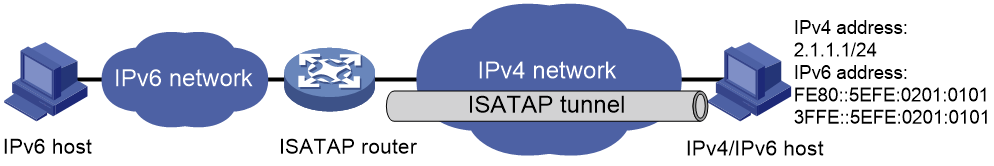
ISATAP tunneling
An ISATAP tunnel is a point-to-multipoint automatic tunnel. It provides a solution to connect an IPv6 host and an IPv6 network over an IPv4 network.
The destination address of an ISATAP tunnel is an ISATAP address. The address format is prefix:0:5EFE:abcd:efgh/64.
· The 64-bit prefix is a valid IPv6 unicast address prefix.
· The abcd:efgh/64 segments represent a 32-bit IPv4 address in hexadecimal notation, which identifies the tunnel destination but does not require global uniqueness.
ISATAP tunnels are mainly used for communication between IPv6 routers or between an IPv6 host and an IPv6 router over an IPv4 network.
Figure 3 Principle of ISATAP tunneling
6RD tunneling
· Ordinary 6RD tunneling
A 6RD tunnel is a point-to-multipoint automatic tunnel. It is an extension of 6to4 tunneling. The IPv6 prefix of a 6RD network is assigned by the service provider and is not limited to the prefix 2002::/16. 6RD does not require embedding all 32 bits of an IPv4 address in a 6RD address.
Figure 4 shows the format of 6RD address—an IPv6 address with a 6RD prefix and an embedded IPv4 address.
¡ 6RD prefix—IPv6 prefix assigned by the service provider to a 6RD network.
¡ IPv4 address—All or part of the IPv4 tunnel source address in hexadecimal notation. For example, assume that the IPv4 tunnel source address is 1.2.3.4 and both the IPv4 prefix length and suffix length are specified as 8 bits. Then, the prefix of the IPv4 address 1.2.3.4 is 01, the suffix is 04, and the embedded IPv4 address is 0203.
¡ 6RD delegated prefix—The 6RD prefix and the embedded IPv4 address together form a 6RD delegated prefix. It uniquely identifies a 6RD network (an IPv6 network where all hosts use 6RD addresses).
¡ Subnet ID—Identifies a subnet in the 6RD network.
¡ Interface ID—The subnet ID and the interface ID together identify a host in the 6RD network.
The device automatically identifies the tunnel destination IPv4 address according to the IPv4 address embedded in the 6RD address, the 6RD prefix, and the IPv4 prefix and suffix.
Figure 4 6RD address format

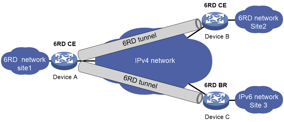
· 6RD relay
6 RD relay connects a 6RD network and an IPv6 network that uses a prefix other than a 6RD delegated prefix. A 6RD border relay (BR) router is a gateway that forwards packets from a 6RD network to an IPv6 network. The border router connected to the 6RD network is called 6RD CE.
As shown in Figure 5, for the 6RD network site 1 to communicate with the IPv6 network site 3 over a 6RD tunnel, you must configure 6RD relay. Configure a static route on the border router (Device A) in the 6RD network. The next hop address must be the 6RD address of the 6RD BR router (Device C). Device A forwards all packets destined for the IPv6 network over the 6RD tunnel, and Device C then forwards them to the IPv6 network.
Figure 5 Principle of 6RD tunneling and 6RD relay
IPv6 over IPv4 tunneling tasks at a glance
To configure IPv6 over IPv4 tunneling, perform the following tasks:
1. Configuring an IPv6 over IPv4 tunnel
Choose one of the following tasks:
¡ Configuring an IPv6 over IPv4 manual tunnel
¡ Configuring an automatic IPv4-compatible IPv6 tunnel
¡ Configuring an ISATAP tunnel
2. (Optional.) Enabling dropping IPv6 packets that use IPv4-compatible IPv6 addresses
Configuring an IPv6 over IPv4 manual tunnel
Restrictions and guidelines
When you perform tasks in this section, follow these restrictions and guidelines:
· The tunnel destination address specified on the local device must be identical with the tunnel source address specified on the tunnel peer device.
· Do not specify the same tunnel source and destination addresses for the tunnel interfaces in the same mode on a device.
· To ensure correct packet forwarding, identify whether the destination IPv6 network and the IPv6 address of the local tunnel interface are on the same subnet. If they are not, configure a route reaching the destination IPv6 network through the tunnel interface. You can configure the route by using one of the following methods:
¡ Configure a static route, and specify the local tunnel interface as the egress interface or specify the IPv6 address of the peer tunnel interface as the next hop.
¡ Enable a dynamic routing protocol on both the local and remote tunnel interfaces.
For more information about route configuration, see Layer 3—IP Routing Configuration Guide.
Procedure
1. Enter system view.
system-view
2. Enter IPv6 over IPv4 manual tunnel interface view.
interface tunnel number [ mode ipv6-ipv4 ]
3. Specify an IPv6 address for the tunnel interface.
See "Configuring basic IPv6 settings."
4. Configure a source address or source interface for the tunnel interface.
source { ipv4-address | interface-type interface-number }
By default, no source address or source interface is configured for the tunnel interface.
If you specify a source address, it is used as the source IP address of tunneled packets.
If you specify a source interface, the primary IP address of this interface is used as the source IP address of tunneled packets.
5. Configure a destination address for the tunnel interface.
destination ipv4-address
By default, no destination address is configured for the tunnel interface.
The tunnel destination address must be the IP address of the receiving interface on the tunnel peer. It is used as the destination IP address of tunneled packets.
6. (Optional.) Set the DF bit for tunneled packets.
tunnel dfbit enable
By default, the DF bit is not set for tunneled packets.
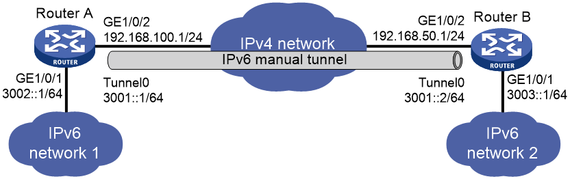
Example: Configuring an IPv6 over IPv4 manual tunnel
Network configuration
As shown in Figure 6, configure an IPv6 over IPv4 tunnel between Router A and Router B so the two IPv6 networks can reach each other over the IPv4 network. Because the tunnel destination IPv4 address cannot be automatically obtained from the destination IPv6 addresses, configure an IPv6 over IPv4 manual tunnel.
Procedure
Make sure Router A and Router B can reach each other through IPv4.
1. Configure Router A:
# Specify an IPv4 address for GigabitEthernet 1/0/2.
<RouterA> system-view
[RouterA] interface gigabitethernet 1/0/2
[RouterA-GigabitEthernet1/0/2] ip address 192.168.100.1 255.255.255.0
[RouterA-GigabitEthernet1/0/2] quit
# Specify an IPv6 address for GigabitEthernet 1/0/1.
[RouterA] interface gigabitethernet 1/0/1
[RouterA-GigabitEthernet1/0/1] ipv6 address 3002::1 64
[RouterA-GigabitEthernet1/0/1] quit
# Create IPv6 over IPv4 manual tunnel interface Tunnel 0.
[RouterA] interface tunnel 0 mode ipv6-ipv4
# Specify an IPv6 address for the tunnel interface.
[RouterA-Tunnel0] ipv6 address 3001::1/64
# Specify GigabitEthernet 1/0/2 as the source interface of the tunnel interface.
[RouterA-Tunnel0] source gigabitethernet 1/0/2
# Specify the destination address for the tunnel interface as the IP address of GigabitEthernet 1/0/2 on Router B.
[RouterA-Tunnel0] destination 192.168.50.1
[RouterA-Tunnel0] quit
# Configure a static route destined for IPv6 network 2 through Tunnel 0.
[RouterA] ipv6 route-static 3003:: 64 tunnel 0
2. Configure Router B:
# Specify an IPv4 address for GigabitEthernet 1/0/2.
<RouterB> system-view
[RouterB] interface gigabitethernet 1/0/2
[RouterB-GigabitEthernet1/0/2] ip address 192.168.50.1 255.255.255.0
[RouterB-GigabitEthernet1/0/2] quit
# Specify an IPv6 address for GigabitEthernet 1/0/1.
[RouterB] interface gigabitethernet 1/0/1
[RouterB-GigabitEthernet1/0/1] ipv6 address 3003::1 64
[RouterB-GigabitEthernet1/0/1] quit
# Create IPv6 over IPv4 manual tunnel interface Tunnel 0.
[RouterB] interface tunnel 0 mode ipv6-ipv4
# Specify an IPv6 address for the tunnel interface.
[RouterB-Tunnel0] ipv6 address 3001::2/64
# Specify GigabitEthernet 1/0/2 as the source interface of the tunnel interface.
[RouterB-Tunnel0] source gigabitethernet 1/0/2
# Specify the destination address for the tunnel interface as the IP address of GigabitEthernet 1/0/2 on Router A.
[RouterB-Tunnel0] destination 192.168.50.1
[RouterB-Tunnel0] quit
# Configure a static route destined for IPv6 network 1 through Tunnel 0.
[RouterB] ipv6 route-static 3002:: 64 tunnel 0
Verifying the configuration
# Use the display ipv6 interface command to display tunnel interface status on Router A and Router B. Verify that the interface tunnel 0 is up. (Details not shown.)
# Verify that Router B and Router A can ping the IPv6 address of GigabitEthernet 1/0/1 of each other. This example uses Router A.
[RouterA] ping ipv6 3003::1
Ping6(56 data bytes) 3001::1 --> 3003::1, press CTRL C to break
56 bytes from 3003::1, icmp_seq=0 hlim=64 time=45.000 ms
56 bytes from 3003::1, icmp_seq=1 hlim=64 time=10.000 ms
56 bytes from 3003::1, icmp_seq=2 hlim=64 time=4.000 ms
56 bytes from 3003::1, icmp_seq=3 hlim=64 time=10.000 ms
56 bytes from 3003::1, icmp_seq=4 hlim=64 time=11.000 ms
--- Ping6 statistics for 3003::1 ---
5 packet(s) transmitted, 5 packet(s) received, 0.0% packet loss
round-trip min/avg/max/std-dev = 4.000/16.000/45.000/14.711 ms
Configuring an automatic IPv4-compatible IPv6 tunnel
Restrictions and guidelines
Follow these guidelines when you configure an automatic IPv4-compatible IPv6 tunnel:
· You do not need to configure a destination address for an automatic IPv4-compatible IPv6 tunnel. The destination address of the tunnel is embedded in the destination IPv4-compatible IPv6 address.
· Do not specify the same source addresses for local tunnel interfaces in the same tunnel mode.
Procedure
1. Enter system view.
system-view
2. Enter automatic IPv4-compatible IPv6 tunnel interface view.
interface tunnel number [ mode ipv6-ipv4 auto-tunnel ]
3. Specify an IPv6 address for the tunnel interface.
See "Configuring basic IPv6 settings."
4. Configure a source address or source interface for the tunnel interface.
source { ipv4-address | interface-type interface-number }
By default, no source address or source interface is configured for the tunnel interface.
If you specify a source address, it is used as the source IP address of tunneled packets.
If you specify a source interface, the primary IP address of this interface is used as the source IP address of tunneled packets.
5. (Optional.) Set the DF bit for tunneled packets.
tunnel dfbit enable
By default, the DF bit is not set for tunneled packets.
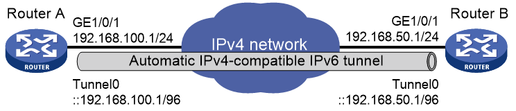
Example: Configuring an automatic IPv4-compatible IPv6 tunnel
Network configuration
As shown in Figure 7, dual-stack routers Router A and Router B communicate over an IPv4 network. Configure an automatic IPv4-compatible IPv6 tunnel between the two routers to enable IPv6 communications over the IPv4 network.
Procedure
Make sure Router A and Router B can reach each other through IPv4.
1. Configure Router A:
# Specify an IPv4 address for GigabitEthernet 1/0/1.
<RouterA> system-view
[RouterA] interface gigabitethernet 1/0/1
[RouterA-GigabitEthernet1/0/1] ip address 192.168.100.1 255.255.255.0
[RouterA-GigabitEthernet1/0/1] quit
# Create an automatic IPv4-compatible IPv6 tunnel.
[RouterA] interface tunnel 0 mode ipv6-ipv4 auto-tunnel
# Specify an IPv4-compatible IPv6 address for the tunnel interface.
[RouterA-Tunnel0] ipv6 address ::192.168.100.1/96
# Specify GigabitEthernet 1/0/1 as the source interface of the tunnel interface.
[RouterA-Tunnel0] source gigabitethernet 1/0/1
2. Configure Router B:
# Specify an IPv4 address for GigabitEthernet 1/0/1.
<RouterB> system-view
[RouterB] interface gigabitethernet 1/0/1
[RouterB-GigabitEthernet1/0/1] ip address 192.168.50.1 255.255.255.0
[RouterB-GigabitEthernet1/0/1] quit
# Create an automatic IPv4-compatible IPv6 tunnel.
[RouterB] interface tunnel 0 mode ipv6-ipv4 auto-tunnel
# Specify an IPv4-compatible IPv6 address for the tunnel interface.
[RouterB-Tunnel0] ipv6 address ::192.168.50.1/96
# Specify GigabitEthernet 1/0/1 as the source interface of the tunnel interface.
[RouterB-Tunnel0] source gigabitethernet 1/0/1
Verifying the configuration
# Use the display ipv6 interface command to display tunnel interface status on Router A and Router B. Verify that the interface tunnel 0 is up. (Details not shown.)
# Verify that Router B and Router A can ping the IPv4-compatible IPv6 address of each other. This example uses Router A.
[RouterA-Tunnel0] ping ipv6 ::192.168.50.1
Ping6(56 data bytes) ::192.168.100.1 --> ::192.168.50.1, press CTRL_C to break
56 bytes from ::192.168.50.1, icmp_seq=0 hlim=64 time=17.000 ms
56 bytes from ::192.168.50.1, icmp_seq=1 hlim=64 time=9.000 ms
56 bytes from ::192.168.50.1, icmp_seq=2 hlim=64 time=11.000 ms
56 bytes from ::192.168.50.1, icmp_seq=3 hlim=64 time=9.000 ms
56 bytes from ::192.168.50.1, icmp_seq=4 hlim=64 time=11.000 ms
--- Ping6 statistics for ::192.168.50.1 ---
5 packet(s) transmitted, 5 packet(s) received, 0.0% packet loss
round-trip min/avg/max/std-dev = 9.000/11.400/17.000/2.939 ms
Configuring a 6to4 tunnel
Restrictions and guidelines
Follow these guidelines when you configure a 6to4 tunnel:
· You do not need to configure a destination address for a 6to4 tunnel, because the destination IPv4 address is embedded in the 6to4 IPv6 address.
· Do not specify the same source addresses for local tunnel interfaces in the same tunnel mode.
· Automatic tunnels do not support dynamic routing. You must configure a static route destined for the destination IPv6 network if the destination IPv6 network is not in the same subnet as the IPv6 address of the tunnel interface. You can specify the local tunnel interface as the egress interface of the route or specify the IPv6 address of the peer tunnel interface as the next hop of the route. For more information about route configuration, see Layer 3—IP Routing Configuration Guide.
Procedure
1. Enter system view.
system-view
2. Enter 6to4 tunnel interface view.
interface tunnel number [ mode ipv6-ipv4 6to4 ]
3. Specify an IPv6 address for the tunnel interface.
See "Configuring basic IPv6 settings."
4. Configure a source address or source interface for the tunnel interface.
source { ipv4-address | interface-type interface-number }
By default, no source address or source interface is configured for the tunnel interface.
If you specify a source address, it is used as the source IP address of tunneled packets.
If you specify a source interface, the primary IP address of this interface is used as the source IP address of tunneled packets.
5. (Optional.) Set the DF bit for tunneled packets.
tunnel dfbit enable
By default, the DF bit is not set for tunneled packets.
Example: Configuring a 6to4 tunnel
Network configuration
As shown in Figure 8, configure a 6to4 tunnel between 6to4 routers Router A and Router B so the two hosts can reach each other over the IPv4 network.
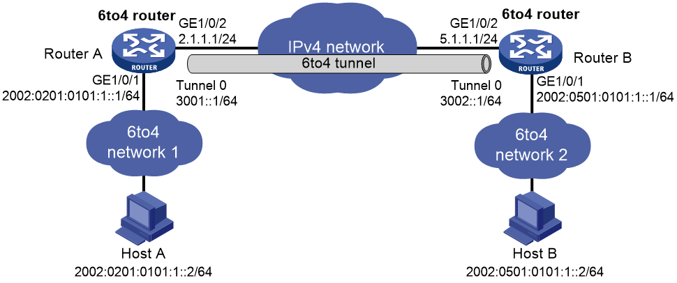
Requirements analysis
To enable communication between 6to4 networks, configure 6to4 addresses for 6to4 routers and hosts in the 6to4 networks.
· The IPv4 address of GigabitEthernet 1/0/2 on Router A is 2.1.1.1/24, and the corresponding 6to4 prefix is 2002:0201:0101::/48. Host A must use this prefix.
· The IPv4 address of GigabitEthernet 1/0/2 on Router B is 5.1.1.1/24, and the corresponding 6to4 prefix is 2002:0501:0101::/48. Host B must use this prefix.
Procedure
Make sure Router A and Router B can reach each other through IPv4.
1. Configure Router A:
# Specify an IPv4 address for GigabitEthernet 1/0/2.
<RouterA> system-view
[RouterA] interface gigabitethernet 1/0/2
[RouterA-GigabitEthernet1/0/2] ip address 2.1.1.1 24
[RouterA-GigabitEthernet1/0/2] quit
# Specify a 6to4 address for GigabitEthernet 1/0/1.
[RouterA] interface gigabitethernet 1/0/1
[RouterA-GigabitEthernet1/0/1] ipv6 address 2002:0201:0101:1::1/64
[RouterA-GigabitEthernet1/0/1] quit
# Create 6to4 tunnel interface Tunnel 0.
[RouterB] interface tunnel 0 mode ipv6-ipv4 6to4
# Specify an IPv6 address for the tunnel interface.
[RouterA-Tunnel0] ipv6 address 3001::1/64
# Specify the source interface as GigabitEthernet 1/0/2 for the tunnel interface.
[RouterA-Tunnel0] source gigabitethernet 1/0/2
[RouterA-Tunnel0] quit
# Configure a static route destined for 2002::/16 through the tunnel interface.
[RouterA] ipv6 route-static 2002:: 16 tunnel 0
2. Configure Router B:
# Specify an IPv4 address for GigabitEthernet 1/0/2.
<RouterB> system-view
[RouterB] interface gigabitethernet 1/0/2
[RouterB-GigabitEthernet1/0/2] ip address 5.1.1.1 24
[RouterB-GigabitEthernet1/0/2] quit
# Specify a 6to4 address for GigabitEthernet 1/0/1.
[RouterB] interface gigabitethernet 1/0/1
[RouterB-GigabitEthernet1/0/1] ipv6 address 2002:0501:0101:1::1/64
[RouterB-GigabitEthernet1/0/1] quit
# Create 6to4 tunnel interface Tunnel 0.
[RouterB] interface tunnel 0 mode ipv6-ipv4 6to4
# Specify an IPv6 address for the tunnel interface.
[RouterB-Tunnel0] ipv6 address 3002::1/64
# Specify the source interface as GigabitEthernet 1/0/2 for the tunnel interface.
[RouterB-Tunnel0] source gigabitethernet 1/0/2
[RouterB-Tunnel0] quit
# Configure a static route destined for 2002::/16 through the tunnel interface.
[RouterB] ipv6 route-static 2002:: 16 tunnel 0
Verifying the configuration
# Verify that Host A and Host B can ping each other.
D:\>ping6 -s 2002:201:101:1::2 2002:501:101:1::2
Pinging 2002:501:101:1::2
from 2002:201:101:1::2 with 32 bytes of data:
Reply from 2002:501:101:1::2: bytes=32 time=13ms
Reply from 2002:501:101:1::2: bytes=32 time=1ms
Reply from 2002:501:101:1::2: bytes=32 time=1ms
Reply from 2002:501:101:1::2: bytes=32 time<1ms
Ping statistics for 2002:501:101:1::2:
Packets: Sent = 4, Received = 4, Lost = 0 (0% loss),
Approximate round trip times in milli-seconds:
Minimum = 0ms, Maximum = 13ms, Average = 3ms
Example: Configuring 6to4 relay
Network configuration
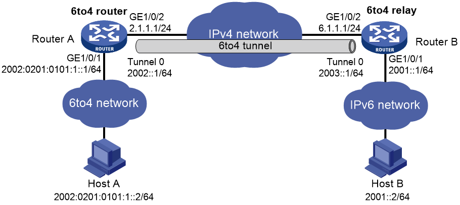
As shown in Figure 9, Router A is a 6to4 router, and 6to4 addresses are used on the connected IPv6 network. Router B acts as a 6to4 relay router and is connected to an IPv6 network (2001::/16). Configure a 6to4 tunnel between Router A and Router B to make Host A and Host B reachable to each other.
The configuration on a 6to4 relay router is similar to that on a 6to4 router. However, to enable communication between the 6to4 network and the IPv6 network, you must configure a route to the IPv6 network on the 6to4 router. The IPv4 address of GigabitEthernet 1/0/2 on the relay router is 6.1.1.1/24 and its corresponding 6to4 prefix is 2002:0601:0101::/48. The next hop of the static route must be an address using this prefix.
Procedure
Make sure Router A and Router B can reach each other through IPv4.
1. Configure Router A:
# Specify an IPv4 address for GigabitEthernet 1/0/2.
<RouterA> system-view
[RouterA] interface gigabitethernet 1/0/2
[RouterA-GigabitEthernet1/0/2] ip address 2.1.1.1 255.255.255.0
[RouterA-GigabitEthernet1/0/2] quit
# Specify a 6to4 address for GigabitEthernet 1/0/1.
[RouterA] interface gigabitethernet 1/0/1
[RouterA-GigabitEthernet1/0/1] ipv6 address 2002:0201:0101:1::1/64
[RouterA-GigabitEthernet1/0/1] quit
# Create 6to4 tunnel interface Tunnel 0.
[RouterA] interface tunnel 0 mode ipv6-ipv4 6to4
# Specify an IPv6 address for the tunnel interface.
[RouterA-Tunnel0] ipv6 address 2002::1/64
# Specify GigabitEthernet 1/0/2 as the source interface of the tunnel interface.
[RouterA-Tunnel0] source gigabitethernet 1/0/2
[RouterA-Tunnel0] quit
# Configure a static route to the 6to4 relay router.
[RouterA] ipv6 route-static 2002:0601:0101:: 64 tunnel 0
# Configure a default route to reach the IPv6 network, which specifies the next hop as the 6to4 address of the relay router.
[RouterA] ipv6 route-static :: 0 2002:0601:0101::1
2. Configure Router B:
# Specify an IPv4 address for GigabitEthernet 1/0/2.
<RouterB> system-view
[RouterB] interface gigabitethernet 1/0/2
[RouterB-GigabitEthernet1/0/2] ip address 6.1.1.1 255.255.255.0
[RouterB-GigabitEthernet1/0/2] quit
# Specify an IPv6 address for GigabitEthernet 1/0/1.
[RouterB] interface gigabitethernet 1/0/1
[RouterB-GigabitEthernet1/0/1] ipv6 address 2001::1/16
[RouterB-GigabitEthernet1/0/1] quit
# Create 6to4 tunnel interface Tunnel 0.
[RouterB] interface tunnel 0 mode ipv6-ipv4 6to4
# Specify an IPv6 address for the tunnel interface.
[RouterB-Tunnel0] ipv6 address 2003::1/64
# Specify GigabitEthernet 1/0/2 as the source interface of the tunnel interface.
[RouterB-Tunnel0] source gigabitethernet 1/0/2
[RouterB-Tunnel0] quit
# Configure a static route destined for 2002::/16 through the tunnel interface.
[RouterB] ipv6 route-static 2002:: 16 tunnel 0
Verifying the configuration
# Verify that Host A and Host B can ping each other.
D:\>ping6 -s 2002:201:101:1::2 2001::2
Pinging 2001::2
from 2002:201:101:1::2 with 32 bytes of data:
Reply from 2001::2: bytes=32 time=13ms
Reply from 2001::2: bytes=32 time=1ms
Reply from 2001::2: bytes=32 time=1ms
Reply from 2001::2: bytes=32 time<1ms
Ping statistics for 2001::2:
Packets: Sent = 4, Received = 4, Lost = 0 (0% loss),
Approximate round trip times in milli-seconds:
Minimum = 0ms, Maximum = 13ms, Average = 3ms
Configuring an ISATAP tunnel
Restrictions and guidelines
Follow these guidelines when you configure an ISATAP tunnel:
· You do not need to configure a destination address for an ISATAP tunnel, because the destination IPv4 address is embedded in the ISATAP address.
· Do not specify the same source addresses for local tunnel interfaces in the same tunnel mode.
· Because automatic tunnels do not support dynamic routing, configure a static route destined for the destination IPv6 network at each tunnel end. You can specify the local tunnel interface as the egress interface of the route or specify the IPv6 address of the peer tunnel interface as the next hop of the route. For more information about route configuration, see Layer 3—IP Routing Configuration Guide.
Procedure
1. Enter system view.
system-view
2. Enter ISATAP tunnel interface view.
interface tunnel number [ mode ipv6-ipv4 isatap ]
3. Specify an IPv6 address for the tunnel interface.
See "Configuring basic IPv6 settings."
4. Configure a source address or source interface for the tunnel interface.
source { ipv4-address | interface-type interface-number }
By default, no source address or source interface is configured for the tunnel interface.
If you specify a source address, it is used as the source IP address of tunneled packets.
If you specify a source interface, the primary IP address of this interface is used as the source IP address of tunneled packets.
5. (Optional.) Set the DF bit for tunneled packets.
tunnel dfbit enable
By default, the DF bit is not set for tunneled packets.
Example: Configuring an ISATAP tunnel
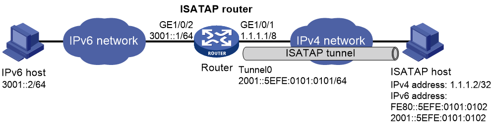
Network configuration
As shown in Figure 10, configure an ISATAP tunnel between the router and the ISATAP host so the ISATAP host in the IPv4 network can access the IPv6 network.
Procedure
1. Configure the router:
# Specify an IPv6 address for GigabitEthernet 1/0/2.
<Router> system-view
[Router] interface gigabitethernet 1/0/2
[Router-GigabitEthernet1/0/2] ipv6 address 3001::1/64
[Router-GigabitEthernet1/0/2] quit
# Specify an IPv4 address for GigabitEthernet 1/0/1.
[Router] interface gigabitethernet 1/0/1
[Router-GigabitEthernet1/0/1] ip address 1.1.1.1 255.0.0.0
[Router-GigabitEthernet1/0/1] quit
# Create ISATAP tunnel interface Tunnel 0.
[Router] interface tunnel 0 mode ipv6-ipv4 isatap
# Specify an EUI-64 IPv6 address for the tunnel interface.
[Router-Tunnel0] ipv6 address 2001:: 64 eui-64
# Specify GigabitEthernet 1/0/1 as the source interface of the tunnel interface.
[Router-Tunnel0] source gigabitethernet 1/0/1
# Disable RA suppression so that the ISATAP host can acquire information such as the address prefix from the RA message advertised by the ISATAP router.
[Router-Tunnel0] undo ipv6 nd ra halt
[Router-Tunnel0] quit
2. Configure the ISATAP host:
Configurations on the ISATAP host vary by operating system. The following configuration is performed on Windows XP.
# Install IPv6.
C:\>ipv6 install
# On a host running Windows XP, the ISATAP interface is typically interface 2. Display information about the ISATAP interface.
C:\>ipv6 if 2
Interface 2: Automatic Tunneling Pseudo-Interface
Guid {48FCE3FC-EC30-E50E-F1A7-71172AEEE3AE}
does not use Neighbor Discovery
does not use Router Discovery
routing preference 1
EUI-64 embedded IPv4 address: 0.0.0.0
router link-layer address: 0.0.0.0
preferred link-local fe80::5efe:1.1.1.2, life infinite
link MTU 1280 (true link MTU 65515)
current hop limit 128
reachable time 42500ms (base 30000ms)
retransmission interval 1000ms
DAD transmits 0
default site prefix length 48
# Specify an IPv4 address for the ISATAP router.
C:\>netsh interface ipv6 isatap set router 1.1.1.1
# Display information about the ISATAP interface.
C:\>ipv6 if 2
Interface 2: Automatic Tunneling Pseudo-Interface
Guid {48FCE3FC-EC30-E50E-F1A7-71172AEEE3AE}
does not use Neighbor Discovery
uses Router Discovery
routing preference 1
EUI-64 embedded IPv4 address: 1.1.1.2
router link-layer address: 1.1.1.1
preferred global 2001::5efe:1.1.1.2, life 29d23h59m46s/6d23h59m46s (public)
preferred link-local fe80::5efe:1.1.1.2, life infinite
link MTU 1500 (true link MTU 65515)
current hop limit 255
reachable time 42500ms (base 30000ms)
retransmission interval 1000ms
DAD transmits 0
default site prefix length 48
The host has obtained the prefix 2001::/64 and has automatically generated the global unicast address 2001::5efe:1.1.1.2. The message "uses Router Discovery" indicates that the router discovery feature is enabled on the host.
# Display information about IPv6 routes on the host.
C:\>ipv6 rt
2001::/64 -> 2 pref 1if+8=9 life 29d23h59m43s (autoconf)
::/0 -> 2/fe80::5efe:1.1.1.1 pref 1if+256=257 life 29m43s (autoconf)
3. On the IPv6 host, configure a route to the ISATAP router.
C:\>netsh interface ipv6 set route 2001::/64 5 3001::1
Verifying the configuration
# Verify that the ISATAP host can ping the IPv6 host.
C:\>ping 3001::2
Pinging 3001::2 with 32 bytes of data:
Reply from 3001::2: time=1ms
Reply from 3001::2: time=1ms
Reply from 3001::2: time=1ms
Reply from 3001::2: time=1ms
Ping statistics for 3001::2:
Packets: Sent = 4, Received = 4, Lost = 0 (0% loss),
Approximate round trip times in milli-seconds:
Minimum = 1ms, Maximum = 1ms, Average = 1ms
Configuring a 6RD tunnel
Restrictions and guidelines
Follow these guidelines when you configure a 6RD tunnel:
· You do not need to configure a destination address for a 6RD tunnel. The device automatically identifies the destination IPv4 address according to the IPv4 address embedded in the 6RD address, the 6RD prefix, and the IPv4 prefix and suffix.
· Do not specify the same source addresses for local tunnel interfaces in the same tunnel mode.
· Automatic tunnels do not support dynamic routing. You must configure a static route destined for the destination IPv6 network if the destination IPv6 network is not in the same subnet as the IPv6 address of the tunnel interface. You can specify the local tunnel interface as the egress interface of the route or specify the IPv6 address of the peer tunnel interface as the next hop of the route. For more information about route configuration, see Layer 3—IP Routing Configuration Guide.
Procedure
1. Enter system view.
system-view
2. Enter 6RD tunnel interface view.
interface tunnel number mode ipv6-ipv4 6rd
3. Specify an IPv6 address for the tunnel interface.
See "Configuring basic IPv6 settings."
4. Configure a source address or source interface for the tunnel interface.
source { ipv4-address | interface-type interface-number }
By default, no source address or source interface is configured for the tunnel interface.
If you specify a source address, it is used as the source IP address of tunneled packets.
If you specify a source interface, the primary IP address of this interface is used as the source IP address of tunneled packets.
5. Configure the 6RD prefix for the tunnel.
tunnel 6rd prefix ipv6-prefix/prefix-length
By default, no 6RD prefix is configured for the tunnel.
6. (Optional.) Specify a prefix length and suffix length for the tunnel source address.
tunnel 6rd ipv4 { prefix-length length | suffix-length length } *
By default, all 32 bits of the IPv4 tunnel source address are used to create the 6RD delegated prefix.
7. (Optional.) Specify a BR address for the tunnel.
tunnel 6rd br ipv4-address
By default, no BR address is specified for a 6RD tunnel.
8. (Optional.) Set the DF bit for tunneled packets.
tunnel dfbit enable
By default, the DF bit is not set for tunneled packets.
Display and maintenance commands for 6RD tunneling
Execute display commands in any view.
|
Task |
Command |
|
Display information about 6RD tunnel interfaces. |
display 6rd [ interface tunnel number ] |
|
Display a 6RD tunnel destination address. |
display 6rd destination prefix ipv6-prefix interface tunnel number |
|
Display a 6RD delegated prefix. |
display 6rd prefix destination ipv4-address interface tunnel number |
Example: Configuring a 6RD tunnel
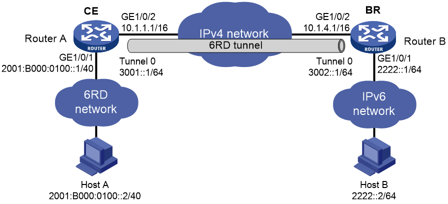
Network configuration
As shown in Figure 11, Host A and Host B are in different 6RD networks. Configure a 6RD tunnel between Router A and Router B so Host A and Host B can reach each other over the IPv4 network.
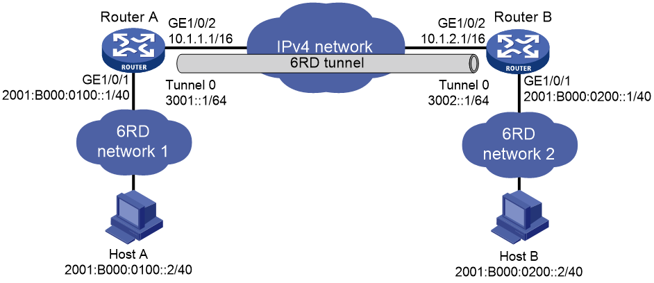
Requirements analysis
To enable communication between 6RD networks, you must perform the following tasks in addition to the 6RD tunnel configuration:
· On Router A and Router B, configure the 6RD prefix as 2001:B000::/32, the IPv4 prefix length as 16, and the IPv4 suffix length as 8.
· Configure 6RD addresses for the routers and hosts.
¡ On Router A, the tunnel source IPv4 address is 10.1.1.1/16, the IPv4 address of GigabitEthernet 1/0/2. Calculated based on this IPv4 address, the 6RD prefix, and the IPv4 prefix and suffix lengths, the 6RD delegated prefix for 6RD network 1 is 2001:B000:100::/40. The 6RD addresses of Router A and Host A must use this prefix.
¡ On Router B, the tunnel source IPv4 address is 10.1.2.1/16, the IPv4 address of GigabitEthernet 1/0/2. Calculated based on this IPv4 address, the 6RD prefix, and the IPv4 prefix and suffix lengths, the 6RD delegated prefix for 6RD network 2 is 2001:B000:200::/40. The 6RD addresses of Router B and Host B must use this prefix.
Procedure
Make sure Router A and Router B can reach each other through IPv4.
1. Configure Router A:
# Specify an IPv4 address for GigabitEthernet 1/0/2.
<RouterA> system-view
[RouterA] interface gigabitethernet 1/0/2
[RouterA-GigabitEthernet1/0/2] ip address 10.1.1.1 16
[RouterA-GigabitEthernet1/0/2] quit
# Specify a 6RD address for GigabitEthernet 1/0/1.
[RouterA] interface gigabitethernet 1/0/1
[RouterA-GigabitEthernet1/0/1] ipv6 address 2001:b000:0100::1/40
[RouterA-GigabitEthernet1/0/1] quit
# Create 6RD tunnel interface Tunnel 0.
[RouterA] interface tunnel 0 mode ipv6-ipv4 6rd
# Specify an IPv6 address for the tunnel interface.
[RouterA-Tunnel0] ipv6 address 3001::1/64
# Specify the source interface as GigabitEthernet 1/0/2 for the tunnel interface.
[RouterA-Tunnel0] source gigabitethernet 1/0/2
# Configure the 6RD prefix for the tunnel interface.
[RouterA-Tunnel0] tunnel 6rd prefix 2001:b000::/32
# Specify a prefix length and a suffix length for the tunnel interface.
[RouterA-Tunnel0] tunnel 6rd ipv4 prefix-len 16 suffix-len 8
[RouterA-Tunnel0] quit
# Configure a static route destined for 2001:B000::/32 through the tunnel interface.
[RouterA] ipv6 route-static 2001:b000:: 32 tunnel 0
2. Configure Router B:
# Specify an IPv4 address for GigabitEthernet 1/0/2.
<RouterB> system-view
[RouterB] interface gigabitethernet 1/0/2
[RouterB-GigabitEthernet1/0/2] ip address 10.1.2.1 16
[RouterB-GigabitEthernet1/0/2] quit
# Specify a 6RD address for GigabitEthernet 1/0/1.
[RouterB] interface gigabitethernet 1/0/1
[RouterB-GigabitEthernet1/0/1] ipv6 address 2001:b000:0200::1/40
[RouterB-GigabitEthernet1/0/1] quit
# Create 6RD tunnel interface Tunnel 0.
[RouterB] interface tunnel 0 mode ipv6-ipv4 6rd
# Specify an IPv6 address for the tunnel interface.
[RouterB-Tunnel0] ipv6 address 3002::1/64
# Specify the source interface as GigabitEthernet 1/0/2 for the tunnel interface.
[RouterB-Tunnel0] source gigabitethernet 1/0/2
# Configure the 6RD prefix for the tunnel interface.
[RouterB-Tunnel0] tunnel 6rd prefix 2001:b000::/32
# Specify a prefix length and a suffix length for the tunnel interface.
[RouterB-Tunnel0] tunnel 6rd ipv4 prefix-len 16 suffix-len 8
[RouterB-Tunnel0] quit
# Configure a static route destined for 2001:B000::/32 through the tunnel interface.
[RouterB] ipv6 route-static 2001:b000:: 32 tunnel 0
Verifying the configuration
# Verify that Host A and Host B can ping each other.
D:\>ping6 -s 2001:b000:0100::2 2001:b000:0200::2
Pinging 2001:B000:0200::2
from 2001:B000:0100::2 with 32 bytes of data:
Reply from 2001:B000:0200::2: bytes=32 time=13ms
Reply from 2001:B000:0200::2: bytes=32 time=1ms
Reply from 2001:B000:0200::2: bytes=32 time=1ms
Reply from 2001:B000:0200::2: bytes=32 time<1ms
Ping statistics for 2001:B000:0200::2:
Packets: Sent = 4, Received = 4, Lost = 0 (0% loss),
Approximate round trip times in milli-seconds:
Minimum = 0ms, Maximum = 13ms, Average = 3ms
Example: Configuring 6RD relay
Network configuration
As shown in Figure 12, Host A is in a 6RD network connected to Router A (a 6RD CE). Host B is in a common IPv6 network connected to Router B (a 6RD BR router). Configure a 6RD tunnel between Router A and Router B to make Host A and Host B reachable to each other.
Requirements analysis
To enable communication between the 6RD network and the IPv6 network, you must perform the following tasks in addition to the 6RD tunnel configuration:
· On Router A and Router B, configure the 6RD prefix as 2001:B000::/32, the IPv4 prefix length as 16, and the IPv4 suffix length as 8.
· Configure 6RD addresses for Router A and Host A in the 6RD network.
On Router A, the tunnel source IPv4 address is 10.1.1.1/16, the IPv4 address of GigabitEthernet 1/0/2. Calculated based on this IPv4 address, the 6RD prefix, and the IPv4 prefix and suffix lengths, the 6RD delegated prefix for 6RD network 1 is 2001:B000:100::/40. The 6RD addresses of Router A and Host A must use this prefix.
· On Router A, you must configure a static route to the IPv6 network. The next hop address of the route is a 6RD address of Router B.
On Router B, the tunnel source IPv4 address is 10.1.4.1/16, the IPv4 address of GigabitEthernet 1/0/2. Calculated based on this IPv4 address, the 6RD prefix, and the IPv4 prefix and suffix lengths, the 6RD delegated prefix is 2001:B000:0400::/40. The next hop address of the static route can be any address using this prefix.
Procedure
Make sure Router A and Router B can reach each other through IPv4.
1. Configure Router A:
# Specify an IPv4 address for GigabitEthernet 1/0/2.
<RouterA> system-view
[RouterA] interface gigabitethernet 1/0/2
[RouterA-GigabitEthernet1/0/2] ip address 10.1.1.1 16
[RouterA-GigabitEthernet1/0/2] quit
# Specify a 6RD address for GigabitEthernet 1/0/1.
[RouterA] interface gigabitethernet 1/0/1
[RouterA-GigabitEthernet1/0/1] ipv6 address 2001:b000:0100::1/40
[RouterA-GigabitEthernet1/0/1] quit
# Create 6RD tunnel interface Tunnel 0.
[RouterA] interface tunnel 0 mode ipv6-ipv4 6rd
# Specify an IPv6 address for the tunnel interface.
[RouterA-Tunnel0] ipv6 address 3001::1/64
# Specify the source interface as GigabitEthernet 1/0/2 for the tunnel interface.
[RouterA-Tunnel0] source gigabitethernet 1/0/2
# Configure the 6RD prefix for the tunnel interface.
[RouterA-Tunnel0] tunnel 6rd prefix 2001:b000::/32
# Specify a prefix length and a suffix length for the tunnel interface.
[RouterA-Tunnel0] tunnel 6rd ipv4 prefix-len 16 suffix-len 8
# Specify the BR address on the tunnel interface.
[RouterA-Tunnel0] tunnel 6rd br 10.1.4.1
[RouterA-Tunnel0] quit
# Configure a default route to reach the IPv6 network, which specifies the next hop as the 6RD address of Router B.
[RouterA] ipv6 route-static :: 0 2001:b000:0400::1
# Configure a static route destined for 2001:B000::/32 through the tunnel interface.
[RouterA] ipv6 route-static 2001:b000:: 32 tunnel 0
2. Configure Router B:
# Specify an IPv4 address for GigabitEthernet 1/0/2.
<RouterB> system-view
[RouterB] interface gigabitethernet 1/0/2
[RouterB-GigabitEthernet1/0/2] ip address 10.1.4.1 16
[RouterB-GigabitEthernet1/0/2] quit
# Specify an IPv6 address for GigabitEthernet 1/0/1.
[RouterB] interface gigabitethernet 1/0/1
[RouterB-GigabitEthernet1/0/1] ipv6 address 2222::1/64
[RouterB-GigabitEthernet1/0/1] quit
# Create 6RD tunnel interface Tunnel 0.
[RouterB] interface tunnel 0 mode ipv6-ipv4 6rd
# Specify an IPv6 address for the tunnel interface.
[RouterB-Tunnel0] ipv6 address 3002::1/64
# Specify the source interface as GigabitEthernet 1/0/2 for the tunnel interface.
[RouterB-Tunnel0] source gigabitethernet 1/0/2
# Configure the 6RD prefix for the tunnel interface.
[RouterB-Tunnel0] tunnel 6rd prefix 2001:b000::/32
# Specify a prefix length and a suffix length for the tunnel interface.
[RouterB-Tunnel0] tunnel 6rd ipv4 prefix-len 16 suffix-len 8
[RouterB-Tunnel0] quit
# Configure a static route destined for 2001:B000::/32 through the tunnel interface.
[RouterB] ipv6 route-static 2001:b000:: 32 tunnel 0
Verifying the configuration
# Verify that Host A and Host B can ping each other.
D:\>ping6 -s 2001:b000:0100::2 2222::2
Pinging 2001::2
from 2001:B000:0100::2 with 32 bytes of data:
Reply from 2222::2: bytes=32 time=13ms
Reply from 2222::2: bytes=32 time=1ms
Reply from 2222::2: bytes=32 time=1ms
Reply from 2222::2: bytes=32 time<1ms
Ping statistics for 2222::2:
Packets: Sent = 4, Received = 4, Lost = 0 (0% loss),
Approximate round trip times in milli-seconds:
Minimum = 0ms, Maximum = 13ms, Average = 3ms
Enabling dropping IPv6 packets that use IPv4-compatible IPv6 addresses
Restrictions and guidelines
Automatic IPv4-compatible IPv6 tunnels do not support this feature.
Procedure
1. Enter system view.
system-view
2. Enable dropping IPv6 packets that use IPv4-compatible IPv6 addresses.
tunnel discard ipv4-compatible-packet
By default, IPv6 packets that use IPv4-compatible IPv6 addresses are not dropped.
IPv4 over IPv4 tunneling
About IPv4 over IPv4 tunneling
IPv4 over IPv4 tunneling (RFC 1853) enables isolated IPv4 networks to communicate. For example, an IPv4 over IPv4 tunnel can connect isolated private IPv4 networks over a public IPv4 network.
Figure 13 IPv4 over IPv4 tunnel

Figure 13 shows the encapsulation and de-encapsulation processes.
· Encapsulation:
a. Device A receives an IP packet from an IPv4 host and submits it to the IP protocol stack.
b. The IPv4 protocol stack determines how to forward the packet according to the destination address in the IP header. If the packet is destined for the IPv4 host connected to Device B, Device A delivers the packet to the tunnel interface.
c. The tunnel interface adds a new IPv4 header to the IPv4 packet and submits it to the IP protocol stack.
In the new header, the source IP address specifies the tunnel source, and the destination IP address specifies the tunnel destination.
d. The IP protocol stack uses the destination IP address of the new IP header to look up the routing table, and then sends the packet out.
· De-encapsulation:
a. After receiving the packet, Device B delivers it to the IP protocol stack.
b. If the protocol number is 4 (indicating an IPv4 packet is encapsulated within the packet), the IP protocol stack delivers the packet to the tunnel module for de-encapsulation.
c. The tunnel module de-encapsulates the IP packet and sends it back to the IP protocol stack.
d. The protocol stack forwards the de-encapsulated packet.
Restrictions and guidelines: IPv4 over IPv4 tunnel configuration
Follow these guidelines when you configure an IPv4 over IPv4 tunnel:
· The tunnel destination address specified on the local device must be identical with the tunnel source address specified on the tunnel peer device.
· Do not specify the same source and destination addresses for local tunnel interfaces in the same tunnel mode.
· The IPv4 address of the local tunnel interface cannot be on the same subnet as the destination address configured on the tunnel interface.
· To ensure correct packet forwarding, identify whether the destination IPv4 network and the IPv4 address of the local tunnel interface are on the same subnet. If they are not, configure a route reaching the destination IPv4 network through the tunnel interface. You can configure the route by using one of the following methods:
¡ Configure a static route, and specify the local tunnel interface as the egress interface or specify the IPv4 address of the peer tunnel interface as the next hop.
¡ Enable a dynamic routing protocol on both the local and remote tunnel interfaces.
For more information about route configuration, see Layer 3—IP Routing Configuration Guide.
· The destination address of the route passing the tunnel interface cannot be on the same subnet as the destination address configured on the tunnel interface.
Configuring an IPv4 over IPv4 tunnel
1. Enter system view.
system-view
2. Enter IPv4 over IPv4 tunnel interface view.
interface tunnel number [ mode ipv4-ipv4 ]
3. Configure an IPv4 address for the tunnel interface.
ip address ip-address { mask | mask-length } [ sub ]
4. Configure a source address or source interface for the tunnel interface.
source { ipv4-address | interface-type interface-number }
By default, no source address or source interface is configured for the tunnel interface.
If you specify a source address, it is used as the source IP address of tunneled packets.
If you specify a source interface, the primary IP address of this interface is used as the source IP address of tunneled packets.
5. Configure a destination address for the tunnel interface.
destination ipv4-address
By default, no destination address is configured for the tunnel interface.
The tunnel destination address must be the IP address of the receiving interface on the tunnel peer. It is used as the destination IP address of tunneled packets.
6. (Optional.) Set the DF bit for tunneled packets.
tunnel dfbit enable
By default, the DF bit is not set for tunneled packets.
IPv4 over IPv4 tunnel configuration examples
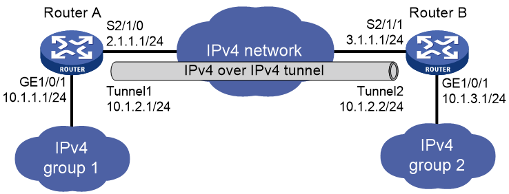
Example: Configuring an IPv4 over IPv4 tunnel
Network configuration
As shown in Figure 14, the two subnets IPv4 group 1 and IPv4 group 2 use private IPv4 addresses. Configure an IPv4 over IPv4 tunnel between Router A and Router B to make the two subnets reachable to each other.
Procedure
Make sure Router A and Router B can reach each other through IPv4.
1. Configure Router A:
# Specify an IPv4 address for GigabitEthernet 1/0/1.
<RouterA> system-view
[RouterA] interface gigabitethernet 1/0/1
[RouterA-GigabitEthernet1/0/1] ip address 10.1.1.1 255.255.255.0
[RouterA-GigabitEthernet1/0/1] quit
# Specify an IPv4 address for Serial 2/1/0, which is the physical interface of the tunnel.
[RouterA] interface serial 2/1/0
[RouterA-Serial2/1/0] ip address 2.1.1.1 255.255.255.0
[RouterA-Serial2/1/0] quit
# Create IPv4 over IPv4 tunnel interface Tunnel 1.
[RouterA] interface tunnel 1 mode ipv4-ipv4
# Specify an IPv4 address for the tunnel interface.
[RouterA-Tunnel1] ip address 10.1.2.1 255.255.255.0
# Specify the IP address of Serial 2/1/0 as the source address for the tunnel interface.
[RouterA-Tunnel1] source 2.1.1.1
# Specify the IP address of Serial 2/1/1 on Router B as the destination address for the tunnel interface.
[RouterA-Tunnel1] destination 3.1.1.1
[RouterA-Tunnel1] quit
# Configure a static route destined for IPv4 group 2 through the tunnel interface.
[RouterA] ip route-static 10.1.3.0 255.255.255.0 tunnel 1
2. Configure Router B:
# Specify an IPv4 address for GigabitEthernet 1/0/1.
<RouterB> system-view
[RouterB] interface gigabitethernet 1/0/1
[RouterB-GigabitEthernet1/0/1] ip address 10.1.3.1 255.255.255.0
[RouterB-GigabitEthernet1/0/1] quit
# Specify an IPv4 address for Serial 2/1/1, which is the physical interface of the tunnel.
[RouterB] interface serial 2/1/1
[RouterB-Serial2/1/1] ip address 3.1.1.1 255.255.255.0
[RouterB-Serial2/1/1] quit
# Create IPv4 over IPv4 tunnel interface Tunnel 2.
[RouterB] interface tunnel 2 mode ipv4-ipv4
# Specify an IPv4 address for the tunnel interface.
[RouterB-Tunnel2] ip address 10.1.2.2 255.255.255.0
# Specify the IP address of Serial 2/1/1 as the source address for the tunnel interface.
[RouterB-Tunnel2] source 3.1.1.1
# Specify the IP address of Serial 2/1/0 on Router A as a destination address for the tunnel interface.
[RouterB-Tunnel2] destination 2.1.1.1
[RouterB-Tunnel2] quit
# Configure a static route destined for IPv4 group 1 through the tunnel interface.
[RouterB] ip route-static 10.1.1.0 255.255.255.0 tunnel 2
Verifying the configuration
# Use the display interface tunnel command to display the status of the tunnel interfaces on Router A and Router B. Verify that the tunnel interfaces are up. (Details not shown.)
# Verify that Router A and Router B can ping the IPv4 address of the peer interface GigabitEthernet 1/0/1. This example uses Router A.
[RouterA] ping -a 10.1.1.1 10.1.3.1
Ping 10.1.3.1 (10.1.3.1) from 10.1.1.1: 56 data bytes, press CTRL_C to break
56 bytes from 10.1.3.1: icmp_seq=0 ttl=255 time=2.000 ms
56 bytes from 10.1.3.1: icmp_seq=1 ttl=255 time=1.000 ms
56 bytes from 10.1.3.1: icmp_seq=2 ttl=255 time=0.000 ms
56 bytes from 10.1.3.1: icmp_seq=3 ttl=255 time=1.000 ms
56 bytes from 10.1.3.1: icmp_seq=4 ttl=255 time=1.000 ms
--- Ping statistics for 10.1.3.1 ---
5 packet(s) transmitted, 5 packet(s) received, 0.0% packet loss
round-trip min/avg/max/std-dev = 0.000/1.000/2.000/0.632 ms
IPv4 over IPv6 tunneling
About IPv4 over IPv6 tunneling
Implementation
IPv4 over IPv6 tunneling adds an IPv6 header to IPv4 packets so that the IPv4 packets can pass an IPv6 network through a tunnel to realize interworking between isolated IPv4 networks.
Figure 15 IPv4 over IPv6 tunnel

Figure 15 shows the encapsulation and de-encapsulation processes.
· Encapsulation:
a. Upon receiving an IPv4 packet, Device A delivers it to the IPv4 protocol stack.
b. The IPv4 protocol stack uses the destination address of the packet to determine the egress interface. If the egress interface is the tunnel interface, the IPv4 protocol stack delivers the packet to the tunnel interface.
c. The tunnel interface adds an IPv6 header to the original IPv4 packet and delivers the packet to the IPv6 protocol stack.
d. The IPv6 protocol stack uses the destination IPv6 address of the packet to look up the routing table, and then sends it out.
· De-encapsulation:
a. Upon receiving the IPv6 packet from the attached IPv6 network, Device B delivers the packet to the IPv6 protocol stack to examine the protocol type encapsulated in the data portion of the packet.
b. If the protocol type is IPv4, the IPv6 protocol stack delivers the packet to the tunneling module.
c. The tunneling module removes the IPv6 header and delivers the remaining IPv4 packet to the IPv4 protocol stack.
d. The IPv4 protocol stack forwards the IPv4 packet.
Tunnel modes
IPv4 over IPv6 tunnels include IPv4 over IPv6 manual tunnels and DS-Lite tunnels.
IPv4 over IPv6 manual tunnel
An IPv4 over IPv6 manual tunnel is a point-to-point link and its source and destination IPv6 addresses are manually configured. You can establish an IPv4 over IPv6 manual tunnel to connect isolated IPv4 networks over an IPv6 network.
DS-Lite tunnel
Dual Stack Lite (DS-Lite) is a combination of the tunneling and NAT technologies. NAT translates the private IPv4 addresses of the IPv4 hosts before the hosts reach the IPv4 public network.
DS-Lite tunnel supports only an IPv4 host in a private network initiating communication with an IPv4 host on the Internet. It does not support an IPv4 host on the Internet initiating communication with an IPv4 host in a private network.
Figure 16 DS-Lite tunnel
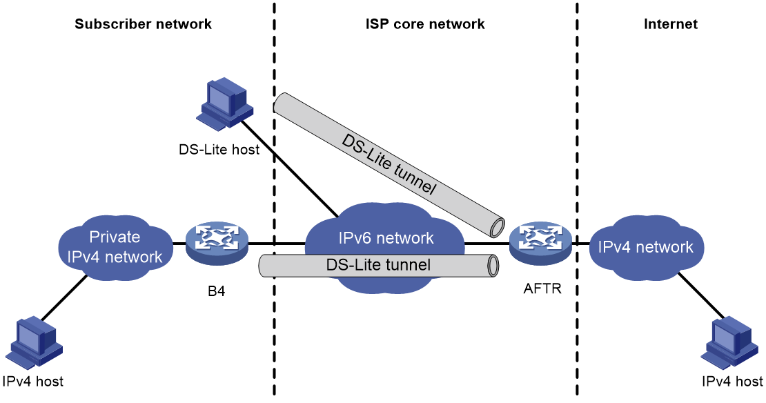
As shown in Figure 16, the DS-Lite feature contains the following components:
· Basic Bridging BroadBand (B4) element
The B4 element is typically a CPE router that connects end hosts. IPv4 packets entering the B4 router are encapsulated into IPv6 packets and sent to the AFTR. IPv6 packets from the AFTR are de-encapsulated into IPv4 packets and sent to the subscriber's network.
Hosts that can act as the B4 router are referred to as DS-Lite hosts.
· Address Family Transition Router (AFTR)
An AFTR resides in the ISP network and terminates the tunnel from the B4 router. NAT is also implemented on the interface that is connected to the public IPv4 network.
An AFTR de-encapsulates the tunneled packet, translates the network address, and routes the packet to the destination IPv4 network. For IPv4 packets coming from the public IPv4 network, the AFTR performs reverse address translation and sends them to the B4 router by using the DS-Lite tunnel.
Figure 17 Packet forwarding process in DS-Lite
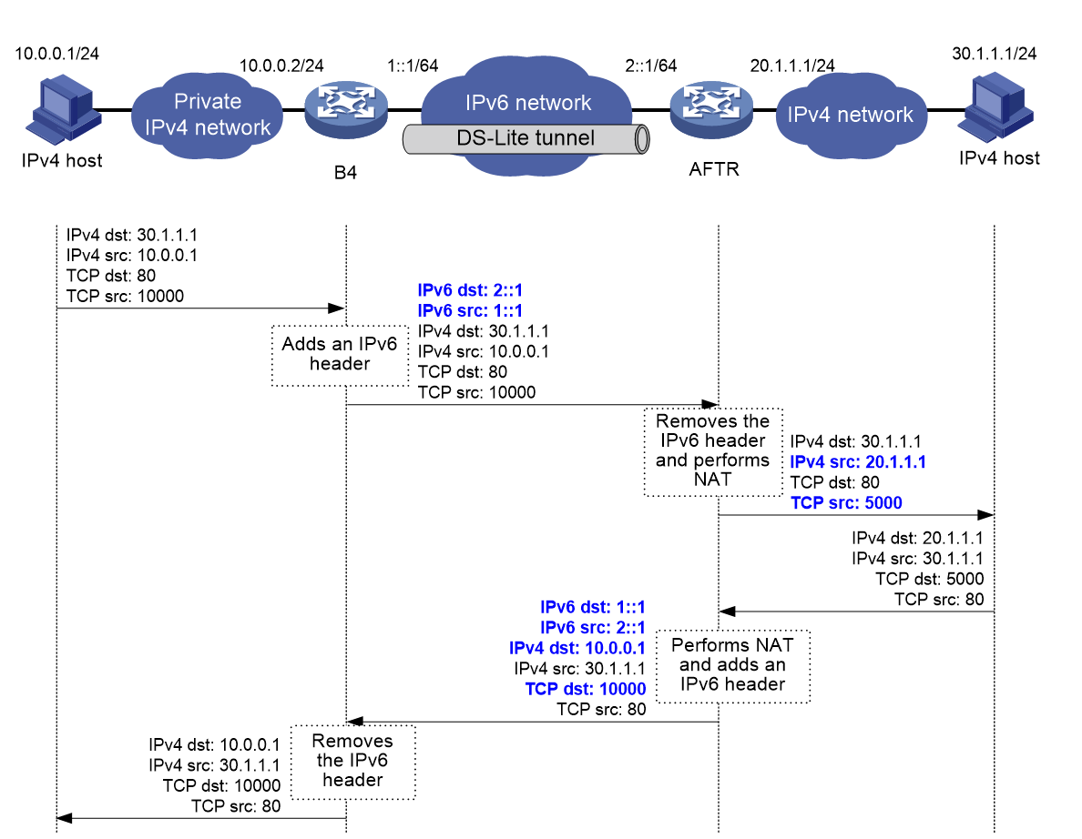
As shown in Figure 17, the packet forwarding process in DS-Lite is as follows:
1. Upon receiving a packet from the private IPv4 network, the B4 router adds an IPv6 header to the packet and sends the IPv6 packet to the AFTR through the tunnel.
2. The AFTR performs the following operations:
a. Removes the IPv6 header from the tunneled packet.
b. Assigns a tunnel ID for the B4 router.
c. Records the mapping between the IPv6 address of the B4 router (the source IPv6 address of the packet), and the tunnel ID.
3. After de-encapsulation, the AFTR translates the source private IPv4 address of the packet into a public IPv4 address and sends the packet to the destination IPv4 host. The AFTR also maps the NAT entries to the tunnel ID so that IPv4 networks connected to different B4 routers can use the same address space.
4. Upon receiving the response packet from the public network, the AFTR translates the destination public IPv4 address into the private IPv4 address. The AFTR performs the following operations:
a. Looks up the IPv6 address-tunnel ID mapping to obtain the IP address of the B4 router.
b. Uses the address as the destination address of the encapsulated IPv6 packet.
c. Forwards the packet to the B4 router.
Figure 17 shows an example of PAT translation for dynamic NAT. Typically, dynamic NAT is used. When you use static NAT for DS-Lite tunneling, make sure the IP addresses of private IPv4 networks connected to different B4 routers do not overlap. For more information about NAT, see "Configuring NAT."
Configuring an IPv4 over IPv6 manual tunnel
Restrictions and guidelines
When you perform the tasks in this section, follow these restrictions and guidelines:
· The tunnel destination address specified on the local device must be identical with the tunnel source address specified on the tunnel peer device.
· Do not specify the same source and destination addresses for local tunnel interfaces in the same tunnel mode.
· To ensure correct packet forwarding, identify whether the destination IPv4 network and the IPv4 address of the local tunnel interface are on the same subnet. If they are not, configure a route reaching the destination IPv4 network through the tunnel interface. You can configure the route by using one of the following methods:
¡ Configure a static route, and specify the local tunnel interface as the egress interface or specify the IPv6 address of the peer tunnel interface as the next hop.
¡ Enable a dynamic routing protocol on both the local and remote tunnel interfaces.
For more information about route configuration, see Layer 3—IP Routing Configuration Guide.
Procedure
1. Enter system view.
system-view
2. Enter IPv6 tunnel interface view.
interface tunnel number [ mode ipv6 ]
3. Configure an IPv4 address for the tunnel interface.
ip address ip-address { mask | mask-length } [ sub ]
4. Configure the source address or interface for the tunnel interface.
source { ipv6-address | interface-type interface-number }
By default, no source address or interface is configured for the tunnel.
If you specify a source address, it is used as the source IPv6 address of tunneled packets.
If you specify a source interface, the lowest IPv6 address of this interface is used as the source IPv6 address of tunneled packets.
5. Configure the destination address for the tunnel interface.
destination ipv6-address
By default, no destination address is configured for the tunnel.
The tunnel destination address must be the IPv6 address of the receiving interface on the tunnel peer. It is used as the destination IPv6 address of tunneled packets.
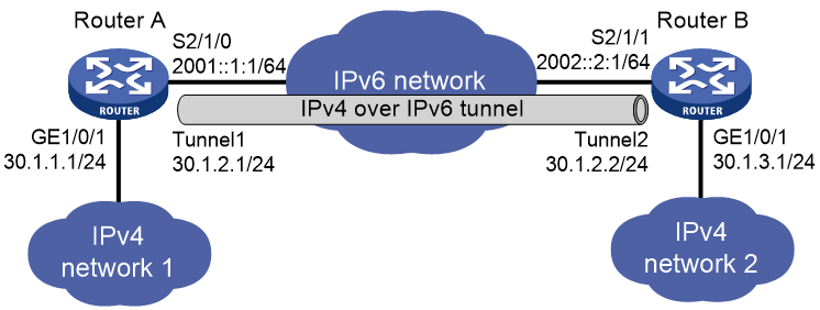
Example: Configuring an IPv4 over IPv6 tunnel
Network configuration
As shown in Figure 18, configure an IPv4 over IPv6 manual tunnel between Router A and Router B so the two networks can reach each other over the IPv6 network.
Procedure
Make sure Router A and Router B can reach each other through IPv6.
1. Configure Router A:
# Specify an IPv4 address for GigabitEthernet 1/0/1.
<RouterA> system-view
[RouterA] interface gigabitethernet 1/0/1
[RouterA-GigabitEthernet1/0/1] ip address 30.1.1.1 255.255.255.0
[RouterA-GigabitEthernet1/0/1] quit
# Specify an IPv6 address for Serial 2/1/0, which is the physical interface of the tunnel.
[RouterA] interface serial 2/1/0
[RouterA-Serial2/1/0] ipv6 address 2001::1:1 64
[RouterA-Serial2/1/0] quit
# Create IPv6 tunnel interface Tunnel 1.
[RouterA] interface tunnel 1 mode ipv6
# Specify an IPv4 address for the tunnel interface.
[RouterA-Tunnel1] ip address 30.1.2.1 255.255.255.0
# Specify the IP address of Serial 2/1/0 as the source address for the tunnel interface.
[RouterA-Tunnel1] source 2001::1:1
# Specify the IP address of Serial 2/1/1 on Router B as the destination address for the tunnel interface.
[RouterA-Tunnel1] destination 2002::2:1
[RouterA-Tunnel1] quit
# Configure a static route destined for IPv4 network 2 through the tunnel interface.
[RouterA] ip route-static 30.1.3.0 255.255.255.0 tunnel 1
2. Configure Router B:
# Specify an IPv4 address for GigabitEthernet 1/0/1.
<RouterB> system-view
[RouterB] interface gigabitethernet 1/0/1
[RouterB-GigabitEthernet1/0/1] ip address 30.1.3.1 255.255.255.0
[RouterB-GigabitEthernet1/0/1] quit
# Specify an IPv6 address for Serial 2/1/1, which is the physical interface of the tunnel.
[RouterB] interface serial 2/1/1
[RouterB-Serial2/1/1] ipv6 address 2002::2:1 64
[RouterB-Serial2/1/1] quit
# Create IPv6 tunnel interface Tunnel 2.
[RouterB] interface tunnel 2 mode ipv6
# Specify an IPv4 address for the tunnel interface.
[RouterB-Tunnel2] ip address 30.1.2.2 255.255.255.0
# Specify the IP address of Serial 2/1/1 as the source address for the tunnel interface.
[RouterB-Tunnel2] source 2002::2:1
# Specify the IP address of Serial 2/1/0 on Router A as the destination address for the tunnel interface.
[RouterB-Tunnel2] destination 2001::1:1
[RouterB-Tunnel2] quit
# Configure a static route destined for IPv4 network 1 through the tunnel interface.
[RouterB] ip route-static 30.1.1.0 255.255.255.0 tunnel 2
Verifying the configuration
# Use the display interface tunnel command to display the status of the tunnel interfaces on Router A and Router B. Verify that the tunnel interfaces are up. (Details not shown.)
# Verify that Router A and Router B can ping the IPv4 address of the peer interface GigabitEthernet 1/0/1. This example uses Router A.
[RouterA] ping -a 30.1.1.1 30.1.3.1
Ping 30.1.3.1 (30.1.3.1) from 30.1.1.1: 56 data bytes, press CTRL_C to break
56 bytes from 30.1.3.1: icmp_seq=0 ttl=255 time=3.000 ms
56 bytes from 30.1.3.1: icmp_seq=1 ttl=255 time=1.000 ms
56 bytes from 30.1.3.1: icmp_seq=2 ttl=255 time=0.000 ms
56 bytes from 30.1.3.1: icmp_seq=3 ttl=255 time=1.000 ms
56 bytes from 30.1.3.1: icmp_seq=4 ttl=255 time=1.000 ms
--- Ping statistics for 30.1.3.1 ---
5 packet(s) transmitted, 5 packet(s) received, 0.0% packet loss
round-trip min/avg/max/std-dev = 0.000/1.200/3.000/0.980 ms
Configuring a DS-Lite tunnel
Restrictions and guidelines for DS-Lite tunnel configuration
A B4 tunnel interface can establish a tunnel with only one AFTR tunnel interface, but an AFTR tunnel interface can establish tunnels with multiple B4 tunnel interfaces.
Follow these guidelines when you configure the B4 router of a DS-Lite tunnel:
· Do not specify the same source addresses for local tunnel interfaces in the same tunnel mode.
· The destination address specified for the tunnel interface on the B4 router must be the source address specified for the tunnel interface on the AFTR.
· To ensure correct packet forwarding, identify whether the destination IPv4 network and the IPv4 address of the local tunnel interface are on the same subnet. If they are not, configure a route reaching the destination IPv4 network through the tunnel interface. You can configure the route by using one of the following methods:
¡ Configure a static route, and specify the local tunnel interface as the egress interface or specify the IPv6 address of the peer tunnel interface as the next hop.
¡ Enable a dynamic routing protocol on both the local and remote tunnel interfaces.
For more information about route configuration, see Layer 3—IP Routing Configuration Guide.
· For a B4 router to automatically establish a DS-Lite tunnel with an AFTR, configure DHCPv6 client, static or dynamic IPv6 DNS, and the destination dhcp-alloc command on the B4 router. In addition, make sure a DHCPv6 server and an IPv6 DNS server (for dynamic DNS) exist in the network. For more information about DHCPv6 server, DHCPv6 client, and IPv6 DNS, see Layer 3—IP Services Configuration Guide.
Follow these guidelines when you configure the AFTR of a DS-Lite tunnel:
· Do not specify the same source addresses for local tunnel interfaces in the same tunnel mode.
· Enable NAT on the interface that is connected to the public IPv4 interface.
· The tunnel destination cannot be configured on the AFTR. The AFTR uses the address of the B4 router as the IPv6 address of the tunnel destination.
· It is not necessary to configure a route to the destination IPv4 address for forwarding packets through the tunnel interface.
Configuring the B4 router of a DS-Lite tunnel
1. Enter system view.
system-view
2. Enter IPv6 tunnel interface view.
interface tunnel number [ mode ipv6 ]
3. Specify an IPv4 address for the tunnel interface.
ip address ip-address { mask | mask-length } [ sub ]
4. Specify the source address or source interface for the tunnel.
source { ipv6-address | interface-type interface-number }
By default, no source address or interface is specified for the tunnel.
If you specify a source address, it is used as the source IPv6 address of tunneled packets.
If you specify a source interface, the lowest IPv6 address of this interface is used as the source IPv6 address of tunneled packets.
5. Specify the destination address for the tunnel.
destination { ipv6-address | dhcp-alloc interface-type interface-number }
By default, no destination address is configured for the tunnel.
The tunnel destination address must be the IPv6 address of the receiving interface on the tunnel peer. It is used as the destination IPv6 address of tunneled packets.
|
Parameter |
Remarks |
|
ipv6-address |
Specifies the tunnel source address configured on the AFTR as the destination address. |
|
dhcp-alloc interface-type interface-number |
Specifies an interface to obtain the AFTR's IPv6 address from the received DHCPv6 packets for automatic DS-Lite tunnel establishment. |
Configuring the AFTR of a DS-Lite tunnel
1. Enter system view.
system-view
2. Enter the view of the tunnel interface on the AFTR.
interface tunnel number [ mode ds-lite-aftr ]
3. Specify an IPv4 address for the tunnel interface.
ip address ip-address { mask | mask-length } [ sub ]
4. Specify the source address or source interface for the tunnel.
source { ipv6-address | interface-type interface-number }
By default, no source address or interface is specified for the tunnel.
The specified source address or the lowest IPv6 address of the specified source interface is used as the source IPv6 address of tunneled packets.
5. Return to system view.
quit
6. Enter the view of the interface that is connected to the IPv4 public network.
interface interface-type interface-number
7. Enable DS-Lite tunneling on the interface.
ds-lite enable
By default, DS-Lite tunneling is disabled.
Only after you use this command, the AFTR can tunnel IPv4 packets from the public IPv4 network to the B4 router.
8. Display information about the connected B4 routers on the AFTR.
display ds-lite b4 information
Example: Configuring a DS-Lite tunnel
Network configuration
As shown in Figure 19, to enable hosts in the private IPv4 network to access the public IPv4 network over the IPv6 network, perform the following tasks:
· Configure a DS-Lite tunnel between Router A and Router B.
· Configure NAT on GigabitEthernet 1/0/1 on the AFTR.
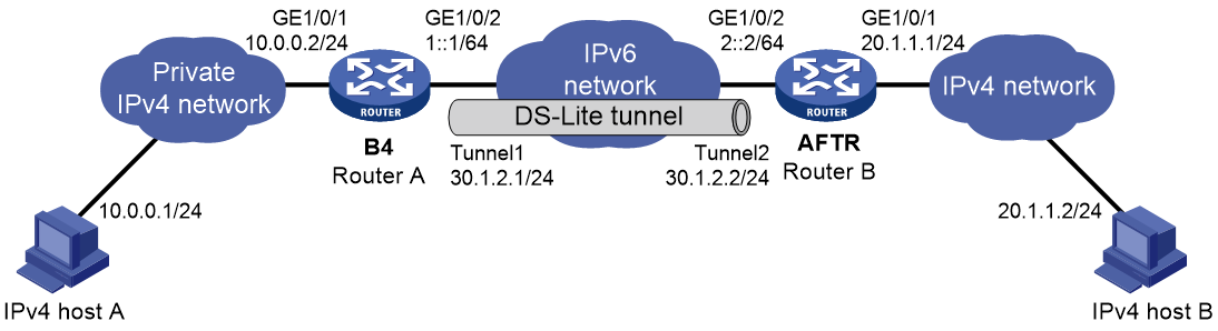
Procedure
Make sure Router A and Router B can reach each other through IPv6.
1. Configure Router A:
# Specify an IPv4 address for GigabitEthernet 1/0/1.
<RouterA> system-view
[RouterA] interface gigabitethernet 1/0/1
[RouterA-GigabitEthernet1/0/1] ip address 10.0.0.2 255.255.255.0
[RouterA-GigabitEthernet1/0/1] quit
# Specify an IPv6 address for GigabitEthernet 1/0/2, which is the physical interface of the tunnel.
[RouterA] interface gigabitethernet 1/0/2
[RouterA-GigabitEthernet1/0/2] ipv6 address 1::1 64
[RouterA-GigabitEthernet1/0/2] quit
# Create IPv6 tunnel interface Tunnel 1.
[RouterA] interface tunnel 1 mode ipv6
# Specify an IPv4 address for the tunnel interface.
[RouterA-Tunnel1] ip address 30.1.2.1 255.255.255.0
# Specify the IP address of GigabitEthernet 1/0/2 as the source address for the tunnel interface.
[RouterA-Tunnel1] source 1::1
# Specify IP address of GigabitEthernet 1/0/2 on Router B as the destination address for the tunnel interface.
[RouterA-Tunnel1] destination 2::2
[RouterA-Tunnel1] quit
# Configure a static route to the public IPv4 network through the tunnel interface.
[RouterA] ip route-static 20.1.1.0 255.255.255.0 tunnel 1
2. Configure Router B:
# Specify an IPv4 address for GigabitEthernet 1/0/1.
<RouterB> system-view
[RouterB] interface gigabitethernet 1/0/1
[RouterB-GigabitEthernet1/0/1] ip address 20.1.1.1 24
[RouterB-GigabitEthernet1/0/1] quit
# Specify an IPv6 address for GigabitEthernet 1/0/2, which is the physical interface of the tunnel.
[RouterB] interface gigabitethernet 1/0/2
[RouterB-GigabitEthernet1/0/2] ipv6 address 2::2 64
[RouterB-GigabitEthernet1/0/2] quit
# Create DS-Lite tunnel interface Tunnel 2.
[RouterB] interface tunnel 2 mode ds-lite-aftr
# Configure an IPv4 address for the tunnel interface.
[RouterB-Tunnel2] ip address 30.1.2.2 255.255.255.0
# Specify GigabitEthernet 1/0/2 as the source interface of the tunnel interface.
[RouterB-Tunnel2] source gigabitethernet 1/0/2
[RouterB-Tunnel2] quit
# Enable DS-Lite tunneling on GigabitEthernet 1/0/1.
[RouterB] interface gigabitethernet 1/0/1
[RouterB-GigabitEthernet1/0/1] ds-lite enable
# Enable NAT on GigabitEthernet 1/0/1 and use the IP address of GigabitEthernet 1/0/1 as the translated address.
[RouterB-GigabitEthernet1/0/1] nat outbound
[RouterB-GigabitEthernet1/0/1] quit
3. On host A, specify the IP address for the host as 10.0.0.1 and configure a static route to 20.1.1.0/24 with next hop 10.0.0.2. (Details not shown.)
4. On host B, specify the IP address for the host as 20.1.1.2. (Details not shown.)
Verifying the configuration
# Use the display interface tunnel command to display the status of the tunnel interfaces on Router A and Router B. Verify that the tunnel interfaces are up. (Details not shown.)
# Verify that host A can ping host B.
C:\> ping 20.1.1.2
Pinging 20.1.1.2 with 32 bytes of data:
Reply from 20.1.1.2: bytes=32 time=51ms TTL=255
Reply from 20.1.1.2: bytes=32 time=44ms TTL=255
Reply from 20.1.1.2: bytes=32 time=1ms TTL=255
Reply from 20.1.1.2: bytes=32 time=1ms TTL=255
Ping statistics for 20.1.1.2:
Packets: Sent = 4, Received = 4, Lost = 0 (0% loss),
Approximate round trip times in milli-seconds:
Minimum = 1ms, Maximum = 51ms, Average = 24ms
IPv6 over IPv6 tunneling
About IPv6 over IPv6 tunneling
IPv6 over IPv6 tunneling (RFC 2473) enables isolated IPv6 networks to communicate with each other over another IPv6 network. For example, two isolated IPv6 networks that do not want to show their addresses to the Internet can use an IPv6 over IPv6 tunnel to communicate with each other.
Figure 20 Principle of IPv6 over IPv6 tunneling
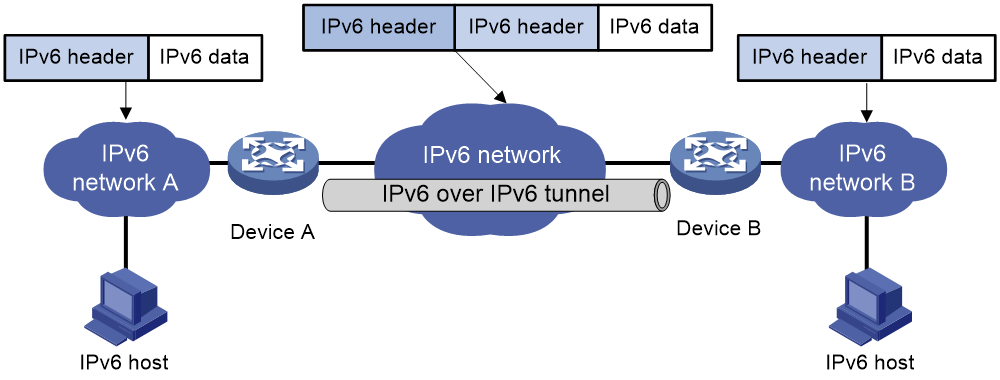
Figure 20 shows the encapsulation and de-encapsulation processes.
· Encapsulation:
a. After receiving an IPv6 packet, Device A submits it to the IPv6 protocol stack.
b. The IPv6 protocol stack uses the destination IPv6 address of the packet to find the egress interface. If the egress interface is the tunnel interface, the stack delivers it to the tunnel interface.
c. After receiving the packet, the tunnel interface adds an IPv6 header to it and submits it to the IPv6 protocol stack.
d. The IPv6 protocol stack forwards the packet according to its destination IPv6 address.
· De-encapsulation:
a. Upon receiving the IPv6 packet, Device B delivers it to the IPv6 protocol stack.
b. The IPv6 protocol stack checks the protocol type of the data portion encapsulated in the IPv6 packet. If the encapsulation protocol is IPv6, the stack delivers the packet to the tunnel module.
c. The tunnel module de-encapsulates the packet and sends it back to the IPv6 protocol stack.
d. The IPv6 protocol stack forwards the IPv6 packet.
Restrictions and guidelines: IPv6 over IPv6 tunnel configuration
Follow these guidelines when you configure an IPv6 over IPv6 tunnel:
· The tunnel destination address specified on the local device must be identical with the tunnel source address specified on the tunnel peer device.
· Do not specify the same source and destination addresses for local tunnel interfaces in the same tunnel mode.
· The IPv6 address of the tunnel interface cannot be on the same subnet as the destination address configured for the tunnel interface.
· To ensure correct packet forwarding, identify whether the destination IPv6 network and the IPv6 address of the local tunnel interface are on the same subnet. If they are not, configure a route reaching the destination IPv6 network through the tunnel interface. You can configure the route by using one of the following methods:
¡ Configure a static route, and specify the local tunnel interface as the egress interface or specify the IPv6 address of the peer tunnel interface as the next hop.
¡ Enable a dynamic routing protocol on both the local and remote tunnel interfaces.
For more information about route configuration, see Layer 3—IP Routing Configuration Guide.
· The destination address of the route passing the tunnel interface cannot be on the same subnet as the destination address configured for the tunnel interface.
IPv6 over IPv6 tunnel configuration tasks at a glance
To configure an IPv6 over IPv6 tunnel, perform the following tasks:
1. Configuring an IPv6 over IPv6 tunnel
2. (Optional.) Enabling dropping IPv6 packets that use IPv4-compatible IPv6 addresses
Configuring an IPv6 over IPv6 tunnel
1. Enter system view.
system-view
2. Enter IPv6 tunnel interface view.
interface tunnel number [ mode ipv6 ]
3. Configure an IPv6 address for the tunnel interface.
See "Configuring basic IPv6 settings."
4. Configure the source address or source interface for the tunnel interface.
source { ipv6-address | interface-type interface-number }
By default, no source address or interface is configured for the tunnel.
If you specify a source address, it is used as the source IPv6 address of tunneled packets.
If you specify a source interface, the lowest IPv6 address of this interface is used as the source IPv6 address of tunneled packets.
5. Configure the destination address for the tunnel interface.
destination ipv6-address
By default, no destination address is configured for the tunnel.
The tunnel destination address must be the IPv6 address of the receiving interface on the tunnel peer. It is used as the destination IPv6 address of tunneled packets.
6. (Optional.) Set the maximum number of nested encapsulations of a packet.
encapsulation-limit number
By default, there is no limit to the nested encapsulations of a packet.
Enabling dropping IPv6 packets that use IPv4-compatible IPv6 addresses
1. Enter system view.
system-view
2. Enable dropping IPv6 packets that use IPv4-compatible IPv6 addresses.
tunnel discard ipv4-compatible-packet
By default, IPv6 packets that use IPv4-compatible IPv6 addresses are not dropped.
IPv6 over IPv6 tunnel configuration examples
Example: Configuring an IPv6 over IPv6 tunnel
Network configuration
As shown in Figure 21, configure an IPv6 over IPv6 tunnel between Router A and Router B so the two networks can reach each other without disclosing their IPv6 addresses.
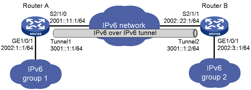
Procedure
Make sure Router A and Router B can reach each other through IPv6.
1. Configure Router A:
# Specify an IPv6 address for GigabitEthernet 1/0/1.
<RouterA> system-view
[RouterA] interface gigabitethernet 1/0/1
[RouterA-GigabitEthernet1/0/1] ipv6 address 2002:1::1 64
[RouterA-GigabitEthernet1/0/1] quit
# Specify an IPv6 address for Serial 2/1/0, which is the physical interface of the tunnel.
[RouterA] interface serial 2/1/0
[RouterA-Serial2/1/0] ipv6 address 2001::11:1 64
[RouterA-Serial2/1/0] quit
# Create IPv6 tunnel interface Tunnel 1.
[RouterA] interface tunnel 1 mode ipv6
# Specify an IPv6 address for the tunnel interface.
[RouterA-Tunnel1] ipv6 address 3001::1:1 64
# Specify the IP address of Serial 2/1/0 as the source address for the tunnel interface.
[RouterA-Tunnel1] source 2001::11:1
# Specify the IP address of Serial 2/1/1 on Router B as the destination address for the tunnel interface.
[RouterA-Tunnel1] destination 2002::22:1
[RouterA-Tunnel1] quit
# Configure a static route destined for the IPv6 network group 2 through the tunnel interface.
[RouterA] ipv6 route-static 2002:3:: 64 tunnel 1
2. Configure Router B:
# Specify an IPv6 address for GigabitEthernet 1/0/1.
<RouterB> system-view
[RouterB] interface gigabitethernet 1/0/1
[RouterB-GigabitEthernet1/0/1] ipv6 address 2002:3::1 64
[RouterB-GigabitEthernet1/0/1] quit
# Specify an IPv6 address for Serial 2/1/1, which is the physical interface of the tunnel.
[RouterB] interface serial 2/1/1
[RouterB-Serial2/1/1] ipv6 address 2002::22:1 64
[RouterB-Serial2/1/1] quit
# Create IPv6 tunnel interface Tunnel 2.
[RouterB] interface tunnel 2 mode ipv6
# Specify an IPv6 address for the tunnel interface.
[RouterB-Tunnel2] ipv6 address 3001::1:2 64
# Specify the IP address of Serial 2/1/1 as the source address for the tunnel interface.
[RouterB-Tunnel2] source 2002::22:1
# Specify the IP address of Serial 2/1/0 on Router A as the destination address for the tunnel interface.
[RouterB-Tunnel2] destination 2001::11:1
[RouterB-Tunnel2] quit
# Configure a static route destined for the IPv6 network group 1 through the tunnel interface.
[RouterB] ipv6 route-static 2002:1:: 64 tunnel 2
Verifying the configuration
# Use the display ipv6 interface command to display the status of the tunnel interfaces on Router A and Router B. Verify that the tunnel interfaces are up. (Details not shown.)
# Verify that Router A and Router B can ping the IPv6 address of the peer interface GigabitEthernet 1/0/1. This example uses Router A.
[RouterA] ping ipv6 -a 2002:1::1 2002:3::1
Ping6(56 data bytes) 2002:1::1 --> 2002:3::1, press CTRL_C to break
56 bytes from 2002:3::1, icmp_seq=0 hlim=64 time=9.000 ms
56 bytes from 2002:3::1, icmp_seq=1 hlim=64 time=1.000 ms
56 bytes from 2002:3::1, icmp_seq=2 hlim=64 time=0.000 ms
56 bytes from 2002:3::1, icmp_seq=3 hlim=64 time=0.000 ms
56 bytes from 2002:3::1, icmp_seq=4 hlim=64 time=0.000 ms
--- Ping6 statistics for 2002:3::1 ---
5 packet(s) transmitted, 5 packet(s) received, 0.0% packet loss
round-trip min/avg/max/std-dev = 0.000/2.000/9.000/3.521 ms