- Table of Contents
- Related Documents
-
| Title | Size | Download |
|---|---|---|
| 08-DDR configuration | 685.95 KB |
Contents
Restrictions: Hardware compatibility with DDR
Packet-triggered DDR tasks at a glance
Auto-dial DDR tasks at a glance
Route-triggered DDR tasks at a glance
Configuring basic settings for DDR
Configuring physical interfaces
Configuring link layer/network/routing protocols on the dialup interface
Associating a dial rule with a dialup interface
Restrictions and guidelines for traditional DDR
Configuring an interface to place calls
Configuring an interface to receive calls
Configuring a dialer interface to place calls
Configuring a dialer interface to receive calls
Configuring a dialup interface
Configuring attributes for a dialup interface
Configuring the buffer queue length for a dialup interface
Configuring keepalive parameters
Specifying traffic processing slots for a dialup interface
Restoring the default settings for a dialup interface
Restrictions and guidelines for PPP callback
Configuring the callback client
Configuring the callback server
Configuring ISDN caller number callback
About ISDN caller number callback
Restrictions and guidelines for ISDN caller number callback
Configuring a callback server by using traditional DDR
Configuring a callback server by using bundle DDR
Configuring dynamic route backup through DDR
About dynamic route backup through DDR
Restrictions and guidelines for dynamic route backup through DDR
Creating a dynamic route backup group
Assigning a dialup interface to a dynamic route backup group
Setting the secondary link disconnection delay
Setting the warm-up timer for dynamic route backup
Display and maintenance commands for DDR
Example: Configuring PSTN-based traditional DDR
Example: Configuring PSTN-based bundle DDR
Example: Configuring ISDN-based traditional DDR
Example: Configuring ISDN-based bundle DDR
Example: Configuring MP for DDR
Example: Configuring ISDN caller number callback
Example: Configuring Router-to-router PPP callback
Example: Configuring Router-to-PC PPP callback
Example: Configuring Windows server-to-router PPP callback
Example: Configuring circular dial string backup and Internet access
Example: Configuring dynamic route backup for traditional DDR
Example: Configuring dynamic route backup for bundle DDR
Example: Configuring dynamic route backup for multiple networks
Failure to establish a dialup connection
Configuring DDR
About DDR
Routers use dial-on-demand routing (DDR) for the following purposes:
· Setting up a dialup connection over PSTN/ISDN when communication needs arise.
· Tearing down the connection when the communication is complete.
In addition to PSTN/ISDN, Ethernet and ATM can use DDR to implement access control. For more information, see "Configuring PPPoE" and "Configuring ATM."
Interfaces in DDR
DDR uses the following dialup interfaces:
· Physical interfaces—Include the following interfaces:
¡ Asynchronous serial interfaces.
¡ Synchronous/asynchronous serial interfaces operating in asynchronous mode.
¡ AM interfaces.
¡ AUX interfaces.
¡ ISDN BRI interfaces.
¡ ISDN PRI interfaces.
¡ Cellular interfaces.
· Dialer interfaces—Logical interfaces used for DDR parameter configurations.
DDR implementations
DDR supports traditional DDR and bundle DDR.
Traditional DDR
You can configure traditional DDR by using the following methods:
· Configure DDR parameters directly on a physical interface.
The router places or receives calls through the physical interface.
The physical interface can have one or more call destinations.
This method applies when only one interface places or receives calls.
· Configure DDR parameters on a dialer interface.
A dialer interface is associated with a group of physical interfaces and selects a physical interface to place or receive calls.
A dialer interface can have one or more call destinations. A dialer interface with multiple call destinations can use any associated physical interface to place calls to any of the call destinations.
A physical interface can belong to only one dialer interface.
This method applies when one or more interfaces place or receive calls.
Bundle DDR
When using bundle DDR, you can configure DDR parameters only on a dialer interface.
A dialer interface corresponds to a dialer bundle. A dialer bundle can contain multiple physical interfaces. You can assign a priority to each physical interface in the dialer bundle. Each time a call is placed, the highest-priority physical interface available is selected. If multiple physical interfaces with the highest priority are available, these interfaces are selected in a round-robin manner.
A dialer interface can have only one call destination.
A physical interface can belong to multiple dialer bundles and can be used by multiple dialer interfaces at different times.
Comparison of traditional DDR and bundle DDR
Traditional DDR is based on one-to-one bindings between dial services and physical interfaces. A new dial service requires a new physical interface. As a result, traditional DDR has poor extensibility.
|
|
NOTE: A dial rule (configured by using the dialer-group rule command) defines one dial service. |
Figure 1 Relationships among physical interfaces, dialer interfaces, and call destinations in traditional DDR
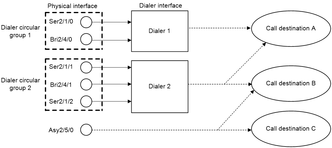
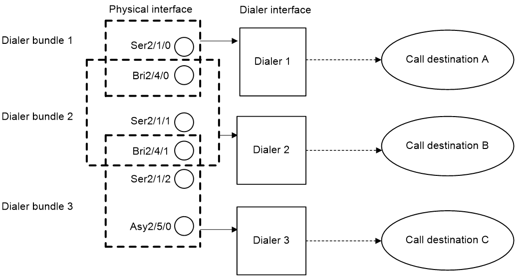
Bundle DDR is simpler and more flexible than traditional DDR. Bundle DDR separates physical interface configuration and logical configuration for calls and allows one-to-many bindings between dial services and physical interfaces. A physical interface can serve multiple dial services.
Figure 2 Relationships among physical interfaces, dialer interfaces, and call destinations in bundle DDR
DDR types
Depending on how DDR calls are triggered, DDR includes packet-triggered DDR, auto-dial DDR, and route-triggered DDR.
Packet-triggered DDR
You can define packets on a dialup interface as interesting and uninteresting by configuring access control rules. Only interesting packets trigger outgoing calls and reset the link idle-timeout timer.
Before a dialup connection is established, uninteresting packets will be dropped. After a dialup connection is established, uninteresting packets can be forwarded. When the link idle-timeout timer expires, DDR disconnects the connection.
For more information about interesting and uninteresting packets, see "Associating a dial rule with a dialup interface."
Auto-dial DDR
DDR automatically initiates a dialup connection to the remote end upon router startup without requiring a triggering packet. If the connection cannot be established, it will retry at the auto-dial interval. The established connection will not disconnect due to the idle-timeout timer expiration.
Route-triggered DDR
You can configure networks to be monitored and then associate a dialup interface with the networks. When no routes to the monitored networks exist, DDR creates a secondary link from the dialup interface to forward traffic. After the secondary link is activated, the system regularly checks the status of the primary link. When the primary link recovers, the secondary link is disconnected immediately or after the secondary link disconnection delay, depending on your configuration.
Restrictions: Hardware compatibility with DDR
|
Hardware |
DDR compatibility |
|
MSR810, MSR810-W, MSR810-W-DB, MSR810-LM, MSR810-W-LM, MSR810-10-PoE, MSR810-LM-HK, MSR810-W-LM-HK, MSR810-CNDE-SJK |
Yes |
|
MSR810-LMS, MSR810-LUS |
Yes |
|
MSR2600-6-X1, MSR2600-10-X1 |
Yes |
|
MSR 2630 |
Yes |
|
MSR3600-28, MSR3600-51 |
Yes |
|
MSR3600-28-SI, MSR3600-51-SI |
Yes |
|
MSR3600-28-X1, MSR3600-28-X1-DP, MSR3600-51-X1, MSR3600-51-X1-DP |
No |
|
MSR3610-I-DP, MSR3610-IE-DP, MSR3610-IE-ES, MSR3610-IE-EAD |
Yes |
|
MSR3610-X1, MSR3610-X1-DP, MSR3610-X1-DC, MSR3610-X1-DP-DC |
Yes |
|
MSR 3610, MSR 3620, MSR 3620-DP, MSR 3640, MSR 3660 |
Yes |
|
MSR3610-G, MSR3620-G |
Yes |
DDR tasks at a glance
Packet-triggered DDR tasks at a glance
To configure packet-triggered DDR, perform the following tasks:
1. Configuring basic settings for DDR
2. Associating a dial rule with a dialup interface
3. Configuring DDR dialup
4. Configuring attributes for a dialup interface
5. (Optional.) Configuring MP for DDR
6. (Optional.) Configuring PPP callback
7. (Optional.) Configuring ISDN caller number callback
8. (Optional.) Disconnecting a dialup link
Auto-dial DDR tasks at a glance
To configure auto-dial DDR, perform the following tasks:
1. Configuring basic settings for DDR
2. Configuring DDR dialup
3. Configuring attributes for a dialup interface
4. (Optional.) Configuring MP for DDR
6. (Optional.) Disconnecting a dialup link
Route-triggered DDR tasks at a glance
To configure route-triggered DDR, perform the following tasks:
1. Configuring basic settings for DDR
2. Configuring DDR dialup
3. Configuring attributes for a dialup interface
4. (Optional.) Configuring MP for DDR
5. Configuring dynamic route backup through DDR
6. (Optional.) Disconnecting a dialup link
Configuring basic settings for DDR
Configuring physical interfaces
The router uses ISDN BRI and ISDN PRI interfaces to connect to an ISDN network. It uses asynchronous serial interfaces, synchronous/asynchronous serial interfaces, AM interfaces, and AUX interfaces to connect to a PSTN network. For information about configuring these physical interfaces, see Interface Configuration Guide.
When you configure a synchronous/asynchronous serial interface, follow these guidelines:
· If the connected modem is asynchronous, perform the following tasks:
¡ Configure the interface as an asynchronous interface by using the physical-mode async command and to operate in protocol mode by using the async-mode protocol command.
¡ Configure the call-in/call-out rights for the modem on the corresponding user line for the interface.
· If the connected modem is synchronous, configure the interface as a synchronous serial interface by using the physical-mode sync command.
For more information about modem management, see "Managing a modem."
Configuring link layer/network/routing protocols on the dialup interface
Dialup interfaces support PPP, IP, RIP, and OSPF. For information about configuring these protocols, see "Configuring PPP," Layer 3—IP Services Configuration Guide, and Layer 3—IP Routing Configuration Guide.
When you configure PPP, follow these guidelines:
· For traditional DDR, configure PPP commands on the same interface as DDR parameters.
· For bundle DDR:
¡ On the calling side, perform the following tasks:
- Configure PPP commands on dialer interfaces.
- Configure the same PPP commands on physical interfaces to ensure successful PPP link parameters negotiation.
¡ On the called side, configure PPP commands on physical interfaces.
Associating a dial rule with a dialup interface
About this task
A dial rule determines when a dialup interface initiates DDR calls. You need to configure dial rules only on the initiator of DDR calls.
You can configure a dial rule to match only IP packets or use an ACL to match packets.
Permitted protocol packets or packets that match a permit statement of an ACL are interesting packets. When receiving an interesting packet, DDR performs one of the following operations:
· Sends it out and resets the idle-timeout timer if a link is present.
· Initiates a new call to establish a link if no link is present.
Denied protocol packets or packets that match a deny statement of an ACL are uninteresting packets. When receiving an uninteresting packet, DDR performs one of the following operations:
· Sends it out without resetting the idle-timeout timer if a link is present.
· Drops it if no link is present.
Restrictions and guidelines
For DDR to forward packets correctly, configure a dial rule and associate it with the dialup interface.
A dialup interface can be associated with only one dialer group.
Procedure
1. Enter system view.
system-view
2. Create a dialer group and configure a dial rule.
dialer-group group-number rule { ip | ipv6 } { deny | permit | acl { acl-number | name acl-name } }
3. Enter dialup interface view.
interface interface-type interface-number
4. Associate the dialer group with the dialup interface.
dialer-group group-number
By default, a dialup interface is not associated with a dialer group.
Configuring traditional DDR
Restrictions and guidelines for traditional DDR
For traditional DDR, you can configure PAP or CHAP authentication (see "Configuring PPP"). As a best practice, configure PAP or CHAP authentication for security purposes.
When you configure PAP or CHAP authentication, follow these guidelines:
· Configure PAP or CHAP authentication on a physical interface if you configure DDR parameters directly on the physical interface.
· Configure PAP or CHAP authentication on the dialer interface if you configure DDR parameters through a dialer circular group.
Configuring an interface to place calls
Restrictions and guidelines for configuring an interface to place calls
To configure an interface to place calls, enable DDR and configure dial strings.
When you configure an interface to place calls, follow these guidelines:
· To configure an interface to place calls, you can make the configuration on the physical interface or through a dialer circular group. To configure multiple interfaces to place calls, you can make the configuration only through a dialer circular group.
· To configure an interface to place calls to a single site, use the dialer number or dialer route command to specify the dial string to reach the site. To configure an interface to place calls to multiple sites, use the dialer route command multiple times to specify the dial strings to reach the sites.
· You can use the dialer route command to configure multiple dial strings for a single destination for dial backup. If a dial string fails to reach the destination, another dial string will be used.
Configuring an interface to place calls directly on a physical interface
1. Enter system view.
system-view
2. Enter physical interface view.
interface interface-type interface-number
3. Enable traditional DDR.
dialer circular enable
By default, traditional DDR is disabled.
4. Configure a dial string.
¡ Configure a dial string for the interface to place calls to a single site.
dialer number dial-number
¡ Configure a dial string for the interface to place calls to multiple sites.
dialer route ip next-hop-address [ mask network-mask-length ] [ vpn-instance vpn-instance-name ] dial-number number [ broadcast ]
By default, no dial string is configured.
Configuring an interface to place calls through a dialer circular group
1. Enter system view.
system-view
2. Create a dialer interface and enter its view.
interface dialer number
3. Enable traditional DDR on the interface.
dialer circular enable
By default, traditional DDR is disabled on an interface.
4. Configure a dial string.
¡ Configure a dial string for the interface to place calls to a single site.
dialer number dial-number
¡ Configure a dial string for the interface to place calls to multiple sites.
dialer route ip next-hop-address [ mask network-mask-length ] [ vpn-instance vpn-instance-name ] dial-number number [ interface interface-type interface-number ] [ broadcast ]
By default, no dial string is configured.
5. Return to system view.
quit
6. Enter physical interface view.
interface interface-type interface-number
7. Assign the physical interface to a dialer circular group.
dialer circular group number
By default, a physical interface does not belong to a dialer circular group.
Make sure the number arguments in the interface dialer and dialer circular group commands use the same value.
8. Configure the priority of the physical interface in the dialer circular group.
dialer priority priority
The default setting is 1.
When configuring one interface to place calls, you do not need to configure this command.
When configuring multiple interfaces to place calls, you must configure this command. Each time a call is placed, the highest-priority physical interface available is selected. If one of the available physical interfaces with the highest priority is selected, the interfaces are selected in a round-robin manner.
Configuring an interface to receive calls
Restrictions and guidelines for configuring an interface to receive calls
To configure an interface to receive calls, you only need to enable DDR on the interface.
When you configure an interface to receive calls, follow these guidelines:
· To configure one interface to receive calls, you can make the configuration on the physical interface or through a dialer circular group.
· To configure multiple interfaces to receive calls, you can make the configuration only through a dialer circular group.
· To receive calls from multiple remote sites, configure the dialer route command multiple times. For the receiving interface to authenticate the caller, specify the user hostname option when configuring this command. The receiving interface accepts the call only when the IP address and host name of the caller match the configured ones.
Configuring an interface to receive calls directly on a physical interface
1. Enter system view.
system-view
2. Enter physical interface view.
interface interface-type interface-number
3. Enable traditional DDR on the interface.
dialer circular enable
By default, traditional DDR is disabled on an interface.
After this command is configured on an interface, the interface can receive calls from any callers if the caller authentication feature is not configured.
4. (Optional.) Configure the interface to authenticate the caller.
dialer route ip next-hop-address [ mask network-mask-length ] [ vpn-instance vpn-instance-name ] [ broadcast | user hostname ] *
By default, the caller authentication feature is not configured.
Configuring an interface to receive calls through a dialer circular group
1. Enter system view.
system-view
2. Create a dialer interface and enter its view.
interface dialer number
3. Enable traditional DDR on the interface.
dialer circular enable
By default, traditional DDR is disabled on an interface.
After this command is configured on an interface, the interface can receive calls from any callers if the caller authentication feature is not configured.
4. (Optional.) Configure the interface to authenticate the caller.
dialer route ip next-hop-address [ mask network-mask-length ] [ vpn-instance vpn-instance-name ] [ broadcast | user hostname ] *
5. Return to system view.
quit
6. Enter physical interface view.
interface interface-type interface-number
7. Assign the physical interface to a dialer circular group.
dialer circular group number
By default, a physical interface does not belong to a dialer circular group.
Make sure the number arguments in the interface dialer and dialer circular group commands use the same value.
Configuring bundle DDR
Configuring a dialer interface to place calls
Restrictions and guidelines
To configure a dialer interface to place calls, enable DDR and configure a dial string to reach the remote site. Only one dial string can be configured for each dialer interface.
At the initiator end, the system selects a dialer interface according to the dialer-group rule command configuration. The physical interface uses the configuration of the selected dialer interface to place calls.
The initiator end can optionally authenticate the receiving end. To authenticate the receiving end, configure PAP or CHAP authentication on the dialer interface.
Procedure
system-view
2. Create a dialer interface and enter its view.
interface dialer number
3. Enable bundle DDR on the interface.
dialer bundle enable
By default, bundle DDR is disabled.
4. Specify a dial string.
dialer number dial-number
5. Configure the initiator to authenticate the receiving end.
To authenticate the receiving end, configure PAP or CHAP authentication on the dialer interface. For more information, see "Configuring PPP."
6. Return to system view.
quit
7. Enter physical interface view.
interface interface-type interface-number
8. Assign the physical interface to a dialer bundle.
dialer bundle-member number [ priority priority ]
By default, a physical interface does not belong to a dialer bundle.
Make sure the number arguments in the interface dialer and dialer bundle-member commands use the same value.
Configuring a dialer interface to receive calls
Restrictions and guidelines
To configure a dialer interface to receive calls, you only need to enable DDR on the interface. At the receiving end, configure PAP or CHAP authentication (see "Configuring PPP") on the physical interface and the dialer peer-name command on the dialer interface. The device compares the remote username obtained in PPP authentication with the host names configured by using the dialer peer-name command. Then, the device determines which dialer interface receives which call.
Procedure
1. Enter system view.
system-view
2. Create a dialer interface and enter its view.
interface dialer number
3. Enable bundle DDR on the interface.
dialer bundle enable
By default, bundle DDR is disabled.
4. Configure the host name of the remote device.
dialer peer-name username
You can configure a maximum number of 255 remote usernames for a dialer interface. This enables one dialer interface to receive calls from multiple physical interfaces.
5. Return to system view.
quit
6. Enter physical interface view.
interface interface-type interface-number
7. Assign the physical interface to a dialer bundle.
dialer bundle-member number [ priority priority ]
By default, a physical interface does not belong to a dialer bundle.
Make sure the number arguments in the interface dialer and dialer bundle-member commands use the same value.
Configuring a dialup interface
Configuring attributes for a dialup interface
1. Enter system view.
system-view
2. Enter dialup interface view.
interface interface-type interface-number
3. Set a description.
description text
The default setting is in the format of interface-name Interface, for example, Dialer1 Interface.
4. Set the MTU.
mtu size
The default setting is 1500 bytes.
5. Set the expected bandwidth.
bandwidth bandwidth-value
By default, the expected bandwidth (in kbps) is the interface baud rate divided by 1000.
The expected bandwidth of an interface affects the link costs in OSPF, OSPFv3, and IS-IS. For more information, see Layer 3—IP Routing Configuration Guide.
6. Bring up the dialup interface.
undo shutdown
By default, a dialup interface is up.
Setting call timers
About this task
The call timers includes the following types:
· Link idle-timeout timer—Starts upon establishment of a link. When the timer expires, DDR disconnects the link.
· Holddown timer—Starts upon disconnection of a link. The call attempt to bring up this link can be made only after the timer expires. This timer prevents a remote stored program controlled switch (SPCS) from being overloaded.
· Compete-idle timer—Starts if all physical interfaces are unavailable when DDR initiates a new call. When the amount of idle time of a link reaches the compete-idle timer setting, the link disconnects.
· Wait-carrier timer—Limits the amount of time DDR waits for a connection to be established for a call. A wait-carrier timer starts when a call is placed. If the connection is not established before the timer expires, DDR terminates the call.
Procedure
1. Enter system view.
system-view
2. Enter dialup interface view.
interface interface-type interface-number
3. Set the link idle-timeout timer.
dialer timer idle idle [ in | in-out ]
By default, the timer is 120 seconds, and only outgoing interesting packets reset this timer.
4. Set the holddown timer.
dialer timer enable interval
The default setting is 5 seconds.
5. Set the compete-idle timer.
dialer timer compete compete-idle
The default setting is 20 seconds.
6. Set the wait-carrier timer.
dialer timer wait-carrier wait-carrier
The default setting is 60 seconds.
Configuring the buffer queue length for a dialup interface
About this task
With a buffer queue, the dialup interface buffers the packet until a connection is available for packet sending. If no connection is available when a dialup interface without a buffer queue receives a packet, the dialup interface drops the packet.
Procedure
1. Enter system view.
system-view
2. Enter dialup interface view.
interface interface-type interface-number
3. Set the buffer queue length.
dialer queue-length packets
By default, packets are not buffered.
Configuring keepalive parameters
1. Enter system view.
system-view
2. Enter dialup interface view.
interface interface-type interface-number
3. Set the keepalive interval.
timer-hold seconds
The default setting is 10 seconds.
4. Set the keepalive retry limit.
timer-hold retry retries
The default setting is five. A link is removed after the keepalive retry limit is reached.
5. Set the polling interval.
timer-hold period
The default setting is 10 seconds.
Specifying traffic processing slots for a dialup interface
About this task
Specify traffic processing slots if a feature requires that all traffic on a dialup interface be processed on the same slot.
For high availability, you can specify one primary and one backup traffic processing slot by using the service command and the service standby command, respectively.
If you specify both primary and backup slots for an interface, traffic on that interface is processed as follows:
· The backup slot takes over when the primary slot becomes unavailable. The backup slot continues to process traffic for the interface after the primary slot becomes available again. The switchover will not occur until the backup slot becomes unavailable.
· When no specified traffic processing slots are available, the traffic is processed on the slot at which it arrives. Then, the processing slot that first becomes available again takes over.
If you do not specify a primary or a backup traffic processing slot for an interface, traffic on that interface is processed on the slot at which the traffic arrives.
Restrictions and guidelines
To avoid processing slot switchover, specify the primary slot before specifying the backup slot. If you specify the backup slot before specifying the primary slot, traffic is switched over to the primary slot immediately after you specify the primary slot.
Procedure
1. Enter system view.
system-view
2. Enter dialup interface view.
interface interface-type interface-number
3. Specify a primary traffic processing slot for the interface.
In IRF mode:
service slot slot-number
By default, no primary traffic processing slot is specified for an interface.
Support for this command depends on the device model.
4. Specify a backup traffic processing slot for the interface.
In IRF mode:
service standby slot slot-number
By default, no backup traffic processing slot is specified for an interface.
Support for this command depends on the device model.
Restoring the default settings for a dialup interface
Restrictions and guidelines
The default command might interrupt ongoing network services. Make sure you are fully aware of the impact of this command when you execute it on a live network.
The default command might fail to restore the default settings for some commands for reasons such as command dependencies or system restrictions. Use the display this command in interface view to identify these commands. Use the undo forms of these commands or follow the command reference to individually restore their default settings. If your restoration attempt still fails, follow the error message instructions to resolve the problem.
Procedure
1. Enter system view.
system-view
2. Enter dialup interface view.
interface interface-type interface-number
3. Restore the default settings for the interface.
default
Configuring MP for DDR
About this task
After MP is configured on DDR links, the device provides traffic statistics at the specified interval and brings up or shuts down links based on the following settings:
· Traffic threshold—Specifies a threshold as a percentage of aggregate link bandwidth for DDR to bring up or shut down a link in an MP bundle.
· Upper limit to links—Specifies the maximum number of links that DDR can bring up in an MP bundle.
· Lower limit to links—Specifies the minimum number of links that DDR must bring up to meet the minimum bandwidth requirements. When triggered, DDR brings up the minimum number of links first. These links are not disconnected based on the link idle-timeout timer.
DDR brings up links in an MP bundle until either of the following conditions is met:
· The links reach the upper limit.
· The percentage of traffic to the bandwidth of all activated links is equal to or lower than the traffic threshold.
DDR shuts down links in an MP bundle until either of the following conditions is met:
· The links reach the lower limit.
· The percentage of traffic to the bandwidth of (n-1) activated links is equal to or higher than the traffic threshold.
For more information about MP, see "Configuring MP."
Restrictions and guidelines
If you set the traffic threshold to 0, DDR brings up all available links when triggered by auto-dial or packets. In addition, DDR does not disconnect these links based on the link idle-timeout timer.
If you do not set a traffic threshold, the upper limit does not take effect.
· If you set a lower limit, the system uses the minimum number of links for MP bundling.
· If you do not set a lower limit, the system uses one link for MP bundling.
As a best practice, set the traffic threshold, upper limit, and lower limit on only one end of a call. If the configured values are different on the two ends of a call, the following values take effect:
· The smaller traffic threshold.
· The smaller upper limit.
· The greater lower limit.
Procedure
1. Enter system view.
system-view
2. Set the interval for DDR to provide traffic statistics.
dialer flow-interval interval
The default is 20 seconds.
This command provides traffic statistics on dialup links for MP.
3. Enter dialer interface view.
interface dialer number
4. Enable MP for the interface.
ppp mp
For more information about MP, see "Configuring MP."
Configure this command on the corresponding physical interfaces.
5. (Optional.) Set the traffic threshold.
dialer threshold traffic-percentage [ in | in-out | out ]
By default, no traffic threshold is set.
6. (Optional.) Set the upper limit of links in an MP bundle.
ppp mp max-bind max-bind-num
The default setting is 16.
For more information about this command, see "Configuring MP."
7. (Optional.) Set the lower limit of links in an MP bundle.
ppp mp min-bind min-bind-num
By default, the lower limit is 0, and DDR brings up links depending on traffic size.
For more information about this command, see "Configuring MP."
Configuring PPP callback
About PPP callback
PPP callback uses the client/server model where the calling party is the callback client and the called party is the callback server. The client first initiates a call, and the server decides whether to place a return call. If a return call is needed, the callback server disconnects the call and places a return call according to the username or callback number.
PPP callback has the following benefits:
· Enhanced security—The server places a return call to the locally configured number, which prevents caller number spoofing.
· Reduced charges—The charge payer can be changed when the charge rates are different in the two directions.
Restrictions and guidelines for PPP callback
When you configure PPP callback on an interface, follow these restrictions and guidelines:
· PPP callback requires authentication. Configure PAP or CHAP authentication on both physical and dialer interfaces on the callback client and server.
· To provide enough time for callback, make sure the holddown timer on the client is 10 or more seconds longer than that on the server. As a best practice, set the holddown timer to 5 seconds (the default) on the server and to 15 seconds on the client.
· Do not configure dynamic route backup on the interface. Otherwise, the interface does not accept incoming calls or outgoing calls other than calls initiated for the dynamic route backup feature.
Configuring the callback client
About this task
The callback client can place calls to the remote end and receive return calls from the callback server. The callback server can be a router or Windows server that supports the callback server feature.
You can configure the callback client to use traditional DDR or bundle DDR.
Configuring the callback client by using traditional DDR
1. Enter system view.
system-view
2. Enter dialup interface view.
interface interface-type interface-number
3. Enable the interface to send callback requests.
ppp callback client
By default, an interface does not send callback requests.
4. Configure the dial string for a Windows server to call back.
ppp callback ntstring dial-number
By default, no dial string is configured for a Windows server to call back.
Configure this command if the Windows server requires callback clients to send callback numbers.
Configuring the callback client by using bundle DDR
1. Enter system view.
system-view
2. Enter dialer interface view.
interface dialer number
3. Enable the interface to send callback requests.
ppp callback client
By default, an interface does not send callback requests.
4. Configure the dial string for a Windows server to place return calls.
ppp callback ntstring dial-number
By default, no dial string is configured for a Windows server to call back.
Configure this command if a Windows server requires callback clients to send callback numbers.
Configuring the callback server
About this task
You can configure the callback server to use traditional DDR or bundle DDR. The configuration differences are as follows:
· Traditional DDR—The callback server can place return calls according to either of the following:
¡ Dial string configured with the dialer route command (PPP authentication must be configured).
¡ Username for PPP authentication.
You must select either method by using the dialer callback-center command.
· Bundle DDR—The callback server can place return calls only according to callback numbers.
Configuring the callback server by using traditional DDR
1. Enter system view.
system-view
2. Enter dialup interface view.
interface interface-type interface-number
3. Enable the interface to accept callback requests.
ppp callback server
By default, an interface does not accept callback requests.
4. Specify whether the dial string for callback is determined according to the authenticated username or according to a configured username.
dialer callback-center [ dial-number | user ] *
By default, callback is not performed.
5. Return to system view.
quit
6. Configure a dial string for callback.
¡ (Method 1) Execute the following commands in sequence to configure a callback user and a dial string:
local-user user-name class network
service-type ppp
authorization-attribute callback-number callback-number
¡ (Method 2) Execute the following commands in sequence to configure a dial string:
interface interface-type interface-number
dialer route ip next-hop-address [ mask network-mask-length ] [ vpn-instance vpn-instance-name ] dial-number dial-number [ interface interface-type interface-number ] [ broadcast | user hostname ] *
If a callback client uses the dynamically assigned IP address, use method 1 rather than method 2.
If the dial string for callback is determined according to the authenticated username, use method 1.
If the dial string for callback is determined according to the configured username, use method 2.
Configuring the callback server by using bundle DDR
1. Enter system view.
system-view
2. Enter dialer interface view.
interface dialer number
3. Enable the interface to accept callback requests.
ppp callback server
By default, an interface does not accept callback requests.
4. Configure the interface to determine the dial string for callback according to the authenticated username.
dialer callback-center dial-number
By default, callback is not performed.
5. Return to system view.
quit
6. Configure the callback user and callback number.
¡ Create a local user and enter local user view.
local-user user-name class network
¡ Specify the service type for users.
service-type ppp
By default, a local user is not authorized to use any service.
¡ Configure authorization attributes for a local user or user group.
authorization-attribute callback-number callback-number
By default, no authorization attributes are configured for a local user or user group.
Configuring ISDN caller number callback
About ISDN caller number callback
This feature allows the device to perform the following operations:
· Screen incoming calls based on the ISDN caller number.
· Determine whether to accept a call or initiate a callback according to the screening results.
Callback
A callback is a return call from the call receiver (server) to the call initiator (client). The client initiates a call, and the server determines whether to initiate a callback to the client. If yes, the server disconnects the call and places a return call to the client.
The callback feature has the following benefits:
· Enhanced security—The server initiates a return call to the number configured locally, which prevents caller number spoofing.
· Reduced charges—The charge payer can be changed when the charge rates are different in the two directions.
ISDN caller number callback process
ISDN caller number callback uses the following process:
1. When a server receives a call, it determines the configured dialer call-in command relevant to the dial-in number.
¡ For traditional DDR, the server queries the relevant dialer call-in command from the commands configured on the physical interface or the corresponding dialer interface receiving the call.
¡ For bundle DDR, the server queries the relevant dialer call-in command from the commands configured on the dialer interface receiving the call.
2. The system matches the dial-in number with the number configured in the dialer call-in command, by using rightmost matching.
Rightmost matching compares the call-in number with the configured numbers digit by digit, starting with the rightmost character. Asterisks (*) are used as wildcards to match any character. The number of digits to be compared is the number of digits in the shorter number. For example, compare the call-in number 12345 with the configured number 345, and the two numbers match because the three rightmost characters match. If a dial-in number matches multiple dialer call-in commands, the best match is selected in the following order:
a. The one with the fewest asterisks (*).
b. The one that is found first.
¡ Deny the incoming call—One or multiple dialer call-in commands exist, but no match is found.
¡ Accept the incoming call—The dial-in number matches a dialer call-in command without the callback keyword or if no dialer call-in command exists.
¡ Callback—The dial-in number matches a dialer call-in command with the callback keyword.
Restrictions and guidelines for ISDN caller number callback
Configure the dialer route or dialer number command on a dialup interface where the dialer call-in command is configured with the callback keyword. To ensure correct callback, use the same value for number in the dialer route or dialer number command and remote-number in the dialer call-in command.
To leave enough time for callback, set the holddown timer on the client to be 10 or more seconds longer than that on the server. As a best practice, set this timer to 5 seconds (the default) on the server and to 15 seconds on the client.
Configuring a callback server by using traditional DDR
1. Enter system view.
system-view
2. Enter dialup interface view.
interface interface-type interface-number
3. Configure the interface to accept incoming calls from the specified calling number or to call back the specified calling number.
dialer call-in remote-number [ callback ]
By default, calls are not filtered by calling number.
Configuring a callback server by using bundle DDR
1. Enter system view.
system-view
2. Enter dialer interface view.
interface dialer interface-number
3. Configure the interface to accept incoming calls from the specified calling number or to call back to the specified calling number.
dialer call-in remote-number [ callback ]
By default, calls are not filtered by calling number.
Configuring auto-dial
About this task
Auto-dial can be used with traditional DDR or bundle DDR. With auto-dial enabled, DDR automatically dials a connection to the remote end upon router startup without requiring a triggering packet. If the connection cannot be established, it will retry at the auto-dial interval. The established connection does not disconnect due to the idle-timeout timer expiration as it would in packet-triggered DDR.
Procedure
1. Enter system view.
system-view
2. Enter dialup interface view.
interface interface-type interface-number
3. Configure one or multiple destination addresses and dial strings that can be auto-dialed.
¡ Configure one destination address and dial string that can be auto-dialed.
dialer number number autodial
¡ Configure multiple destination addresses and dial strings that can be auto-dialed.
dialer route ip next-hop-address [ mask network-mask-length ] [ vpn-instance vpn-instance-name ] dial-number number autodial [ interface interface-type interface-number ] [ broadcast ]
By default, auto-dial is disabled.
To configure an interface to place calls to a single site, use the dialer number or dialer route command to specify the dial string to reach the site.
To configure an interface to place calls to multiple sites, use the dialer route command multiple times to specify the dial strings to reach these sites.
4. Set the auto-dial interval.
dialer timer autodial autodial-interval
The default setting is 300 seconds.
Configuring dynamic route backup through DDR
About dynamic route backup through DDR
The dynamic route backup feature creates a dialup connection to a network when no valid route on the primary link is available to the network. This feature is mainly used to back up dynamic routes. It can also back up static routes and direct routes.
To use this feature, you must create a dynamic route backup group and define a network to be monitored. When a dialup interface is assigned to the dynamic route backup group, the system monitors the routes by using the following process:
1. The system identifies whether a minimum of one valid route exists to the monitored network.
2. If a minimum of one valid route exists with an egress interface outside the dynamic route backup group, the system determines that the primary link is up.
3. If no valid route exists, the system determines that the primary link is down and unusable. Then, DDR creates a secondary link on the backup interface to forward traffic. During this process, the system periodically checks the primary link status.
4. When the primary link recovers, the secondary link can be brought down either immediately or after the secondary link disconnection delay, depending on the configuration.
Restrictions and guidelines for dynamic route backup through DDR
Some routing protocols (such as BGP) use the optimal routes by default. In a BGP network, when the secondary link is activated because the primary link fails, the device will learn a route to the monitored network through BGP. When the primary link recovers, the device will also learn a route to the monitored network through BGP. However, the route learned for the primary link might be less optimal than that learned for the secondary link. As a result, the following events occur:
· The route learned for the secondary link remains active.
· Dynamic route monitoring fails.
· The switchover from secondary link to primary link fails.
To solve this problem, configure the router to prefer the route learned for the primary link when the primary and secondary links are both active.
Creating a dynamic route backup group
About this task
A dynamic route backup group can define multiple networks to be monitored. When no valid route exists to any of the monitored networks, DDR creates a secondary link. When establishing the secondary link, DDR checks for the dialer route commands configured for the monitored networks on the backup interface. Then, it establishes the secondary link by using the dialer route command first configured for the monitored networks. Only one secondary link can be established.
Procedure
1. Enter system view.
system-view
2. Create a dynamic route backup group, and add a network to be monitored to the group.
standby routing-group group-number rule ip ip-address { mask | mask-length } [ vpn-instance vpn-instance-name ]
The IP address and VPN instance specified in the standby routing-group rule command must be the same as those specified in the dialer route command.
Assigning a dialup interface to a dynamic route backup group
About this task
Before assigning a dialup interface to a dynamic route backup group, make sure DDR is enabled on the interface.
A dialup interface can be assigned to multiple dynamic route backup groups.
Procedure
1. Enter system view.
system-view
2. Enter dialup interface view.
interface interface-type interface-number
3. Assign the interface to a dynamic route backup group.
standby routing-group group-number
By default, a dialup interface is not assigned to a dynamic route backup group.
Setting the secondary link disconnection delay
About this task
Typically, the secondary link will be disconnected when the primary link recovers. To ensure route stability, set the secondary link disconnection delay.
Procedure
1. Enter system view.
system-view
2. Enter the view of the backup interface.
interface interface-type interface-number
3. Set the secondary link disconnection delay.
standby timer routing-disable delay
The default setting is 20 seconds.
Setting the warm-up timer for dynamic route backup
About this task
The warm-up timer introduces a delay for the dynamic route backup feature to operate after a system startup. Set this delay to prevent unnecessary link switchover at startup.
Interfaces cannot come up until the device recovers the configuration during a reboot.
Without a warm-up delay, the dynamic route backup feature dials the secondary link immediately after it detects that the primary interface is down. When the primary interface comes up, the feature dials the primary link. The secondary link, if dialed up successfully, is brought down shortly after it came up.
With a warm-up delay, the dynamic route backup feature does not dial the secondary link until it detects that the primary interface is down when the delay expires.
Procedure
1. Enter system view.
system-view
2. Set the warm-up time for dynamic route backup.
dialer timer warmup delay
The default setting is 30 seconds.
Use the default setting in normal cases.
Disconnecting a dialup link
To disconnect a dialup link, execute the following command in any view:
dialer disconnect [ interface interface-type interface-number ]
Display and maintenance commands for DDR
Execute display commands in any view and reset commands in user view.
|
Task |
Command |
|
Display DDR information for a specified dialup interface or all dialup interfaces. |
display dialer [ interface interface-type interface-number ] |
|
Display information about dialer interfaces. |
display interface [ dialer [ interface-number ] ] [ brief [ description | down ] ] |
|
Clear the statistics on a dialer interface. |
reset counters interface [ dialer [ interface-number ] ] |
DDR configuration examples
Example: Configuring PSTN-based traditional DDR
Network configuration
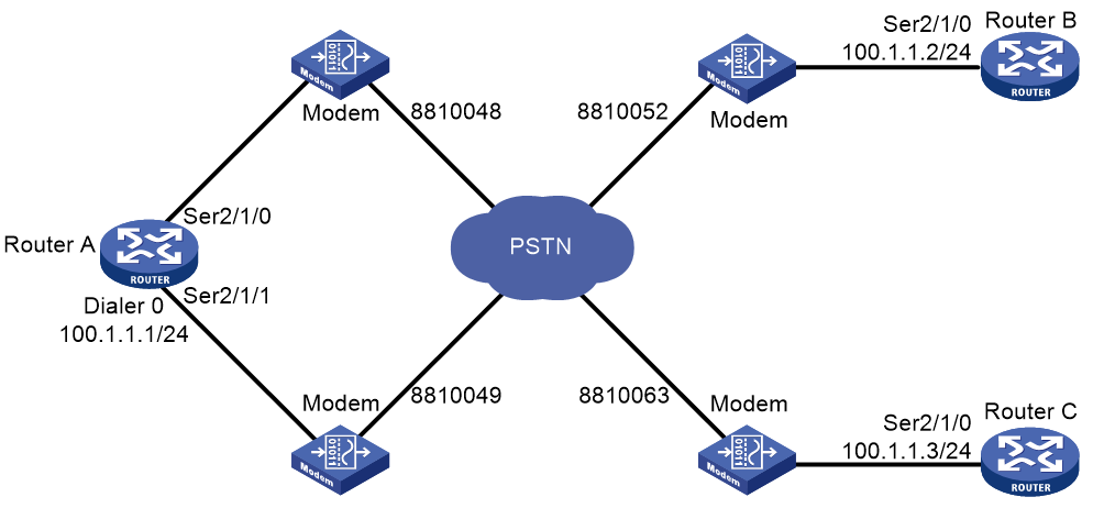
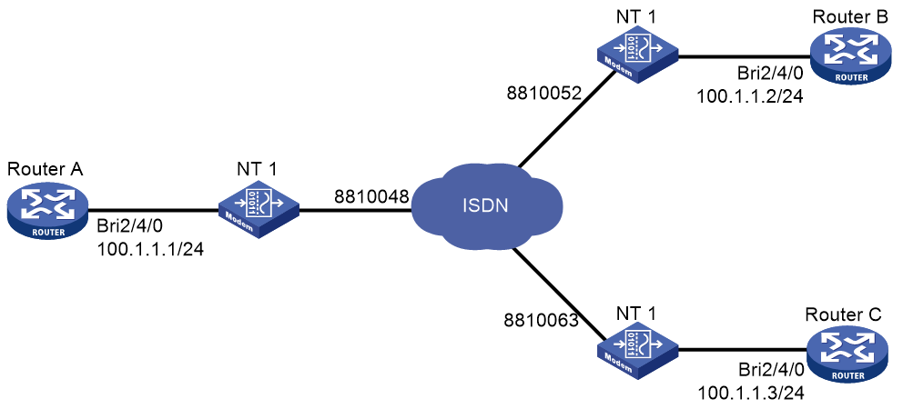
As shown in Figure 3, configure traditional DDR to meet the following requirements:
· Router A can call Router B and Router C from multiple interfaces.
· Router B and Router C cannot call each other.
Procedure
1. Configure Router A:
# Create dialer group 1 and configure a dial rule for it.
<RouterA> system-view
[RouterA] dialer-group 1 rule ip permit
# Enable traditional DDR on Dialer 0.
[RouterA] interface dialer 0
[RouterA-Dialer0] dialer circular enable
# Configure an IP address for Dialer 0.
[RouterA-Dialer0] ip address 100.1.1.1 255.255.255.0
# Associate dialer group 1 with Dialer 0.
[RouterA-Dialer0] dialer-group 1
# On Dialer 0, configure dial strings for calling Router B and Router C.
[RouterA-Dialer0] dialer route ip 100.1.1.2 dial-number 8810052
[RouterA-Dialer0] dialer route ip 100.1.1.3 dial-number 8810063
[RouterA-Dialer0] quit
# Configure Serial 2/1/0 to operate as an asynchronous interface in protocol mode.
[RouterA] interface serial 2/1/0
[RouterA-Serial2/1/0] physical-mode async
[RouterA-Serial2/1/0] async-mode protocol
# Assign Serial 2/1/0 to dialer circular group 0.
[RouterA-Serial2/1/0] dialer circular-group 0
[RouterA-Serial2/1/0] quit
# Configure Serial 2/1/1 to operate as an asynchronous interface in protocol mode.
[RouterA] interface serial 2/1/1
[RouterA-Serial2/1/1] physical-mode async
[RouterA-Serial2/1/1] async-mode protocol
# Assign Serial 2/1/1 to dialer circular group 0.
[RouterA-Serial2/1/1] dialer circular-group 0
[RouterA-Serial2/1/1] quit
# Configure user lines to be used, and enable modem dial-in and dial-out on them.
[RouterA] line tty1
[RouterA-line-tty1] modem enable both
[RouterA-line-tty1] quit
[RouterA] line tty2
[RouterA-line-tty2] modem enable both
2. Configure Router B:
# Create dialer group 1 and configure a dial rule for it.
<RouterB> system-view
[RouterB] dialer-group 1 rule ip permit
# Configure Serial 2/1/0 to operate as an asynchronous interface in protocol mode.
[RouterB] interface serial 2/1/0
[RouterB-Serial2/1/0] physical-mode async
[RouterB-Serial2/1/0] async-mode protocol
# Configure an IP address for Serial 2/1/0.
[RouterB-Serial2/1/0] ip address 100.1.1.2 255.255.255.0
# Enable traditional DDR on Serial 2/1/0.
[RouterB-Serial2/1/0] dialer circular enable
# Associate dialer group 1 with Serial 2/1/0.
[RouterB-Serial2/1/0] dialer-group 1
# On Serial 2/1/0, configure the dial strings for calling Router A.
[RouterB-Serial2/1/0] dialer route ip 100.1.1.1 dial-number 8810048
[RouterB-Serial2/1/0] dialer route ip 100.1.1.1 dial-number 8810049
[RouterB-Serial2/1/0] quit
# Configure the user line to be used, and enable modem dial-in and dial-out on it.
[RouterB] line tty1
[RouterB-line-tty1] modem enable both
3. Configure Router C:
# Create dialer group 1 and configure a dial rule for it.
<RouterC> system-view
[RouterC] dialer-group 1 rule ip permit
# Configure Serial 2/1/0 to operate as an asynchronous interface in protocol mode.
[RouterC] interface serial 2/1/0
[RouterC-Serial2/1/0] physical-mode async
[RouterC-Serial2/1/0] async-mode protocol
# Configure an IP address for Serial 2/1/0.
[RouterC-Serial2/1/0] ip address 100.1.1.3 255.255.255.0
# Enable traditional DDR on Serial 2/1/0.
[RouterC-Serial2/1/0] dialer circular enable
# Associate dialer group 1 with Serial 2/1/0.
[RouterC-Serial2/1/0] dialer-group 1
# On Serial 2/1/0, configure two dial strings for calling Router A.
[RouterC-Serial2/1/0] dialer route ip 100.1.1.1 dial-number 8810048
[RouterC-Serial2/1/0] dialer route ip 100.1.1.1 dial-number 8810049
[RouterC-Serial2/1/0] quit
# Configure the user line to be used, and enable modem dial-in and dial-out on it.
[RouterC] line tty1
[RouterC-line-tty1] modem enable both
Verifying the configuration
# Verify that Router A can successfully ping Router B and Router C. (Details not shown.)
# Verify that Router B and Router C cannot ping each other. (Details not shown.)
Example: Configuring PSTN-based bundle DDR
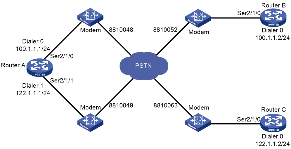
Network configuration
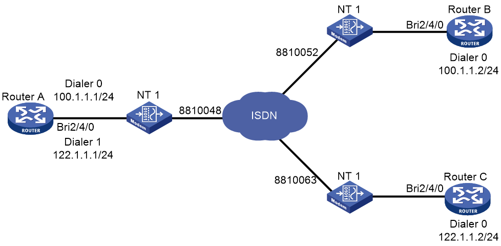
As shown in Figure 4:
· Dialer0 interfaces of Router A and Router B are in the same network segment.
· Dialer1 interface of Router A and the Dialer0 interface of Router C are in the same network segment.
Configure bundle DDR to meet the following requirements:
· Router A can call Router B and Router C from multiple interfaces.
· Router B and Router C cannot each other.
Procedure
1. Configure Router A:
# Create dialer group 1 and configure a dial rule for it.
<RouterA> system-view
[RouterA] dialer-group 1 rule ip permit
# Create local users userb and userc for authenticating Router B and Router C, and configure the service type as PPP for them.
[RouterA] local-user userb class network
[RouterA-luser-network-userb] password simple userb
[RouterA-luser-network-userb] service-type ppp
[RouterA-luser-network-userb] quit
[RouterA] local-user userc class network
[RouterA-luser-network-userc] password simple userc
[RouterA-luser-network-userc] service-type ppp
[RouterA-luser-network-userc] quit
# Configure an IP address for Dialer 0.
[RouterA] interface dialer 0
[RouterA-Dialer0] ip address 100.1.1.1 255.255.255.0
# Enable bundle DDR on Dialer 0.
[RouterA-Dialer0] dialer bundle enable
# On Dialer 0, specify the host name of the remote router allowed to call in.
[RouterA-Dialer0] dialer peer-name userb
# Associate Dialer 0 with dialer group 1.
[RouterA-Dialer0] dialer-group 1
# Configure PAP authentication on Dialer 0.
[RouterA-Dialer0] ppp authentication-mode pap
[RouterA-Dialer0] ppp pap local-user usera password simple usera
# On Dialer 0, configure the dial string for calling Router B.
[RouterA-Dialer0] dialer number 8810052
[RouterA-Dialer0] quit
# Configure an IP address for Dialer 1.
[RouterA] interface dialer 1
[RouterA-Dialer1] ip address 122.1.1.1 255.255.255.0
# Enable bundle DDR on Dialer 1.
[RouterA-Dialer1] dialer bundle enable
# On Dialer 1, specify the host name of the remote router allowed to call in.
[RouterA-Dialer1] dialer peer-name userc
# Associate Dialer 1 with dialer group 1.
[RouterA-Dialer1] dialer-group 1
# Configure PAP authentication on Dialer 1.
[RouterA-Dialer1] ppp authentication-mode pap
[RouterA-Dialer1] ppp pap local-user usera password simple usera
# On Dialer 1, configure the dial string for calling Router C.
[RouterA-Dialer1] dialer number 8810063
[RouterA-Dialer1] quit
# Configure Serial 2/1/0 as an asynchronous interface in protocol mode.
[RouterA] interface serial 2/1/0
[RouterA-Serial2/1/0] physical-mode async
[RouterA-Serial2/1/0] async-mode protocol
# Assign Serial 2/1/0 to Dialer 0 and Dialer 1.
[RouterA-Serial2/1/0] dialer bundle-member 0
[RouterA-Serial2/1/0] dialer bundle-member 1
# Enable PPP encapsulation on Serial 2/1/0.
[RouterA-Serial2/1/0] link-protocol ppp
# Configure PAP authentication on Serial 2/1/0.
[RouterA-Serial2/1/0] ppp authentication-mode pap
[RouterA-Serial2/1/0] ppp pap local-user usera password simple usera
[RouterA-Serial2/1/0] quit
# Configure Serial 2/1/1 as an asynchronous interface in protocol mode.
[RouterA] interface serial 2/1/1
[RouterA-Serial2/1/1] physical-mode async
[RouterA-Serial2/1/1] async-mode protocol
# Assign Serial 2/1/1 to Dialer 0 and Dialer 1.
[RouterA-Serial2/1/1] dialer bundle-member 0
[RouterA-Serial2/1/1] dialer bundle-member 1
# Enable PPP encapsulation on Serial 2/1/1.
[RouterA-Serial2/1/1] link-protocol ppp
# Configure PAP authentication on Serial 2/1/1.
[RouterA-Serial2/1/1] ppp authentication-mode pap
[RouterA-Serial2/1/1] ppp pap local-user usera password simple usera
[RouterA-Serial2/1/1] quit
# Configure user lines to be used, and enable modem dial-in and dial-out on them.
[RouterA] line tty1
[RouterA-line-tty1] modem enable both
[RouterA-line-tty1] quit
[RouterA] line tty2
[RouterA-line-tty2] modem enable both
2. Configure Router B:
# Create dialer group 2 and configure a dial rule for it.
<RouterB> system-view
[RouterB] dialer-group 2 rule ip permit
# Create local user usera for authenticating Router A, and configure the service type as PPP.
[RouterB] local-user usera class network
[RouterB-luser-network-usera] password simple usera
[RouterB-luser-network-usera] service-type ppp
[RouterB-luser-network-usera] quit
# Configure an IP address for Dialer 0.
[RouterB] interface dialer 0
[RouterB-Dialer0] ip address 100.1.1.2 255.255.255.0
# Enable bundle DDR on Dialer 0.
[RouterB-Dialer0] dialer bundle enable
# On Dialer 0, specify the host name of the remote router allowed to call in.
[RouterB-Dialer0] dialer peer-name usera
# On Dialer 0, configure the dial string for calling Serial 2/1/0 on Router A.
[RouterB-Dialer0] dialer number 8810048
# Associate Dialer 0 with dialer group 2.
[RouterB-Dialer0] dialer-group 2
# Configure PAP authentication on Dialer 0.
[RouterB-Dialer0] ppp authentication-mode pap
[RouterB-Dialer0] ppp pap local-user userb password simple userb
[RouterB-Dialer0] quit
# Configure Serial 2/1/0 as an asynchronous interface in protocol mode.
[RouterB] interface serial 2/1/0
[RouterB-Serial2/1/0] physical-mode async
[RouterB-Serial2/1/0] async-mode protocol
# Assign Serial 2/1/0 to Dialer 0.
[RouterB-Serial2/1/0] dialer bundle-member 0
# Enable PPP encapsulation on Serial 2/1/0.
[RouterB-Serial2/1/0] link-protocol ppp
# Configure PAP authentication on Serial 2/1/0.
[RouterB-Serial2/1/0] ppp authentication-mode pap
[RouterB-Serial2/1/0] ppp pap local-user userb password simple userb
[RouterB-Serial2/1/0] quit
# Configure the user line to be used, and enable modem dial-in and dial-out on it.
[RouterB] line tty1
[RouterB-line-tty1] modem enable both
3. Configure Router C:
# Create dialer group 1 and configure a dial rule for it.
<RouterC> system-view
[RouterC] dialer-group 1 rule ip permit
# Create local user usera for authenticating Router A, and configure the service type as PPP.
[RouterC] local-user usera class network
[RouterC-luser-network-usera] password simple usera
[RouterC-luser-network-usera] service-type ppp
[RouterC-luser-network-usera] quit
# Configure an IP address for Dialer 0.
[RouterC] interface dialer 0
[RouterC-Dialer0] ip address 122.1.1.2 255.255.255.0
# Enable bundle DDR on Dialer 0.
[RouterC-Dialer0] dialer bundle enable
# On Dialer 0, specify the host name of the remote router allowed to call in.
[RouterC-Dialer0] dialer peer-name usera
# On Dialer 0, configure the dial string for calling Serial 2/1/1 on Router A.
[RouterC-Dialer0] dialer number 8810049
# Associate Dialer 0 with dialer group 1.
[RouterC-Dialer0] dialer-group 1
# Configure PAP authentication on Dialer 0.
[RouterC-Dialer0] ppp authentication-mode pap
[RouterC-Dialer0] ppp pap local-user userc password simple userc
[RouterC-Dialer0] quit
# Configure Serial 2/1/0 as an asynchronous interface in protocol mode.
[RouterC] interface serial 2/1/0
[RouterC-Serial2/1/0] physical-mode async
[RouterC-Serial2/1/0] async-mode protocol
# Assign Serial 2/1/0 to Dialer 0.
[RouterC-Serial2/1/0] dialer bundle-member 0
# Enable PPP encapsulation on Serial 2/1/0.
[RouterC-Serial2/1/0] link-protocol ppp
# Configure PAP authentication on Serial 2/1/0.
[RouterC-Serial2/1/0] ppp authentication-mode pap
[RouterC-Serial2/1/0] ppp pap local-user userc password simple userc
[RouterC-Serial2/1/0] quit
# Configure the user line to be used, and enable modem dial-in and dial-out on it.
[RouterC] line tty1
[RouterC-line-tty1] modem enable both
Verifying the configuration
# Verify that Router A can successfully ping Router B and Router C. (Details not shown.)
# Verify that Router B and Router C cannot ping each other. (Details not shown.)
Example: Configuring ISDN-based traditional DDR
Network configuration
As shown in Figure 5, the interfaces BRI 2/4/0 of Router A, Router B, and Router C are in the same network segment.
Configure traditional DDR to meet the following requirements:
· Allow Router A to call Router B and Router C from multiple interfaces.
· Disable Router B and Router C from calling each other.
Procedure
1. Configure Router A:
# Create dialer group 1 and configure a dial rule for it.
<RouterA> system-view
[RouterA] dialer-group 1 rule ip permit
# Configure an IP address for BRI 2/4/0.
[RouterA] interface bri 2/4/0
[RouterA-Bri2/4/0] ip address 100.1.1.1 255.255.255.0
# Enable traditional DDR on BRI 2/4/0.
[RouterA-Bri2/4/0] dialer circular enable
# Associate BRI 2/4/0 with dialer group 1.
[RouterA-Bri2/4/0] dialer-group 1
# On BRI 2/4/0, configure the dial strings for calling Router B and Router C.
[RouterA-Bri2/4/0] dialer route ip 100.1.1.2 dial-number 8810052
[RouterA-Bri2/4/0] dialer route ip 100.1.1.3 dial-number 8810063
2. Configure Router B:
# Create dialer group 2 and configure a dial rule for it.
<RouterB> system-view
[RouterB] dialer-group 2 rule ip permit
# Configure an IP address for BRI 2/4/0.
[RouterB] interface bri 2/4/0
[RouterB-Bri2/4/0] ip address 100.1.1.2 255.255.255.0
# Enable traditional DDR on BRI 2/4/0.
[RouterB-Bri2/4/0] dialer circular enable
# Associate BRI 2/4/0 with dialer group 2.
[RouterB-Bri2/4/0] dialer-group 2
# On BRI 2/4/0, configure the dial string for calling Router A.
[RouterB-Bri2/4/0] dialer route ip 100.1.1.1 dial-number 8810048
3. Configure Router C:
# Create dialer group 1 and configure a dial rule for it.
<RouterC> system-view
[RouterC] dialer-group 1 rule ip permit
# Configure an IP address for BRI 2/4/0.
[RouterC] interface bri 2/4/0
[RouterC-Bri2/4/0] ip address 100.1.1.3 255.255.255.0
# Enable traditional DDR on BRI 2/4/0.
[RouterC-Bri2/4/0] dialer circular enable
# Associate BRI 2/4/0 with dialer group 1.
[RouterC-Bri2/4/0] dialer-group 1
# On BRI 2/4/0, configure the dial string for calling Router A.
[RouterC-Bri2/4/0] dialer route ip 100.1.1.1 dial-number 8810048
Verifying the configuration
# Verify that Router A can successfully ping Router B and Router C. (Details not shown.)
# Verify that Router B and Router C cannot ping each other. (Details not shown.)
Example: Configuring ISDN-based bundle DDR
Network configuration
As shown in Figure 6, the interfaces BRI 2/4/0 of Router A, Router B, and Router C are in the same network segment.
Configure bundle DDR to meet the following requirements:
· Allow Router A to call Router B and Router C from multiple interfaces.
· Disable Router B and Router C from calling each other.
Procedure
1. Configure Router A:
# Create dialer group 1 and configure a dial rule for it.
<RouterA> system-view
[RouterA] dialer-group 1 rule ip permit
# Create local users userb and userc for authenticating Router B and Router C, and configure the service type as PPP for them.
[RouterA] local-user userb class network
[RouterA-luser-network-userb] password simple userb
[RouterA-luser-network-userb] service-type ppp
[RouterA-luser-network-userb] quit
[RouterA] local-user userc class network
[RouterA-luser-network-userc] password simple userc
[RouterA-luser-network-userc] service-type ppp
[RouterA-luser-network-userc] quit
# Configure an IP address for Dialer 0.
[RouterA] interface dialer 0
[RouterA-Dialer0] ip address 100.1.1.1 255.255.255.0
# Enable bundle DDR on Dialer 0.
[RouterA-Dialer0] dialer bundle enable
# On Dialer 0, specify the host name of the remote router allowed to call in.
[RouterA-Dialer0] dialer peer-name userb
# Associate Dialer 0 with dialer group 1.
[RouterA-Dialer0] dialer-group 1
# Configure PAP authentication on Dialer 0.
[RouterA-Dialer0] ppp authentication-mode pap
[RouterA-Dialer0] ppp pap local-user usera password simple usera
# On Dialer 0, configure the dial string for calling Router B.
[RouterA-Dialer0] dialer number 8810052
[RouterA-Dialer0] quit
# Configure an IP address for Dialer 1.
[RouterA] interface dialer 1
[RouterA-Dialer1] ip address 122.1.1.1 255.255.255.0
# Enable bundle DDR on Dialer 1.
[RouterA-Dialer1] dialer bundle enable
# On Dialer 1, specify the host name of the remote router allowed to call in.
[RouterA-Dialer1] dialer peer-name userc
# Associate Dialer 1 with dialer group 1.
[RouterA-Dialer1] dialer-group 1
# Configure PAP authentication on Dialer 1.
[RouterA-Dialer1] ppp authentication-mode pap
[RouterA-Dialer1] ppp pap local-user usera password simple usera
# On Dialer 1, configure the dial string for calling Router C.
[RouterA-Dialer1] dialer number 8810063
[RouterA-Dialer1] quit
# Assign BRI 2/4/0 to dialer bundle 0 and dialer bundle 1.
[RouterA] interface bri 2/4/0
[RouterA-Bri2/4/0] dialer bundle-member 0
[RouterA-Bri2/4/0] dialer bundle-member 1
# Enable PPP encapsulation on BRI 2/4/0.
[RouterA-Bri2/4/0] link-protocol ppp
# Configure PAP authentication on BRI 2/4/0.
[RouterA-Bri2/4/0] ppp authentication-mode pap
[RouterA-Bri2/4/0] ppp pap local-user usera password simple usera
2. Configure Router B:
# Create dialer group 2 and configure a dial rule for it.
<RouterB> system-view
[RouterB] dialer-group 2 rule ip permit
# Create local user usera for authenticating Router A, and configure the service type as PPP.
[RouterB] local-user usera class network
[RouterB-luser-network-usera] password simple usera
[RouterB-luser-network-usera] service-type ppp
[RouterB-luser-network-usera] quit
# Configure an IP address for Dialer 0.
[RouterB] interface dialer 0
[RouterB-Dialer0] ip address 100.1.1.2 255.255.255.0
# Enable bundle DDR on Dialer 0.
[RouterB-Dialer0] dialer bundle enable
# On Dialer 0, specify the host name of the remote router allowed to call in.
[RouterB-Dialer0] dialer peer-name usera
# Associate Dialer 0 with dialer group 2.
[RouterB-Dialer0] dialer-group 2
# Configure PAP authentication on Dialer 0.
[RouterB-Dialer0] ppp authentication-mode pap
[RouterB-Dialer0] ppp pap local-user userb password simple userb
# On Dialer 0, configure the dial string for calling Router A.
[RouterB-Dialer0] dialer number 8810048
[RouterB-Dialer0] quit
# Assign BRI 2/4/0 to dialer bundle 0.
[RouterB] interface bri 2/4/0
[RouterB-Bri2/4/0] dialer bundle-member 0
# Enable PPP encapsulation on BRI 2/4/0.
[RouterB-Bri2/4/0] link-protocol ppp
# Configure PAP authentication on BRI 2/4/0.
[RouterB-Bri2/4/0] ppp authentication-mode pap
[RouterB-Bri2/4/0] ppp pap local-user userb password simple userb
3. Configure Router C:
# Create dialer group 1 and configure a dial rule for it.
<RouterC> system-view
[RouterC] dialer-group 1 rule ip permit
# Create local user usera for authenticating Router A, and configure the service type as PPP.
[RouterC] local-user usera class network
[RouterC-luser-network-usera] password simple usera
[RouterC-luser-network-usera] service-type ppp
[RouterC-luser-network-usera] quit
# Configure an IP address for Dialer 0.
[RouterC] interface dialer 0
[RouterC-Dialer0] ip address 122.1.1.2 255.255.255.0
# Enable bundle DDR on Dialer 0.
[RouterC-Dialer0] dialer bundle enable
# On Dialer 0, specify the host name of the remote router allowed to call in.
[RouterC-Dialer0] dialer peer-name usera
# Associate Dialer 0 with dialer group 1.
[RouterC-Dialer0] dialer-group 1
# On Dialer 0, configure the dial string for calling Router A.
[RouterC-Dialer0] dialer number 8810048
# Configure PAP authentication on Dialer 0.
[RouterC-Dialer0] ppp authentication-mode pap
[RouterC-Dialer0] ppp pap local-user userc password simple userc
[RouterC-Dialer0] quit
# Assign BRI 2/4/0 to dialer bundle 0.
[RouterC] interface bri 2/4/0
[RouterC-Bri2/4/0] dialer bundle-member 0
# Enable PPP encapsulation on BRI 2/4/0.
[RouterC-Bri2/4/0] link-protocol ppp
# Configure PAP authentication on BRI 2/4/0.
[RouterC-Bri2/4/0] ppp authentication-mode pap
[RouterC-Bri2/4/0] ppp pap local-user userc password simple userc
Verifying the configuration
# Verify that Router A can successfully ping Router B and Router C. (Details not shown.)
# Verify that Router B and Router C cannot ping each other. (Details not shown.)
Example: Configuring MP for DDR
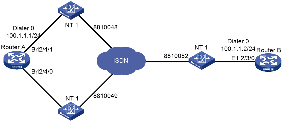
Network configuration
As shown in Figure 7, two ISDN BRI interfaces on Router A and an ISDN PRI interface on Router B are connected across ISDN.
Configure Router A to call Router B by using bundle DDR, and configure Router B to call Router A by using traditional DDR. In addition, implement traffic distribution for the two interfaces on Router A by setting traffic thresholds.
Procedure
1. Configure Router A:
# Create dialer group 1 and configure a dial rule for it.
<RouterA> system-view
[RouterA] dialer-group 1 rule ip permit
# Create local user userb for authenticating Router B, and configure the service type as PPP.
[RouterA] local-user userb class network
[RouterA-luser-network-userb] password simple userb
[RouterA-luser-network-userb] service-type ppp
[RouterA-luser-network-userb] quit
# Set the traffic statistics collection interval to 3 seconds.
[RouterA] dialer flow-interval 3
# Configure an IP address for Dialer 0, enable bundle DDR, and configure MP.
[RouterA] interface dialer 0
[RouterA-Dialer0] ip address 100.1.1.1 255.255.255.0
[RouterA-Dialer0] dialer bundle enable
[RouterA-Dialer0] ppp mp
[RouterA-Dialer0] dialer threshold 50
# On Dialer 0, specify the host name of the remote router allowed to call in.
[RouterA-Dialer0] dialer peer-name userb
# Associate Dialer 0 with dialer group 1.
[RouterA-Dialer0] dialer-group 1
# Configure PAP authentication on Dialer 0.
[RouterA-Dialer0] ppp authentication-mode pap
[RouterA-Dialer0] ppp pap local-user usera password simple usera
# On Dialer 0, configure the dial string for calling Router B.
[RouterA-Dialer0] dialer number 8810052
[RouterA-Dialer0] quit
# Assign BRI 2/4/1 to dialer bundle 0.
[RouterA] interface bri 2/4/1
[RouterA-Bri2/4/1] dialer bundle-member 0
# Enable MP for BRI 2/4/1.
[RouterA-Bri2/4/1] ppp mp
# Enable PPP encapsulation on BRI 2/4/1.
[RouterA-Bri2/4/1] link-protocol ppp
# Configure PAP authentication on BRI 2/4/1.
[RouterA-Bri2/4/1] ppp authentication-mode pap
[RouterA-Bri2/4/1] ppp pap local-user usera password simple usera
[RouterA-Bri2/4/1] quit
# Configure PPP authentication on BRI 2/4/0, and assign BRI 2/4/0 to dialer bundle 0.
[RouterA-Bri2/4/0] interface bri 2/4/0
[RouterA-Bri2/4/0] dialer bundle-member 0
# Enable MP for BRI 2/4/0.
[RouterA-Bri2/4/0] ppp mp
# Enable PPP encapsulation on BRI 2/4/0.
[RouterA-Bri2/4/0] link-protocol ppp
# Configure PAP authentication on BRI 2/4/0.
[RouterA-Bri2/4/0] ppp authentication-mode pap
[RouterA-Bri2/4/0] ppp pap local-user usera password simple usera
# Create dialer group 2 and configure a dial rule for it.
<RouterB> system-view
[RouterB] dialer-group 2 rule ip permit
# Create local user usera for authenticating Router A, and configure the service type as PPP.
[RouterB] local-user usera class network
[RouterB-luser-network-usera] password simple usera
[RouterB-luser-network-usera] service-type ppp
[RouterB-luser-network-usera] quit
# Set the traffic statistics collection interval to 3 seconds.
[RouterB] dialer flow-interval 3
# Configure an IP address for Dialer 0.
[RouterB] interface dialer 0
[RouterB-Dialer0] ip address 100.1.1.2 255.255.255.0
# Enable traditional DDR on Dialer 0.
[RouterB-Dialer0] dialer circular enable
# Associate Dialer 0 with dialer group 2.
[RouterB-Dialer0] dialer-group 2
# On Dialer 0, configure the dial strings for calling Router A.
[RouterB-Dialer0] dialer route ip 100.1.1.1 dial-number 8810048
[RouterB-Dialer0] dialer route ip 100.1.1.1 dial-number 8810049
# Enable MP for Dialer 0.
[RouterB-Dialer0] ppp mp
# Configure PAP authentication on Dialer 0.
[RouterB-Dialer0] ppp authentication-mode pap
[RouterB-Dialer0] ppp pap local-user userb password simple userb
[RouterB-Dialer0] quit
# Bundle timeslots on CE1/PRI interface E1 2/3/0 into a PRI group.
[RouterB] controller e1 2/3/0
[RouterB-E1 2/3/0] pri-set
[RouterB-E1-2/3/0] quit
# Assign Serial 2/3/0:15 created on E1 2/3/0 to dialer circular group 0, which is associated with Dialer 0.
[RouterB] interface serial 2/3/0:15
[RouterB-Serial2/3/0:15] dialer circular-group 0
Example: Configuring ISDN caller number callback
Network configuration
As shown in Figure 8, configure ISDN caller number callback on Router A and Router B by using traditional DDR. Then, Router B can make a return call by using an ISDN caller number when Router A calls Router B.

|
|
NOTE: Make sure the stored program controlled switch (SPCS) in the ISDN network supports sending ISDN calling numbers. |
Procedure
1. Configure Router A:
# Create dialer group 1 and configure a dial rule for it.
<RouterA> system-view
[RouterA] dialer-group 1 rule ip permit
# Configure an IP address for BRI 2/4/0.
[RouterA] interface bri 2/4/0
[RouterA-Bri2/4/0] ip address 100.1.1.1 255.255.255.0
# Enable traditional DDR on BRI 2/4/0.
[RouterA-Bri2/4/0] dialer circular enable
# Associate BRI 2/4/0 with dialer group 1.
[RouterA-Bri2/4/0] dialer-group 1
# On BRI 2/4/0, configure the dial string for calling Router B.
[RouterA-Bri2/4/0] dialer route ip 100.1.1.2 dial-number 8810052
# Set the holddown timer to 15 seconds on BRI 2/4/0.
[RouterA-Bri2/4/0] dialer timer enable 15
# Configure BRI 2/4/0 to carry ISDN calling number 8810048 in the message sent to the called party.
[RouterA-Bri2/4/0] isdn calling 8810048
2. Configure Router B:
# Create dialer group 2 and configure a dial rule for it.
<RouterB> system-view
[RouterB] dialer-group 2 rule ip permit
# Configure an IP address to BRI 2/4/0.
[RouterB] interface bri 2/4/0
[RouterB-Bri2/4/0] ip address 100.1.1.2 255.255.255.0
# Enable traditional DDR on BRI 2/4/0.
[RouterB-Bri2/4/0] dialer circular enable
# Associate BRI 2/4/0 with dialer group 2.
[RouterB-Bri2/4/0] dialer-group 2
# On BRI 2/4/0, configure the dial string for calling Router A.
[RouterB-Bri2/4/0] dialer route ip 100.1.1.1 dial-number 8810048
# Enable BRI 2/4/0 to place return calls for ISDN calling number 8810048.
[RouterB-Bri2/4/0] dialer call-in 8810048 callback
Example: Configuring Router-to-router PPP callback
Network configuration
As shown in Figure 9, configure PPP callback for traditional DDR, so that when Router A calls Router B, Router B can make a return call.

Procedure (Method 1)
Use the dial string configured in the dialer route command to call back the client.
1. Configure Router A:
# Create dialer group 1 and configure a dial rule for it.
<RouterA> system-view
[RouterA] dialer-group 1 rule ip permit
# Configure an IP address for Serial 2/1/0.
[RouterA] interface serial 2/1/0
[RouterA-Serial2/1/0] ip address 100.1.1.1 255.255.255.0
# Configure Serial 2/1/0 as an asynchronous interface in protocol mode.
[RouterA-Serial2/1/0] physical-mode async
[RouterA-Serial2/1/0] async-mode protocol
# Enable traditional DDR on Serial 2/1/0.
[RouterA-Serial2/1/0] dialer circular enable
# Associate Serial 2/1/0 with dialer group 1.
[RouterA-Serial2/1/0] dialer-group 1
# On Serial 2/1/0, configure the dial string for calling Router B.
[RouterA-Serial2/1/0] dialer route ip 100.1.1.2 dial-number 8810052
# Enable PPP encapsulation on Serial 2/1/0.
[RouterA-Serial2/1/0] link-protocol ppp
# Configure PAP authentication on Serial 2/1/0.
[RouterA-Serial2/1/0] ppp pap local-user usera password simple usera
# Enable Serial 2/1/0 to initiate callback requests as the callback client.
[RouterA-Serial2/1/0] ppp callback client
# Set the holddown timer to 15 seconds on Serial 2/1/0.
[RouterA-Serial2/1/0] dialer timer enable 15
[RouterA-Serial2/1/0] quit
# Configure the user line to be used, and enable modem dial-in and dial-out on it.
[RouterA-line-tty1] modem enable both
2. Configure Router B:
# Create dialer group 2 and configure a dial rule for it.
[RouterB] dialer-group 2 rule ip permit
# Create local user usera for authenticating Router A, and configure the service type as PPP.
[RouterB] local-user usera class network
[RouterB-luser-network-usera] password simple usera
[RouterB-luser-network-usera] service-type ppp
[RouterB-luser-network-usera] quit
# Configure an IP address for Serial 2/1/0.
[RouterB] interface serial 2/1/0
[RouterB-Serial2/1/0] ip address 100.1.1.2 255.255.255.0
# Configure Serial 2/1/0 as an asynchronous interface in protocol mode.
[RouterB-Serial2/1/0] physical-mode async
[RouterB-Serial2/1/0] async-mode protocol
# Enable traditional DDR on Serial 2/1/0.
[RouterB-Serial2/1/0] dialer circular enable
# Associate Serial 2/1/0 with dialer group 2.
[RouterB-Serial2/1/0] dialer-group 2
# Enable PPP encapsulation on Serial 2/1/0.
[RouterB-Serial2/1/0] link-protocol ppp
# Enable PAP authentication on Serial 2/1/0.
[RouterB-Serial2/1/0] ppp authentication-mode pap
# Enable Serial 2/1/0 to accept callback requests as the callback server.
[RouterB-Serial2/1/0] ppp callback server
# Configure Serial 2/1/0 to use the dial string configured in the dialer route command to call back.
[RouterB-Serial2/1/0] dialer callback-center user
# On Serial 2/1/0, configure the dial string for callback.
[RouterB-Serial2/1/0] dialer route ip 100.1.1.1 dial-number 8810048 user usera
[RouterB-Serial2/1/0] quit
# Configure the user line to be used, and enable modem dial-in and dial-out on it.
[RouterB-line-tty2] modem enable both
Procedure (Method 2)
Use the callback number configured in the authorization-attribute callback-number command to call back the client.
1. Configure Router A:
# Create dialer group 1 and configure a dial rule for it.
<RouterA> system-view
[RouterA] dialer-group 1 rule ip permit
# Configure an IP address for Serial 2/1/0.
[RouterA] interface serial 2/1/0
[RouterA-Serial2/1/0] ip address 100.1.1.1 255.255.255.0
# Configure Serial 2/1/0 as an asynchronous interface in protocol mode.
[RouterA-Serial2/1/0] physical-mode async
[RouterA-Serial2/1/0] async-mode protocol
# Enable traditional DDR on Serial 2/1/0.
[RouterA-Serial2/1/0] dialer circular enable
# Associate Serial 2/1/0 with dialer group 1.
[RouterA-Serial2/1/0] dialer-group 1
# On Serial 2/1/0, configure the dial string for calling Router B.
[RouterA-Serial2/1/0] dialer route ip 100.1.1.2 dial-number 8810052
# Enable PPP encapsulation on Serial 2/1/0.
[RouterA-Serial2/1/0] link-protocol ppp
# Configure PAP authentication on Serial 2/1/0.
[RouterA-Serial2/1/0] ppp pap local-user usera password simple usera
# Enable Serial 2/1/0 to initiate callback requests as the callback client.
[RouterA-Serial2/1/0] ppp callback client
# Set the holddown timer to 15 seconds on Serial 2/1/0.
[RouterA-Serial2/1/0] dialer timer enable 15
[RouterA-Serial2/1/0] quit
# Configure the user line to be used, and enable modem dial-in and dial-out on it.
[RouterA] line tty1
[RouterA-line-tty1] modem enable both
2. Configure Router B:
# Create dialer group 2 and configure a dial rule for it.
[RouterB] dialer-group 2 rule ip permit
# Create local user usera for authenticating Router A, and configure the service type as PPP.
[RouterB] local-user usera class network
[RouterB-luser-network-usera] password simple usera
[RouterB-luser-network-usera] service-type ppp
# Configure the dial string for callback.
[RouterB-luser-network-usera] authorization-attribute callback-number 8810048
[RouterB-luser-network-usera] quit
# Configure an IP address for Serial 2/1/0.
[RouterB] interface serial 2/1/0
[RouterB-Serial2/1/0] ip address 100.1.1.2 255.255.255.0
# Configure Serial 2/1/0 as an asynchronous interface in protocol mode.
[RouterB-Serial2/1/0] physical-mode async
[RouterB-Serial2/1/0] async-mode protocol
# Enable traditional DDR on Serial 2/1/0.
[RouterB-Serial2/1/0] dialer circular enable
# Associate Serial 2/1/0 with dialer group 2.
[RouterB-Serial2/1/0] dialer-group 2
# Enable PPP encapsulation on Serial 2/1/0.
[RouterB-Serial2/1/0] link-protocol ppp
# Enable PAP authentication on Serial 2/1/0.
[RouterB-Serial2/1/0] ppp authentication-mode pap
# Enable Serial 2/1/0 to accept callback requests as the callback server.
[RouterB-Serial2/1/0] ppp callback server
# Configure Serial 2/1/0 to use the dial string configured in the dialer callback-center dial-number command to call back.
[RouterB-Serial2/1/0] dialer callback-center dial-number
[RouterB-Serial2/1/0] quit
# Configure the user line to be used, and enable modem dial-in and dial-out on it.
[RouterB] line tty2
[RouterB-line-tty2] modem enable both
Example: Configuring Router-to-PC PPP callback
Network configuration
As shown in Figure 10, the PC obtains its IP address from the router through PPP.
Configure PPP callback for traditional DDR between the router and the PC. Then, the router can use the specified dial string to make a return call when the PC calls the router.

Procedure for configuring the PC (installed with Windows XP for example)
To create a dialup connection with callback capability enabled:
1. Place the modem connected to PC in auto answer mode.
2. Select Start > Programs > Accessories > Communications > Network and Dial-up Connections.
The Network and Dial-up Connections window appears.
3. Right-click the Make New Connection icon, and select New Connection… from the shortcut menu.
The Network Connection Wizard window appears.
4. Click Next.
The Network Connection Type dialog box appears.
5. Select the Dial-up to the Internet option, and click Next.
The Internet Connection Wizard dialog appears.
6. Select I want to set up my Internet connection manually or I want to connect through a local area network. Click Next.
The Setting up your Internet connection dialog box appears.
7. Select the I connect through a phone line and a modem option, and click Next.
8. Enter the phone number for dialing to the callback server, and click Next.
9. Enter the username and password that you want to use for PPP authentication when connecting to the server, and click Next.
10. Assign a name to your new connection and follow the instruction to complete the connection establishment.
11. Open the Network and Dial-up Connections window, right-click the connection you created, and select the Properties option in the popup menu.
The properties setting dialog box appears.
12. Click the Networking tab. On the Type of dial-up server I am calling list, select PPP: Windows 95/98/NT4/2000, Internet. Click Settings and perform the following tasks:
a. Select the Enable LCP extensions box.
b. Clear the Enable software compression box.
c. Clear the Negotiate multi-link for single link connections box.
d. Click OK.
13. In the Network and Dial-up Connections window, click the connection icon you created. Then, from the menu bar, select Advanced > Dial-up Preferences. In the Dial-up Preferences dialog box, click the Callback tab and perform one of the following tasks:
¡ Select the No callback option.
After the PPP authentication is passed in a call, this option prevents the callback server from disconnecting the current connection and calling back. Instead, the server will maintain the current connection and allow the client to access the LAN or the Internet.
¡ Select the Ask me during dialing when the server offers option.
The callback server will use the callback number you entered to place return calls.
¡ Select the Always call me back at the number(s) below option.
The callback server will always place return calls at the number or numbers already set.
Procedure for configuring the router
# Create dialer group 1 and configure a dial rule for it.
<Router> system-view
[Router] dialer-rule 1 ip permit
# Create local user userpc for the PC, and configure the service type as PPP.
[Router] local-user userpc
[Router-luser-userpc] password simple userpc
[Router-luser-userpc] service-type ppp
[Router-luser-userpc] quit
# Configure an IP address for Serial 2/1/0.
[Router] interface serial 2/1/0
[Router-Serial2/1/0] ip address 100.1.1.1 255.255.255.0
# Configure Serial 2/1/0 as an asynchronous interface in protocol mode.
[Router-Serial2/1/0] physical-mode async
[Router-Serial2/1/0] async mode protocol
# Enable PPP encapsulation on Serial 2/1/0.
[Router-Serial2/1/0] link-protocol ppp
# Configure PAP authentication on Serial 2/1/0.
[Router-Serial2/1/0] ppp authentication-mode pap
[Router-Serial2/1/0] ppp pap local-user Router password simple Router
# Configure Serial 2/1/0 to assign an IP address to the peer.
[Router-Serial2/1/0] remote address 100.1.1.2
# Enable Serial 2/1/0 to accept callback requests as the callback server.
[Router-Serial2/1/0] ppp callback server
# Configure Serial 2/1/0 to use the dial string configured in the dialer route command to call back.
[Router-Serial2/1/0] dialer callback-center user
# Enable traditional DDR on Serial 2/1/0.
[Router-Serial2/1/0] dialer circular enable
# Associate Serial 2/1/0 with dialer group 1.
[Router-Serial2/1/0] dialer-group 1
# On Serial 2/1/0, configure the dial string for calling the PC.
[Router-Serial2/1/0] dialer route ip 100.1.1.2 dial-number 8810048 user userpc
[Router-Serial2/1/0] quit
# Configure the user line to be used, and enable modem dial-in and dial-out on it.
[Router] line tty1
[Router-line-tty1] modem enable both
Example: Configuring Windows server-to-router PPP callback
Network configuration
As shown in Figure 11, the router obtains its IP address from the Windows server through PPP.
Configure PPP callback for traditional DDR between the router and Windows server. Then, the Windows server can use the specified dial string to make a return call when the router calls the Windows server.

Procedure for configuring the router
# Create dialer group 1 and configure a dial rule for it.
<Router> system-view
[Router] dialer-group 1 rule ip permit
# Create local user userpc for the PC, and configure the service type as PPP.
[Router] local-user usernt class network
[Router-luser-network-userc] password simple usernt
[Router-luser-network-userc] service-type ppp
[Router-luser-network-userc] quit
# Configure Serial 2/1/0 as an asynchronous interface in protocol mode.
[Router] interface serial 2/1/0
[Router-Serial2/1/0] physical-mode async
[Router-Serial2/1/0] async-mode protocol
# Enable PPP encapsulation on Serial 2/1/0.
[Router-Serial2/1/0] link-protocol ppp
# Configure PAP authentication on Serial 2/1/0.
[Router-Serial2/1/0] ppp authentication-mode pap
[Router-Serial2/1/0] ppp pap local-user Router password simple Router
# Configure Serial 2/1/0 to obtain an IP address through PPP negotiation.
[Router-Serial2/1/0] ip address ppp-negotiate
# Enable Serial 2/1/0 to initiate callback requests as the callback client.
[Router-Serial2/1/0] ppp callback client
# Set the holddown timer to 15 seconds on Serial 2/1/0.
[Router-Serial2/1/0] dialer timer enable 15
# Enable traditional DDR on Serial 2/1/0.
[Router-Serial2/1/0] dialer circular enable
# Associate Serial 2/1/0 with dialer group 1.
[Router-Serial2/1/0] dialer-group 1
# On Serial 2/1/0, configure the dial string for calling the Windows server.
[Router-Serial2/1/0] dialer route ip 100.1.1.254 dial-number 8810052
[Router-Serial2/1/0] quit
# Configure the user line to be used, and enable modem dial-in and dial-out on it.
[Router] line tty1
[Router-line-tty1] modem enable both
Procedure for configuring the Windows server
For Microsoft Windows users, the server must be Windows 2000 or later such as Windows XP. This example uses Windows XP.
To create a dialup connection with callback capability enabled:
1. Right-click the My Network Places icon, and select the Properties option from the menu that appears.
The Network and Dial-up Connections window appears.
2. Right-click the Make New Connection icon, and select the New Connection…option from the menu that appears.
The Network Connection Wizard window appears.
3. Click Next.
The Network Connection Type dialog box appears.
4. Select Set up an advanced connection, and click Next.
5. Select the Accept incoming connections option, and click Next to set the devices for incoming connections. Click Next.
The Incoming Virtual Private Network (VPN) Connection window appears.
6. Select the Allow virtual private connections option if the server is connected to the Internet to provide Internet access requests for the client. Otherwise, select the Do not allow virtual private connections. Then click Next.
The User Permissions window appears. Set the usernames and passwords for the clients allowed to call back.
7. Click Add. In the New User dialog box that appears, add the username and password for the PPP callback client and click OK.
An icon for the new user account appears in the box in the User Permissions window.
8. Select the new user and click Properties.
The properties setting dialog appears.
9. On the Callback tab, perform one of the following tasks:
¡ Select the Do not allow callback option.
After the PPP authentication is passed in a call, this option prevents the callback server from disconnecting the current connection and calling back. Instead, the server will maintain the current connection and allow the client to access the LAN or the Internet.
¡ Select the Allow the caller to set the callback number option.
After the PPP authentication is passed in a call, the server will disconnect and then call back the client at the number configured in the ppp callback ntstring dial-number command. This option is the same as the last option except that the charges are paid by the server end instead of the client end.
¡ Select the Always use the following callback number option to set a callback number.
10. Click Next.
The Networking Software window appears.
11. Set the networking components, and use the default settings for the network protocols. Click Next.
12. Assign a name to your connection.
13. Click Finish to complete the creation.
Example: Configuring circular dial string backup and Internet access
Network configuration
As shown in Figure 12:
· Router B operates as an access server and is configured with an IP address of 100.1.1.254/24. It uses the address range of 100.1.1.1/24 to 100.1.1.16/24 for address assignment. The PSTN dial strings available on it are 8810048 through 8810055, allowing the router to provide services to 16 online users.
· Router A accepts the IP address assigned by Router B.
Configure Router A on the dialup side to implement cyclic dial string backup with dialer routes. Configure Router B on the access side to use asynchronous serial interfaces to provide DDR dialup access and adopt PAP to authenticate the dialup side.
As shown in Figure 13, Router C and Router D have the same configurations as Router A and Router B. The only difference is that Router D uses an ISDN dial string 8810048 rather than PSTN dial strings to provide services.
Configure Router C and Router D to implement DDR with one dial string and use CHAP for authentication.
Figure 12 Network diagram for dial string backup/Internet access service (PSTN mode)
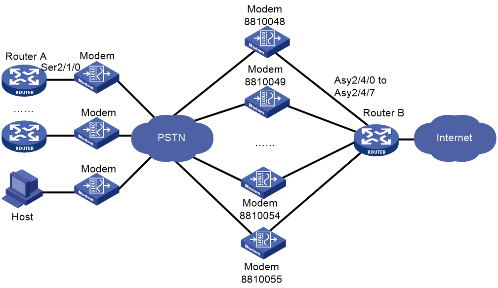
Figure 13 Network diagram for dial string backup/Internet access service (ISDN mode)
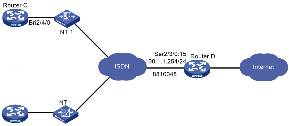
Procedure for PSTN mode
On Router A on the dialup side, configure circular dial string backup.
On Router B, perform the following tasks:
· Configure traditional DDR to allow the router to establish connections on eight asynchronous serial interfaces.
· Configure traditional DDR parameters on a dialer interface.
1. Configure Router A:
# Create dialer group 1 and configure a dial rule for it.
<RouterA> system-view
[RouterA] dialer-group 1 rule ip permit
# Create local user userb for authenticating Router B, and configure the service type as PPP.
[RouterA] local-user userb class network
[RouterA-luser-network-userb] password simple userb
[RouterA-luser-network-userb] service-type ppp
[RouterA-luser-network-userb] quit
# Configure Serial 2/1/0 as an asynchronous interface in protocol mode.
[RouterA] interface serial 2/1/0
[RouterA-Serial2/1/0] physical-mode async
[RouterA-Serial2/1/0] async-mode protocol
# Enable PPP address negotiation on Serial 2/1/0.
[RouterA-Serial2/1/0] ip address ppp-negotiate
# Enable PPP encapsulation on Serial 2/1/0.
[RouterA-Serial2/1/0] link-protocol ppp
# Configure PAP authentication on Serial 2/1/0.
[RouterA-Serial2/1/0] ppp authentication-mode pap
[RouterA-Serial2/1/0] ppp pap local-user user1 password simple user1
# Enable traditional DDR on Serial 2/1/0.
[RouterA-Serial2/1/0] dialer circular enable
# Associate Serial 2/1/0 with dialer group 1.
[RouterA-Serial2/1/0] dialer-group 1
# On Serial 2/1/0, configure the dial strings for calling Router B.
[RouterA-Serial2/1/0] dialer route ip 100.1.1.254 dial-number 8810048
[RouterA-Serial2/1/0] dialer route ip 100.1.1.254 dial-number 8810049
...
[RouterA-Serial2/1/0] dialer route ip 100.1.1.254 dial-number 8810055
[RouterA-Serial2/1/0] quit
# Configure the user line to be used, and enable modem dial-in and dial-out on it.
[RouterA] line tty1
[RouterA-line-tty1] modem enable both
2. Configure Router B:
# Create dialer group 2 and configure a dial rule for it.
<RouterB> system-view
[RouterB] dialer-group 2 rule ip permit
# Create local users user1 through user16 for authentication, and configure the service type as PPP for them.
[RouterB] local-user user1 class network
[RouterB-luser-network-user1] password simple user1
[RouterB-luser-network-user1] service-type ppp
[RouterB-luser-network-user1] quit
[RouterB] local-user user2 class network
[RouterB-luser-network-user2] password simple user2
[RouterB-luser-network-user2] service-type ppp
[RouterB-luser-network-user2] quit
...
[RouterB] local-user user16 class network
[RouterB-luser-network-user16] password simple user16
[RouterB-luser-network-user16] service-type ppp
[RouterB-luser-network-user16] quit
# Enable PPP encapsulation on Dialer 0.
[RouterB] interface dialer 0
[RouterB-Dialer0] link-protocol ppp
# Configure PAP authentication on Dialer 0.
[RouterB-Dialer0] ppp authentication-mode pap
[RouterB-Dialer0] ppp pap local-user userb password simple userb
# Configure an IP address for Dialer 0.
[RouterB-Dialer0] ip address 100.1.1.254 255.255.255.0
# Configure Dialer 0 to assign IP addresses to PPP users.
[RouterB-Dialer0] remote address pool 1
# Configure traditional DDR on Dialer 0.
[RouterB-Dialer0] dialer circular enable
# Associate Dialer 0 with dialer group 2.
[RouterB-Dialer0] dialer-group 2
[RouterB-Dialer0] quit
# Configure Async 2/4/0 to operate in protocol mode.
[RouterB] interface async 2/4/0
[RouterB-Async2/4/0] async-mode protocol
# Assign Async 2/4/0 to dialer circular group 0.
[RouterB-Async2/4/0] dialer circular-group 0
# Enable PPP encapsulation on Async 2/4/0.
[RouterB-Async2/4/0] link-protocol ppp
# Configure PAP authentication on Async 2/4/0.
[RouterB-Async2/4/0] ppp authentication-mode pap
[RouterB-Async2/4/0] ppp pap local-user userb password simple userb
[RouterB-Async2/4/0] quit
# Repeat the steps to configure physical and link layer parameters for Async 2/4/1 through Async 2/4/7. (Details not shown.)
# Configure user lines TTY 1 through TTY 7 for Async 2/4/0 through Async 2/4/7, and enable modem dial-in and dial-out on them.
[RouterB] line tty1
[RouterB-line-tty1] modem enable both
[RouterB-line-tty1] quit
[RouterB] line tty2
[RouterB-line-tty2] modem enable both
...
[RouterB-line-tty8] quit
# Configure an IP address pool for address assignment.
[RouterB] domain system
[RouterB-isp-system] ip pool 1 100.1.1.1 100.1.1.16
[RouterB-isp-system] quit
3. Configure the PC:
a. Place the modem connected to PC in auto answer mode.
b. Right-click the My Network Places icon and select the Properties option from the menu that appears.
The Network and Dial-up Connections window appears.
c. Right-click the Make New Connection icon and select the New Connection…option from the menu that appears.
The Network Connection Wizard window appears.
d. Click Next.
The Network Connection Type dialog box appears.
e. Select the Dial-up to the Internet option, and click Next.
The Internet Connection Wizard dialog appears.
f. Select I want to set up my Internet connection manually, or I want to connect through a local area network. Click Next.
The Setting up your Internet connection dialog box appears.
g. Select the I connect through a phone line and a modem option. Click Next.
h. Enter the phone number for dialing to the callback server. Click Next.
i. Enter the username user16 and password user16 that you want to use for PPP authentication when connecting to the server. Click Next.
j. Assign a name to your new connection and follow the instruction to complete the connection establishment.
k. Open the Network and Dial-up Connections window, right-click the connection you just created, and select the Properties option in the menu that appears.
The properties setting dialog box appears.
l. Select the Networking tab. In the Type of dial-up server I am calling list, select PPP: Windows 95/98/NT4/2000, Internet. Click Settings, select the Enable LCP extensions box, clear the Enable software compression box, clear the Negotiate multi-link for single link connections box, and click OK.
m. Turn to the Network and Dial-up Connections window. Click the connection icon you just created. Then, from the menu bar, select Advanced > Dial-up Preferences. In the Dial-up Preferences dialog box, select the Callback tab and select the No callback option.
n. Double-click the created connection to dial.
Procedure for ISDN mode
On Router C on the dialup side, configure a single dial string.
On Router D on the access side, perform the following tasks:
· Use traditional DDR to establish a connection with Router C through an ISDN PRI interface.
· Configure DDR parameters on a dialer interface.
1. Configure Router C:
# Create dialer group 1 and configure a dial rule for it.
<RouterC> system-view
[RouterC] dialer-group 1 rule ip permit
# Create local user user1 for authentication, and configure the service type as PPP.
[RouterC] local-user userd class network
[RouterC-luser-network-userd] password simple user1
[RouterC-luser-network-userd] service-type ppp
[RouterC-luser-network-userd] quit
# Enable PPP address negotiation on BRI 2/4/0.
[RouterC] interface bri 2/4/0
[RouterC-Bri2/4/0] ip address ppp-negotiate
# Enable PPP encapsulation on BRI 2/4/0.
[RouterC-Bri2/4/0] link-protocol ppp
# Configure CHAP authentication on BRI 2/4/0.
[RouterC-Bri2/4/0] ppp authentication-mode chap
[RouterC-Bri2/4/0] ppp chap user user1
# Enable traditional DDR on BRI 2/4/0.
[RouterC-Bri2/4/0] dialer circular enable
# Associate BRI 2/4/0 with dialer group 1.
[RouterC-Bri2/4/0] dialer-group 1
# On BRI 2/4/0, configure the dial string for calling Router D.
[RouterC-Bri2/4/0] dialer route ip 100.1.1.254 dial-number 8810048
2. Configure Router D:
# Create dialer group 2 and configure a dial rule for it.
<RouterD> system-view
[RouterD] dialer-group 2 rule ip permit
# Create local users user1 through user16 for authentication, and configure the service type as PPP for them.
[RouterD] local-user user1 class network
[RouterD-luser-network-user1] password simple user1
[RouterD-luser-network-user1] service-type ppp
[RouterD-luser-network-user1] quit
[RouterD] local-user user2 class network
[RouterD-luser-network-user2] password simple user2
[RouterD-luser-network-user2] service-type ppp
[RouterD-luser-network-user2] quit
...
[RouterD] local-user user16 class network
[RouterD-luser-network-user16] password simple user16
[RouterD-luser-network-user16] service-type ppp
[RouterD-luser-network-user16] quit
# Bundle timeslots on CE1/PRI interface E1 2/3/0 into a PRI group.
[RouterD] controller e1 2/3/0
[RouterD-E1 2/3/0] pri-set
[RouterD-E1 2/3/0] quit
# Enable traditional DDR on Serial 2/3/0:15. (This interface is automatically created on CE1/PRI interface E1 2/3/0.)
[RouterD-E1 2/3/0] interface serial 2/3/0:15
[RouterD-Serial2/3/0:15] dialer circular enable
# Associate Serial 2/3/0:15 with dialer group 2.
[RouterD-Serial2/3/0:15] dialer-group 2
# Configure an IP address for Serial 2/3/0:15.
[RouterD-Serial2/3/0:15] ip address 100.1.1.254 255.255.255.0
# Enable PPP encapsulation on Serial 2/3/0:15.
[RouterD-Serial2/3/0:15] link-protocol ppp
# Configure CHAP authentication on Serial 2/3/0:15.
[RouterD-Serial2/3/0:15] ppp authentication-mode chap
[RouterD-Serial2/3/0:15] ppp chap user userd
# Configure Serial 2/3/0:15 to assign IP addresses to PPP users.
[RouterD-Serial2/3/0:15] remote address pool 1
[RouterD-Serial2/3/0:15] quit
# Configure an IP address pool for assigning addresses in the system domain.
[RouterD] domain system
[RouterD-isp-system] ip pool 1 100.1.1.1 100.1.1.16
[RouterD-isp-system] quit
Example: Configuring dynamic route backup for traditional DDR
Network configuration
As shown in Figure 14, Router A and Router B are directly connected through their serial interfaces running PPP. They can also call each other by using traditional DDR. The telephone number of Router B is 8810052.
Enable dynamic route backup on Router A to monitor network segment 40.0.0.0/8 on Router B.
The PPP link acts as the primary link between Router A and Router B. When there are no valid routes to the 40.0.0.0/8 network segment, Router A automatically creates an ISDN BRI link.
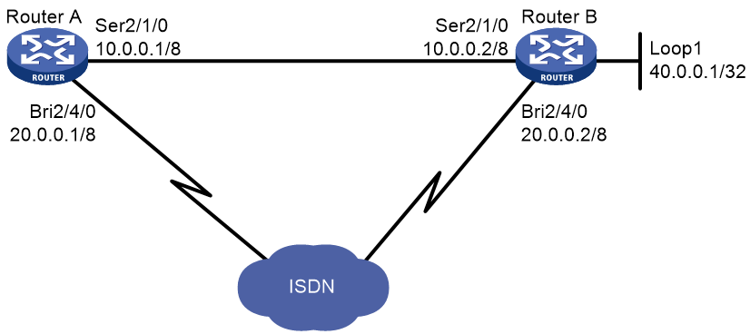
Procedure
1. Configure Router A:
# Create dialer group 1 and configure a dial rule for it.
<RouterA> system-view
[RouterA] dialer-group 1 rule ip permit
# Configure an IP address for BRI 2/4/0.
[RouterA] interface bri 2/4/0
[RouterA-Bri2/4/0] ip address 20.0.0.1 8
# Enable traditional DDR on BRI 2/4/0.
[RouterA-Bri2/4/0] dialer circular enable
# Associate BRI 2/4/0 with dialer group 1.
[RouterA-Bri2/4/0] dialer-group 1
# On BRI 2/4/0, configure the dial string for calling 40.0.0.1.
[RouterA-Bri2/4/0] dialer route ip 40.0.0.1 dial-number 8810052
[RouterA-Bri2/4/0] quit
# Configure an IP address for Serial 2/1/0.
[RouterA] interface serial 2/1/0
[RouterA-Serial2/1/0] ip address 10.0.0.1 8
# Enable PPP encapsulation on Serial 2/1/0.
[RouterA-Serial2/1/0] link-protocol ppp
[RouterA-Serial2/1/0] quit
# Configure OSPF.
[RouterA] ospf
[RouterA-ospf-1] area 0
[RouterA-ospf-1-area-0.0.0.0] network 10.0.0.0 0.255.255.255
[RouterA-ospf-1-area-0.0.0.0] network 20.0.0.0 0.255.255.255
[RouterA-ospf-1-area-0.0.0.0] quit
[RouterB-ospf-1] import-route direct
[RouterA-ospf-1] quit
# Create a dynamic route backup group.
[RouterA] standby routing-group 1 rule ip 30.0.0.1 32
# Configure the routes used by the serial interface to adopt higher priorities over those used by the dialup interface.
[RouterA] interface bri 2/4/0
[RouterA-Bri2/4/0] ospf cost 2000
[RouterA-Bri2/4/0] ospf network-type broadcast
# Enable dynamic route backup on BRI 2/4/0.
[RouterA-Bri2/4/0] standby routing-group 1
2. Configure Router B:
# Create dialer group 1 and configure a dial rule for it.
<RouterB> system-view
[RouterB] dialer-group 1 rule ip permit
# Configure an IP address for BRI 2/4/0.
[RouterB] interface bri 2/4/0
[RouterB-Bri2/4/0] ip address 20.0.0.2 8
# Enable traditional DDR on BRI 2/4/0.
[RouterB-Bri2/4/0] dialer circular enable
# Associate BRI 2/4/0 with dialer group 1.
[RouterB-Bri2/4/0] dialer-group 1
[RouterB-Bri2/4/0] quit
# Configure an IP address for Serial 2/1/0.
[RouterB] interface serial 2/1/0
[RouterB-Serial2/1/0] ip address 10.0.0.2 8
# Enable PPP encapsulation on Serial 2/1/0.
[RouterB-Serial2/1/0] link-protocol ppp
[RouterB-Serial2/1/0] quit
# Configure an IP address for Loopback 1.
[RouterB] interface loopback 1
[RouterB-Loopback1] ip address 40.0.0.1 32
[RouterB-Loopback1] quit
# Configure OSPF.
[RouterB] ospf
[RouterB-ospf-1] area 0
[RouterB-ospf-1-area-0.0.0.0] network 10.0.0.0 0.255.255.255
[RouterB-ospf-1-area-0.0.0.0] network 20.0.0.0 0.255.255.255
[RouterB-ospf-1-area-0.0.0.0] network 40.0.0.0 0.0.0.0
[RouterB-ospf-1-area-0.0.0.0] quit
[RouterB-ospf-1] import-route direct
Example: Configuring dynamic route backup for bundle DDR
Network configuration
As shown in Figure 15, Router A and Router B are directly connected through their serial interfaces. They are also connected to the ISDN through their ISDN BRI interfaces. The telephone number of Router B is 8810010. The telephone number of Router B is 8810052.
Enable dynamic route backup on Router A to monitor network segment 30.0.0.0/8 connected to Router B.
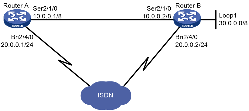
Procedure
1. Configure Router A:
# Create dialer group 1 and configure a dial rule for it.
<RouterA> system-view
[RouterA] dialer-group 1 rule ip permit
# Create local user userb for Router B, and configure the service type as PPP.
[RouterA] local-user userb class network
[RouterA-luser-network-userb] password simple userb
[RouterA-luser-network-userb] service-type ppp
[RouterA-luser-network-userb] quit
# Create a dynamic route backup group on Dialer 0.
[RouterA] interface dialer 0
[RouterA] standby routing-group 1 rule ip 30.0.0.1 32
# Configure an IP address for Dialer 0.
[RouterA-Dialer0] ip address 20.0.0.1 24
# Enable PPP encapsulation on Dialer 0.
[RouterA-Dialer0] link-protocol ppp
# Configure CHAP authentication on Dialer 0.
[RouterA-Dialer0] ppp authentication-mode pap
[RouterA-Dialer0] ppp pap local-user usera password simple usera
# Enable dynamic route backup on Dialer 0.
[RouterA-Dialer0] standby routing-group 1
# Enable bundle DDR on Dialer 0.
[RouterA-Dialer0] dialer bundle enable
# On Dialer 0, specify the host name of the remote router allowed to call in.
[RouterA-Dialer0] dialer peer-name userb
# Associate Dialer 0 with dialer group 1.
[RouterA-Dialer0] dialer-group 1
# On Dialer 0, configure the dial string for calling Router B.
[RouterA-Dialer0] dialer number 8810052
[RouterA-Dialer0] quit
# Assign BRI 2/4/0 to Dialer 0.
[RouterA] interface bri 2/4/0
[RouterA-Bri2/4/0] dialer bundle-member 0
# Configure PAP authentication on BRI 2/4/0.
[RouterA-Bri2/4/0] ppp authentication-mode pap
[RouterA-Bri2/4/0] ppp pap local-user usera password simple usera
[RouterA-Bri2/4/0] quit
# Configure an IP address for Serial 2/1/0.
[RouterA] interface serial 2/1/0
[RouterA-Serial2/1/0] ip address 10.0.0.1 8
# Enable PPP encapsulation on Serial 2/1/0.
[RouterA-Serial2/1/0] link-protocol ppp
[RouterA-Serial2/1/0] quit
# Configure RIP.
[RouterA] rip
[RouterA-rip-1] network 10.0.0.0
[RouterA-rip-1] network 20.0.0.0
[RouterA-rip-1] import-route direct
[RouterA-rip-1] quit
# Configure the routes used by the serial interface to adopt higher priorities than those used by the dialup interface.
[RouterA] interface bri 2/4/0
[RouterA-Bri2/4/0] rip metricin 2
2. Configure Router B:
# Create dialer group 1 and configure a dial rule for it.
<RouterB> system-view
[RouterB] dialer-group 1 rule ip permit
# Create local user usera for Router A, and configure the service type as PPP.
[RouterB] local-user usera class network
[RouterB-luser-network-usera] password simple usera
[RouterB-luser-network-usera] service-type ppp
[RouterB-luser-network-usera] quit
# Configure an IP address for Dialer 0.
[RouterB] interface dialer 0
[RouterB-Dialer0] ip address 20.0.0.2 24
# Enable PPP encapsulation on Dialer 0.
[RouterB-Dialer0] link-protocol ppp
# Configure PAP authentication on Dialer 0.
[RouterB-Dialer0] ppp authentication-mode pap
[RouterB-Dialer0] ppp pap local-user userb password simple userb
# Enable bundle DDR on Dialer 0.
[RouterB-Dialer0] dialer bundle enable
# On Dialer 0, specify the host name of the remote router allowed to call in.
[RouterB-Dialer0] dialer peer-name usera
# Associate Dialer 0 with dialer group 1.
[RouterB-Dialer0] dialer-group 1
# On Dialer 0, configure the dial string for calling Router A.
[RouterB-Dialer0] dialer number 8810010
[RouterB-Dialer0] quit
# Assign BRI 2/4/0 to Dialer 0.
[RouterB] interface bri 2/4/0
[RouterB-Bri2/4/0] dialer bundle-member 0
# Configure PAP authentication on BRI 2/4/0.
[RouterB-Bri2/4/0] ppp authentication-mode pap
[RouterB-Bri2/4/0] ppp pap local-user userb password simple userb
[RouterB-Bri2/4/0] quit
# Configure an IP address for Serial 2/1/0.
[RouterB] interface serial 2/1/0
[RouterB-Serial2/1/0] ip address 10.0.0.2 8
# Enable PPP encapsulation on Serial 2/1/0.
[RouterB-Serial2/1/0] link-protocol ppp
[RouterB-Serial2/1/0] quit
# Configure an IP address for Loopback 1.
[RouterB] interface loopback 1
[RouterB-Loopback1] ip address 30.0.0.1 32
[RouterB-Loopback1] quit
# Configure RIP.
[RouterB] rip
[RouterB-rip-1] network 10.0.0.0
[RouterB-rip-1] network 20.0.0.0
[RouterB-rip-1] network 30.0.0.0
[RouterB-rip-1] import-route direct
Example: Configuring dynamic route backup for multiple networks
Network configuration
As shown in Figure 16, Router A and Router B are directly connected through serial interfaces running PPP. They are also connected through an ISDN switched network, enabling them to call each other by using traditional DDR. The telephone number of Router A is 660330, and that of Router B is 660220.
Configure dynamic route backup on Router A to monitor the networks 10.0.0.1/8, 11.0.0.1/8, and 12.0.0.1/8, which are all connected to Router B.
The PPP link acts as the primary link between Router A and Router B. When the routes to all the three networks become invalid, Router A automatically initiates a secondary link through ISDN to Router B.
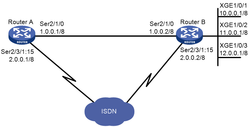
This network diagram only illustrates a simple application where a dynamic route backup group is used to monitor multiple subnets. In actual use, the monitored networks can be connected to multiple devices.
Procedure
1. Configure Router A:
# Create dialer group 1 and configure a dial rule for it.
<RouterA> system-view
[RouterA] dialer-group 1 rule ip permit
# Create a dynamic route backup group to monitor three networks.
[RouterA] standby routing-group 1 rule ip 10.0.0.0 255.0.0.0
[RouterA] standby routing-group 1 rule 11.0.0.0 255.0.0.0
[RouterA] standby routing-group 1 rule ip 12.0.0.0 255.0.0.0
# Bundle timeslots on E1 2/3/1 into a PRI group.
[RouterA] controller e1 2/3/1
[RouterA-E1 2/3/1] pri-set
[RouterA-E1 2/3/1] quit
# Configure an IP address for Serial 2/1/0.
[RouterA] interface serial 2/1/0
[RouterA-Serial2/1/0] ip address 1.0.0.1 255.0.0.0
# Enable PPP encapsulation on Serial 2/1/0.
[RouterA-Serial2/1/0] link-protocol ppp
[RouterA-Serial2/1/0] quit
# Configure an IP address for Serial 2/3/1:15.
[RouterA] interface serial 2/3/1:15
[RouterA-Serial2/3/1:15] ip address 2.0.0.1 255.0.0.0
# Enable traditional DDR on Serial 2/3/1:15.
[RouterA-Serial2/3/1:15] dialer circular enable
# Associate Serial 2/3/1:15 with dialer group 1.
[RouterA-Serial2/3/1:15] dialer-group 1
# On Serial 2/3/1:15, configure the dial string for calling the network 10.0.0.1/8.
[RouterA-Serial2/3/1:15] dialer route ip 10.0.0.0 mask 8 dial-number 660220
# Enable dynamic route backup on Serial 2/3/1:15.
[RouterA-Serial2/3/1:15] standby routing-group 1
[RouterA-Serial2/3/1:15] quit
# Configure RIP.
[RouterA] rip
[RouterA-rip-1] network 1.0.0.0
[RouterA-rip-1] network 2.0.0.0
[RouterA-rip-1] import-route direct
# Configure the routes used by the serial interface to adopt higher priorities than those used by the dialup interface.
[RouterA] interface serial 2/3/1:15
[RouterA-Serial2/3/1:15] rip metricin 2
2. Configure Router B:
# Create dialer group 1 and configure a dial rule for it.
[RouterB] system
[RouterB] dialer-group 1 rule ip permit
# Bundle timeslots on CE1 interface E1 2/3/1 into a PRI group.
[RouterB] controller e1 2/3/1
[RouterB-E1 2/3/1] pri-set
[RouterB-E1 2/3/1] quit
# Configure an IP address for Serial 2/1/0.
[RouterB] interface serial 2/1/0
[RouterB-Serial2/1/0] ip address 1.0.0.2 255.0.0.0
# Enable PPP encapsulation on Serial 2/1/0.
[RouterB-Serial2/1/0] link-protocol ppp
[RouterB-Serial2/1/0] quit
# Configure an IP address for Serial 2/3/1:15.
[RouterB] interface serial 2/3/1:15
[RouterB-Serial2/3/1:15] ip address 2.0.0.2 255.0.0.0
# Enable traditional DDR on Serial 2/3/1:15.
[RouterB-Serial2/3/1:15] dialer circular enable
# Associate Serial 2/3/1:15 with dialer group 1.
[RouterB-Serial2/3/1:15] dialer-group 1
# Configure the dial string for calling Serial 2/3/1:15 on Router A.
[RouterB-Serial2/3/1:15] dialer route ip 2.0.0.1 mask 8 dial-number 660330
[RouterB-Serial2/3/1:15] quit
# Configure the Ethernet interfaces connecting to the networks.
[RouterB] interface gigabitethernet 1/0/1
[RouterB-GigabitEthernet1/0/1] ip address 10.0.0.1 255.0.0.0
[RouterB-GigabitEthernet1/0/1] quit
[RouterB] interface gigabitethernet 1/0/2
[RouterB-GigabitEthernet1/0/2] ip address 11.0.0.1 255.0.0.0
[RouterB-GigabitEthernet1/0/2] quit
[RouterB] interface ethernet 1/0/3
[RouterB-GigabitEthernet1/0/3] ip address 12.0.0.1 255.0.0.0
[RouterB-GigabitEthernet1/0/3] quit
# Configure RIP.
[RouterB] rip
[RouterB-rip-1] network 1.0.0.0
[RouterB-rip-1] network 2.0.0.0
[RouterB-rip-1] network 10.0.0.0
[RouterB-rip-1] network 11.0.0.0
[RouterB-rip-1] network 12.0.0.0
[RouterB-rip-1] import-route direct
Troubleshooting
Failure to establish a dialup connection
Symptom
DDR dialup connection cannot be established because the modem does not dial when the router forwards data.
Solution
To resolve the problem:
1. Verify that the modem and phone cable connections are correct, and that the modem initialization process is correct.
2. Verify that the dialup interface, if it is synchronous/asynchronous, is configured as an asynchronous interface in protocol mode.
3. Verify that DDR is enabled on the dialup interface.
4. Verify that a dialer route or dialer number command is available for the packets.
Ping failure
Symptom
The remote end cannot be pinged after the modem is connected.
Solution
To resolve the problem:
1. Use the debugging ppp all command to verify that the two ends use the same link layer encapsulation and have correct PPP parameters configured for authentication.
2. Verify that a correct IP address is assigned to the dialup interface.
3. Verify that DDR is enabled on the dialup interface.
4. Verify that the correct dialer-group and dialer-group rule commands are configured and associated to ensure that the packets can pass.
5. Use the debugging dialer event and debugging dialer packet commands to locate the problem.