- Table of Contents
- Related Documents
-
| Title | Size | Download |
|---|---|---|
| 05-ATM configuration | 307.05 KB |
ATM connections and ATM switching
Restrictions: Hardware compatibility with ATM
Configuring the ATM AAL5 encapsulation type
Configuring the ATM service type
Configuring applications carried by ATM
Re-marking the CLP flag value of ATM cells
Display and maintenance commands for ATM
Example: Configuring ATM PVC transmission priority
Link state error in IPoA application
Link report error in PPPoA application
PVC state is down when ATM interface state is up
Ping failure after PPPoA configuration
Configuring ATM
About ATM
Asynchronous Transfer Mode (ATM) is a technology based on packet transmission mode, and it also incorporates the high speed of circuit transmission mode. Due to its flexibility and support for multimedia services, ATM is regarded as a core broadband technology.
ATM cells
As defined by the ITU-T, data is encapsulated in cells in ATM. Each ATM cell is 53 bytes in length, of which the first 5 bytes contain cell header information and the last 48 bytes contain payload. The major function of the cell header is to identify virtual connection. In addition, it can be used to carry limited flow control, congestion control, and error control information.
ATM connections and ATM switching
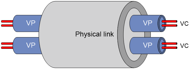
ATM is connection-oriented, and ATM connections are logical (virtual) connections. In an ATM network, you can create logical connections called virtual paths (VPs) and virtual circuits (VCs) on physical links.
As shown in Figure 1, you can create multiple VPs on a physical link, and each VP can be demultiplexed into multiple VCs. Cells from different users are transmitted over different VPs and VCs, which are identified by virtual path identifier (VPI) and virtual channel identifier (VCI). ATM uses VPI/VCI pairs to identify virtual connections.
Figure 1 Physical link, VP, and VC
ATM interfaces support only manually created permanent virtual circuits (PVCs), not switched virtual circuits (SVCs) created through the exchange of signals. A PVC is identified by a VPI/VCI pair.
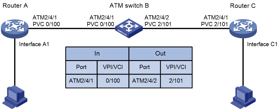
In an ATM network, an ATM switch forwards ATM cells by looking up the switching entries and changing the VPIs/VCIs. In PVC mode, the network administrator configures the switching entries and assigns VPIs/VCIs. Users can use the assigned VPIs/VCIs to configure the PVCs. If the ATM interfaces of two ATM devices are directly connected, they must be configured with the same VPIs/VCIs.
Figure 2 shows a typical ATM switching process:
1. Router A forwards a cell through PVC 0/100 on interface ATM 2/4/1.
2. ATM switch B receives the cell through PVC 0/100 on interface ATM 2/4/1.
3. ATM switch B looks up its switching entries and forwards the cell through PVC 2/101 on interface ATM 2/4/2.
4. Router C receives the cell through PVC 2/101 on interface ATM 2/4/1.
ATM architecture
ATM has a three-dimensional architecture. It contains the user plane, control plane, and management plane.
Both the user plane and the control plane are divided into the following layers: physical layer, ATM layer, ATM Adaptation Layer (AAL), and upper layer. Each layer is further divided into sublayers.
The control plane establishes and tears down connections with signaling protocols. The management plane contains layer management and plane management. Layer management manages the layers in each plane and has a layered structure corresponding to other planes. Plane management manages the system and the communications between different planes.
Figure 3 shows the relationships between layers and planes in ATM.

ATM layers have the following functions:
· Physical layer—Provides transmission channels for ATM cells. At this layer, cells received from the ATM layer are transferred into a continuous bit stream after transmission overheads are added to them. Meanwhile, continuous bit streams received from physical media are restored to cells, which are then passed to the ATM layer.
· ATM layer—Resides over the physical layer, and implements cell-based communication with its peer layer by invoking the services provided by the physical layer. It is independent of physical media, implementation of the physical layer, and types of services being carried. AAL passes 48-byte payloads, which are called segmentation and reassembly protocol data units (SAR-PDUs) to the ATM layer. The ATM layer encapsulates the 48-byte payloads in 5-byte headers, and passes 53-byte cells to the physical layer. Other functions of the ATM layer include VPI/VCI transmission, cell multiplexing/demultiplexing, and generic flow control.
· ATM Adaptation Layer—Provides interfaces between high-level protocols and the ATM Layer. It forwards information between the ATM layer and upper-layer protocols. Four types of AAL are available: AAL1, AAL2, AAL3/4, and AAL5, each of which supports specific services provided in an ATM network. H3C uses AAL5 for data communication services.
· ATM upper-layer protocols—Responsible for WAN interconnection, Layer 3 interconnection, and multiprotocol over ATM (such as IP, IPoE, PPP, and PPPoE).
ATM service types
ATM supports the following service types:
· Constant Bit Rate (CBR).
· Unspecified Bit Rate (UBR).
· Variable Bit Rate-Real Time (VBR-RT).
· Variable Bit Rate-Non Real Time (VBR-NRT).
They are used for the QoS purpose.
CBR
CBR provides ensured, constant bandwidth. The bandwidth assigned to the CBR service is decided by the Peak Cell Rate (PCR). With CBR service, a source station can send ATM cells at PCR constantly with assured QoS.
Typically, CBR is suitable for jitter-sensitive, real-time applications, such as audio and video.
VBR-RT
The VBR-RT service is provided for applications that have strict restrictions on delay and jitter, such as audio and video.
A VBR-RT connection is described by the PCR, sustainable cell rate (SCR), and maximum burst size (MBS). With the VBR-RT service, a station can send burst traffic at PCR with the maximum traffic size being MBS without cell loss and the average cell rate being SCR.
VBR-NRT
The VBR-NRT service supports non-real-time applications with burst traffic. A VBR-NRT connection is described by PCR, SCR, and MBS. The VBR-NRT service is suitable for applications sensitive to cell loss but not to delay.
UBR
The UBR service does not make any service quality commitment, guaranteeing neither cell loss ratio (CLR) nor cell delay. When traffic congestion occurs, cells of the UBR service are dropped first. The UBR service is suitable for applications with low requirements for delay and bandwidth.
ATM applications
IPoA
IP over ATM (IPoA) enables ATM to carry IP packets. In an IPoA implementation, ATM acts as the data link layer protocol for the IP hosts on the same network. To enable these hosts to communicate across an ATM network, IP packets must be encapsulated in ATM cells.
By making full use of the advantages of ATM, IPoA delivers excellent network performance and mature QoS assurance.
IPoEoA
IP over Ethernet over ATM (IPoEoA) uses a three-layer architecture, with IP encapsulation at the top layer, IP over Ethernet (IPoE) in the middle, and IPoEoA at the bottom.
IPoEoA is suitable where Ethernet packets are to be forwarded through ATM interfaces.
PPPoA
PPP over ATM (PPPoA) enables ATM to carry PPP protocol packets. With PPPoA, PPP packets, in which IP packets or other protocols' packets are encapsulated, are encapsulated in ATM cells. In this implementation, ATM is the carrier of PPP packets and the communication process of PPPoA is managed by PPP, which allows for flexibility and rich applications.
PPPoEoA
PPPoE over ATM (PPPoEoA) enables ATM to carry PPPoE protocol packets. With PPPoEoA, Ethernet packets are encapsulated in ATM cells, through which you can use a PVC to implement the functionality of Ethernet. PPPoE uses the Client/Server model. It encapsulates PPP packets in Ethernet frames and provides point-to-point connectivity over Ethernet.
ATM OAM
OAM has the following expansions:
· Operation and Maintenance in the ITU-T I.610 recommendation (02/99).
· Operation Administration and Maintenance in LUCENT APC User Manual (03/99).
Whichever expansion is used, OAM provides a way of detecting faults, isolating faults, and monitoring network performance without interrupting ongoing services. By inserting OAM cells, which are constructed in the standard ATM cell format, in cell streams, you can obtain specific information about the network.
ATM OAM provides the following functions:
· OAM Alarm Indication Signal/Remote Defect Indication—The PVC goes down when specific number of successive AIS/RDI alarm cells are received. The PVC comes up when no AIS/RDI alarm cells are received within the specified time.
· OAM F5 Loopback—Sends OAM F5 Loopback cells at the specified interval after you enable OAM F5 Loopback transmission and retransmission detection and specify related parameters. If the sender fails to receive a response cell within the specified interval, it sends an OAM F5 Loopback cell again. The state of the PVC is updated during the Loopback detection. The PVC comes up when the specified number of successive OAM F5 Loopback cells are received. The PVC goes down when the specified number of successive OAM F5 Loopback cells are not received.
· OAM F5 end-to-end—Sends OAM F5 end-to-end cells through the specified PVC on the specified ATM interface. If no response is received within the specified period, the link might be disconnected or congested.
Restrictions: Hardware compatibility with ATM
ATM is supported only when the router is installed with the ATM-OC3, ADSL2+, G.shdsl, or G.shdsl.Bis interface module.
ATM tasks at a glance
To configure ATM, perform the following tasks:
1. Configuring an ATM interface
For information about ATM interface configuration, see Interface Configuration Guide.
2. Configuring a PVC or PVC group
3. Configuring the ATM AAL5 encapsulation type
4. Configuring the ATM service type
5. Configuring applications carried by ATM
6. (Optional.) Configuring VP policing
7. (Optional.) Re-marking the CLP flag value of ATM cells
8. (Optional.) Configuring ATM OAM functions
Configuring a PVC
Restrictions and guidelines
In PVC mode, the network administrator configures the switching entries and assigns VPI/VCI values. You can configure the PVCs by using the assigned VPI/VCI values. If the ATM interfaces of two ATM devices are directly connected, you must configure the same VPI/VCI values for the interfaces.
Procedure
1. Enter system view.
system-view
2. Enter ATM interface view or ATM subinterface view.
interface atm { interface-number | interface-number.subnumber }
3. Create a PVC and enter PVC view.
pvc { pvc-name [ vpi/vci ] | vpi/vci }
4. Bring up the PVC.
undo shutdown
By default, the PVC is up.
Configuring a PVC group
About this task
A PVC group can share traffic load among PVCs in it by transmitting IP packets of different priorities through different PVCs.
You can configure the priority of IP packets carried by each PVC. IP packets are transmitted through the PVC corresponding to the priority of the IP packets.
· If no corresponding PVC is found, the IP packets are transmitted through the default PVC.
· If no default PVC is configured, the IP packets are distributed across the PVCs that are not configured with priorities on a per-packet basis.
· If all PVCs are configured with priorities, the IP packets are dropped.
Data packets that are not IP packets are distributed across all PVCs in the PVC group on a per-packet basis.
All PVCs in a PVC group obtain the encapsulation type and protocol type from the PVC group.
Procedure
1. Enter system view.
system-view
2. Enter ATM interface view or ATM subinterface view.
interface atm { interface-number | interface-number.subnumber }
3. Create a PVC group and enter PVC group view.
pvc-group group-number
4. Create a PVC and enter PVC view.
pvc { pvc-name [ vpi/vci ] | vpi/vci }
5. Configure priority of IP packets carried by the PVC.
precedence { min-number [ to max-number ] | default }
By default, no priority is configured.
6. Bring up the PVC.
undo shutdown
By default, the PVC is up.
Configuring the ATM AAL5 encapsulation type
About this task
ATM AAL5 encapsulation includes the following types:
· aal5snap—Logical Link Control (LLC)/Subnet Access Protocol (SNAP) encapsulation.
· aal5mux—MUX multiplexing encapsulation.
· aal5nlpid—RFC 1490 encapsulation.
Different encapsulations use different formats and support different mappings.
Table 1 shows the support of encapsulation types for ATM applications.
Table 1 Encapsulation type support for ATM applications
|
ATM application |
aal5snap |
aal5mux |
aal5nlpid |
|
IPoA |
Supported |
Supported (InARPoA not supported) |
Supported (InARPoA not supported) |
|
IPoEoA |
Supported |
Supported |
Not supported |
|
PPPoA |
Supported |
Supported |
Not supported |
|
PPPoEoA |
Supported |
Supported |
Not supported |
|
|
NOTE: When aal5snap is used, a PVC or PVC group can carry two or more protocols at the same time. When aal5mux is used, a PVC or PVC group carries only one protocol at a time. |
Restrictions and guidelines
Devices on the two ends must be configured with the same ATM AAL5 encapsulation types.
Only aal5snap supports InARP. You cannot configure InARP when aal5mux or aal5nlpid is used.
When you change the encapsulation type for a PVC or PVC group, and the mappings that you have configured conflict with the new encapsulation type, the PVC or PVC group deletes the configurations of all conflicting mappings.
Procedure
1. Enter system view.
system-view
2. Enter ATM interface view or ATM subinterface view.
interface atm { interface-number | interface-number.subnumber }
3. Enter PVC view or PVC group view.
¡ Enter PVC view.
pvc { pvc-name [ vpi/vci ] | vpi/vci }
¡ Enter PVC group view.
pvc-group group-number
4. Configure the ATM AAL5 encapsulation type.
encapsulation { aal5mux | aal5nlpid | aal5snap }
The default encapsulation type is aal5snap.
Configuring the ATM service type
About this task
ATM supports the following service types: CBR, UBR, VBR-RT, and VBR-NRT. You can configure service types for PVCs, and configure different transmission priorities for PVCs associated with the UBR, VBR-NRT, and VBR-RT services. A greater value represents a higher priority. PVCs with higher priorities occupy more bandwidths. PVCs with the same priority occupy the same bandwidths. You cannot configure transmission priorities for CBR services.
Procedure
1. Enter system view.
system-view
2. Enter ATM interface view or ATM subinterface view.
interface atm { interface-number | interface-number.subnumber }
3. Enter PVC view or PVC view in PVC group.
¡ Enter PVC view.
pvc { pvc-name [ vpi/vci ] | vpi/vci }
¡ Execute the following commands in sequence to enter PVC view in a PVC group.
pvc-group group-number
pvc { pvc-name [ vpi/vci ] | vpi/vci }
4. Configure the service type and related parameters for the PVC.
¡ Set the service type to CBR and configure related parameters.
service cbr output-pcr [ cdvt cdvt-value ]
¡ Set the service type to UBR and configure related parameters.
service ubr output-pcr
¡ Set the service type to VBR-NRT and configure related parameters.
service vbr-nrt output-pcr output-scr output-mbs
¡ Set the service type to VBR-RT and configure related parameters.
service vbr-rt output-pcr output-scr output-mbs
The default service type is UBR.
The newly configured service type overwrites the existing ones. You can configure different service types for different PVCs of a PVC group or interface.
5. Configure the transmission priority for the PVC.
transmit-priority priority
By default, the transmission priority is:
¡ 0 for UBR services.
¡ 5 for VBR-NRT services.
¡ 8 for VBR-RT services.
When you change the service type for the PVC, the transmission priority of the PVC is restored to the default.
Configuring applications carried by ATM
Configuring IPoA
About this task
To enable the upper-layer protocols to find a remote device by its IP address, map the IP address of the remote device to the local PVC or PVC group.
To configure an IP mapping, use one of the following methods:
· Static IP address mapping—Maps the IP address of the remote interface to the PVC or PVC group.
· Default mapping—If a packet cannot find the mapping for the next hop address, the packet is transmitted through the PVC or PVC group configured with the default mapping.
· InARP mapping—Uses Inverse Address Resolution Protocol (InARP) to resolve the IP address of the remote interface that is connected to the local PVC or PVC group. You do not need to configure a static IP address for the PVC or PVC group. Figure 4 shows the InARP working process. The IP addresses are the IP addresses of the ATM interfaces to which the PVC or PVC group belongs.
Figure 4 InARP working process

Restrictions and guidelines
All encapsulation types support IPoA mapping, but only aal5snap supports InARP mapping. You cannot configure InARP mapping when aal5mux or aal5nlpid is used.
Multiple IP addresses can be mapped to the same PVC or PVC group. You can configure static IP mapping, default mapping, and InARP mapping at the same time. Different PVCs or PVC groups on the same interface cannot be mapped to the same IP address. The PVCs or PVC groups on the same interface can be configured with only one default mapping.
If the interfaces of two routers are connected back-to-back, the local PVC mapped to the remote IP address must have the same VPI/VCI value as the remote PVC mapped to the local IP address.
Procedure
1. Enter system view.
system-view
2. Enter ATM interface view or ATM subinterface view.
interface atm { interface-number | interface-number.subnumber }
3. Enter PVC view or PVC group view.
¡ Enter PVC view.
pvc { pvc-name [ vpi/vci ] | vpi/vci }
¡ Enter PVC group view.
pvc-group group-number
4. Configure an IPoA mapping to enable the PVC or PVC group to carry IP packets.
map ip { ip-address | default | inarp [ minutes ] }
5. Enable the broadcast attribute for the PVC or PVC group.
broadcast
By default, the broadcast attribute is disabled.
On an ATM interface, multicast or broadcast packets are sent through all PVCs or PVC groups that have the broadcast attribute enabled.
You must configure this command on a PVC or PVC group where broadcast or multicast packets must be sent.
Configuring IPoEoA
About this task
For IPoEoA applications, you can associate multiple PVCs with one Layer 3 virtual Ethernet (VE) interface. The PVCs associated with the same VEth interface are interconnected at Layer 2.
PPPoEoA uses VEth interfaces to carry Ethernet frames over ATM. A VEth interface has Ethernet characteristics and can be dynamically created. The following is the protocol stack used by a VEth interface:
· ATM PVC (the bottom layer).
· Ethernet (the link layer).
· Network layer and other upper layers (the same as those for common Ethernet interfaces).
Restrictions and guidelines for IPoEoA configuration
Before you configure IPoEoA and PPPoEoA, you must create a VEth interface.
Configuring a VEth interface-to-PVC mapping
1. Enter system view.
system-view
2. Create a VEth interface or VEth subinterface and enter its view.
interface virtual-ethernet { interface-number | interface-number.subnumber }
3. Configure an IP address for the VEth interface.
ip address ip-address { mask | mask-length }
For an IPoEoA application, configure the IP address for VEth interfaces instead of ATM interfaces. The IP address configuration does not take effect on ATM interfaces.
4. Return to system view.
quit
5. Enter ATM interface view or ATM subinterface view.
interface atm { interface-number | interface-number.subnumber }
6. Enter PVC view or PVC group view.
¡ Enter PVC view.
pvc { pvc-name [ vpi/vci ] | vpi/vci }
¡ Enter PVC group view.
pvc-group group-number
7. Configure an IPoEoA mapping.
map bridge virtual-ethernet interface-number
By default, no mappings exist.
This command references the VEth interface previously created.
Configuring the VEth interface
1. Enter system view.
system-view
2. Enter VEth interface view.
interface virtual-ethernet interface-number
The device supports a maximum of 1024 VEth interfaces.
3. (Optional.) Configure the description of the interface.
description text
The default interface description is interface name Interface. For example, Virtual-Ethernet 0 Interface.
4. (Optional.) Configure the MTU for the interface.
mtu size
By default, the MTU for the interface is 1500 bytes.
5. (Optional.) Configure the MAC address for the interface.
mac-address mac-address
By default, the VEth interface uses the bridge MAC address as its MAC address.
6. (Optional.) Configure the expected bandwidth for the interface.
bandwidth bandwidth-value
By default, the expected bandwidth (in kbps) is the interface baud rate divided by 1000.
The expected bandwidth is an informational parameter used only by higher-layer protocols for calculation. You cannot adjust the actual bandwidth of an interface by using this command.
7. Bring up the interface.
undo shutdown
By default, the interface is up.
Configuring the VEth subinterface
1. Enter system view.
system-view
2. Enter VEth subinterface view.
interface virtual-ethernet interface-number.subnumber
3. (Optional.) Configure the description of the subinterface.
description text
The default interface description is interface name Interface.
4. (Optional.) Configure the MTU for the subinterface.
mtu size
By default, the MTU for the subinterface is 1500 bytes.
5. (Optional.) Configure the expected bandwidth for the subinterface.
bandwidth bandwidth-value
By default, the expected bandwidth (in kbps) is the subinterface baud rate divided by 1000.
The expected bandwidth is an informational parameter used only by higher-layer protocols for calculation. You cannot adjust the actual bandwidth of an interface by using this command.
6. Bring up the subinterface.
undo shutdown
By default, the subinterface is up.
Restoring the default settings for the VEth interface or VEth subinterface
|
|
CAUTION: Restoring the default interface settings might interrupt ongoing network services. Make sure you are fully aware of the impact of this operation when you perform it on a live network. |
To restore the default settings for the VEth interface or VEth subinterface:
1. Enter system view.
system-view
2. Enter VEth interface or VEth subinterface view.
interface virtual-ethernet { interface-number | interface-number.subnumber }
3. Restore the default settings for the VEth interface or VEth subinterface.
default
This command might fail to restore the default settings for some commands for reasons such as command dependencies and system restrictions. You can use the display this command in interface view to check for these commands, and use their undo forms or follow the command reference to restore their respective default settings. If your restoration attempt still fails, follow the error message instructions to resolve the problem.
Configuring PPPoA
Restrictions and guidelines
To transmit PPP packets across an ATM network, you must create a virtual-template (VT) interface.
When two routers are connected by using DSL interfaces through a dial-up connection, configure them as a PPPoA server and client. The PPPoA server acts as the PPP server, and you must configure an address pool for it to assign an IP address to the remote node. The PPPoA client acts as the PPP client, and you must configure address negotiation on it to accept the IP address assigned by the server end. For more information, see "Configuring PPP and MP."
When you configure a static route for the VT interface, specify the next hop instead of the output interface. If you have to specify an output interface, make sure the physical interface bound to the VT is valid to ensure correct packet transmission.
Procedure
1. Enter system view.
system-view
2. Create a VT interface and enter its view.
interface virtual-template vt-number
3. Configure PPP authentication and IP address.
¡ For the PPP server, configure an address pool to assign an IP address to the remote node.
¡ For the PPP client, configure address negotiation to accept the IP address assigned by the server end.
For more information, see "Configuring PPP" and "Configuring MP."
Configure PPP authentication and IP address on the VT interface instead of an ATM interface. The IP address configuration does not take effect on ATM interfaces.
4. Return to system view.
quit
5. Enter ATM interface view or ATM subinterface view.
interface atm { interface-number | interface-number.subnumber }
6. Enter PVC view or PVC group view.
¡ Enter PVC view.
pvc { pvc-name [ vpi/vci ] | vpi/vci }
¡ Enter PVC group view.
pvc-group group-number
7. Configure a PPPoA mapping.
map ppp virtual-template vt-number
Configuring PPPoEoA
About this task
For IPoEoA applications, you can associate multiple PVCs with one Layer 3 virtual Ethernet (VE) interface. The PVCs associated with the same VEth interface are interconnected at Layer 2.
PPPoEoA uses VEth interfaces to carry Ethernet frames over ATM. A VEth interface has Ethernet characteristics and can be dynamically created. The following is the protocol stack used by a VEth interface:
· ATM PVC (the bottom layer).
· Ethernet (the link layer).
· Network layer and other upper layers (the same as those for common Ethernet interfaces).
Restrictions and guidelines for PPPoEoA configuration
Before you configure IPoEoA and PPPoEoA, you must create a VEth interface.
When you configure a static route for the VT interface, specify the next hop instead of the output interface. If you have to specify an output interface, make sure the physical interface bound to the VT is valid to ensure correct packet transmission.
Configuring a VEth interface-to-PVC mapping
1. Enter system view.
system-view
2. Create a VT interface and enter its view.
interface virtual-template vt-number
3. Configure PPP authentication and IP address.
¡ For the PPP server, configure an address pool to assign an IP address to the remote node.
¡ For the PPP client, configure address negotiation to accept the IP address assigned by the server end.
For more information, see "Configuring PPP" and "Configuring MP."
Configure PPP authentication and IP address on the VT interface instead of an ATM interface. The IP address configuration does not take effect on ATM interfaces.
4. Return to system view.
quit
5. Create a VEth interface or VEth subinterface and enter its view.
interface virtual-ethernet { interface-number | interface-number.subnumber }
6. Configure PPPoE parameters on the VEth interface.
Bind the PPPoE server to a VT interface, and bind the PPPoE client to a Dialer interface for dial-in access. For more information, see "Configuring PPPoE."
7. Return to system view.
quit
8. Enter ATM interface view or ATM subinterface view.
interface atm { interface-number | interface-number.subnumber }
9. Enter PVC view or PVC group view.
¡ Enter PVC view.
pvc { pvc-name [ vpi/vci ] | vpi/vci }
¡ Enter PVC group view.
pvc-group group-number
10. Configure a PPPoEoA mapping.
map bridge virtual-ethernet { interface-number | interface-number.subnumber }
By default, no mappings exist.
This command references the VEth interface previously created.
Configuring the VEth interface
1. Enter system view.
system-view
2. Enter VEth interface view.
interface virtual-ethernet interface-number
The device supports a maximum of 1024 VEth interfaces.
3. (Optional.) Configure the description of the interface.
description text
The default interface description is interface name Interface. For example, Virtual-Ethernet 0 Interface.
4. (Optional.) Configure the MTU for the interface.
mtu size
By default, the MTU for the interface is 1500 bytes.
5. (Optional.) Configure the MAC address for the interface.
mac-address mac-address
By default, the VEth interface uses the bridge MAC address as its MAC address.
6. (Optional.) Configure the expected bandwidth for the interface.
bandwidth bandwidth-value
By default, the expected bandwidth (in kbps) is the interface baud rate divided by 1000.
The expected bandwidth is an informational parameter used only by higher-layer protocols for calculation. You cannot adjust the actual bandwidth of an interface by using this command.
7. Bring up the interface.
undo shutdown
By default, the interface is up.
Configuring the VEth subinterface
1. Enter system view.
system-view
2. Enter VEth subinterface view.
interface virtual-ethernet interface-number.subnumber
3. (Optional.) Configure the description of the subinterface.
description text
The default interface description is interface name Interface.
4. (Optional.) Configure the MTU for the subinterface.
mtu size
By default, the MTU for the subinterface is 1500 bytes.
5. (Optional.) Configure the expected bandwidth for the subinterface.
bandwidth bandwidth-value
By default, the expected bandwidth (in kbps) is the subinterface baud rate divided by 1000.
The expected bandwidth is an informational parameter used only by higher-layer protocols for calculation. You cannot adjust the actual bandwidth of an interface by using this command.
6. Bring up the subinterface.
undo shutdown
By default, the subinterface is up.
Restoring the default settings for the VEth interface or VEth subinterface
|
|
CAUTION: Restoring the default interface settings might interrupt ongoing network services. Make sure you are fully aware of the impact of this operation when you perform it on a live network. |
To restore the default settings for the VEth interface or VEth subinterface:
1. Enter system view.
system-view
2. Enter VEth interface or VEth subinterface view.
interface virtual-ethernet { interface-number | interface-number.subnumber }
3. Restore the default settings for the VEth interface or VEth subinterface.
default
This command might fail to restore the default settings for some commands for reasons such as command dependencies and system restrictions. You can use the display this command in interface view to check for these commands, and use their undo forms or follow the command reference to restore their respective default settings. If your restoration attempt still fails, follow the error message instructions to resolve the problem.
Configuring VP policing
About this task
A VP is the collection of all PVCs with the same VPI value. VP policing is used to manage the maximum bandwidth of the VP, and monitor the traffic of the inbound and outbound directions of the VP on a physical interface. When the maximum transmission rate of the VP exceeds the specified value, the exceeded flows are dropped. When VP policing is applied, the parameters of PVC are still valid. Packets can be transmitted or received only when the parameters of PVC and VP policing are met. In calculating the traffic, the LLC/SNAP, MUX, and NLPID headers are included, but the ATM cell header is not included.
Procedure
1. Enter system view.
system-view
2. Enter ATM interface view.
interface atm interface-number
3. Configure parameters for VP policing.
vp limit vpi scr
By default, VP policing is disabled.
Re-marking the CLP flag value of ATM cells
About this task
You can re-mark the cell loss priority (CLP) flag value of ATM cells to specify the drop precedence for the cells.
Procedure
1. Enter system view.
system-view
2. Configure a traffic class.
a. Create a traffic class and enter its view.
traffic classifier classifier-name [ operator { and | or } ]
b. Configure match criteria.
if-match [ not ] match-criteria
By default, no match criteria exist.
c. Return to system view.
quit
3. Configure a traffic behavior.
a. Create a traffic behavior and enter its view.
traffic behavior behavior-name
b. Re-mark the CLP flag value of ATM cells.
remark [ green | red | yellow ] atm-clp atm-clp-value
By default, the CLP flag value of ATM cells is not re-marked.
The CLP flag value of ATM cells is 0 or 1. The cells with a CLP flag value of 1 are dropped first when network congestion occurs.
c. Return to system view.
quit
4. Configure a QoS policy.
a. Create a QoS policy and enter its view.
qos policy policy-name
b. Associate a traffic class with a traffic behavior in the QoS policy.
classifier classifier-name behavior behavior-name [ insert-before before-classifier-name ]
By default, a traffic class is not associated with a traffic behavior.
c. Return to system view.
quit
5. Enter ATM interface view or ATM subinterface view.
interface atm { interface-number | interface-number.subnumber }
6. Enter PVC view or PVC view in PVC group.
¡ Enter PVC view.
pvc { pvc-name [ vpi/vci ] | vpi/vci }
¡ Execute the following commands in sequence to enter PVC view in a PVC group.
pvc-group group-number
pvc { pvc-name [ vpi/vci ] | vpi/vci }
7. Apply the QoS policy to the PVC.
qos apply policy policy-name outbound
By default, no QoS policy is applied to the PVC.
Configuring ATM OAM functions
Enabling ATM OAM functions
1. Enter system view.
system-view
2. Enter ATM interface view or ATM subinterface view.
interface atm { interface-number | interface-number.subnumber }
3. Enter PVC view or PVC view in PVC group.
¡ Enter PVC view.
pvc { pvc-name [ vpi/vci ] | vpi/vci }
¡ Execute the following commands in sequence to enter PVC view in a PVC group.
pvc-group group-number
pvc { pvc-name [ vpi/vci ] | vpi/vci }
4. Enable OAM F5 Loopback transmission and retransmission detection.
oam loopback interval [ up up-count down down-count retry retries ]
By default, OAM F5 Loopback cell transmission is disabled. Responses are sent if an OAM F5 Loopback cell is received.
5. (Optional.) Configure related parameters for AIS/RDI alarm cell detection.
oam ais-rdi up up-seconds down down-seconds
By default, the PVC goes down when the system receives successive AIS/RDI alarm cells in one second. The PVC comes up when the system does not receive any AIS/RDI alarm cells in 3 seconds.
Checking the link connection
Send OAM F5 end-to-end cells to check the link connection.
oam ping interface atm { interface-number | interface-number.subnumber } pvc { pvc-name | vpi/vci } [ number timeout ]
This command is available in any view.
Display and maintenance commands for ATM
Execute display commands in any view and reset commands in user view.
|
Task |
Command |
|
Display PVC information. |
display atm pvc-info [ interface interface-type { interface-number | interface-number.subnumber } [ pvc { pvc-name | vpi/vci } ] ] |
|
Display PVC group information. |
display atm pvc-group [ interface interface-type { interface-number | interface-number.subnumber } [ pvc-group group-number ] ] |
|
Display mapping information about PVCs or PVC groups. |
display atm map-info [ interface interface-type { interface-number | interface-number.subnumber } [ pvc { pvc-name | vpi/vci } | pvc-group group-number ] ] |
|
Display VEth interface information. |
display interface [ virtual-ethernet [ interface-number ] ] [ brief [ description | down ] ] |
|
Clear PVC statistics. |
reset atm interface [ interface-type { interface-number | interface-number.subnumber } ] |
|
Clear VEth interface statistics. |
reset counters interface [ virtual-ethernet [ interface-number | interface-number.subnumber ] ] |
ATM configuration examples
Example: Configuring IPoA
Network configuration
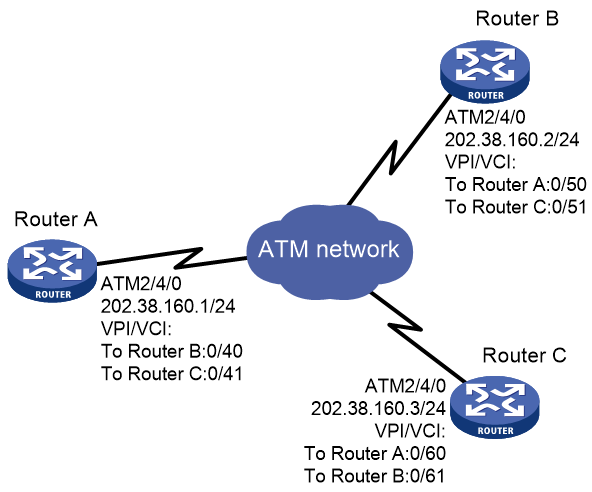
As shown in Figure 5, Router A, B, and C are connected to the ATM network for intercommunication.
The IP addresses of the ATM interfaces of the three routers are 202.38.160.1/24, 202.38.160.2/24, and 202.38.160.3/24.
In the ATM network:
· The VPIs/VCIs of Router A are 0/40 and 0/41, connected to Router B and Router C, respectively.
· The VPIs/VCs of Router B are 0/50 and 0/51, connected to Router A and Router C, respectively.
· The VPIs/VCIs of Router C are 0/60 and 0/61, connected to Router A and Router B, respectively.
All the PVCs on ATM interfaces of the three routers operate in IPoA application mode.
Procedure
1. Configure Router A:
# Enter the view of interface ATM 2/4/0 and configure an IP address for it.
<RouterA> system-view
[RouterA] interface atm 2/4/0
[RouterA-ATM2/4/0] ip address 202.38.160.1 255.255.255.0
# Create PVCs, and enable them to carry IP.
[RouterA-ATM2/4/0] pvc to_b 0/40
[RouterA-ATM2/4/0-pvc-to_b-0/40] map ip 202.38.160.2
[RouterA-ATM2/4/0-pvc-to_b-0/40] quit
[RouterA-ATM2/4/0] pvc to_c 0/41
[RouterA-ATM2/4/0-pvc-to_c-0/41] map ip 202.38.160.3
2. Configure Router B:
# Enter the view of interface ATM 2/4/0 and configure an IP address for it.
<RouterB> system-view
[RouterB] interface atm 2/4/0
[RouterB-ATM2/4/0] ip address 202.38.160.2 255.255.255.0
# Create PVCs, and enable them to carry IP.
[RouterB-ATM2/4/0] pvc to_a 0/50
[RouterB-ATM2/4/0-pvc-to_a-0/50] map ip 202.38.160.1
[RouterB-ATM2/4/0-pvc-to_a-0/50] quit
[RouterB-ATM2/4/0] pvc to_c 0/51
[RouterB-ATM2/4/0-pvc-to_c-0/51] map ip 202.38.160.3
3. Configure Router C:
# Enter the view of interface ATM 2/4/0 and configure an IP address for it.
<RouterC> system-view
[RouterC] interface atm 2/4/0
[RouterC-ATM2/4/0] ip address 202.38.160.3 255.255.255.0
# Create PVCs, and enable them to carry IP.
[RouterC-ATM2/4/0] pvc to_a 0/60
[RouterC-ATM2/4/0-pvc-to_a-0/60] map ip 202.38.160.1
[RouterC-ATM2/4/0-pvc-to_a-0/60] quit
[RouterC-ATM2/4/0] pvc to_b 0/61
[RouterC-ATM2/4/0-pvc-to_b-0/61] map ip 202.38.160.2
Verifying the configuration
# Use the ping command to verify that the three routers can ping each other successfully. (Details not shown.)
Example: Configuring IPoEoA
Network configuration
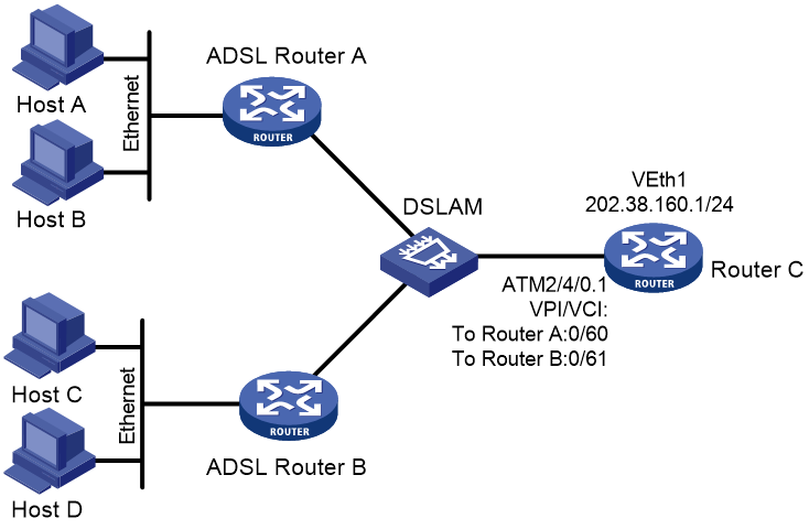
As shown in Figure 6, the hosts in the two Ethernets are connected to the ATM network through ADSL Router A and ADSL Router B. They communicate with Router C through DSLAM.
The IP address of the VEth interface of Router C is 202.38.160.1.
The VPI/VCI values of the two PVCs connecting Router C and DSLAM are 0/60 and 0/61, pointing to Router A and Router B, respectively.
Both the WAN port of Router C and the DSL interfaces of the ADSL routers use IPoEoA.
Procedure
1. Configure Router C:
# Create a VEth interface and configure an IP address for it.
<RouterC> system-view
[RouterC] interface virtual-ethernet 1
[RouterC-Virtual-Ethernet1] ip address 202.38.160.1 255.255.255.0
[RouterC-Virtual-Ethernet1] quit
# Create PVCs, and enable them to carry IPoE.
[RouterC] interface atm 2/4/0.1
[RouterC-ATM2/4/0.1] pvc to_adsl_a 0/60
[RouterC-ATM2/4/0.1-pvc-to_adsl_a-0/60] map bridge virtual-ethernet 1
[RouterC-ATM2/4/0.1-pvc-to_adsl_a-0/60] quit
[RouterC-ATM2/4/0.1] pvc to_adsl_b 0/61
[RouterC-ATM2/4/0.1-pvc-to_adsl_b-0/61] map bridge virtual-ethernet 1
2. Configure ADSL Router A:
# Create a VEth interface and configure an IP address for it.
<RouterA> system-view
[RouterA] interface virtual-ethernet 1
[RouterA-Virtual-Ethernet1] ip address 202.38.160.2 255.255.255.0
[RouterA-Virtual-Ethernet1] quit
# Create a PVC and enable it to carry IPoE.
[RouterA] interface atm 2/4/0.1
[RouterA-ATM2/4/0.1] pvc to_c 0/60
[RouterA-ATM2/4/0.1-pvc-to_c-0/60] map bridge virtual-ethernet 1
3. Configure ADSL Router B in the same way ADSL Router A is configured.
Verifying the configuration
# Use the ping command to verify that both ADSL Router A and ADSL Router B can ping Router C successfully. (Details not shown.)
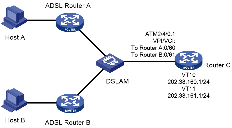
Example: Configuring PPPoA
Network configuration
As shown in Figure 7, two hosts dial into the ATM network each through an ADSL router, and communicate with Router C through DSLAM. This configuration example has the following requirements:
· Create VT for multiuser on Router C, and configure PPP mapping on VT.
· The VPI/VCI values of two PVCs connecting Router C and DSLAM are 0/60 and 0/61, pointing to ADSL Router A and ADSL Router B, respectively.
· Both the WAN port of Router C and the DSL interfaces of the two ADSL routers use PPPoA. PPP authentication is not performed. The IP addresses of the two ADSL routers are assigned by Router C.
Procedure
1. Configure Router C (PPPoA server):
# Create VT interfaces and configure IP addresses for them. Assign IP addresses to the remote ends.
<RouterC> system-view
[RouterC] interface virtual-template 10
[RouterC-Virtual-Template10] ip address 202.38.160.1 255.255.255.0
[RouterC-Virtual-Template10] remote address 202.38.162.1
[RouterC-Virtual-Template10] quit
[RouterC] interface virtual-template 11
[RouterC-Virtual-Template11] ip address 202.38.161.1 255.255.255.0
[RouterC-Virtual-Template11] remote address 202.38.162.2
[RouterC-Virtual-Template11] quit
# Create PVCs, and enable them to carry PPP.
[RouterC] interface atm 2/4/0.1
[RouterC-ATM2/4/0.1] pvc to_adsl_a 0/60
[RouterC-ATM2/4/0.1-pvc-to_adsl_a-0/60] map ppp virtual-template 10
[RouterC-ATM2/4/0.1-pvc-to_adsl_a-0/60] quit
[RouterC-ATM2/4/0.1] pvc to_adsl_b 0/61
[RouterC-ATM2/4/0.1-pvc-to_adsl_b-0/61] map ppp virtual-template 11
2. Configure ADSL Router A (PPPoA client):
# Create a VT interface, and enable IP address negotiation.
<RouterA> system-view
[RouterA] interface virtual-template 0
[RouterA-Virtual-Template0] ip address ppp-negotiate
[RouterA-Virtual-Template0] quit
# Create a PVC, and enable it to carry PPP.
[RouterA] interface atm 2/4/0
[RouterA-ATM2/4/0] pvc pppoa 0/60
[RouterA-ATM2/4/0-pvc-pppoa-0/60] map ppp virtual-template 0
[RouterA-ATM2/4/0-pvc-pppoa-0/60] quit
[RouterA-ATM2/4/0] quit
3. Configure ADSL Router B in the same way ADSL Router A is configured.
Verifying the configuration
Both ADSL Router A and ADSL Router B can ping Router C successfully.
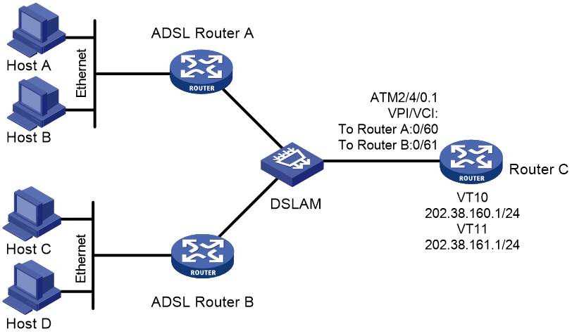
Example: Configuring PPPoEoA
Network configuration
As shown in Figure 8, the hosts in the two Ethernets are connected to the ATM network through ADSL Router A and ADSL Router B. They communicate with Router C through DSLAM.
The IP addresses of the VT interfaces of Router C are 202.38.160.1 and 202.38.161.1.
The VPI/VCI values of two PVCs connecting Router C and DSLAM are 0/60 and 0/61, pointing to ADSL Router A and ADSL Router B, respectively.
Both the WAN port of Router C and the DSL interfaces of the ADSL routers use PPPoEoA. PPP authentication is not performed. The IP addresses of the two ADSL routers are assigned by Router C.
Procedure
1. Configure Router C (PPPoEoA server):
# Create VT interfaces and configure IP addresses for them. Assign IP addresses to the remote ends.
<RouterC> system-view
[RouterC] interface virtual-template 10
[RouterC-Virtual-Template10] ip address 202.38.160.1 255.255.255.0
[RouterC-Virtual-Template10] remote address 202.38.162.1
[RouterC-Virtual-Template10] quit
[RouterC] interface virtual-template 11
[RouterC-Virtual-Template11] ip address 202.38.161.1 255.255.255.0
[RouterC-Virtual-Template11] remote address 202.38.162.2
[RouterC-Virtual-Template11] quit
# Create VEth interfaces, and enable them to carry PPP.
[RouterC] interface virtual-ethernet 1
[RouterC-Virtual-Ethernet1] pppoe-server bind virtual-template 10
[RouterC-Virtual-Ethernet1] quit
[RouterC] interface virtual-ethernet 2
[RouterC-Virtual-Ethernet2] pppoe-server bind virtual-template 11
[RouterC-Virtual-Ethernet2] quit
# Create PVCs, and enable them to carry PPPoE.
[RouterC] interface atm 2/4/0.1
[RouterC-ATM2/4/0.1] pvc to_adsl_a 0/60
[RouterC-ATM2/4/0.1-pvc-to_adsl_a-0/60] map bridge virtual-ethernet 1
[RouterC-ATM2/4/0.1-pvc-to_adsl_a-0/60] quit
[RouterC-ATM2/4/0.1] pvc to_adsl_b 0/61
[RouterC-ATM2/4/0.1-pvc-to_adsl_b-0/61] map bridge virtual-ethernet 2
2. Configure ADSL Router A (PPPoEoA client):
# Create dialer access group 1 and configure a dial access rule for it.
<RouterA> system-view
[RouterA] dialer-group 1 rule ip permit
# Create dialer interface Dialer 1 and enable bundle DDR on the interface.
[RouterA] interface dialer 1
[RouterA-Dialer1] dialer bundle enable
# Assign interface Dialer 1 to dialer access group 1.
[RouterA-Dialer1] dialer-group 1
# Configure the PPPoE client to operate in permanent online mode.
[RouterA-Dialer1] dialer timer idle 0
# Set the auto-dial interval of DDR to 1 second.
[RouterA-Dialer1] dialer timer autodial 1
# Enable IP address negotiation.
[RouterA-Dialer1] ip address ppp-negotiate
[RouterA-Dialer1] quit
# Create a VEth interface and enable it to carry PPP.
[RouterA] interface virtual-ethernet 2
[RouterA-Virtual-Ethernet2] pppoe-client dial-bundle-number 1
[RouterA-Virtual-Ethernet2] quit
# Create a PVC and enable it to carry PPPoE.
[RouterA] interface atm 2/4/0
[RouterA-ATM2/4/0] pvc 0/60
[RouterA-ATM2/4/0-pvc-0/60] map bridge virtual-ethernet 2
3. Configure ADSL Router B in the same way ADSL Router A is configured.
Verifying the configuration
Both ADSL Router A and ADSL Router B can ping Router C successfully.
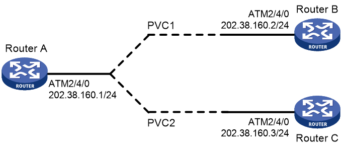
Example: Configuring ATM PVC transmission priority
Network configuration
As shown in Figure 9, create PVC 1 and PVC 2 on the same ATM 155 Mbps interface. Each PVC is assigned 100 Mbps of bandwidth and is associated with the UBR service. Set the transmission priority of PVC 1 to 1 and that of PVC 2 to 3.
Configure Router A to distribute equal amount of traffic to Router B and Router C on the two PVCs and observe the statistics of received/sent/dropped packets.
Procedure
# Configure the ATM interface.
<RouterA> system-view
[RouterA] interface atm 2/4/0
[RouterA-Atm2/4/0] ip address 202.38.160.1 255.255.255.0
# Create two PVCs, and assign them different transmission priorities.
[RouterA-ATM2/4/0] pvc 1 0/33
[RouterA-ATM2/4/0-pvc-1-0/33] map ip 202.38.160.2
[RouterA-ATM2/4/0-pvc-1-0/33] service ubr 100000
[RouterA-ATM2/4/0-pvc-1-0/33] transmit-priority 1
[RouterA-ATM2/4/0-pvc-1-0/33] quit
[RouterA-ATM2/4/0] pvc 2 0/32
[RouterA-ATM2/4/0-pvc-2-0/32] map ip 202.38.160.3
[RouterA-ATM2/4/0-pvc-2-0/32] service ubr 100000
[RouterA-ATM2/4/0-pvc-2-0/32] transmit-priority 3
Verying the configuration
After two equal amount of traffic exceeding the ATM bandwidth are sent to Router B and Router C, you can use the display atm pvc-info command on Router B and Router C to view statistics of each PVC. You can make several tests and observe the average statistics. The output shows that the PVC with higher priority receives more packets than that with lower priority. The PVC with the higher priority takes preference in getting bandwidth. Other PVCs, regardless of their priority values, are treated equally in terms of bandwidth allocation.
Troubleshooting ATM
Link state error in IPoA application
Symptom
When IPoA is used, the link state is down.
Solution
· Verify that the optical fiber is connected correctly.
· Verify that the local IP address is configured.
· Verify that the PVC is successfully created.
Link report error in PPPoA application
Symptom
When PPPoA is used, the link cannot be up.
Solution
· Verify that the optical fiber is connected correctly.
· Verify that the local IP address is configured.
· Verify that the PVC is successfully created.
Ping failure
Symptom
The physical layer of the interfaces and the line protocol are both up, but they cannot ping each other.
Solution
· If IPoA is used, make sure the IP protocol address mapping is configured correctly. If the interfaces of two routers are connected back-to-back, the local PVC mapped to the remote IP address must have the same VPI/VCI value as the remote PVC mapped to the local IP address.
· If two routers are connected back-to-back, make sure at least one of interfaces uses internal transmission clock (master). If the routers are connected to the ATM network, the transmission clock must be set to line clock (slave).
· Verify that the ATM interfaces of the two sides are of the same type. For example, both sides use multi-mode fiber interfaces, single-mode fiber interfaces, or multi-mode fiber interfaces but connected using single-mode fiber. If a multi-mode fiber interface and a single-mode fiber interface are directly connected, they can communicate in most cases, but sometimes with frequent packet dropping and CRC errors.
· If the two ends use PPPoA, make sure their IP addresses and authentication parameters are correctly configured.
· If the output from the ping command shows that only small packets can pass, check the MTU settings of both router interfaces.
PVC state is down when ATM interface state is up
Symptom
The state of the ATM interface is up, but the PVC state is down.
Solution
Determine if this fault results from enabling OAM F5 Loopback cell transmission and retransmission detection. When two routers are connected, the VPI/VCI values of the PVCs on the two routers must be the same. If OAM F5 cell transmission and retransmission detection is enabled, and the VPI/VCI values of the two directly connected nodes are not the same, the local PVC state cannot change to up.
Ping failure after PPPoA configuration
Symptom
The PVC state is up, but after applications like PPPoA are configured, the remote node cannot be pinged.
Solution
Make sure the remote node supports the same application as configured on the local node. For example, if the local node uses PPPoA, the remote node must also use PPPoA.
If the remote node supports the same application configured on the local node, make sure the two sides use the same type of AAL5 encapsulation protocol. For example, if one side uses aal5snap and the other uses aal5mux, they cannot communicate. You can enable ATM packet debugging to get some clues about possible causes of the ping failure.