- Table of Contents
- Related Documents
-
| Title | Size | Download |
|---|---|---|
| 02-Installing the device | 1002.94 KB |
Contents
Mounting the device on a workbench
Mounting the device in a 19-inch rack
Connecting the grounding cable
(Optional) Installing network port lightning protectors
(Optional) Installing a surge protected power strip
Connecting Ethernet cables for the WTU ports
Connecting Ethernet cables for the uplink port
Connecting optical fibers for the fiber ports
Connecting the device to the network
2 Installing the device
|
|
IMPORTANT: · To avoid fan tray noises, install the device in the equipment room. Do not install it in the corridor or rest area. · Keep the tamper-proof seal on a mounting screw on the chassis cover intact, and if you want to open the chassis, contact H3C for permission. Otherwise, H3C shall not be liable for any consequence. |
Installation prerequisites
· You have read "Preparing for installation" carefully.
· All requirements in "Preparing for installation" are met.
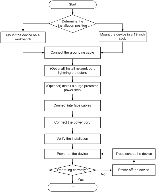
Installation flowchart
Figure2-1 Installation flowchart
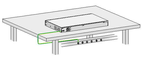
Mounting the device on a workbench
|
|
CAUTION: · Make sure the workbench is in the equipment room. · Do not place heavy objects on the device. |
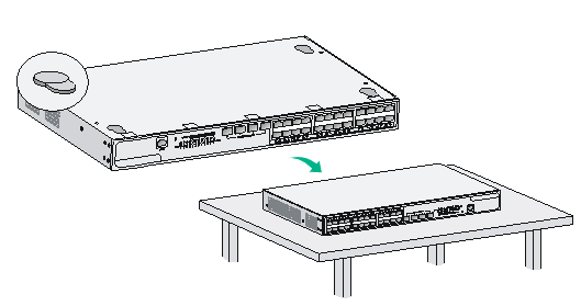
To mount the device on a workbench:
1. Place the device upside down on the workbench. Use a cloth to clean the recessed areas on the bottom.
2. Attach rubber feet to the four recessed areas.
3. Place the device upside up on the workbench.
Figure2-2 Mounting the device on a workbench
Mounting the device in a 19-inch rack
|
|
IMPORTANT: · Make sure the rack is in the equipment room. · Reserve a clearance of 44.45 mm (1.75 in)/1U between devices in a rack for heat dissipation. |
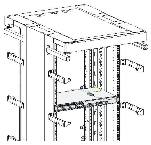
To mount the device in a 19-inch rack:
1. Wear an ESD wrist strap and make sure the rack is sturdy and is reliably grounded.
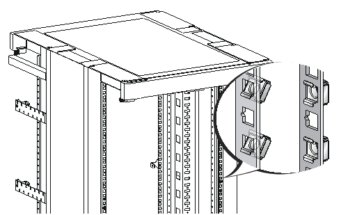
2. Use a mounting bracket to mark the cage nut installation positions on the front rack posts. Install cage nuts.
Figure2-3 Installing cage nuts
3. Use the M4 screws supplied with the mounting brackets to attach the mounting brackets to both sides of the device.
Figure2-4 Attaching the mounting brackets to the device

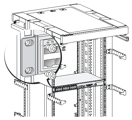
4. Supporting the bottom of the device with one hand and holding the front of the device with the other, push the device slowly into the rack. Use M6 screws and cage nuts to secure the mounting brackets to the front rack posts, as shown in Figure2-5. Make sure the device is reliably installed in the rack.
Figure2-5 Installing the device in the rack
Connecting the grounding cable
|
|
CAUTION: · Correctly connecting the grounding cable is crucial to lightning protection and EMI protection. To install and use the device, first connect the grounding cable for the device reliably. · Connect the grounding cable to the grounding system in the equipment room. Do not connect it to a fire main or lightning rod. |
To connect the grounding cable:
1. Use a Phillips screwdriver to remove the grounding screw from the grounding hole in the rear panel of the chassis.
2. Use the grounding screw to attach the ring terminal of the grounding cable to the grounding hole. Use the Phillips screwdriver to fasten the screw.
3. Connect the other end of the grounding cable to a grounding strip. Make sure the grounding strip is reliably grounded.
Figure2-6 Connecting the grounding cable for the device
(Optional) Installing network port lightning protectors
|
|
IMPORTANT: · Before installing a network port lightning protector, read the instructions in the document that comes with the protector. · Network port lightning protectors are available only for 10M/100M/1000M RJ-45 Ethernet copper ports. · If multiple network ports have network cables routed outdoors, install a network port lightning protector for each network port. |
If part of the network cable for a network port is routed outdoors, install a network port lightning protector for the port to protect against damages caused by lightning strikes.
No network port lightning protectors are provided with the device. Purchase them yourself as required.
To install a network port lightning protector for a network port:
1. Use a double-faced adhesive tape to stick the network port lightning protector onto the device chassis, and make sure it is as close to the grounding screw of the device as possible.
2. Cut the ground wire of the protector to a length (as short as possible) as required by the distance between the protector and the grounding screw of the device. Attach the ground wire securely to the grounding screw of the device.
Make sure the grounding screw of the device is reliably grounded.
3. Use a multimeter to verify that the ground wire of the protector makes good contact with the grounding screw of the chassis.
4. Insert the outdoor network cable into the protector's Surge end, and insert the cable from the network port into the Protect end.
5. Examine the port LED to verify that the port is operating correctly.
Figure2-7 Installing a lightning protector for a network port
(Optional) Installing a surge protected power strip
|
|
CAUTION: To use a surge protected power strip, make sure its PE terminal is reliably grounded. |
If you use an AC power line routed from outdoors for the device, use a surge protected power strip for the device to protect against damages caused by lightning strikes.
No surge protected power strip is provided with the device. Prepare one yourself.
To install a surge protected power strip:
1. Attach the surge protected power strip to the workbench or wall of the equipment room.
2. Connect the AC power line routed from outdoors to the IEC standard socket on the power strip.
3. Connect the AC power cord from the device to a multifunctional socket on the power strip.
Make sure the neutral wire, live wire, and earth wire of the power cord are connected to the socket holes correctly.
4. Verify that the green LED on the strip is on and the red LED is off.
5. If the red LED is on, use a multimeter to check the polarity of the wires in the power socket for incorrect connections. If the zero wire (left) and the live wire (right) are correctly connected, check for missing grounding connections.
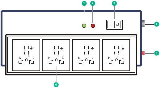
Figure2-8 Surge protected power strip
|
(1) LED (green) |
· On—The electric circuit is operating correctly. · Off—The electric circuit is damaged. |
|
(2) Grounding/pole detection LED (red) |
On indicates a wrong wire connection. The earth wire is not grounded, or the live line and neutral line are reversely connected. |
|
(3) Power switch |
|
|
(4) IEC standard socket |
For connecting the AC power line routed from outdoors. |
|
(5) Overload automatic protector |
Automatically switches off the strip when the current exceeds the threshold and returns the strip to service after the current drops below the threshold. |
|
(6) Multifunctional socket |
For connecting the power cord of the device. |
Installing interface cables
Connecting Ethernet cables for the WTU ports
|
|
IMPORTANT: You can connect a WTU port only to a WTU. |
To connect an Ethernet cable for a WTU port:
1. Connect one end of the Ethernet cable to the WTU port.
2. Connect the other end of the cable to a WTU.
3. Observe the LED for the WTU port to verify that the cable is connected correctly. For information about WTU LEDs, see "Appendix B LEDs."
Connecting Ethernet cables for the uplink port
1. Connect one end of the Ethernet cable to the uplink port.
2. Connect the other end of the cable to an Ethernet port on the peer device.
3. Observe the LED for the uplink port to verify that the cable is connected correctly. For information about the uplink LED, see "Appendix B LEDs."
Connecting optical fibers for the fiber ports
|
|
WARNING! Never stare into any disconnected optical fiber or fiber port, because invisible rays emitted from the optical fiber or fiber port might hurt your eyes. |
|
|
CAUTION: · To connect a fiber port by using an optical fiber, first insert a transceiver module into the port and then connect the optical fiber to the transceiver module. · Insert a dust plug in any open fiber port, fiber connector, or transceiver module port. · The bend radius of an optical fiber must be not less than 10 cm (3.94 in). · Keep the fiber end clean. · Make sure the Tx and Rx ports on a transceiver module are connected to the Rx and Tx ports on the peer end, respectively. |
No transceiver modules are provided with the device. Purchase transceiver modules yourself as required. For transceiver module specifications, see "Appendix A Chassis views and technical specifications."
The fiber ports on the device support only LC connectors.
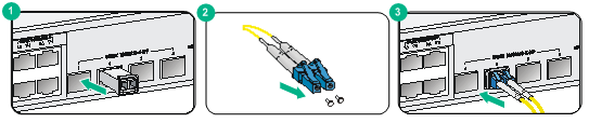
To connect an optical fiber for a fiber port:
1. Insert the transceiver module end without a pull latch into the fiber port.
2. Remove the dust plugs from the fiber connectors of the optical fiber.
3. Identify the Rx and Tx ports on the transceiver module. Use the optical fiber to connect the Rx port and Tx port on the transceiver module to the Tx port and Rx port on the peer end, respectively.
Figure2-9 Connecting an optical fiber
4. Examine the port LEDs:
¡ If the LED is on, a fiber link has been set up.
¡ If the LED is off, the link has not been set up. The reason might be wrong connection of the Tx and Rx ends. Swap the fiber connectors in the Tx and Rx ports at one end of the fiber.
Connecting the power cord
|
|
CAUTION: · Before connecting the power cord, make sure the device is reliably grounded. · To avoid bodily injury, connect the power cord first to the device and then to the equipment room power supply system. · Use the power cord and power adapter provided with the device. |
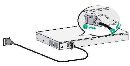
To connect the power cord:
1. Attach the power cord clasp to the device. Pivot the clasp rightwards.
2. Connect one end of the power cord to the AC power receptacle on the device.
3. Pivot the clasp rightwards to secure the AC power cord in position.
4. Connect the other end of the AC power cord to the power source.
Figure2-10 Connecting the power cord for the device
Verifying the installation
Verify the following items before you power on the device:
· There is enough space around the device for heat dissipation.
· The grounding cable, power cord, and interface cables are connected correctly.
· If part of the network cable for a port is routed outdoors, verify that a network port lightning protector is used for the port.
· If the power line is routed from outdoors, verify that a surge protected power strip is used for the device.
Connecting the device to the network
The uplink port is used for connecting the device to the Internet or WAN.
You do not need to perform configurations on the device. All the configurations for the device are performed on the AC. You can use the display wlan ap all command to view the state of the device. If the state of the device is R/M, the device has established a data tunnel with the AC and has been connected to the network.
<AC> display wlan ap all
Total number of APs: 2053
Total number of connected APs: 4
Total number of connected configured APs: 4
Total number of connected auto APs: 0
Total number of connected anchor APs: 0
Maximum AP capacity: 12288
Remaining AP capacity: 12284
Maximum AP license: 2048
Remaining AP license: 2048
Maximum WTU license: 4
Remaining WTU license: 1
AP information
State : I = Idle, J = Join, JA = JoinAck, IL = ImageLoad
C = Config, DC = DataCheck, R = Run, M = Master, B = Backup
AP name AP ID State Model Serial ID
--------------------------------------------------------------------------------
ap1 1 R/M WTU430 219801A0SS9154G00148
ap2 2 R/M WTU430 219801A0SS9154G00029
ap3 3 R/M WT1020 219801A0TA9156Q00010
ap4 4 R/M WTU430 219801A0SSC141000009
