- Table of Contents
-
- 10-Network Management and Monitoring Configuration Guide
- 00-Preface
- 01-System maintenance and debugging configuration
- 02-NQA configuration
- 03-NTP configuration
- 04-PoE configuration
- 05-SNMP configuration
- 06-RMON configuration
- 07-Event MIB configuration
- 08-NETCONF configuration
- 09-CWMP configuration
- 10-EAA configuration
- 11-Process monitoring and maintenance configuration
- 12-Mirroring configuration
- 13-sFlow configuration
- 14-Information center configuration
- 15-Packet capture configuration
- Related Documents
-
| Title | Size | Download |
|---|---|---|
| 04-PoE configuration | 134.02 KB |
Enabling nonstandard PD detection
Configuring a PD detection mode
Configuring the maximum PI power
Configuring PI power management
Configuring PSE power monitoring
Configuring a PI by using a PoE profile
Upgrading PSE firmware in service
Displaying and maintaining PoE
Failure to set the priority of a PI to critical
Failure to apply a PoE profile to a PI
Configuring PoE
Overview
Power over Ethernet (PoE) enables a network device to supply power to terminals over twisted pair cables. The device supports IEEE 802.3af and IEEE 802.3at.
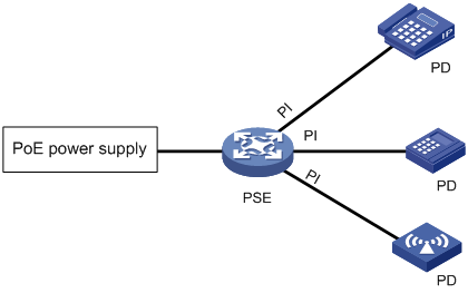
As shown in Figure 1, a PoE system includes the following elements:
· PoE power supply—The PoE power supply provides power for the entire PoE system.
· PSE—A power sourcing equipment (PSE) detects and classifies powered devices (PDs), supplies power to PDs, and monitors the PD power and connection status. PSEs include endpoint PSEs and midspan PSEs.
PSEs for the device are endpoint PSEs. A PSE can be a device with only one built-in PSE, or it can be a PoE-capable interface card or subcard on a device. A device with multiple PSEs uses PSE IDs to identify different PSEs. The display poe device command displays the mapping between a PSE ID and the slot or subslot number of a PSE.
· PI—A power interface (PI) is a PoE-capable Ethernet interface on a PSE.
· PD—A PD receives power from the PSE.
PDs include IP telephones, APs, portable chargers, POS terminals, and Web cameras.
You can also connect a PD to a redundant power source for reliability.
PoE configuration task list
You can configure a PI directly on the port or by configuring a PoE profile and applying the PoE profile to the PI. To configure one PI, configure it on the port. To configure multiple PIs in batches, use the PoE profile.
For PoE or the PoE configuration to take effect, make sure the PoE power supply and PSE are operating correctly before configuring PoE.
To configure PoE, perform the following tasks:
|
Tasks at a glance |
|
(Optional.) Configuring PD detection |
|
(Optional.) Configuring PI power management |
|
(Optional.) Configuring PSE power monitoring |
|
(Optional.) Configuring a PI by using a PoE profile: |
|
(Optional.) Upgrading PSE firmware in service |
Enabling PoE for a PI
After you enable PoE for a PI, the PI supplies power to the connected PD if the PI will not result in PSE power overload. PSE overload occurs when the sum of the power consumption of all PIs exceeds the maximum power of the PSE.
If the PI will result in PSE power overload, the following restrictions apply:
· If PI power management is not enabled, the PI does not supply power to the connected PD.
· If PI power management is enabled, whether the PDs can be powered depends on the priority of the PI.
For more information about PI power management, see "Configuring PI power management."
The power transmission over the Category 3 or Category 5 twisted pair cable can be implemented in either of the following modes:
· Over signal wires—Uses data pairs (pins 1, 2, 3, and 6) for power transmission.
· Over spare wires—Uses spare pairs (pins 4, 5, 7, and 8) for power transmission.
|
|
NOTE: · The device supports power transmission only over signal wires. · A PSE can supply power to a PD directly only when the PSE and PD use the same power transmission mode. If the PSE and PD use different power transmission modes, you must change the order of the lines in the twisted pair cable to supply power to the PD. |
To enable PoE for a PI:
|
Step |
Command |
Remarks |
|
1. Enter system view. |
system-view |
N/A |
|
1. Enter PI view. |
interface interface-type interface-number |
N/A |
|
2. Enable PoE for the PI. |
poe enable |
By default, PoE is disabled for a PI. |
|
3. (Optional.) Configure a description for the PD connected to the PI. |
poe pd-description text |
By default, no description is configured for the PD connected to the PI. |
Configuring PD detection
Enabling nonstandard PD detection
PDs are classified into standard PDs and nonstandard PDs. Standard PDs are compliant with IEEE 802.3af and IEEE 802.3at. PSEs can detect and supply power to nonstandard PDs only after you enable nonstandard PD detection.
To enable nonstandard PD detection:
|
Step |
Command |
Remarks |
|
1. Enter system view. |
system-view |
N/A |
|
2. Enable nonstandard PD detection. |
poe legacy enable pse pse-id |
By default, nonstandard PD detection is disabled. The PSE detects only IEEE 802.3af-compliant and 802.3at-compliant standard PDs and supplies power to them. |
Configuring a PD detection mode
The device detects PDs in one of the following modes:
· None—The device supplies power to PDs that are correctly connected to the device without causing short circuit.
· Simple—The device supplies power to PDs that comply with basic requirements of 802.3af or 802.3at.
· Strict—The device supplies power to PDs that comply with all requirements of 802.3af or 802.3at.
|
|
CAUTION: A non-PD device might be damaged when power is supplied to it. To avoid device damage, do not specify the none mode when the PI connects to a non-PD device. |
To detect nonstandard PDs, you must first enable detection for nonstandard PDs by using the poe legacy enable command.
To configure the PD detection mode:
|
Step |
Command |
Remarks |
|
1. Enter system view. |
system-view |
N/A |
|
2. Enter PI view. |
interface interface-type interface-number |
N/A |
|
3. Configure the PD detection mode. |
poe detection-mode { none | simple | strict } |
By default, the PD detection mode is strict. |
Configuring the maximum PI power
The maximum PI power is the maximum power that a PI can provide to the connected PD. If the PD requires more power than the maximum PI power, the PI does not supply power to the PD.
To configure the maximum PI power:
|
Step |
Command |
Remarks |
|
1. Enter system view. |
system-view |
N/A |
|
2. Enter PI view. |
interface interface-type interface-number |
N/A |
|
3. Configure the maximum power for the PI. |
poe max-power max-power |
By default, the maximum PI power is 30000 milliwatts. |
Configuring PI power management
PI power management enables the PSE to perform priority-based PI power management in PSE power overload situations. The power-supply priority levels of a PI are critical, high, and low in descending order. The PD priority is determined by the priority of the PI to which the PD is connected. All PSEs use the same PI power management mechanism.
If you do not enable PI power management, the PSE performs operations based on the status of the maximum PSE power upon power overload:
|
Maximum PSE power |
PSE operations |
|
Configured |
The PSE stops power supply to the new PD. |
|
Not configured |
The PSE stops power supply to all PDs when the PoE self-protection mechanism is triggered. |
If you enable PI power management, the PSE stops power supply to existing PDs causing overload or performs priority-based operations for new PDs causing overload:
|
Priority of the new PD |
PSE operations |
|
Low |
The PSE does not supply power to a new PD. |
|
High |
· If low-priority PDs exist, the PSE stops power supply to the existing low-priority PDs, and supplies power to the new PD. · If no low-priority PDs exist, the PSE does not supply power to the new PD. |
|
Critical |
· If low-priority or high-priority PDs exist, the PSE stops power supply to the existing low-priority or high-priority PDs, and supplies power to the new PD. · If no low-priority or high-priority PDs exist, the PSE does not supply power to the new PD. |
|
|
NOTE: Configuration for PIs whose power is preempted remains unchanged. |
If multiple new PDs require power supply, the PSE supplies power to PDs in priority descending order. For PDs with the same priority, the one with the smallest PD ID takes precedence.
If multiple existing PDs need to be stopped with power supply, the PSE stops power supply to PDs in priority ascending order. For PDs with the same priority, the one with the greatest ID takes precedence.
The PSE guarantees its critical PIs uninterruptable power by reserving guaranteed PSE power. If you want a PI to be allocated with uninterruptable power, configure the PI with critical priority. Otherwise, configure the PI with high or low priority to ensure that other PIs can be supplied with power.
Before you configure a PI with critical priority, make sure the remaining guaranteed power is greater than or equal to the maximum power of the PI. The remaining guaranteed PSE power is the maximum PSE power minus the maximum power for PoE-enabled and PoE-disabled critical PIs.
To configure PI power management:
|
Step |
Command |
Remarks |
|
1. Enter system view. |
system-view |
N/A |
|
2. Enable PI power management. |
poe pd-policy priority |
By default, PI power management is disabled. |
|
3. Enter PI view. |
interface interface-type interface-number |
N/A |
|
4. (Optional.) Configure the power supply priority for a PI. |
poe priority { critical | high | low } |
By default, the power supply priority for the PSE is low. |
Configuring PSE power monitoring
The system monitors PSE power utilization and sends notification messages when PSE power utilization exceeds or drops below the threshold. If PSE power utilization crosses the threshold multiple times in succession, the system sends notification messages only for the first crossing. For more information about the notification message, see "Configuring SNMP."
To configure a PSE power alarm threshold:
|
Step |
Command |
Remarks |
|
1. Enter system view. |
system-view |
N/A |
|
2. Configure a power alarm threshold for the PSE. |
poe utilization-threshold utilization-threshold-value pse pse-id |
By default, the power alarm threshold for the PSE is 80%. |
Configuring a PI by using a PoE profile
A PoE profile is a collection of configurations that contain multiple PoE features.
You can configure a PI either on the port or by using a PoE profile. Follow these guidelines when you configure parameters for a PI:
· The poe max-power max-power and poe priority { critical | high | low } commands must be configured in the same method.
· If you configure a parameter twice with different methods, only the first configuration takes effect.
The PoE profile is preferable for PI configuration in batches and PD-specific PI configuration.
· You can apply a PoE profile to multiple PIs. PIs configured by the same PoE profile have the same PoE features.
· You can define PoE configurations for a PD in a PoE profile, and apply the PoE profile to the PI to which the PD connects. This avoids reconfiguration when the PD is moved to another PI.
Configuring a PoE profile
|
Step |
Command |
Remarks |
|
1. Enter system view. |
system-view |
N/A |
|
2. Create a PoE profile, and enter PoE profile view. |
poe-profile profile-name [ index ] |
By default, no PoE profiles exist. |
|
3. Enable PoE. |
poe enable |
By default, this function is disabled. |
|
4. (Optional.) Configure the maximum PI power. |
poe max-power max-power |
By default, the maximum PI power is 30000 milliwatts. |
|
5. (Optional.) Configure PI priority. |
poe priority { critical | high | low } |
The default priority is low. |
Applying a PoE profile
You can apply a PoE profile in system view or PI view. If you perform the operation in both views, the most recent operation takes effect. To apply a PoE profile to multiple PIs, perform the operation in system view. A PoE profile can be applied to multiple PIs, but a PI can have only one PoE profile.
To modify an applied PoE profile, first execute the undo apply poe-profile or undo apply poe-profile interface command to remove its application.
Applying a PoE profile to multiple PIs in system view
|
Step |
Command |
Remarks |
|
1. Enter system view. |
system-view |
N/A |
|
2. Apply a PoE profile to one or multiple PIs. |
apply poe-profile { index index | name profile-name } interface interface-range |
By default, no PoE profile is applied to a PI. |
Applying a PoE profile to a PI in PI view
|
Step |
Command |
Remarks |
|
1. Enter system view. |
system-view |
N/A |
|
2. Enter PI view. |
interface interface-type interface-number |
N/A |
|
3. Apply the PoE profile to the interface. |
apply poe-profile { index index | name profile-name } |
By default, no PoE profile is applied to a PI. |
Upgrading PSE firmware in service
You can upgrade the PSE firmware in service in either of the following modes:
· Refresh mode—Updates the PSE firmware without deleting it. You can use the refresh mode in most cases.
· Full mode—Deletes the current PSE firmware and reloads a new one. Use the full mode if the PSE firmware is damaged and you cannot execute any PoE commands.
If the PSE firmware upgrade fails because of interruption such as a device reboot, you can restart the device and upgrade it in full mode again. After the upgrade, restart the device manually for the new PSE firmware to take effect.
To upgrade the PSE firmware in service:
|
Step |
Command |
|
1. Enter system view. |
system-view |
|
2. Upgrade the PSE firmware in service. |
poe update { full | refresh } filename [ pse pse-id ] |
Displaying and maintaining PoE
Execute display commands in any view.
|
Task |
Command |
|
Display general PSE information. |
display poe device [ slot slot-number ] |
|
Display the power supplying information for the specified PI. |
display poe interface [ interface-type interface-number ] |
|
Display power information for PIs. |
display poe interface power [ interface-type interface-number ] |
|
Display detailed PSE information. |
display poe pse [ pse-id ] |
|
Display the power supplying information for all PIs on a PSE. |
display poe pse pse-id interface |
|
Display power information for all PIs on a PSE. |
display poe pse pse-id interface power |
|
Display all information about the PoE profile. |
display poe-profile [ index index | name profile-name ] |
|
Display all information about the PoE profile applied to the specified PI. |
display poe-profile interface interface-type interface-number |
PoE configuration example
Network requirements
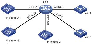
As shown in Figure 2, configure PoE to meet the following requirements:
· Enable the device to supply power to IP telephones and APs.
· Enable the device to supply power to IP telephones first when overload occurs.
· Allocate AP B a maximum power of 9000 milliwatts.
Configuration procedure
# Enable PI power management.
<PSE> system-view
[PSE] poe pd-policy priority
# Enable PoE for the PSE.
[PSE] poe enable pse 4
# Enable PoE on GigabitEthernet 1/0/1, GigabitEthernet 1/0/2, and GigabitEthernet 1/0/3, and configure their power supply priority as critical.
[PSE] interface gigabitethernet 1/0/1
[PSE-GigabitEthernet1/0/1] poe enable
[PSE-GigabitEthernet1/0/1] poe priority critical
[PSE-GigabitEthernet1/0/1] quit
[PSE] interface gigabitethernet 1/0/2
[PSE-GigabitEthernet1/0/2] poe enable
[PSE-GigabitEthernet1/0/2] poe priority critical
[PSE-GigabitEthernet1/0/2] quit
[PSE] interface gigabitethernet 1/0/3
[PSE-GigabitEthernet1/0/3] poe enable
[PSE-GigabitEthernet1/0/3] poe priority critical
[PSE-GigabitEthernet1/0/3] quit
# Enable PoE on GigabitEthernet 1/0/4 and GigabitEthernet 1/0/5, and set the maximum power of GigabitEthernet 1/0/5 to 9000 milliwatts.
[PSE] interface gigabitethernet 1/0/4
[PSE-GigabitEthernet1/0/4] poe enable
[PSE-GigabitEthernet1/0/4] quit
[PSE] interface gigabitethernet 1/0/5
[PSE-GigabitEthernet1/0/5] poe enable
[PSE-GigabitEthernet1/0/5] poe max-power 9000
Verifying the configuration
# Connect the IP telephones and APs to the PSE to verify that they can obtain power and operate correctly. (Details not shown.)
Troubleshooting PoE
Failure to set the priority of a PI to critical
Symptom
Power supply priority configuration for a PI failed.
Solution
To resolve the problem:
1. Identify whether the remaining guaranteed power of the PSE is lower than the maximum power of the PI. If it is, increase the maximum PSE power or reduce the maximum power of the PI.
2. Identify whether the priority has been configured through other methods. If the priority has been configured, remove the configuration.
3. If the problem persists, contact H3C Support.
Failure to apply a PoE profile to a PI
Symptom
PoE profile application for a PI failed.
Solution
To resolve the problem:
1. Identify whether some settings in the PoE profile have been configured. If they have been configured, remove the configuration.
2. Identify whether the settings in the PoE profile meet the requirements of the PI. If they do not, modify the settings in the PoE profile.
3. Identify whether another PoE profile is already applied to the PI. If it is, remove the application.
4. If the problem persists, contact H3C Support.