- Table of Contents
- Related Documents
-
| Title | Size | Download |
|---|---|---|
| 03-Data buffer configuration | 104.19 KB |
Configuring data buffers manually
Setting the maximum shared-area ratio for a queue
Setting the fixed-area ratio for a queue
Applying data buffer configuration
Displaying and maintaining data buffers
Configuring data buffers
Data buffers temporarily store packets to avoid packet loss.
A device has an ingress buffer and an egress buffer. Figure 1 shows the structure of ingress and egress buffers. An interface stores outgoing packets in the egress buffer when congestion occurs, and stores incoming packets in the ingress buffer when the CPU is busy.
Figure 1 Data buffer structure
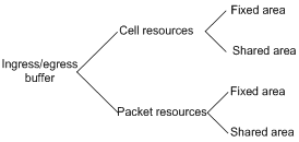
A buffer uses the following types of resources:
· Cell resources—Store packets. The buffer uses cell resources based on packet sizes. Suppose a cell resource provides 208 bytes. The buffer allocates one cell resource to a 128-byte packet and two cell resources to a 300-byte packet.
· Packet resources—Store packet pointers. A packet pointer indicates where the packet is located in cell resources. The buffer uses one packet resource for each incoming or outgoing packet.
Each type of resources has a fixed area and a shared area.
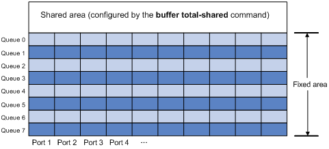
· Fixed area—Partitioned into queues, each of which is equally divided by all the interfaces on the switch, as shown in Figure 2. When congestion occurs, the following rules apply:
a. An interface first uses the relevant queues of the fixed area to store packets.
b. When a queue is full, the interface uses the corresponding queue of the shared area.
c. When the queue in the shared area is also full, the interface discards subsequent packets.
The system allocates the fixed area among queues as specified by the user. Even if a queue is not full, other queues cannot preempt its space. Similarly, the share of a queue for an interface cannot be preempted by other interfaces even if it is not full.
· Shared area—Partitioned into queues, each of which is not equally divided by the interfaces, as shown in Figure 2. The system determines the actual shared-area space for each queue according to user configuration and the number of packets actually received and sent. If a queue is not full, other queues can preempt its space.
The system puts packets received on all interfaces into a queue in the order they arrive. When the queue is full, subsequent packets are dropped.
Figure 2 Fixed area and shared area
Configuration task list
You can configure data buffers either automatically by enabling the Burst feature or manually.
If you have configured data buffers in one way, delete the configuration before using the other way. Otherwise, the new configuration does not take effect.
|
Tasks at a glance |
|
Perform one of the following tasks: · Configuring data buffers manually ¡ Setting the shared-area ratio ¡ Setting the maximum shared-area ratio for a queue |
Enabling the Burst feature
The Burst feature enables the device to automatically allocate cell and packet resources. It is well suited to the following scenarios:
· Broadcast or multicast traffic is intensive, resulting in bursts of traffic.
· Traffic comes in and goes out in one of the following ways:
¡ Enters a device from a high-speed interface and goes out of a low-speed interface.
¡ Enters from multiple same-rate interfaces at the same time and goes out of an interface with the same rate.
To enable the Burst feature:
|
Step |
Command |
Remarks |
|
1. Enter system view. |
system-view |
N/A |
|
2. Enable the Burst feature. |
burst-mode enable |
By default, the Burst feature is disabled. |
Configuring data buffers manually
|
|
CAUTION: To avoid impact to the system, do not manually change data buffer settings to avoid impact to the system. If large buffer spaces are needed, use the Burst feature. |
The switch supports configuring only cell resources.
Setting the shared-area ratio
After you set the shared-area ratio, the rest is automatically assigned to the fixed area.
To set the shared-area ratio:
|
Step |
Command |
Remarks |
|
system-view |
N/A |
|
|
2. Set the shared-area ratio. |
buffer egress [ slot slot-number ] cell total-shared ratio ratio |
The default setting is 97%. |
Setting the maximum shared-area ratio for a queue
By default, all queues have an equal share of the shared area. This task allows you to change the maximum shared-area ratio for a queue. The other queues use the default setting.
The actual maximum shared-area space for each queue is determined by the chip based on your configuration and the number of packets to be received and sent.
To set the maximum shared-area ratio for a queue:
|
Step |
Command |
Remarks |
|
1. Enter system view. |
system-view |
N/A |
|
2. Set the maximum shared-area ratio for a queue. |
buffer egress [ slot slot-number ] cell queue queue-id shared ratio ratio |
The default setting is 33%. |
Setting the fixed-area ratio for a queue
By default, all queues have an equal share of the fixed area. This task allows you to change the fixed-area ratio for a queue. The other queues equally share the remaining part.
The fixed-area space for a queue cannot be used by other queues. Therefore, it is also called the minimum guaranteed buffer for the queue. The sum of fixed-area ratios configured for all queues cannot exceed the total fixed-area ratio. Otherwise, the configuration fails.
To set the fixed-area ratio for a queue:
|
Step |
Command |
Remarks |
|
1. Enter system view. |
system-view |
N/A |
|
2. Set the fixed-area ratio for a queue. |
buffer egress [ slot slot-number ] cell queue queue-id guaranteed ratio ratio |
The default setting is 12%. |
Applying data buffer configuration
Perform this task to apply the data buffer configuration.
You cannot directly modify the applied configuration. To modify the configuration, you must cancel the application, reconfigure data buffers, and reapply the configuration.
To apply data buffer configuration:
|
Step |
Command |
|
1. Enter system view. |
system-view |
|
2. Apply data buffer configuration. |
buffer apply |
Displaying and maintaining data buffers
Execute display commands in any view.
|
Task |
Command |
|
Display buffer size settings. |
display buffer [ slot slot-number ] [ queue [ queue-id ] ] |
|
Display data buffer usage. |
display buffer usage [ slot slot-number ] |
Burst configuration example
Network requirements
As shown in Figure 3, a server connects to the switch through a 1000 Mbps Ethernet interface. The server sends high-volume broadcast or multicast traffic to the hosts irregularly. Each host connects to the switch through a 100 Mbps network adapter.
Configure the switch to process high-volume traffic from the server to guarantee that packets can reach the hosts.

Configuration procedure
# Enter system view.
<Switch> system-view
# Enable the Burst feature.
[Switch] burst-mode enable