- Table of Contents
- Related Documents
-
| Title | Size | Download |
|---|---|---|
| 04-Data buffer configuration | 94.81 KB |
Configuring data buffers
An interface stores outgoing packets in the egress buffer when congestion occurs.
An egress buffer uses the following types of resources:
· Cell resources—Store packets. The buffer uses cell resources based on packet sizes. Suppose a cell resource provides 208 bytes. The buffer allocates one cell resource to a 128-byte packet and two cell resources to a 300-byte packet.
· Packet resources—Store packet pointers. A packet pointer indicates where the packet is located in cell resources. The buffer uses one packet resource for each incoming or outgoing packet.
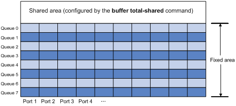
Each type of resources has a fixed area and a shared area.
· Fixed area—Partitioned into queues, each of which is equally divided by all the interfaces on a device, as shown in Figure 1. When congestion occurs, the following rules apply:
a. An interface first uses the relevant queues of the fixed area to store packets.
b. When a queue is full, the interface uses the space for the queue in the shared area.
c. When the queue in the shared area is also full, the interface discards subsequent packets.
The system allocates the fixed area among queues as specified by the user. Even if a queue is not full, other queues cannot preempt its space. Similarly, the share of a queue for an interface cannot be preempted by other interfaces even if it is not full.
· Shared area—Partitioned into queues, each of which is not equally divided by the interfaces, as shown in Figure 1. The system determines the actual shared-area ratio for each queue according to user configuration and the number of packets actually sent. If a queue is not full, other queues can preempt its space.
The system puts packets received on all interfaces into a queue in the order they arrive. When the queue is full, subsequent packets are dropped.
Figure 1 Fixed area and shared area
Configuration task list
|
Tasks at a glance |
|
(Required.) Enabling the Burst feature |
|
(Optional.) Configuring data buffer monitoring |
Enabling the Burst feature
The Burst feature enables the device to automatically allocate cell and packet resources. It is well suited to the following scenarios:
· Broadcast or multicast traffic is intensive, resulting in bursts of traffic.
· Traffic enters and goes out in one of the following ways:
? Enters from a high-speed interface and goes out of a low-speed interface.
? Enters from multiple same-rate interfaces at the same time and goes out of an interface with the same rate.
By enabling the Burst feature, you can improve the processing performance of the switch operating in these scenarios to reduce packet loss.
The Burst feature might affect the QoS performance of the switch.
Configuration prerequisites
Make sure you are fully aware of the impact when enabling the Burst feature.
Configuration procedure
To enable the Burst feature:
|
Step |
Command |
Remarks |
|
1. Enter system view. |
system-view |
N/A |
|
2. Enable the Burst feature. |
burst-mode enable |
By default, the Burst feature is disabled. |
Burst configuration example
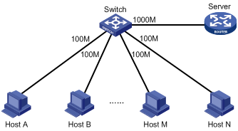
Network requirements
As shown in Figure 2, a server connects to the switch through a 1000 Mbps Ethernet interface. The server sends high-volume broadcast or multicast traffic to the hosts irregularly. Each host connects to the switch through a 100 Mbps network adapter.
Configure the switch to process high-volume traffic from the server to guarantee that packets can reach the hosts.
Configuration procedure
# Enter system view.
<Switch> system-view
# Enable the burst feature.
[Switch] burst-mode enable
Configuring data buffer monitoring
The data buffer on a switch is shared by all interfaces for buffering packets during periods of congestion.
This feature allows you to identify the interfaces that use an excessive amount of data buffer space. Then, you can diagnose those interfaces for anomalies.
You can set a per-interface buffer usage threshold. The buffer usage threshold for a queue is the same as the per-interface threshold value. The switch automatically records buffer usage for each interface. When a queue on an interface uses more buffer space than the set threshold, the system counts one threshold violation for the queue.
To configure data buffer monitoring:
|
Step |
Command |
Remarks |
|
1. Enter system view. |
system-view |
N/A |
|
2. Set the packet statistics collection mode to queue. |
statistic mode queue |
The default setting is vsi. For more information about packet statistics collection modes, see "Configuring queue-based accounting." |
|
3. Set a per-interface buffer usage threshold. |
·
In standalone mode: ·
In IRF mode: |
The default setting is 100%. |
|
4. Return to user view. |
quit |
N/A |
|
5. Display buffer usage statistics for interfaces. |
display buffer usage interface [ interface-type [ interface-number ] ] |
Available in any view. |