- Table of Contents
-
- 04-Layer 3-IP Services Configuration Guide
- 00-Preface
- 01-ARP configuration
- 02-IP addressing configuration
- 03-DHCP configuration
- 04-DNS configuration
- 05-IP forwarding basics configuration
- 06-IRDP configuration
- 07-IP performance optimization configuration
- 08-UDP Helper configuration
- 09-IPv6 basics configuration
- 10-DHCPv6 configuration
- 11-Tunnel configuration
- 12-GRE configuration
- Related Documents
-
| Title | Size | Download |
|---|---|---|
| 11-Tunnel configuration | 193.07 KB |
Contents
Tunneling configuration task list
Configuring a tunnel interface
Configuring an IPv6 over IPv4 tunnel
IPv6 over IPv4 tunnel configuration example
Configuring an IPv4 over IPv4 tunnel
IPv4 over IPv4 tunnel configuration example
Displaying and maintaining tunneling configuration
Configuring tunneling
Overview
Tunneling is an encapsulation technology. One network protocol encapsulates packets of another network protocol and transfers them over a virtual point-to-point connection. The virtual connection is called a tunnel. Packets are encapsulated at the tunnel source end and de-encapsulated at the tunnel destination end. Tunneling refers to the whole process from data encapsulation to data transfer to data de-encapsulation.
Tunneling supports the following technologies:
· Transition techniques, such as IPv6 over IPv4 tunneling, to interconnect IPv4 and IPv6 networks.
· VPN, such as IPv4 over IPv4 tunneling, IPv4/IPv6 over IPv6 tunneling, GRE, DVPN, and IPsec tunneling.
· Traffic engineering, such as MPLS TE to prevent network congestion.
Unless otherwise specified, the term "tunnel" in this document refers to IPv6 over IPv4 and IPv4 over IPv4 tunnels.
IPv6 over IPv4 tunneling
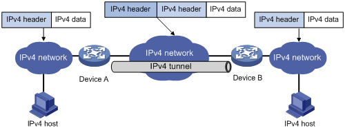
IPv6 over IPv4 tunneling enables isolated IPv6 networks to communicate, as shown in Figure 1.
|
|
NOTE: The devices at the ends of an IPv6 over IPv4 tunnel must support the IPv4/IPv6 dual stack. |
Figure 1 IPv6 over IPv4 tunnel

The IPv6 over IPv4 tunnel processes packets by using the following steps:
1. A host in the IPv6 network sends an IPv6 packet to Device A at the tunnel source.
a. Searches the routing table to identify the outgoing interface for the IPv6 packet.
The outgoing interface is the tunnel interface, so Device A knows that the packet needs to be forwarded through the tunnel.
b. Encapsulates the IPv6 packet with an IPv4 header and forwards it through the physical interface of the tunnel.
In the IPv4 header, the source IPv4 address is the IPv4 address of the tunnel source, and the destination IPv4 address is the IPv4 address of the tunnel destination.
2. Upon receiving the packet, Device B de-encapsulates the packet.
3. If the destination address of the IPv6 packet is itself, Device B forwards it to the upper-layer protocol. If not, Device B forwards it according to the routing table.
IPv4 over IPv4 tunneling
IPv4 over IPv4 tunneling (RFC 1853) enables isolated IPv4 networks to communicate. For example, an IPv4 over IPv4 tunnel can connect isolated private IPv4 networks over a public IPv4 network.
Figure 2 IPv4 over IPv4 tunnel
Packets traveling through a tunnel undergo encapsulation and de-encapsulation, as shown in Figure 2.
· Encapsulation:
a. Device A receives an IP packet from an IPv4 host and submits it to the IP protocol stack.
b. The IPv4 protocol stack determines how to forward the packet according to the destination address in the IP header. If the packet is destined for the IPv4 host connected to Device B, Device A delivers the packet to the tunnel interface.
c. The tunnel interface adds a new IPv4 header to the IPv4 packet and submits it to the IP protocol stack. In the new header, the source IP address specifies the tunnel source, and the destination IP address specifies the tunnel destination. The IP protocol stack uses the destination IP address of the new IP header to look up the routing table, and then sends the packet out.
· De-encapsulation:
a. After receiving the packet, Device B delivers it to the IP protocol stack.
b. If the protocol number is 4 (indicating an IPv4 packet is encapsulated within the packet), the IP protocol stack delivers the packet to the tunnel module for de-encapsulation.
c. The tunnel module de-encapsulates the IP packet and sends it back to the IP protocol stack.
d. The protocol stack forwards the de-encapsulated packet.
Protocols and standards
· RFC 1853, IP in IP Tunneling
· RFC 2473, Generic Packet Tunneling in IPv6 Specification
· RFC 2893, Transition Mechanisms for IPv6 Hosts and Routers
· RFC 3056, Connection of IPv6 Domains via IPv4 Clouds
Tunneling configuration task list
|
Tasks at a glance |
|
(Required.) Configuring a tunnel interface |
|
Perform either of the following tasks: |
Configuring a tunnel interface
Before you create a tunnel interface, you must reserve global resources of two VLAN interfaces. The device uses the reserved resources to create the tunnel interface. For more information about global VLAN interface resource reservation, see Layer 2—LAN Switching Configuration Guide.
The device cannot directly route a tunneled packet based on the packet's destination address. The packet is sent to a tunnel-type service loopback group, which then delivers the packet to the forwarding module for Layer 3 forwarding. For the tunnel interface to correctly receive and forward packets, you must configure a tunnel-type service loopback group. For information about service loopback group, see Layer 2—LAN Switching Configuration Guide.
Configure a tunnel interface (Layer 3 virtual interface) at both ends of a tunnel. The devices use the tunnel interface to identify, process, and send packets for the tunnel.
To configure a tunnel interface:
|
Step |
Command |
Remarks |
|
1. Enter system view. |
system-view |
N/A |
|
2. Reserve global VLAN interface resources. |
reserve-vlan-interface vlan-interface-id1 [ to vlan-interface-id2 ] global |
By default, no reserved VLAN interface resources exist. |
|
3. Create a service loopback group and specify its service type as tunnel. |
service-loopback group number type tunnel |
By default, no service loopback groups exist. |
|
4. Enter Layer 2 Ethernet interface view. |
interface interface-type interface-number |
N/A |
|
5. Assign the port to the service loopback group. |
port service-loopback group number |
By default, a port does not belong to a service loopback group. |
|
6. Return to system view. |
quit |
N/A |
|
7. Create a tunnel interface, specify the tunnel mode, and enter tunnel interface view. |
interface tunnel number mode { evi | gre | ipv4-ipv4 | ipv6-ipv4 | mpls-te | vxlan } |
By default, no tunnel interface is created. When you create a new tunnel interface, you must specify the tunnel mode. When you enter the view of an existing tunnel interface, you do not need to specify the tunnel mode. To ensure successful packet tunneling, the two ends of a tunnel must use the same tunnel mode. The supported tunnel mode varies by system operating mode. For more information about setting the system operating mode, see Fundamentals Configuration Guide. |
|
8. (Optional.) Configure a description for the interface. |
description text |
By default, the description for a tunnel interface is Tunnel number Interface. |
|
9. (Optional.) Specify a traffic processing card for the tunnel interface. |
·
In standalone mode: ·
In IRF mode: |
By default, no traffic processing card is specified. |
|
10. Set the MTU of the tunnel interface. |
mtu size |
The default MTU is 64000 bytes. |
|
11. Set the expected bandwidth for the tunnel interface. |
bandwidth bandwidth-value |
By default, the expected bandwidth is 64 kbps. The expected bandwidth for the tunnel interface affects the link cost value. For more information, see Layer 3—IP Routing Configuration Guide. |
|
12. Set the ToS for tunneled packets. |
tunnel tos tos-value |
The default setting is the same as the ToS of the original packet. |
|
13. Set the TTL for tunneled packets. |
tunnel ttl ttl-value |
The default TTL for tunneled packets is 255. |
|
14. Specify the VPN instance to which the tunnel destination belongs. |
tunnel vpn-instance vpn-instance-name |
By default, the tunnel destination belongs to the public network. For the tunnel interface to come up, the tunnel source and destination must belong to the same VPN. To specify a VPN instance for the tunnel source, use the ip binding vpn-instance command on the tunnel source interface. For more information about the ip binding vpn-instance command, see MPLS Command Reference. |
|
15. (Optional.) Restore the default settings of the tunnel interface. |
default |
N/A |
|
16. (Optional.) Shut down the tunnel interface. |
shutdown |
By default, the tunnel interface is enabled. |
Configuring an IPv6 over IPv4 tunnel
Follow these guidelines when you configure an IPv6 over IPv4 tunnel:
· Before you create a tunnel interface, you must reserve global resources of two VLAN interfaces. The device uses the reserved resources to create the tunnel interface. For more information about global VLAN interface resource reservation, see Layer 2—LAN Switching Configuration Guide.
· The device cannot directly route a tunneled packet based on the packet's destination address. The packet is sent to a tunnel-type service loopback group, which then delivers the packet to the forwarding module for Layer 3 forwarding. For the tunnel interface to correctly receive and forward packets, you must configure a tunnel-type service loopback group. For information about service loopback group, see Layer 2—LAN Switching Configuration Guide.
· The tunnel destination address specified on the local device must be identical with the tunnel source address specified on the tunnel peer device.
· Do not specify the same tunnel source and destination addresses for the tunnels in the same mode on a device.
· To ensure correct packet forwarding, identify whether the destination IPv6 network and the IPv6 address of the local tunnel interface are on the same subnet. If they are not, configure a route reaching the destination IPv6 network through the tunnel interface. You can configure the route by using one of the following methods:
¡ Configure a static route, and specify the local tunnel interface as the egress interface or specify the IPv6 address of the peer tunnel interface as the next hop.
¡ Enable IPv6 BGP on the tunnel interface.
The route configuration is required on both ends of the tunnel. For more information about the route configuration, see IPv6 static routing or BGP in Layer 3—IP Routing Configuration Guide.
To configure an IPv6 over IPv4 tunnel:
|
Step |
Command |
Remarks |
|
1. Enter system view. |
system-view |
N/A |
|
2. Reserve global VLAN interface resources. |
reserve-vlan-interface vlan-interface-id1 [ to vlan-interface-id2 ] global |
By default, no reserved VLAN interface resources exist. |
|
3. Create a service loopback group and specify its service type as tunnel. |
service-loopback group number type tunnel |
By default, no service loopback groups exist. |
|
4. Enter Layer 2 Ethernet interface view. |
interface interface-type interface-number |
N/A |
|
5. Assign the port to the service loopback group. |
port service-loopback group number |
By default, a port does not belong to a service loopback group. |
|
6. Return to system view. |
quit |
N/A |
|
7. Enter IPv6 over IPv4 tunnel interface view. |
interface tunnel number [ mode ipv6-ipv4 ] |
N/A |
|
8. Specify an IPv6 address for the tunnel interface. |
See "Configuring basic IPv6 settings." |
By default, no IPv6 address is configured for the tunnel interface. |
|
9. Configure a source address or source interface for the tunnel interface. |
source { ip-address | interface-type interface-number } |
By default, no source address or source interface is configured for the tunnel interface. If you specify a source address, it is used as the source IP address of tunneled packets. If you specify a source interface, the primary IP address of this interface is used as the source IP address of tunneled packets. |
|
10. Configure a destination address for the tunnel interface. |
destination ip-address |
By default, no destination address is configured for the tunnel interface. The tunnel destination address must be the IP address of the receiving interface on the tunnel peer. It is used as the destination IP address of tunneled packets. |
|
11. Return to system view. |
quit |
N/A |
|
12. (Optional.) Enable dropping of IPv6 packets using IPv4-compatible IPv6 addresses. |
tunnel discard ipv4-compatible-packet |
By default, this feature is disabled. |
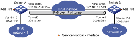
IPv6 over IPv4 tunnel configuration example
Network requirements
As shown in Figure 3, configure an IPv6 over IPv4 tunnel between Switch A and Switch B so the two IPv6 networks can reach each other over the IPv4 network.
Configuration procedure
Make sure Switch A and Switch B have the corresponding VLAN interfaces created and can reach each other through IPv4.
1. Configure Switch A:
# Specify an IPv4 address for VLAN-interface 100.
<SwitchA> system-view
[SwitchA] interface vlan-interface 100
[SwitchA-Vlan-interface100] ip address 192.168.100.1 255.255.255.0
[SwitchA-Vlan-interface100] quit
# Specify an IPv6 address for VLAN-interface 101.
[SwitchA] interface vlan-interface 101
[SwitchA-Vlan-interface101] ipv6 address 3002::1 64
[SwitchA-Vlan-interface101] quit
# Reserve global resources of VLAN-interface 3001 and VLAN-interface 3002.
[SwitchA] reserve-vlan-interface 3001 to 3002 global
# Create service loopback group 1 and specify its service type as tunnel.
[SwitchA] service-loopback group 1 type tunnel
# Add FortyGigE 1/0/3 to service loopback group 1.
[SwitchA] interface FortyGigE 1/0/3
[SwitchA-FortyGigE1/0/3] port service-loopback group 1
[SwitchA-FortyGigE1/0/3] quit
# Create IPv6 over IPv4 tunnel interface Tunnel 0.
[SwitchA] interface tunnel 0 mode ipv6-ipv4
# Specify an IPv6 address for the tunnel interface.
[SwitchA-Tunnel0] ipv6 address 3001::1/64
# Specify VLAN-interface 100 as the source interface of the tunnel interface.
[SwitchA-Tunnel0] source vlan-interface 100
# Specify the destination address for the tunnel interface as the IP address of the VLAN-interface 100 on Switch B.
[SwitchA-Tunnel0] destination 192.168.50.1
[SwitchA-Tunnel0] quit
# Configure a static route destined for IPv6 network 2 through Tunnel 0.
[SwitchA] ipv6 route-static 3003:: 64 tunnel 0
2. Configure Switch B:
# Specify an IPv4 address for VLAN-interface 100.
<SwitchB> system-view
[SwitchB] interface vlan-interface 100
[SwitchB-Vlan-interface100] ip address 192.168.50.1 255.255.255.0
[SwitchB-Vlan-interface100] quit
# Specify an IPv6 address for VLAN-interface 101.
[SwitchB] interface vlan-interface 101
[SwitchB-Vlan-interface101] ipv6 address 3003::1 64
[SwitchB-Vlan-interface101] quit
# Reserve global resources of VLAN-interface 3001 and VLAN-interface 3002.
[SwitchB] reserve-vlan-interface 3001 to 3002 global
# Create service loopback group 1 and specify its service type as tunnel.
[SwitchB] service-loopback group 1 type tunnel
# Add FortyGigE 1/0/3 to service loopback group 1.
[SwitchB] interface FortyGigE 1/0/3
[SwitchB-FortyGigE1/0/3] port service-loopback group 1
[SwitchB-FortyGigE1/0/3] quit
# Create IPv6 over IPv4 tunnel interface Tunnel 0.
[SwitchB] interface tunnel 0 mode ipv6-ipv4
# Specify an IPv6 address for the tunnel interface.
[SwitchB-Tunnel0] ipv6 address 3001::2/64
# Specify VLAN-interface 100 as the source interface of the tunnel interface.
[SwitchB-Tunnel0] source vlan-interface 100
# Specify the destination address for the tunnel interface as the IP address of VLAN-interface 100 of Switch A.
[SwitchB-Tunnel0] destination 192.168.100.1
[SwitchB-Tunnel0] quit
# Configure a static route destined for IPv6 network 1 through Tunnel 0.
[SwitchB] ipv6 route-static 3002:: 64 tunnel 0
Verifying the configuration
# Use the display ipv6 interface command to display tunnel interface status on Switch A and Switch B. Verify that the interface Tunnel 0 is up. (Details not shown.)
# Verify that Switch B and Switch A can ping the IPv6 address of VLAN-interface 101 of each other. This example uses Switch A.
[SwitchA] ping ipv6 3003::1
Ping6(56 data bytes) 3001::1 --> 3003::1, press CTRL_C to break
56 bytes from 3003::1, icmp_seq=0 hlim=64 time=45.000 ms
56 bytes from 3003::1, icmp_seq=1 hlim=64 time=10.000 ms
56 bytes from 3003::1, icmp_seq=2 hlim=64 time=4.000 ms
56 bytes from 3003::1, icmp_seq=3 hlim=64 time=10.000 ms
56 bytes from 3003::1, icmp_seq=4 hlim=64 time=11.000 ms
--- Ping6 statistics for 3003::1 ---
5 packet(s) transmitted, 5 packet(s) received, 0.0% packet loss
round-trip min/avg/max/std-dev = 4.000/16.000/45.000/14.711 ms
Configuring an IPv4 over IPv4 tunnel
Follow these guidelines when you configure an IPv4 over IPv4 tunnel:
· Before you create a tunnel interface, you must reserve global resources of two VLAN interfaces. The device uses the reserved resources to create the tunnel interface. For more information about global VLAN interface resource reservation, see Layer 2—LAN Switching Configuration Guide.
· The device cannot directly route a tunneled packet based on the packet's destination address. The packet is sent to a tunnel-type service loopback group, which then delivers the packet to the forwarding module for Layer 3 forwarding. For the tunnel interface to correctly receive and forward packets, you must configure a tunnel-type service loopback group. For information about service loopback group, see Layer 2—LAN Switching Configuration Guide.
· The destination address specified for the local tunnel interface must be the source address specified for the peer tunnel interface.
· The source/destination addresses of local tunnels of the same tunnel mode cannot be the same.
· The IPv4 address of the local tunnel interface cannot be on the same subnet as the destination address configured on the tunnel interface.
· To ensure correct packet forwarding, identify whether the destination IPv4 network and the IPv4 address of the local tunnel interface are on the same subnet. If they are not, configure a route reaching the destination IPv4 network through the tunnel interface. You can configure the route by using one of the following methods:
¡ Configure a static route, and specify the local tunnel interface as the egress interface or specify the IPv4 address of the peer tunnel interface as the next hop.
¡ Enable BGP on the tunnel interface.
The route configuration is required on both ends of the tunnel. For more information about the route configuration, see static routing or BGP in Layer 3—IP Routing Configuration Guide.
· The destination address of the route passing the tunnel interface must not be on the same subnet as the destination address configured on the tunnel interface.
To configure an IPv4 over IPv4 tunnel:
|
Step |
Command |
Remarks |
|
1. Enter system view. |
system-view |
N/A |
|
2. Reserve global VLAN interface resources. |
reserve-vlan-interface vlan-interface-id1 [ to vlan-interface-id2 ] global |
By default, no reserved VLAN interface resources exist. |
|
3. Create a service loopback group and specify its service type as tunnel. |
service-loopback group number type tunnel |
By default, no service loopback groups exist. |
|
4. Enter Layer 2 Ethernet interface view. |
interface interface-type interface-number |
N/A |
|
5. Assign the port to the service loopback group. |
port service-loopback group number |
By default, a port does not belong to a service loopback group. |
|
6. Return to system view. |
quit |
N/A |
|
7. Enter IPv4 over IPv4 tunnel interface view. |
interface tunnel number [ mode ipv4-ipv4 ] |
N/A |
|
8. Configure an IPv4 address for the tunnel interface. |
ip address ip-address { mask | mask-length } [ sub ] |
By default, no IPv4 address is configured for the tunnel interface. |
|
9. Configure a source address or source interface for the tunnel interface. |
source { ip-address | interface-type interface-number } |
By default, no source address or source interface is configured for the tunnel interface. If you specify a source address, it is used as the source IP address of tunneled packets. If you specify a source interface, the primary IP address of this interface is used as the source IP address of tunneled packets. |
|
10. Configure a destination address for the tunnel interface. |
destination ip-address |
By default, no destination address is configured for the tunnel interface. The tunnel destination address must be the IP address of the receiving interface on the tunnel peer. It is used as the destination IP address of tunneled packets. |
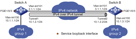
IPv4 over IPv4 tunnel configuration example
Network requirements
As shown in Figure 4, the two subnets IPv4 group 1 and IPv4 group 2 use private IPv4 addresses. Configure an IPv4 over IPv4 tunnel between Switch A and Switch B so the two subnets can reach each other.
Configuration procedure
Make sure Switch A and Switch B have the corresponding VLAN interfaces created and can reach each other through IPv4.
1. Configure Switch A:
# Specify an IPv4 address for VLAN-interface 100.
<SwitchA> system-view
[SwitchA] interface vlan-interface 100
[SwitchA-Vlan-interface100] ip address 10.1.1.1 255.255.255.0
[SwitchA-Vlan-interface100] quit
# Specify an IPv4 address for VLAN-interface 101, which is the physical interface of the tunnel.
[SwitchA] interface vlan-interface 101
[SwitchA-Vlan-interface101] ip address 2.1.1.1 255.255.255.0
[SwitchA-Vlan-interface101] quit
# Reserve global resources of VLAN-interface 3001 and VLAN-interface 3002.
[SwitchA] reserve-vlan-interface 3001 to 3002 global
# Create service loopback group 1 and specify its service type as tunnel.
[SwitchA] service-loopback group 1 type tunnel
# Assign FortyGigE 1/0/3 to service loopback group 1.
[SwitchA] interface FortyGigE 1/0/3
[SwitchA-FortyGigE1/0/3] port service-loopback group 1
[SwitchA-FortyGigE1/0/3] quit
# Create IPv4 over IPv4 tunnel interface Tunnel 1.
[SwitchA] interface tunnel 1 mode ipv4-ipv4
# Specify an IPv4 address for the tunnel interface.
[SwitchA-Tunnel1] ip address 10.1.2.1 255.255.255.0
# Specify the IP address of VLAN-interface 101 as the source address for the tunnel interface.
[SwitchA-Tunnel1] source 2.1.1.1
# Specify the IP address of VLAN-interface 101 on Switch B as the destination address for the tunnel interface.
[SwitchA-Tunnel1] destination 3.1.1.1
[SwitchA-Tunnel1] quit
# Configure a static route destined for the IPv4 group 2 through the tunnel interface.
[SwitchA] ip route-static 10.1.3.0 255.255.255.0 tunnel 1
2. Configure Switch B:
# Specify an IPv4 address for VLAN-interface 100.
<SwitchB> system-view
[SwitchB] interface vlan-interface 100
[SwitchB-Vlan-interface100] ip address 10.1.3.1 255.255.255.0
[SwitchB-Vlan-interface100] quit
# Specify an IPv4 address for VLAN-interface 101, which is the physical interface of the tunnel.
[SwitchB] interface vlan-interface 101
[SwitchB-Vlan-interface101] ip address 3.1.1.1 255.255.255.0
[SwitchB-Vlan-interface101] quit
# Reserve global resources of VLAN-interface 3001 and VLAN-interface 3002.
[SwitchB] reserve-vlan-interface 3001 to 3002 global
# Create service loopback group 1 and specify its service type as tunnel.
[SwitchB] service-loopback group 1 type tunnel
# Assign FortyGigE 1/0/3 to service loopback group 1.
[SwitchB] interface FortyGigE 1/0/3
[SwitchB-FortyGigE1/0/3] port service-loopback group 1
[SwitchB-FortyGigE1/0/3] quit
# Create IPv4 over IPv4 tunnel interface Tunnel 2.
[SwitchB] interface tunnel 2 mode ipv4-ipv4
# Specify an IPv4 address for the tunnel interface.
[SwitchB-Tunnel2] ip address 10.1.2.2 255.255.255.0
# Specify the IP address of VLAN-interface 101 as the source address for the tunnel interface.
[SwitchB-Tunnel2] source 3.1.1.1
# Specify the IP address of VLAN-interface 101 on Switch A as the destination address for the tunnel interface.
[SwitchB-Tunnel2] destination 2.1.1.1
[SwitchB-Tunnel2] quit
# Configure a static route destined for the IPv4 group 1 through the tunnel interface.
[SwitchB] ip route-static 10.1.1.0 255.255.255.0 tunnel 2
Verifying the configuration
# Use the display interface tunnel command to display the status of the tunnel interfaces on Switch A and Switch B. Verify that the tunnel interfaces are up. (Details not shown.)
# Verify that Switch A and Switch B can ping the IPv4 address of the peer interface VLAN-interface 100. This example uses Switch A.
[SwitchA] ping -a 10.1.1.1 10.1.3.1
Ping 10.1.3.1 (10.1.3.1) from 10.1.1.1: 56 data bytes, press CTRL_C to break
56 bytes from 10.1.3.1: icmp_seq=0 ttl=255 time=2.000 ms
56 bytes from 10.1.3.1: icmp_seq=1 ttl=255 time=1.000 ms
56 bytes from 10.1.3.1: icmp_seq=2 ttl=255 time=0.000 ms
56 bytes from 10.1.3.1: icmp_seq=3 ttl=255 time=1.000 ms
56 bytes from 10.1.3.1: icmp_seq=4 ttl=255 time=1.000 ms
--- Ping statistics for 10.1.3.1 ---
5 packet(s) transmitted, 5 packet(s) received, 0.0% packet loss
round-trip min/avg/max/std-dev = 0.000/1.000/2.000/0.632 ms
Displaying and maintaining tunneling configuration
Execute display commands in any view and reset commands in user view.
|
Task |
Command |
|
Display information about tunnel interfaces. |
display interface tunnel [ number [ brief [ description ] ] | brief [ description | down ] ] |
|
Display IPv6 information on tunnel interfaces. |
display ipv6 interface [ tunnel [ number ] ] [ brief ] |
|
Clear statistics on tunnel interfaces. |
reset counters interface [ tunnel [ number ] ] |
Troubleshooting tunneling
Symptom
A tunnel interface configured with related parameters such as tunnel source address, tunnel destination address, and tunnel mode cannot come up.
Analysis
The physical interface of the tunnel does not come up, or the tunnel destination is unreachable.
Solution
1. To resolve the problem:
¡ Use the display interface or display ipv6 interface command to verify that the physical interface of the tunnel is up. If the physical interface is down, check the network connection.
¡ Use the display ipv6 routing-table or display ip routing-table command to verify that the tunnel destination is reachable. If the route is not available, configure a route to reach the tunnel destination.
2. If the problem persists, contact H3C Support.