- Table of Contents
- Related Documents
-
| Title | Size | Download |
|---|---|---|
| 10-Track configuration | 364.17 KB |
Contents
Restrictions and guidelines: Track configuration
Collaboration application example·
Associating the Track module with a detection module
Associating Track with interface management
Associating Track with route management
Associating the Track module with an application module
Prerequisites for associating the Track module with an application module
Associating Track with static routing·
Associating Track with Smart Link
Display and maintenance commands for Track
Example: Configuring VRRP-Track-NQA collaboration
Example: Configuring BFD for a VRRP backup to monitor the master
Example: Configuring BFD for the VRRP master to monitor the uplinks
Example: Configuring static routing-Track-NQA collaboration
Example: Configuring static routing-Track-BFD collaboration
Example: Configuring VRRP-Track-interface management collaboration
Example: Configuring VRRP-Track-route management collaboration
Example: Configuring static routing-Track-LLDP collaboration
Example: Configuring Smart Link-Track-CFD collaboration
Configuring Track
About Track
Collaboration mechanism
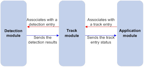
The Track module collaborates with detection modules and application modules.
As shown in Figure 1, collaboration is enabled when you associate the Track module with a detection module and an application module, and it operates as follows:
1. The detection module probes specific objects such as interface status, link status, network reachability, and network performance, and informs the Track module of detection results.
2. The Track module sends the detection results to the application module.
3. When notified of changes for the tracked object, the application modules can react to avoid communication interruption and network performance degradation.
Figure 1 Collaboration through the Track module
Collaboration between the Track module and a detection module
The detection module sends the detection result of the tracked object to the Track module. The Track module changes the status of the track entry as follows:
· If the tracked object operates correctly, the state of the track entry is Positive. For example, the track entry state is Positive in one of the following conditions:
? The target interface is up.
? The target network is reachable.
· If the tracked object does not operate correctly, the state of the track entry is Negative. For example, the track entry state is Negative in one of the following conditions:
? The target interface is down.
? The target network is unreachable.
· If the detection result is invalid, the state of the track entry is NotReady. For example, the track entry state is NotReady if its associated NQA operation does not exist.
Collaboration between the Track module and an application module
Supported detection modules
The following detection modules can be associated with the Track module:
· NQA.
· BFD.
· CFD.
· Interface management.
· Route management.
· LLDP.
Supported application modules
The following application modules can be associated with the Track module:
· VRRP.
· Static routing.
· PBR
· Smart Link.
· EAA.
· ERPS.
Restrictions and guidelines: Track configuration
When configuring a track entry for an application module, you can set a notification delay to avoid immediate notification of status changes.
When the delay is not configured and the route convergence is slower than the link state change notification, communication failures occur. For example, when the master in a VRRP group detects an uplink interface failure through Track, Track immediately notifies the master to decrease its priority. A backup with a higher priority then preempts as the new master. When the failed uplink interface recovers, the Track module immediately notifies the original master to restore its priority. If the uplink route has not recovered, forwarding failure will occur.
Collaboration application example
The following is an example of collaboration between NQA, Track, and static routing.
Configure a static route with next hop 192.168.0.88 on the device. If the next hop is reachable, the static route is valid. If the next hop becomes unreachable, the static route is invalid. For this purpose, configure NQA-Track-static routing collaboration as follows:
1. Create an NQA operation to monitor the accessibility of IP address 192.168.0.88.
2. Create a track entry and associate it with the NQA operation.
? When next hop 192.168.0.88 is reachable, NQA sends the result to the Track module. The Track module sets the track entry to Positive state.
? When the next hop becomes unreachable, NQA sends the result to the Track module. The Track module sets the track entry to Negative state.
3. Associate the track entry with the static route.
? When the track entry is in Positive state, the static routing module considers the static route to be valid.
? When the track entry is in Negative state, the static routing module considers the static route to be invalid.
Track tasks at a glance
To implement the collaboration function, establish associations between the Track module and detection modules, and between the Track module and application modules.
To configure the Track module, perform the following tasks:
1. Associating the Track module with a detection module
? Associating Track with interface management
? Associating Track with route management
2. Associating the Track module with an application module
? Associating Track with static routing
? Associating Track with Smart Link
Associating the Track module with a detection module
Associating Track with NQA
About Track association with NQA
NQA supports multiple operation types to analyze network performance and service quality. For example, an NQA operation can periodically detect whether a destination is reachable, or whether a TCP connection can be established.
An NQA operation operates as follows when it is associated with a track entry:
· If the consecutive probe failures reach the specified threshold, the NQA module notifies the Track module that the tracked object has malfunctioned. The Track module then sets the track entry to Negative state.
· If the specified threshold is not reached, the NQA module notifies the Track module that the tracked object is operating correctly. The Track module then sets the track entry to Positive state.
For more information about NQA, see Network Management and Monitoring Configuration Guide.
Restrictions and guidelines
If you associate a track entry with a nonexistent NQA operation or reaction entry, the state of the track entry is NotReady.
Procedure
1. Enter system view.
system-view
2. Create a track entry, and associate it with an NQA reaction entry.
track track-entry-number nqa entry admin-name operation-tag reaction item-number [ delay { negative negative-time | positive positive-time } * ]
Associating Track with BFD
About Track association with BFD
BFD supports the control packet mode and echo packet mode. A track entry can be associated only with the echo-mode BFD session. For more information about BFD, see "Configuring BFD."
The associated Track and BFD operate as follows:
· If the BFD detects that the link fails, it informs the Track module of the link failure. The Track module sets the track entry to Negative state.
· If the BFD detects that the link is operating correctly, the Track module sets the track entry to Positive state.
Restrictions and guidelines
When you associate a track entry with BFD, do not configure the virtual IP address of a VRRP group as the local or remote address of the BFD session.
Prerequisites
Before you associate Track with BFD, configure the source IP address of BFD echo packets. For more information, see "Configuring BFD."
Procedure
1. Enter system view.
system-view
2. Create a track entry, and associate it with a BFD session.
track track-entry-number bfd echo interface interface-type interface-number remote ip remote-ip-address local ip local-ip-address [ delay { negative negative-time | positive positive-time } * ]
Associating Track with CFD
About Track association with CFD
The associated Track and CFD operate as follows:
· If the CFD detects that the link fails, it informs the Track module of the link failure. The Track module then sets the track entry to Negative state.
· If the CFD detects that the link is operating correctly, the Track module sets the track entry to Positive state.
For more information about CFD, see "Configuring CFD."
Prerequisites
Before you associate Track with CFD, enable CFD and create a MEP. For more information, see "Configuring CFD."
Procedure
1. Enter system view.
system-view
2. Create a track entry, and associate it with CFD.
track track-entry-number cfd cc service-instance instance-id mep mep-id [ delay { negative negative-time | positive positive-time } * ]
Associating Track with interface management
About Track association with interface management
The interface management module monitors the link status or network-layer protocol status of interfaces. The associated Track and interface management operate as follows:
· When the link or network-layer protocol status of the interface changes to up, the interface management module informs the Track module of the change. The Track module sets the track entry to Positive state.
· When the link or network-layer protocol status of the interface changes to down, the interface management module informs the Track module of the change. The Track module sets the track entry to Negative state.
Procedure
1. Enter system view.
system-view
2. Create a track entry, and associate it with interface management.
? Create a track entry to monitor the link status of an interface.
track track-entry-number interface interface-type interface-number [ delay { negative negative-time | positive positive-time } * ]
? Create a track entry to monitor the physical status of an interface.
track track-entry-number interface interface-type interface-number physical [ delay { negative negative-time | positive positive-time } * ]
? Create a track entry to monitor the network layer protocol status of an interface.
track track-entry-number interface interface-type interface-number protocol { ipv4 | ipv6 } [ delay { negative negative-time | positive positive-time } * ]
Associating Track with route management
About Track association with route management
The route management module monitors route entry changes in the routing table. The associated Track and route management operate as follows:
· When a monitored route entry is found in the routing table, the route management module informs the Track module. The Track module sets the track entry to Positive state.
· When a monitored route entry is removed from the routing table, the route management module informs the Track module of the change. The Track module sets the track entry to Negative state.
Procedure
1. Enter system view.
system-view
2. Create a track entry and associate it with a route entry.
track track-entry-number ip route [ vpn-instance vpn-instance-name ] ip-address { mask-length | mask } reachability [ delay { negative negative-time | positive positive-time } * ]
Associating Track with LLDP
About Track association with LLDP
The LLDP module monitors the neighbor availability of LLDP interfaces. The associated Track and LLDP operate as follows:
· When the neighbor of the monitored LLDP interface is available, the LLDP module informs the Track module. The Track module sets the track entry to Positive state.
· When the neighbor of the monitored LLDP interface is unavailable, the LLDP module informs the Track module. The Track module sets the track entry to Negative state.
For more information about LLDP, see Layer 2—LAN Switching Configuration Guide.
Procedure
1. Enter system view.
system-view
2. Create a track entry and associate it with an LLDP interface.
track track-entry-number lldp neighbor interface interface-type interface-number [ delay { negative negative-time | positive positive-time } * ]
Associating the Track module with an application module
Before you associate the Track module with an application module, make sure the associated track entry has been created.
Prerequisites for associating the Track module with an application module
Create a track entry first before you associate it with an application module.
An application module might obtain incorrect track entry status information if the associated track entry does not exist.
Associating Track with VRRP
About Track association with VRRP
When VRRP is operating in standard mode or load balancing mode, associate the Track module with the VRRP group to implement the following actions:
· Change the priority of a router according to the status of the uplink. If a fault occurs on the uplink of the router, the VRRP group is not aware of the uplink failure. If the router is the master, hosts in the LAN cannot access the external network. To resolve this problem, configure a detection module-Track-VRRP collaboration. The detection module monitors the status of the uplink of the router and notifies the Track module of the detection result.
When the uplink fails, the detection module notifies the Track module to change the status of the monitored track entry to Negative. The priority of the master decreases by a user-specified value. A router with a higher priority in the VRRP group becomes the master.
· Monitor the master on a backup. If a fault occurs on the master, the backup operating in switchover mode will switch to the master immediately to maintain normal communication.
When VRRP is operating in load balancing mode, associate the Track module with the VRRP VF to implement the following functions:
· Change the priority of the AVF according to its uplink state. When the uplink of the AVF fails, the track entry changes to Negative state. The weight of the AVF decreases by a user-specified value. The VF with a higher priority becomes the new AVF to forward packets.
· Monitor the AVF status from the LVF. When the AVF fails, the LVF that is operating in switchover mode becomes the new AVF to ensure continuous forwarding.
For more information about configuring VRRP, see "Configuring VRRP."
Restrictions and guidelines for Track association with VRRP
· VRRP tracking does not take effect on an IP address owner. The configuration takes effect when the router does not act as the IP address owner.
An IP address owner is the router with its interface IP address used as the virtual IP address of the VRRP group.
· When the status of the track entry changes from Negative to Positive or NotReady, the associated router or VF restores its priority automatically.
Associating Track with a VRRP group
1. Enter system view.
system-view
2. Enter interface view.
interface interface-type interface-number
3. Associate a track entry with a VRRP group.
vrrp [ ipv6 ] vrid virtual-router-id track track-entry-number { forwarder-switchover member-ip ip-address | priority reduced [ priority-reduced ] switchover | weight reduced [ weight-reduced ] }
By default, no track entry is associated with a VRRP group.
This command is supported when VRRP is operating in both standard mode and load balancing mode.
Associating Track with a VRRP VF
1. Enter system view.
system-view
2. Enter interface view.
interface interface-type interface-number
3. Associate Track with a VRRP VF.
vrrp [ ipv6 ] vrid virtual-router-id track track-entry-number { forwarder-switchover member-ip ip-address | priority reduced [ priority-reduced ] switchover | weight reduced [ weight-reduced ] }
By default, no track entry is associated with a VRRP VF.
This command is configurable when VRRP is operating in standard mode or load balancing mode. However, the configuration takes effect only when VRRP is operating in load balancing mode.
Associating Track with static routing
About track association with static routing
A static route is a manually configured route to route packets. For more information about static route configuration, see Layer 3—IP Routing Configuration Guide.
Static routes cannot adapt to network topology changes. Link failures or network topological changes can make the routes unreachable and cause communication interruption.
To resolve this problem, configure another route to back up the static route. When the static route is reachable, packets are forwarded through the static route. When the static route is unreachable, packets are forwarded through the backup route.
To check the accessibility of a static route in real time, associate the Track module with the static route.
If you specify the next hop but not the output interface when configuring a static route, you can configure the static routing-Track-detection module collaboration. This collaboration enables you to verify the accessibility of the static route based on the track entry state.
· If the track entry is in Positive state, the following conditions exist:
? The next hop of the static route is reachable.
? The configured static route is valid.
· If the track entry is in Negative state, the following conditions exist:
? The next hop of the static route is not reachable.
? The configured static route is invalid.
· If the track entry is in NotReady state, the following conditions exist:
? The accessibility of the next hop of the static route is unknown.
? The static route is valid.
Restrictions and guidelines
In static routing-Track-NQA collaboration, you must configure the same VPN instance name for the NQA operation and the next hop of the static route. Otherwise, the accessibility detection cannot operate correctly.
If a static route needs route recursion, the associated track entry must monitor the next hop of the recursive route. The next hop of the static route cannot be monitored. Otherwise, a valid route might be considered invalid.
Procedure
1. Enter system view.
system-view
2. Associate a static route with a track entry to check the accessibility of the next hop.
Public network:
ip route-static { dest-address { mask-length | mask } | group group-name } { interface-type interface-number [ next-hop-address ] [ backup-interface interface-type interface-number [ backup-nexthop backup-nexthop-address ] [ permanent ] | bfd { control-packet | echo-packet } | permanent | track track-entry-number ] | next-hop-address [ recursive-lookup host-route ] [ bfd control-packet bfd-source ip-address | permanent | track track-entry-number ] | vpn-instance d-vpn-instance-name next-hop-address [ recursive-lookup host-route ] [ bfd control-packet bfd-source ip-address | permanent | track track-entry-number ] } [ preference preference ] [ tag tag-value ] [ description text ]
VPN:
ip route-static vpn-instance s-vpn-instance-name { dest-address { mask-length | mask } | group group-name } { interface-type interface-number [ next-hop-address ] [ backup-interface interface-type interface-number [ backup-nexthop backup-nexthop-address ] [ permanent ] | bfd { control-packet | echo-packet } | permanent | track track-entry-number ] | next-hop-address [ recursive-lookup host-route ] [ public ] [ bfd control-packet bfd-source ip-address | permanent | track track-entry-number ] | vpn-instance d-vpn-instance-name next-hop-address [ recursive-lookup host-route ] [ bfd control-packet bfd-source ip-address | permanent | track track-entry-number ] } [ preference preference ] [ tag tag-value ] [ description text ]
By default, Track is not associated with static routing.
Associating Track with PBR
About Track association with PBR
PBR uses user-defined policies to route packets. You can specify parameters in a PBR policy to guide the forwarding of the packets that match specific criteria. For more information about PBR, see Layer 3—IP Routing Configuration Guide.
PBR cannot detect the availability of any action taken on packets. When an action is not available, packets processed by the action might be discarded. For example, if the output interface specified for PBR fails, PBR cannot detect the failure, and continues to forward matching packets out of the interface.
To enable PBR to detect topology changes and improve the flexibility of the PBR application, configure Track-PBR-detection module collaboration.
After you associate a track entry with an apply clause, the detection module associated with the track entry sends Track the detection result of the availability of the tracked object.
· The Positive state of the track entry indicates that the object is available, and the apply clause is valid.
· The Negative state of the track entry indicates that the object is not available, and the apply clause is invalid.
· The NotReady state of the track entry indicates that the apply clause is valid.
In the current software version, you can specify only the next hop for matching packets in a PBR policy.
Prerequisites for Track association with PBR
Before you associate Track with PBR, create a policy node, and set the match criteria.
Associating Track with PBR
1. Enter system view.
system-view
2. Create a policy node and enter its view.
policy-based-route policy-name [ deny | permit ] node node-number
3. Set an ACL match criterion.
if-match acl { acl-number | name acl-name }
By default, no ACL match criterion is set.
The ACL match criterion cannot match Layer 2 information.
An ACL match criterion does not use the permit or deny action and the time range of the specified ACL to match packets.
4. Set the next hop for matching packets and associate the next hop with a track entry.
apply next-hop [ vpn-instance vpn-instance-name | inbound-vpn ] { ip-address [ direct ] [ track track-entry-number ] [ weight weight-value ] }&<1-n>
By default, no next hop is set.
Associating Track with IPv6 PBR
1. Enter system view.
system-view
2. Create an IPv6 policy node and enter its view.
ipv6 policy-based-route policy-name [ deny | permit ] node node-number
3. Set an ACL match criterion.
if-match acl { ipv6-acl-number | name ipv6-acl-name }
By default, no ACL match criterion is set.
The ACL match criterion cannot match Layer 2 information.
An ACL match criterion does not use the permit or deny action and the time range of the specified ACL to match packets.
4. Set the next hop for matching packets and associate the next hop with a track entry.
apply next-hop [ vpn-instance vpn-instance-name | inbound-vpn ] { ipv6-address [ direct ] [ track track-entry-number ] [ weight weight-value ] } &<1-n>
By default, no next hop is set.
Associating Track with Smart Link
About Track association with Smart Link
Smart Link cannot detect unidirectional links, misconnected fibers, or packet loss on intermediate devices or network paths of the uplink. It also cannot detect when faults are cleared. To check the link status, Smart Link ports must use link detection protocols. When a fault is detected or cleared, the link detection protocols inform Smart Link to switch over the links.
You can configure the collaboration between Smart Link and Track on a smart link group member port. Smart Link collaborates with the CC feature of CFD through the track entry to detect the link status on the port.
· When the track entry is in Positive state, the link is in normal state. Smart Link does not perform link switchover for the smart link group.
· When the track entry is in Negative state, the link has failed. Smart Link determines whether to perform link switchover according to the link preemption mode and port role configured in the smart link group.
· When the track entry is in NotReady state, the port state does not change.
For more information about Smart Link, see "Configuring Smart Link."
Restrictions and guidelines
The track entry to be used for collaboration with Smart Link must have been associated with the CC feature of CFD.
Procedure
1. Enter system view.
system-view
2. Enter Layer 2 Ethernet interface view or Layer 2 aggregate interface view.
interface interface-type interface-number
3. Configure collaboration between Smart Link and Track on the port.
port smart-link group group-id track track-entry-number
By default, the collaboration between Smart Link and Track is not configured.
Associating Track with EAA
About Track association with EAA
You can configure EAA track event monitor policies to monitor the positive-to-negative or negative-to-positive state changes of track entries.
· If you specify only one track entry for a policy, EAA triggers the policy when it detects the specified state change on the track entry.
· If you specify multiple track entries for a policy, EAA triggers the policy when it detects the specified state change on the last monitored track entry. For example, if you configure a policy to monitor the positive-to-negative state change of multiple track entries, EAA triggers the policy when the last positive track entry monitored by the policy is changed to the Negative state.
You can set a suppression time for a track event monitor policy. The timer starts when the policy is triggered. The system does not process messages that report the monitored track event until the timer times out.
For more information about EAA, see Network Management and Monitoring Configuration Guide.
Procedure
1. Enter system view.
system-view
2. Create a CLI-defined monitor policy and enter its view, or enter the view of an existing CLI-defined monitor policy.
rtm cli-policy policy-name
3. Configure a track event.
event track track-entry-number-list state { negative | positive } [ suppress-time suppress-time ]
By default, a monitor policy does not monitor any track event.
Associating Track with ERPS
About Track association with ERPS
To detect and clear link faults typically for a fiber link, use ERPS with CFD and Track. You can associate ERPS ring member ports with the continuity check function of CFD through track entries. CFD reports link events only when the monitored VLAN is the control VLAN of the ERPS instance for the port.
Track changes the track entry state based on the monitoring result of CFD, and notifies the track entry state change to the associated EPRS ring.
· When the track entry is in Positive state, the link of the monitored ERPS ring member port is in normal state. The ERPS ring does not switch traffic to other links.
· When the track entry is in Negative state, the link of the monitored ERPS ring member port is faulty. The ERPS ring switches traffic to other links.
· When the track entry is in NotReady state, the state of the ERPS ring member port does not change.
For more information about ERPS, see "Configuring ERPS."
Restrictions and guidelines
Before you associate a port with a track entry, make sure the port has joined an ERPS instance.
Procedure
1. Enter system view.
system-view
2. Enter Layer 2 Ethernet interface view or Layer 2 aggregate interface view.
interface interface-type interface-number
3. Associate an ERPS ring member port with a track entry.
port erps ring ring-id instance instance-id track track-entry-index
By default, an ERPS ring member port is not associated with any track entries.
Display and maintenance commands for Track
Execute display commands in any view.
|
Task |
Command |
|
Display information about track entries. |
display track { track-entry-number | all [ negative | positive ] } [ brief ] |
Track configuration examples
Example: Configuring VRRP-Track-NQA collaboration
Network configuration
As shown in Figure 2:
· Host A requires access to Host B. The default gateway of Host A is 10.1.1.10/24.
· Switch A and Switch B belong to VRRP group 1. The virtual IP address of VRRP group 1 is 10.1.1.10.
Configure VRRP-Track-NQA collaboration to monitor the uplink on the master and meet the following requirements:
· When Switch A operates correctly, Switch A forwards packets from Host A to Host B.
· When NQA detects a fault on the uplink of Switch A, Switch B forwards packets from Host A to Host B.
Procedure
1. Create VLANs and assign ports to them. Configure the IP address of each VLAN interface, as shown in Figure 2. (Details not shown.)
2. Configure an NQA operation on Switch A:
# Create an NQA operation with administrator name admin and operation tag test.
<SwitchA> system-view
[SwitchA] nqa entry admin test
# Specify the ICMP echo operation type.
[SwitchA-nqa-admin-test] type icmp-echo
# Specify 10.1.2.2 as the destination address of ICMP echo requests.
[SwitchA-nqa-admin-test-icmp-echo] destination ip 10.1.2.2
# Configure the ICMP echo operation to repeat every 100 milliseconds.
[SwitchA-nqa-admin-test-icmp-echo] frequency 100
# Configure reaction entry 1, specifying that five consecutive probe failures trigger the Track module.
[SwitchA-nqa-admin-test-icmp-echo] reaction 1 checked-element probe-fail threshold-type consecutive 5 action-type trigger-only
[SwitchA-nqa-admin-test-icmp-echo] quit
# Start the NQA operation.
[SwitchA] nqa schedule admin test start-time now lifetime forever
3. On Switch A, configure track entry 1, and associate it with reaction entry 1 of the NQA operation.
[SwitchA] track 1 nqa entry admin test reaction 1
4. Configure VRRP on Switch A:
# Specify VRRPv2 to run on VLAN-interface 2.
[SwitchA] interface vlan-interface 2
[SwitchA-Vlan-interface2] vrrp version 2
# Create VRRP group 1, and configure virtual IP address 10.1.1.10 for the group.
[SwitchA-Vlan-interface2] vrrp vrid 1 virtual-ip 10.1.1.10
# Set the priority of Switch A to 110 in VRRP group 1.
[SwitchA-Vlan-interface2] vrrp vrid 1 priority 110
# Set the authentication mode of VRRP group 1 to simple, and the authentication key to hello.
[SwitchA-Vlan-interface2] vrrp vrid 1 authentication-mode simple hello
# Configure the master to send VRRP packets every 500 centiseconds.
[SwitchA-Vlan-interface2] vrrp vrid 1 timer advertise 500
# Configure Switch A to operate in preemptive mode and set the preemption delay to 5000 centiseconds.
[SwitchA-Vlan-interface2] vrrp vrid 1 preempt-mode timer delay 5000
# Associate VRRP group 1 with track entry 1 and decrease the router priority by 30 when the state of track entry 1 changes to negative.
[SwitchA-Vlan-interface2] vrrp vrid 1 track 1 priority reduced 30
5. Configure VRRP on Switch B:
# Specify VRRPv2 to run on VLAN-interface 2.
<SwitchB> system-view
[SwitchB] interface vlan-interface 2
[SwitchB-Vlan-interface2] vrrp version 2
# Create VRRP group 1, and configure virtual IP address 10.1.1.10 for the group.
[SwitchB-Vlan-interface2] vrrp vrid 1 virtual-ip 10.1.1.10
# Set the authentication mode of VRRP group 1 to simple, and the authentication key to hello.
[SwitchB-Vlan-interface2] vrrp vrid 1 authentication-mode simple hello
# Configure the master to send VRRP packets every 500 centiseconds.
[SwitchB-Vlan-interface2] vrrp vrid 1 timer advertise 500
# Configure Switch B to operate in preemptive mode and set the preemption delay to 5000 centiseconds.
[SwitchB-Vlan-interface2] vrrp vrid 1 preempt-mode timer delay 5000
Verifying the configuration
# Ping Host B from Host A to verify that Host B is reachable. (Details not shown.)
# Display detailed information about VRRP group 1 on Switch A.
[SwitchA-Vlan-interface2] display vrrp verbose
IPv4 Virtual Router Information:
Running Mode : Standard
Total number of virtual routers : 1
Interface Vlan-interface2
VRID : 1 Adver Timer : 500
Admin Status : Up State : Master
Config Pri : 110 Running Pri : 110
Preempt Mode : Yes Delay Time : 5000
Auth Type : Simple Key : ******
Virtual IP : 10.1.1.10
Virtual MAC : 0000-5e00-0101
Master IP : 10.1.1.1
VRRP Track Information:
Track Object : 1 State : Positive Pri Reduced : 30
# Display detailed information about VRRP group 1 on Switch B.
[SwitchB-Vlan-interface2] display vrrp verbose
IPv4 Virtual Router Information:
Running Mode : Standard
Total number of virtual routers : 1
Interface Vlan-interface2
VRID : 1 Adver Timer : 500
Admin Status : Up State : Backup
Config Pri : 100 Running Pri : 100
Preempt Mode : Yes Delay Time : 5000
Become Master : 2200ms left
Auth Type : Simple Key : ******
Virtual IP : 10.1.1.10
Master IP : 10.1.1.1
The output shows that in VRRP group 1, Switch A is the master, and Switch B is a backup. Switch A forwards packets from Host A to Host B.
# Disconnect the link between Switch A and Switch C, and verify that Host A can still ping Host B. (Details not shown.)
# Display detailed information about VRRP group 1 on Switch A.
[SwitchA-Vlan-interface2] display vrrp verbose
IPv4 Virtual Router Information:
Running Mode : Standard
Total number of virtual routers : 1
Interface Vlan-interface2
VRID : 1 Adver Timer : 500
Admin Status : Up State : Backup
Config Pri : 110 Running Pri : 80
Preempt Mode : Yes Delay Time : 5000
Become Master : 2200ms left
Auth Type : Simple Key : ******
Virtual IP : 10.1.1.10
Master IP : 10.1.1.2
VRRP Track Information:
Track Object : 1 State : Negative Pri Reduced : 30
# Display detailed information about VRRP group 1 on Switch B.
[SwitchB-Vlan-interface2] display vrrp verbose
IPv4 Virtual Router Information:
Running Mode : Standard
Total number of virtual routers : 1
Interface Vlan-interface2
VRID : 1 Adver Timer : 500
Admin Status : Up State : Master
Config Pri : 100 Running Pri : 100
Preempt Mode : Yes Delay Time : 5000
Auth Type : Simple Key : ******
Virtual IP : 10.1.1.10
Virtual MAC : 0000-5e00-0101
Master IP : 10.1.1.2
The output shows that Switch A becomes the backup, and Switch B becomes the master. Switch B forwards packets from Host A to Host B.
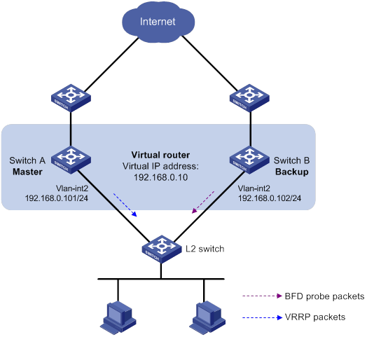
Example: Configuring BFD for a VRRP backup to monitor the master
Network configuration
As shown in Figure 3:
· Switch A and Switch B belong to VRRP group 1. The virtual IP address of VRRP group 1 is 192.168.0.10.
· The default gateway of the hosts in the LAN is 192.168.0.10.
Configure VRRP-Track-BFD collaboration to monitor the master on the backup and meet the following requirements:
· When Switch A operates correctly, the hosts in the LAN access the Internet through Switch A.
· When Switch A fails, the backup (Switch B) can detect the state change of the master through BFD and become the new master. The hosts in the LAN access the Internet through Switch B.
Procedure
1. Create VLANs and assign ports to them. Configure the IP address of each VLAN interface, as shown in Figure 3. (Details not shown.)
2. Configure Switch A:
# Create VRRP group 1, and configure virtual IP address 192.168.0.10 for the group.
<SwitchA> system-view
[SwitchA] interface vlan-interface 2
[SwitchA-Vlan-interface2] vrrp vrid 1 virtual-ip 192.168.0.10
# Set the priority of Switch A to 110 in VRRP group 1.
[SwitchA-Vlan-interface2] vrrp vrid 1 priority 110
[SwitchA-Vlan-interface2] return
3. Configure Switch B:
# Specify 10.10.10.10 as the source address of BFD echo packets.
<SwitchB> system-view
[SwitchB] bfd echo-source-ip 10.10.10.10
# Create track entry 1, and associate it with the BFD session to verify the reachability of Switch A.
[SwitchB] track 1 bfd echo interface vlan-interface 2 remote ip 192.168.0.101 local ip 192.168.0.102
# Create VRRP group 1, and configure virtual IP address 192.168.0.10 for the group.
[SwitchB] interface vlan-interface 2
[SwitchB-Vlan-interface2] vrrp vrid 1 virtual-ip 192.168.0.10
# Configure VRRP group 1 to monitor the status of track entry 1.
[SwitchB-Vlan-interface2] vrrp vrid 1 track 1 switchover
[SwitchB-Vlan-interface2] return
Verifying the configuration
# Display detailed information about VRRP group 1 on Switch A.
<SwitchA> display vrrp verbose
IPv4 Virtual Router Information:
Running Mode : Standard
Total number of virtual routers : 1
Interface Vlan-interface2
VRID : 1 Adver Timer : 100
Admin Status : Up State : Master
Config Pri : 110 Running Pri : 110
Preempt Mode : Yes Delay Time : 0
Auth Type : None
Virtual IP : 192.168.0.10
Virtual MAC : 0000-5e00-0101
Master IP : 192.168.0.101
# Display detailed information about VRRP group 1 on Switch B.
<SwitchB> display vrrp verbose
IPv4 Virtual Router Information:
Running Mode : Standard
Total number of virtual routers : 1
Interface Vlan-interface2
VRID : 1 Adver Timer : 100
Admin Status : Up State : Backup
Config Pri : 100 Running Pri : 100
Preempt Mode : Yes Delay Time : 0
Become Master : 2200ms left
Auth Type : None
Virtual IP : 192.168.0.10
Master IP : 192.168.0.101
VRRP Track Information:
Track Object : 1 State : Positive Switchover
# Display information about track entry 1 on Switch B.
<SwitchB> display track 1
Track ID: 1
State: Positive
Duration: 0 days 0 hours 0 minutes 32 seconds
Notification delay: Positive 0, Negative 0 (in seconds)
Tracked object:
BFD session mode: Echo
Outgoing interface: Vlan-interface2
VPN instance name: --
Remote IP: 192.168.0.101
Local IP: 192.168.0.102
The output shows that when the status of the track entry becomes Positive, Switch A is the master and Switch B is the backup.
# Enable VRRP state debugging and BFD event notification debugging on Switch B.
<SwitchB> terminal debugging
<SwitchB> terminal monitor
<SwitchB> debugging vrrp fsm
<SwitchB> debugging bfd ntfy
# When Switch A fails, the following output is displayed on Switch B.
*Dec 17 14:44:34:142 2008 SwitchB BFD/7/DEBUG: Notify application:TRACK State:DOWN
*Dec 17 14:44:34:144 2008 SwitchB VRRP4/7/FSM:
IPv4 Vlan-interface2 | Virtual Router 1 : Backup --> Master reason: The status of the tracked object changed
# Display detailed information about the VRRP group on Switch B.
<SwitchB> display vrrp verbose
IPv4 Virtual Router Information:
Running Mode : Standard
Total number of virtual routers : 1
Interface Vlan-interface2
VRID : 1 Adver Timer : 100
Admin Status : Up State : Master
Config Pri : 100 Running Pri : 100
Preempt Mode : Yes Delay Time : 0
Auth Type : None
Virtual IP : 192.168.0.10
Virtual MAC : 0000-5e00-0101
Master IP : 192.168.0.102
VRRP Track Information:
Track Object : 1 State : Negative Switchover
The output shows that when BFD detects that Switch A fails, the Track module notifies VRRP to change the status of Switch B to master. The backup can quickly preempt as the master without waiting for a period three times the advertisement interval plus the Skew_Time.
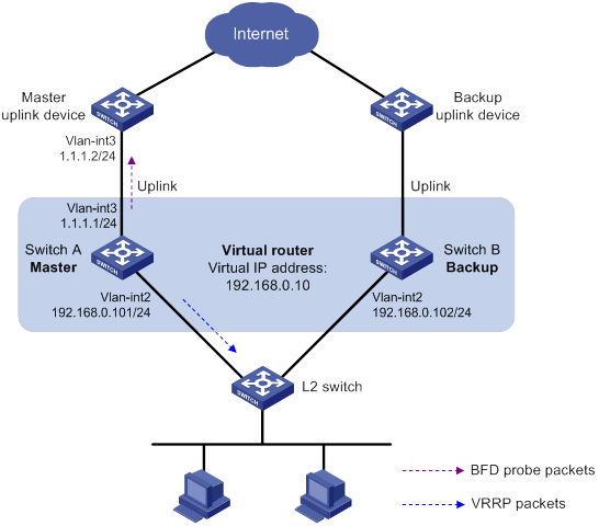
Example: Configuring BFD for the VRRP master to monitor the uplinks
Network configuration
As shown in Figure 4:
· Switch A and Switch B belong to VRRP group 1. The virtual IP address of VRRP group 1 is 192.168.0.10.
· The default gateway of the hosts in the LAN is 192.168.0.10.
Configure VRRP-Track-BFD collaboration to monitor the uplink on the master and meet the following requirements:
· When Switch A operates correctly, the hosts in the LAN access the Internet through Switch A.
· When Switch A detects that the uplink is down through BFD, Switch B can preempt as the master. The hosts in the LAN can access the Internet through Switch B.
Procedure
1. Create VLANs and assign ports to them. Configure the IP address of each VLAN interface, as shown in Figure 4. (Details not shown.)
2. Configure Switch A:
# Specify 10.10.10.10 as the source address of BFD echo packets.
<SwitchA> system-view
[SwitchA] bfd echo-source-ip 10.10.10.10
# Create track entry 1 for the BFD session to verify the reachability of the uplink device (1.1.1.2 ).
[SwitchA] track 1 bfd echo interface vlan-interface 3 remote ip 1.1.1.2 local ip 1.1.1.1
# Create VRRP group 1, and specify 192.168.0.10 as the virtual IP address of the group.
[SwitchA] interface vlan-interface 2
[SwitchA-Vlan-interface2] vrrp vrid 1 virtual-ip 192.168.0.10
# Set the priority of Switch A to 110 in VRRP group 1.
[SwitchA-Vlan-interface2] vrrp vrid 1 priority 110
# Associate VRRP group 1 with track entry 1 and decrease the router priority by 20 when the state of track entry 1 changes to negative.
[SwitchA-Vlan-interface2] vrrp vrid 1 track 1 priority reduced 20
[SwitchA-Vlan-interface2] return
3. On Switch B, create VRRP group 1, and specify 192.168.0.10 as the virtual IP address of the group.
<SwitchB> system-view
[SwitchB] interface vlan-interface 2
[SwitchB-Vlan-interface2] vrrp vrid 1 virtual-ip 192.168.0.10
[SwitchB-Vlan-interface2] return
Verifying the configuration
# Display detailed information about the VRRP group on Switch A.
<SwitchA> display vrrp verbose
IPv4 Virtual Router Information:
Running Mode : Standard
Total number of virtual routers : 1
Interface Vlan-interface2
VRID : 1 Adver Timer : 100
Admin Status : Up State : Master
Config Pri : 110 Running Pri : 110
Preempt Mode : Yes Delay Time : 0
Auth Type : None
Virtual IP : 192.168.0.10
Virtual MAC : 0000-5e00-0101
Master IP : 192.168.0.101
VRRP Track Information:
Track Object : 1 State : Positive Pri Reduced : 20
# Display information about track entry 1 on Switch A.
<SwitchA> display track 1
Track ID: 1
State: Positive
Duration: 0 days 0 hours 0 minutes 32 seconds
Notification delay: Positive 0, Negative 0 (in seconds)
Tracked object:
BFD session mode: Echo
Outgoing interface: Vlan-interface2
VPN instance name: --
Remote IP: 1.1.1.2
Local IP: 1.1.1.1
# Display detailed information about the VRRP group on Switch B.
<SwitchB> display vrrp verbose
IPv4 Virtual Router Information:
Running Mode : Standard
Total number of virtual routers : 1
Interface Vlan-interface2
VRID : 1 Adver Timer : 100
Admin Status : Up State : Backup
Config Pri : 100 Running Pri : 100
Preempt Mode : Yes Delay Time : 0
Become Master : 2200ms left
Auth Type : None
Virtual IP : 192.168.0.10
Master IP : 192.168.0.101
The output shows that when the status of track entry 1 becomes Positive, Switch A is the master and Switch B is the backup.
# Display information about track entry 1 when the uplink of Switch A goes down.
<SwitchA> display track 1
Track ID: 1
State: Negative
Duration: 0 days 0 hours 0 minutes 32 seconds
Notification delay: Positive 0, Negative 0 (in seconds)
Tracked object:
BFD session mode: Echo
Outgoing interface: Vlan-interface2
VPN instance name: --
Remote IP: 1.1.1.2
Local IP: 1.1.1.1
# Display detailed information about VRRP group 1 on Switch A.
<SwitchA> display vrrp verbose
IPv4 Virtual Router Information:
Running Mode : Standard
Total number of virtual routers : 1
Interface Vlan-interface2
VRID : 1 Adver Timer : 100
Admin Status : Up State : Backup
Config Pri : 110 Running Pri : 90
Preempt Mode : Yes Delay Time : 0
Become Master : 2200ms left
Auth Type : None
Virtual IP : 192.168.0.10
Master IP : 192.168.0.102
VRRP Track Information:
Track Object : 1 State : Negative Pri Reduced : 20
# Display detailed information about VRRP group 1 on Switch B.
<SwitchB> display vrrp verbose
IPv4 Virtual Router Information:
Running Mode : Standard
Total number of virtual routers : 1
Interface Vlan-interface2
VRID : 1 Adver Timer : 100
Admin Status : Up State : Master
Config Pri : 100 Running Pri : 100
Preempt Mode : Yes Delay Time : 0
Auth Type : None
Virtual IP : 192.168.0.10
Virtual MAC : 0000-5e00-0101
Master IP : 192.168.0.102
The output shows that when Switch A detects that the uplink fails through BFD, it decreases its priority by 20. Switch B then preempts as the master.
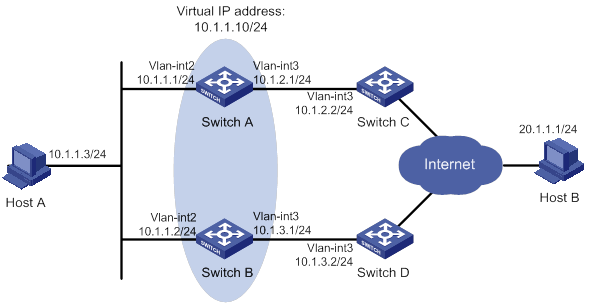
Example: Configuring static routing-Track-NQA collaboration
Network configuration
As shown in Figure 5:
· Switch A is the default gateway of the hosts in network 20.1.1.0/24.
· Switch D is the default gateway of the hosts in network 30.1.1.0/24.
· Hosts in the two networks communicate with each other through static routes.
To ensure network availability, configure route backup and static routing-Track-NQA collaboration on Switch A and Switch D as follows:
· On Switch A, assign a higher priority to the static route to 30.1.1.0/24 with next hop Switch B. This route is the master route. The static route to 30.1.1.0/24 with next hop Switch C acts as the backup route. When the master route is unavailable, the backup route takes effect. Switch A forwards packets to 30.1.1.0/24 through Switch C.
· On Switch D, assign a higher priority to the static route to 20.1.1.0/24 with next hop Switch B. This route is the master route. The static route to 20.1.1.0/24 with next hop Switch C acts as the backup route. When the master route is unavailable, the backup route takes effect. Switch D forwards packets to 20.1.1.0/24 through Switch C.
Procedure
1. Create VLANs and assign ports to them. Configure the IP address of each VLAN interface, as shown in Figure 5. (Details not shown.)
2. Configure Switch A:
# Configure a static route to 30.1.1.0/24 with next hop 10.1.1.2 and the default priority (60). Associate this static route with track entry 1.
<SwitchA> system-view
[SwitchA] ip route-static 30.1.1.0 24 10.1.1.2 track 1
# Configure a static route to 30.1.1.0/24 with next hop 10.3.1.3 and priority 80.
[SwitchA] ip route-static 30.1.1.0 24 10.3.1.3 preference 80
# Configure a static route to 10.2.1.4 with next hop 10.1.1.2.
[SwitchA] ip route-static 10.2.1.4 24 10.1.1.2
# Create an NQA operation with administrator name admin and operation tag test.
[SwitchA] nqa entry admin test
# Specify the ICMP echo operation type.
[SwitchA-nqa-admin-test] type icmp-echo
# Specify 10.2.1.4 as the destination address of the operation.
[SwitchA-nqa-admin-test-icmp-echo] destination ip 10.2.1.4
# Specify 10.1.1.2 as the next hop of the operation.
[SwitchA-nqa-admin-test-icmp-echo] next-hop ip 10.1.1.2
# Configure the ICMP echo operation to repeat every 100 milliseconds.
[SwitchA-nqa-admin-test-icmp-echo] frequency 100
# Configure reaction entry 1, specifying that five consecutive probe failures trigger the Track module.
[SwitchA-nqa-admin-test-icmp-echo] reaction 1 checked-element probe-fail threshold-type consecutive 5 action-type trigger-only
[SwitchA-nqa-admin-test-icmp-echo] quit
# Start the NQA operation.
[SwitchA] nqa schedule admin test start-time now lifetime forever
# Configure track entry 1, and associate it with reaction entry 1 of the NQA operation.
[SwitchA] track 1 nqa entry admin test reaction 1
3. Configure Switch B:
# Configure a static route to 30.1.1.0/24 with next hop 10.2.1.4.
<SwitchB> system-view
[SwitchB] ip route-static 30.1.1.0 24 10.2.1.4
# Configure a static route to 20.1.1.0/24 with next hop 10.1.1.1.
[SwitchB] ip route-static 20.1.1.0 24 10.1.1.1
4. Configure Switch C:
# Configure a static route to 30.1.1.0/24 with next hop 10.4.1.4.
<SwitchC> system-view
[SwitchC] ip route-static 30.1.1.0 24 10.4.1.4
# Configure a static route to 20.1.1.0/24 with next hop 10.3.1.1.
[SwitchC] ip route-static 20.1.1.0 24 10.3.1.1
5. Configure Switch D:
# Configure a static route to 20.1.1.0/24 with next hop 10.2.1.2 and the default priority (60). Associate this static route with track entry 1.
<SwitchD> system-view
[SwitchD] ip route-static 20.1.1.0 24 10.2.1.2 track 1
# Configure a static route to 20.1.1.0/24 with next hop 10.4.1.3 and priority 80.
[SwitchD] ip route-static 20.1.1.0 24 10.4.1.3 preference 80
# Configure a static route to 10.1.1.1 with next hop 10.2.1.2.
[SwitchD] ip route-static 10.1.1.1 24 10.2.1.2
# Create an NQA operation with administrator name admin and operation tag test.
[SwitchD] nqa entry admin test
# Specify the ICMP echo operation type.
[SwitchD-nqa-admin-test] type icmp-echo
# Specify 10.1.1.1 as the destination address of the operation.
[SwitchD-nqa-admin-test-icmp-echo] destination ip 10.1.1.1
# Specify 10.2.1.2 as the next hop of the operation.
[SwitchD-nqa-admin-test-icmp-echo] next-hop ip 10.2.1.2
# Configure the ICMP echo operation to repeat every 100 milliseconds.
[SwitchD-nqa-admin-test-icmp-echo] frequency 100
# Configure reaction entry 1, specifying that five consecutive probe failures trigger the Track module.
[SwitchD-nqa-admin-test-icmp-echo] reaction 1 checked-element probe-fail threshold-type consecutive 5 action-type trigger-only
[SwitchD-nqa-admin-test-icmp-echo] quit
# Start the NQA operation.
[SwitchD] nqa schedule admin test start-time now lifetime forever
# Configure track entry 1, and associate it with reaction entry 1 of the NQA operation.
[SwitchD] track 1 nqa entry admin test reaction 1
Verifying the configuration
# Display information about the track entry on Switch A.
[SwitchA] display track all
Track ID: 1
State: Positive
Duration: 0 days 0 hours 0 minutes 32 seconds
Notification delay: Positive 0, Negative 0 (in seconds)
Tracked object:
NQA entry: admin test
Reaction: 1
Remote IP/URL:--
Local IP:--
Interface:--
The output shows that the status of the track entry is Positive, indicating that the NQA operation has succeeded and the master route is available.
# Display the routing table of Switch A.
[SwitchA] display ip routing-table
Destinations : 10 Routes : 10
Destination/Mask Proto Pre Cost NextHop Interface
10.1.1.0/24 Direct 0 0 10.1.1.1 Vlan2
10.1.1.1/32 Direct 0 0 127.0.0.1 InLoop0
10.2.1.0/24 Static 60 0 10.1.1.2 Vlan2
10.3.1.0/24 Direct 0 0 10.3.1.1 Vlan3
10.3.1.1/32 Direct 0 0 127.0.0.1 InLoop0
20.1.1.0/24 Direct 0 0 20.1.1.1 Vlan6
20.1.1.1/32 Direct 0 0 127.0.0.1 InLoop0
30.1.1.0/24 Static 60 0 10.1.1.2 Vlan2
127.0.0.0/8 Direct 0 0 127.0.0.1 InLoop0
127.0.0.1/32 Direct 0 0 127.0.0.1 InLoop0
The output shows that Switch A forwards packets to 30.1.1.0/24 through Switch B.
# Remove the IP address of interface VLAN-interface 2 on Switch B.
<SwitchB> system-view
[SwitchB] interface vlan-interface 2
[SwitchB-Vlan-interface2] undo ip address
# Display information about the track entry on Switch A.
[SwitchA] display track all
Track ID: 1
State: Negative
Duration: 0 days 0 hours 0 minutes 32 seconds
Notification delay: Positive 0, Negative 0 (in seconds)
Tracked object:
NQA entry: admin test
Reaction: 1
Remote IP/URL:--
Local IP:--
Interface:--
The output shows that the status of the track entry is Negative, indicating that the NQA operation has failed and the master route is unavailable.
# Display the routing table of Switch A.
[SwitchA] display ip routing-table
Destinations : 10 Routes : 10
Destination/Mask Proto Pre Cost NextHop Interface
10.1.1.0/24 Direct 0 0 10.1.1.1 Vlan2
10.1.1.1/32 Direct 0 0 127.0.0.1 InLoop0
10.2.1.0/24 Static 60 0 10.1.1.2 Vlan2
10.3.1.0/24 Direct 0 0 10.3.1.1 Vlan3
10.3.1.1/32 Direct 0 0 127.0.0.1 InLoop0
20.1.1.0/24 Direct 0 0 20.1.1.1 Vlan6
20.1.1.1/32 Direct 0 0 127.0.0.1 InLoop0
30.1.1.0/24 Static 80 0 10.3.1.3 Vlan3
127.0.0.0/8 Direct 0 0 127.0.0.1 InLoop0
127.0.0.1/32 Direct 0 0 127.0.0.1 InLoop0
The output shows that Switch A forwards packets to 30.1.1.0/24 through Switch C. The backup static route has taken effect.
# Verify that hosts in 20.1.1.0/24 can communicate with the hosts in 30.1.1.0/24 when the master route fails.
[SwitchA] ping -a 20.1.1.1 30.1.1.1
Ping 30.1.1.1: 56 data bytes, press CTRL_C to break
Reply from 30.1.1.1: bytes=56 Sequence=1 ttl=254 time=2 ms
Reply from 30.1.1.1: bytes=56 Sequence=2 ttl=254 time=1 ms
Reply from 30.1.1.1: bytes=56 Sequence=3 ttl=254 time=1 ms
Reply from 30.1.1.1: bytes=56 Sequence=4 ttl=254 time=2 ms
Reply from 30.1.1.1: bytes=56 Sequence=5 ttl=254 time=1 ms
--- Ping statistics for 30.1.1.1 ---
5 packet(s) transmitted, 5 packet(s) received, 0.00% packet loss
round-trip min/avg/max/std-dev = 1/1/2/1 ms
# Verify that the hosts in 30.1.1.0/24 can communicate with the hosts in 20.1.1.0/24 when the master route fails.
[SwitchB] ping -a 30.1.1.1 20.1.1.1
Ping 20.1.1.1: 56 data bytes, press CTRL_C to break
Reply from 20.1.1.1: bytes=56 Sequence=1 ttl=254 time=2 ms
Reply from 20.1.1.1: bytes=56 Sequence=2 ttl=254 time=1 ms
Reply from 20.1.1.1: bytes=56 Sequence=3 ttl=254 time=1 ms
Reply from 20.1.1.1: bytes=56 Sequence=4 ttl=254 time=1 ms
Reply from 20.1.1.1: bytes=56 Sequence=5 ttl=254 time=1 ms
--- Ping statistics for 20.1.1.1 ---
5 packet(s) transmitted, 5 packet(s) received, 0.00% packet loss
round-trip min/avg/max/std-dev = 1/1/2/1 ms
Example: Configuring static routing-Track-BFD collaboration
Network configuration
As shown in Figure 6:
· Switch A is the default gateway of the hosts in network 20.1.1.0/24.
· Switch B is the default gateway of the hosts in network 30.1.1.0/24.
· Hosts in the two networks communicate with each other through static routes.
To ensure network availability, configure route backup and static routing-Track-BFD collaboration on Switch A and Switch B as follows:
· On Switch A, assign a higher priority to the static route to 30.1.1.0/24 with next hop Switch B. This route is the master route. The static route to 30.1.1.0/24 with next hop Switch C acts as the backup route. When the master route is unavailable, BFD can quickly detect the route failure to make the backup route take effect.
· On Switch B, assign a higher priority to the static route to 20.1.1.0/24 with next hop Switch A. This route is the master route. The static route to 20.1.1.0/24 with next hop Switch C acts as the backup route. When the master route is unavailable, BFD can quickly detect the route failure to make the backup route take effect.
Procedure
1. Create VLANs and assign ports to them. Configure the IP address of each VLAN interface, as shown in Figure 6. (Details not shown.)
2. Configure Switch A:
# Configure a static route to 30.1.1.0/24 with next hop 10.2.1.2 and the default priority (60). Associate this static route with track entry 1.
<SwitchA> system-view
[SwitchA] ip route-static 30.1.1.0 24 10.2.1.2 track 1
# Configure a static route to 30.1.1.0/24 with next hop 10.3.1.3 and priority 80.
[SwitchA] ip route-static 30.1.1.0 24 10.3.1.3 preference 80
# Specify 10.10.10.10 as the source address of BFD echo packets.
[SwitchA] bfd echo-source-ip 10.10.10.10
# Configure track entry 1, and associate it with the BFD session to verify the connectivity between Switch A and Switch B.
[SwitchA] track 1 bfd echo interface vlan-interface 2 remote ip 10.2.1.2 local ip 10.2.1.1
3. Configure Switch B:
# Configure a static route to 20.1.1.0/24 with next hop 10.2.1.1 and the default priority (60). Associate this static route with track entry 1.
<SwitchB> system-view
[SwitchB] ip route-static 20.1.1.0 24 10.2.1.1 track 1
# Configure a static route to 20.1.1.0/24 with next hop 10.4.1.3 and priority 80.
[SwitchB] ip route-static 20.1.1.0 24 10.4.1.3 preference 80
# Specify 1.1.1.1 as the source address of BFD echo packets.
[SwitchB] bfd echo-source-ip 1.1.1.1
# Configure track entry 1, and associate it with the BFD session to verify the connectivity between Switch B and Switch A.
[SwitchB] track 1 bfd echo interface vlan-interface 2 remote ip 10.2.1.1 local ip 10.2.1.2
4. Configure Switch C:
# Configure a static route to 30.1.1.0/24 with next hop 10.4.1.2.
<SwitchC> system-view
[SwitchC] ip route-static 30.1.1.0 24 10.4.1.2
# Configure a static route to 20.1.1.0/24 with next hop 10.3.1.1.
[SwitchB] ip route-static 20.1.1.0 24 10.3.1.1
Verifying the configuration
# Display information about the track entry on Switch A.
[SwitchA] display track all
Track ID: 1
State: Positive
Duration: 0 days 0 hours 0 minutes 32 seconds
Notification delay: Positive 0, Negative 0 (in seconds)
Tracked object:
BFD session mode: Echo
Outgoing interface: Vlan-interface2
Remote IP: 10.2.1.2
Local IP: 10.2.1.1
The output shows that the status of the track entry is Positive, indicating that next hop 10.2.1.2 is reachable.
# Display the routing table of Switch A.
[SwitchA] display ip routing-table
Destinations : 9 Routes : 9
Destination/Mask Proto Pre Cost NextHop Interface
10.2.1.0/24 Direct 0 0 10.2.1.1 Vlan2
10.2.1.1/32 Direct 0 0 127.0.0.1 InLoop0
10.3.1.0/24 Direct 0 0 10.3.1.1 Vlan3
10.3.1.1/32 Direct 0 0 127.0.0.1 InLoop0
20.1.1.0/24 Direct 0 0 20.1.1.1 Vlan5
20.1.1.1/32 Direct 0 0 127.0.0.1 InLoop0
30.1.1.0/24 Static 60 0 10.2.1.2 Vlan2
127.0.0.0/8 Direct 0 0 127.0.0.1 InLoop0
127.0.0.1/32 Direct 0 0 127.0.0.1 InLoop0
The output shows that Switch A forwards packets to 30.1.1.0/24 through Switch B. The master static route has taken effect.
# Remove the IP address of VLAN-interface 2 on Switch B.
<SwitchB> system-view
[SwitchB] interface vlan-interface 2
[SwitchB-Vlan-interface2] undo ip address
# Display information about the track entry on Switch A.
[SwitchA] display track all
Track ID: 1
State: Negative
Duration: 0 days 0 hours 0 minutes 32 seconds
Notification delay: Positive 0, Negative 0 (in seconds)
Tracked object:
BFD session mode: Echo
Outgoing interface: Vlan-interface2
VPN instance name: --
Remote IP: 10.2.1.2
Local IP: 10.2.1.1
The output shows that the status of the track entry is Negative, indicating that next hop 10.2.1.2 is unreachable.
# Display the routing table of Switch A.
[SwitchA] display ip routing-table
Destinations : 9 Routes : 9
Destination/Mask Proto Pre Cost NextHop Interface
10.2.1.0/24 Direct 0 0 10.2.1.1 Vlan2
10.2.1.1/32 Direct 0 0 127.0.0.1 InLoop0
10.3.1.0/24 Direct 0 0 10.3.1.1 Vlan3
10.3.1.1/32 Direct 0 0 127.0.0.1 InLoop0
20.1.1.0/24 Direct 0 0 20.1.1.1 Vlan5
20.1.1.1/32 Direct 0 0 127.0.0.1 InLoop0
30.1.1.0/24 Static 80 0 10.3.1.3 Vlan3
127.0.0.0/8 Direct 0 0 127.0.0.1 InLoop0
127.0.0.1/32 Direct 0 0 127.0.0.1 InLoop0
The output shows that Switch A forwards packets to 30.1.1.0/24 through Switch C. The backup static route has taken effect.
# Verify that the hosts in 20.1.1.0/24 can communicate with the hosts in 30.1.1.0/24 when the master route fails.
[SwitchA] ping -a 20.1.1.1 30.1.1.1
Ping 30.1.1.1: 56 data bytes, press CTRL_C to break
Reply from 30.1.1.1: bytes=56 Sequence=1 ttl=254 time=2 ms
Reply from 30.1.1.1: bytes=56 Sequence=2 ttl=254 time=1 ms
Reply from 30.1.1.1: bytes=56 Sequence=3 ttl=254 time=1 ms
Reply from 30.1.1.1: bytes=56 Sequence=4 ttl=254 time=2 ms
Reply from 30.1.1.1: bytes=56 Sequence=5 ttl=254 time=1 ms
--- Ping statistics for 30.1.1.1 ---
5 packet(s) transmitted, 5 packet(s) received, 0.00% packet loss
round-trip min/avg/max/std-dev = 1/1/2/1 ms
# Verify that the hosts in 30.1.1.0/24 can still communicate with the hosts in 20.1.1.0/24 when the master route fails.
[SwitchB] ping -a 30.1.1.1 20.1.1.1
Ping 20.1.1.1: 56 data bytes, press CTRL_C to break
Reply from 20.1.1.1: bytes=56 Sequence=1 ttl=254 time=2 ms
Reply from 20.1.1.1: bytes=56 Sequence=2 ttl=254 time=1 ms
Reply from 20.1.1.1: bytes=56 Sequence=3 ttl=254 time=1 ms
Reply from 20.1.1.1: bytes=56 Sequence=4 ttl=254 time=1 ms
Reply from 20.1.1.1: bytes=56 Sequence=5 ttl=254 time=1 ms
--- Ping statistics for 20.1.1.1 ---
5 packet(s) transmitted, 5 packet(s) received, 0.00% packet loss
round-trip min/avg/max/std-dev = 1/1/2/1 ms
Example: Configuring VRRP-Track-interface management collaboration
Network configuration
As shown in Figure 7:
· Host A requires access to Host B. The default gateway of Host A is 10.1.1.10/24.
· Switch A and Switch B belong to VRRP group 1. The virtual IP address of VRRP group 1 is 10.1.1.10.
Configure VRRP-Track-interface management collaboration to monitor the uplink interface on the master and meet the following requirements:
· When Switch A operates correctly, Switch A forwards packets from Host A to Host B.
· When VRRP detects a fault on the uplink interface of Switch A through the interface management module, Switch B forwards packets from Host A to Host B.
Procedure
1. Create VLANs and assign ports to them. Configure the IP address of each VLAN interface, as shown in Figure 7. (Details not shown.)
2. Configure Switch A:
# Configure track entry 1 and associate it with the link status of the uplink interface VLAN-interface 3.
[SwitchA] track 1 interface vlan-interface 3
# Create VRRP group 1 and configure virtual IP address 10.1.1.10 for the group.
[SwitchA] interface vlan-interface 2
[SwitchA-Vlan-interface2] vrrp vrid 1 virtual-ip 10.1.1.10
# Set the priority of Switch A to 110 in VRRP group 1.
[SwitchA-Vlan-interface2] vrrp vrid 1 priority 110
# Associate VRRP group 1 with track entry 1 and decrease the router priority by 30 when the state of track entry 1 changes to negative.
[SwitchA-Vlan-interface2] vrrp vrid 1 track 1 priority reduced 30
3. On Switch B, create VRRP group 1, and configure virtual IP address 10.1.1.10 for the group.
<SwitchB> system-view
[SwitchB] interface vlan-interface 2
[SwitchB-Vlan-interface2] vrrp vrid 1 virtual-ip 10.1.1.10
Verifying the configuration
# Ping Host B from Host A to verify that Host B is reachable. (Details not shown.)
# Display detailed information about VRRP group 1 on Switch A.
[SwitchA-Vlan-interface2] display vrrp verbose
IPv4 Virtual Router Information:
Running Mode : Standard
Total number of virtual routers : 1
Interface Vlan-interface2
VRID : 1 Adver Timer : 100
Admin Status : Up State : Master
Config Pri : 110 Running Pri : 110
Preempt Mode : Yes Delay Time : 0
Auth Type : None
Virtual IP : 10.1.1.10
Virtual MAC : 0000-5e00-0101
Master IP : 10.1.1.1
VRRP Track Information:
Track Object : 1 State : Positive Pri Reduced : 30
# Display detailed information about VRRP group 1 on Switch B.
[SwitchB-Vlan-interface2] display vrrp verbose
IPv4 Virtual Router Information:
Running Mode : Standard
Total number of virtual routers : 1
Interface Vlan-interface2
VRID : 1 Adver Timer : 100
Admin Status : Up State : Backup
Config Pri : 100 Running Pri : 100
Preempt Mode : Yes Delay Time : 0
Become Master : 2200ms left
Auth Type : None
Virtual IP : 10.1.1.10
Master IP : 10.1.1.1
The output shows that in VRRP group 1, Switch A is the master, and Switch B is a backup. Switch A forwards packets from Host A to Host B.
# Shut down the uplink interface VLAN-interface 3 on Switch A.
[SwitchA-Vlan-interface2] interface vlan-interface 3
[SwitchA-Vlan-interface3] shutdown
# Ping Host B from Host A to verify that Host B is reachable. (Details not shown.)
# Display detailed information about VRRP group 1 on Switch A.
[SwitchA-Vlan-interface3] display vrrp verbose
IPv4 Virtual Router Information:
Running Mode : Standard
Total number of virtual routers : 1
Interface Vlan-interface2
VRID : 1 Adver Timer : 100
Admin Status : Up State : Backup
Config Pri : 110 Running Pri : 80
Preempt Mode : Yes Delay Time : 0
Become Master : 2200ms left
Auth Type : None
Virtual IP : 10.1.1.10
Master IP : 10.1.1.2
VRRP Track Information:
Track Object : 1 State : Negative Pri Reduced : 30
# Display detailed information about VRRP group 1 on Switch B.
[SwitchB-Vlan-interface2] display vrrp verbose
IPv4 Virtual Router Information:
Running Mode : Standard
Total number of virtual routers : 1
Interface Vlan-interface2
VRID : 1 Adver Timer : 100
Admin Status : Up State : Master
Config Pri : 100 Running Pri : 100
Preempt Mode : Yes Delay Time : 0
Auth Type : None
Virtual IP : 10.1.1.10
Virtual MAC : 0000-5e00-0101
Master IP : 10.1.1.2
The output shows that Switch A becomes the backup, and Switch B becomes the master. Switch B forwards packets from Host A to Host B.
Example: Configuring VRRP-Track-route management collaboration
Network configuration
As shown in Figure 8:
· Host A requires access to Host B. The default gateway of Host A is 10.1.1.10/24.
· Switch A and Switch B belong to VRRP group 1. The virtual IP address of VRRP group 1 is 10.1.1.10.
· BGP peer relationships are established between Switch A and Switch C and between Switch B and Switch D. Switch C and Switch D advertise the default route 0.0.0.0/0 to Switch A and Switch B.
Configure VRRP-Track-route management collaboration to meet the following requirements:
· When Switch A operates correctly, Switch A forwards packets from Host A to Host B.
· When VRRP detects the removal of the default route from the routing table of Switch A through route management, Switch B forwards packets from Host A to Host B.
Procedure
1. Configure the IP address of each interface, as shown in Figure 8. (Details not shown.)
2. Establish an IBGP peer relationship between Switch A and Switch C, and configure Switch C to advertise the default route 0.0.0.0/0 to Switch A.
<SwitchA> system-view
[SwitchA] bgp 100
[SwitchA-bgp-default] peer 10.1.2.2 as-number 100
[SwitchA-bgp-default] address-family ipv4
[SwitchA-bgp-default-ipv4] peer 10.1.2.2 enable
<SwitchC> system-view
[SwitchC] bgp 100
[SwitchC-bgp-default] peer 10.1.2.1 as-number 100
[SwitchC-bgp-default] address-family ipv4
[SwitchC-bgp-default-ipv4] peer 10.1.2.1 enable
[SwitchC-bgp-default-ipv4] peer 10.1.2.1 default-route-advertise
[SwitchC-bgp-default-ipv4] quit
3. Configure Switch B and Switch D in the same way Switch A and Switch C are configured. (Details not shown.)
4. Configure Track and VRRP on Switch A:
# Configure track entry 1, and associate it with the default route 0.0.0.0/0.
[SwitchA] track 1 ip route 0.0.0.0 0.0.0.0 reachability
# Create VRRP group 1, and configure virtual IP address 10.1.1.10 for the group.
[SwitchA] interface vlan-interface 2
[SwitchA-Vlan-interface2] vrrp vrid 1 virtual-ip 10.1.1.10
# Set the priority of Switch A to 110 in VRRP group 1.
[SwitchA-Vlan-interface2] vrrp vrid 1 priority 110
# Associate VRRP group 1 with track entry 1 and decrease the Switch priority by 30 when the state of track entry 1 changes to negative.
[SwitchA-Vlan-interface2] vrrp vrid 1 track 1 priority reduced 30
[SwitchA-Vlan-interface2] quit
5. On Switch B, create VRRP group 1, and configure virtual IP address 10.1.1.10 for the group.
<SwitchB> system-view
[SwitchB] interface vlan-interface 2
[SwitchB-Vlan-interface2] vrrp vrid 1 virtual-ip 10.1.1.10
[SwitchB-Vlan-interface2] quit
Verifying the configuration
# Ping Host B from Host A to verify that Host B is reachable. (Details not shown.)
# Display detailed information about VRRP group 1 on Switch A.
[SwitchA] display vrrp verbose
IPv4 Virtual Router Information:
Running Mode : Standard
Total number of virtual routers : 1
Interface Vlan-interface2
VRID : 1 Adver Timer : 100
Admin Status : Up State : Master
Config Pri : 110 Running Pri : 110
Preempt Mode : Yes Delay Time : 0
Auth Type : None
Virtual IP : 10.1.1.10
Virtual MAC : 0000-5e00-0101
Master IP : 10.1.1.1
VRRP Track Information:
Track Object : 1 State : Positive Pri Reduced : 30
# Display detailed information about VRRP group 1 on Switch B.
[SwitchB] display vrrp verbose
IPv4 Virtual Router Information:
Running Mode : Standard
Total number of virtual routers : 1
Interface Vlan-interface2
VRID : 1 Adver Timer : 100
Admin Status : Up State : Backup
Config Pri : 100 Running Pri : 100
Preempt Mode : Yes Delay Time : 0
Become Master : 2200ms left
Auth Type : None
Virtual IP : 10.1.1.10
Master IP : 10.1.1.1
The output shows that in VRRP group 1, Switch A is the master and Switch B is a backup. Switch A forwards packets from Host A to Host B.
# Disable Switch C from exchanging routing information with Switch A so that the default route 0.0.0.0/0 is removed from the routing table of Switch A.
[SwitchC-bgp-default-ipv4] undo peer 10.1.2.1 enable
# Ping Host B from Host A to verify that Host B is reachable. (Details not shown.)
# Display detailed information about VRRP group 1 on Switch A.
[SwitchA] display vrrp verbose
IPv4 Virtual Router Information:
Running Mode : Standard
Total number of virtual routers : 1
Interface Vlan-interface2
VRID : 1 Adver Timer : 100
Admin Status : Up State : Backup
Config Pri : 110 Running Pri : 80
Preempt Mode : Yes Delay Time : 0
Become Master : 2200ms left
Auth Type : None
Virtual IP : 10.1.1.10
Master IP : 10.1.1.2
VRRP Track Information:
Track Object : 1 State : Negative Pri Reduced : 30
# Display detailed information about VRRP group 1 on Switch B.
[SwitchB] display vrrp verbose
IPv4 Virtual Router Information:
Running Mode : Standard
Total number of virtual routers : 1
Interface Vlan-interface2
VRID : 1 Adver Timer : 100
Admin Status : Up State : Master
Config Pri : 100 Running Pri : 100
Preempt Mode : Yes Delay Time : 0
Auth Type : None
Virtual IP : 10.1.1.10
Virtual MAC : 0000-5e00-0101
Master IP : 10.1.1.2
The output shows that Switch A becomes the backup, and Switch B becomes the master. Switch B forwards packets from Host A to Host B.
Example: Configuring static routing-Track-LLDP collaboration
Network requirements
As shown in Figure 9:
· Device A is the default gateway of the hosts in network 20.1.1.0/24.
· Device B is the default gateway of the hosts in network 30.1.1.0/24.
· Hosts in the two networks communicate with each other through static routes.
To ensure network availability, configure route backup and static routing-Track-LLDP collaboration on Device A and Device B as follows:
· On Device A, assign a higher priority to the static route to 30.1.1.0/24 with next hop Device B. This route is the master route. The static route to 30.1.1.0/24 with next hop Device C acts as the backup route. When the master route is unavailable, the backup route takes effect. Device A forwards packets destined for 30.1.1.0/24 to Device C.
· On Device B, assign a higher priority to the static route to 20.1.1.0/24 with next hop Device A. This route is the master route. The static route to 20.1.1.0/24 with next hop Device C acts as the backup route. When the master route is unavailable, the backup route takes effect. Device B forwards packets destined for 20.1.1.0/24 to Device C.
Procedure
1. Configure the IP address of each interface, as shown in Figure 9. (Details not shown.)
2. Configure Device A:
# Configure a static route to 30.1.1.0/24 with next hop 10.1.1.2 and the default priority (60). Associate this static route with track entry 1.
<DeviceA> system-view
[DeviceA] ip route-static 30.1.1.0 24 10.2.1.2 track 1
# Configure a static route to 30.1.1.0/24 with next hop 10.3.1.3 and priority 80.
[DeviceA] ip route-static 30.1.1.0 24 10.3.1.3 preference 80
# Enable LLDP globally.
[DeviceA] lldp global enable
# Enable LLDP on GigabitEthernet 1/0/1. (This step is optional because LLDP is enabled on the port by default.)
[DeviceA] interface gigabitethernet 1/0/1
[DeviceA-GigabitEthernet1/0/1] lldp enable
# Configure track entry 1 and associate it with the availability of the neighbor for LLDP interface Gigabitethernet 1/0/1.
[DeviceA] track 1 lldp neighbor interface gigabitethernet 1/0/1
3. Configure Device B:
# Configure a static route to 20.1.1.0/24 with next hop 10.2.1.1 and the default priority (60). Associate this static route with track entry 1.
<DeviceB> system-view
[DeviceB] ip route-static 20.1.1.0 24 10.2.1.1 track 1
# Configure a static route to 20.1.1.0/24 with next hop 10.4.1.3 and priority 80.
[DeviceB] ip route-static 20.1.1.0 24 10.4.1.3 preference 80
# Enable LLDP globally.
[DeviceB] lldp global enable
# Enable LLDP on GigabitEthernet 1/0/1. (This step is optional because LLDP is enabled on the port by default.)
[DeviceB] interface gigabitethernet 1/0/1
[DeviceB-GigabitEthernet1/0/1] lldp enable
# Configure track entry 1 and associate it with the availability of the neighbor for LLDP interface GigabitEthernet 1/0/1.
[DeviceB] track 1 lldp neighbor interface gigabitethernet 1/0/1
4. Configure Device C:
# Configure a static route to 30.1.1.0/24 with next hop 10.4.1.2.
<DeviceC> system-view
[DeviceC] ip route-static 30.1.1.0 24 10.4.1.2
# Configure a static route to 20.1.1.0/24 with next hop 10.3.1.1.
[DeviceC] ip route-static 20.1.1.0 24 10.3.1.1
Verifying the configuration
# Display track entry information on Device A.
[DeviceA] display track all
Track ID: 1
State: Positive
Duration: 0 days 0 hours 0 minutes 32 seconds
Notification delay: Positive 0, Negative 0 (in seconds)
Tracked object:
LLDP interface: GigabitEthernet1/0/1
The output shows that the status of track entry 1 is Positive, indicating that the neighbor of LLDP interface GigabitEthernet 1/0/1 is available. The master route takes effect.
# Display the routing table of Device A.
[DeviceA] display ip routing-table
Destinations : 9 Routes : 9
Destination/Mask Proto Pre Cost NextHop Interface
10.2.1.0/24 Direct 0 0 10.2.1.1 GE1/0/1
10.2.1.1/32 Direct 0 0 127.0.0.1 InLoop0
10.3.1.0/24 Direct 0 0 10.3.1.1 GE1/0/2
10.3.1.1/32 Direct 0 0 127.0.0.1 InLoop0
20.1.1.0/24 Direct 0 0 20.1.1.1 GE1/0/3
20.1.1.1/32 Direct 0 0 127.0.0.1 InLoop0
30.1.1.0/24 Static 60 0 10.2.1.2 GE1/0/1
127.0.0.0/8 Direct 0 0 127.0.0.1 InLoop0
127.0.0.1/32 Direct 0 0 127.0.0.1 InLoop0
The output shows that Device A forwards packets to 30.1.1.0/24 through Device B.
# On Device B, disable LLDP on GigabitEthernet 1/0/1.
<DeviceB> system-view
[DeviceB] interface gigabitethernet 1/0/1
[DeviceB-GigabitEthernet1/0/1] undo lldp enable
# Display track entry information on Device A.
[DeviceA] display track all
Track ID: 1
State: Negative
Duration: 0 days 0 hours 0 minutes 32 seconds
Notification delay: Positive 0, Negative 0 (in seconds)
Tracked object:
LLDP interface: GigabitEthernet1/0/1
The output shows that the status of track entry 1 is Negative, indicating that the neighbor of LLDP interface GigabitEthernet 1/0/1 is unavailable. The master route fails.
# Display the routing table of Device A.
[DeviceA] display ip routing-table
Destinations : 9 Routes : 9
Destination/Mask Proto Pre Cost NextHop Interface
10.2.1.0/24 Direct 0 0 10.2.1.1 GE1/0/1
10.2.1.1/32 Direct 0 0 127.0.0.1 InLoop0
10.3.1.0/24 Direct 0 0 10.3.1.1 GE1/0/2
10.3.1.1/32 Direct 0 0 127.0.0.1 InLoop0
20.1.1.0/24 Direct 0 0 20.1.1.1 GE1/0/3
20.1.1.1/32 Direct 0 0 127.0.0.1 InLoop0
30.1.1.0/24 Static 80 0 10.3.1.3 GE1/0/2
127.0.0.0/8 Direct 0 0 127.0.0.1 InLoop0
127.0.0.1/32 Direct 0 0 127.0.0.1 InLoop0
The output shows that Device A forwards packets destined for 30.1.1.0/24 to Device C. The backup static route has taken effect.
# Verify that hosts in 20.1.1.0/24 can communicate with the hosts in 30.1.1.0/24 when the master route fails.
[DeviceA] ping -a 20.1.1.1 30.1.1.1
Ping 30.1.1.1: 56 data bytes, press CTRL_C to break
Reply from 30.1.1.1: bytes=56 Sequence=1 ttl=254 time=2 ms
Reply from 30.1.1.1: bytes=56 Sequence=2 ttl=254 time=1 ms
Reply from 30.1.1.1: bytes=56 Sequence=3 ttl=254 time=1 ms
Reply from 30.1.1.1: bytes=56 Sequence=4 ttl=254 time=2 ms
Reply from 30.1.1.1: bytes=56 Sequence=5 ttl=254 time=1 ms
--- Ping statistics for 30.1.1.1 ---
5 packet(s) transmitted, 5 packet(s) received, 0.00% packet loss
round-trip min/avg/max/std-dev = 1/1/2/1 ms
# Verify that the hosts in 30.1.1.0/24 can communicate with the hosts in 20.1.1.0/24 when the master route fails.
[DeviceB] ping -a 30.1.1.1 20.1.1.1
Ping 20.1.1.1: 56 data bytes, press CTRL_C to break
Reply from 20.1.1.1: bytes=56 Sequence=1 ttl=254 time=2 ms
Reply from 20.1.1.1: bytes=56 Sequence=2 ttl=254 time=1 ms
Reply from 20.1.1.1: bytes=56 Sequence=3 ttl=254 time=1 ms
Reply from 20.1.1.1: bytes=56 Sequence=4 ttl=254 time=1 ms
Reply from 20.1.1.1: bytes=56 Sequence=5 ttl=254 time=1 ms
--- Ping statistics for 20.1.1.1 ---
5 packet(s) transmitted, 5 packet(s) received, 0.00% packet loss
round-trip min/avg/max/std-dev = 1/1/2/1 ms
Example: Configuring Smart Link-Track-CFD collaboration
For information about the Smart Link-Track-CFD collaboration configuration example, see "Configuring Smart Link."